JP3801431B2 - Bullet ball machine - Google Patents
Bullet ball machine Download PDFInfo
- Publication number
- JP3801431B2 JP3801431B2 JP2000280233A JP2000280233A JP3801431B2 JP 3801431 B2 JP3801431 B2 JP 3801431B2 JP 2000280233 A JP2000280233 A JP 2000280233A JP 2000280233 A JP2000280233 A JP 2000280233A JP 3801431 B2 JP3801431 B2 JP 3801431B2
- Authority
- JP
- Japan
- Prior art keywords
- front frame
- frame
- piece
- ride
- riding
- Prior art date
- Legal status (The legal status is an assumption and is not a legal conclusion. Google has not performed a legal analysis and makes no representation as to the accuracy of the status listed.)
- Expired - Fee Related
Links
Images


Description
【0001】
【発明の属する技術分野】
本発明は、矩形状の外枠の前面側に、遊技盤等が設置された前枠が、縦軸廻りに揺動開閉可能に取り付けられているパチンコ機などの弾球遊技機に関するものである。
【0002】
【従来の技術】
パチンコ機やアレンジボール機などの弾球遊技機では、矩形状の外枠の前面側に、縦軸廻りに揺動開閉可能な状態で前枠が取り付けられ、更に外枠の前面側下部に、前枠を閉じたときにその前枠の下方に隣接するように下枠材が固定されているものが一般的である。
【0003】
前枠には、その裏面側に、各種入賞手段や表示手段等が取り付けられた遊技盤、その遊技盤を前枠に対して着脱自在に固定する裏機構板の他、各種制御基板、スイッチ類などが取り付けられており、更に前面側には、遊技盤の前側を覆うガラス扉、遊技球を貯留する上皿が装着された前面板、余剰球を貯留する下皿、遊技球を遊技盤に向けて発射する発射装置等が取り付けられている。
【0004】
以上のような構成を有する弾球遊技機では、前枠を閉じることによって、前枠の下面と外枠の上面とが互いに対向するに至り、前枠と下枠材とによって外枠の前面側が完全に塞がれた状態となる。
【0005】
【発明が解決しようとする課題】
ところで、上述したように、前枠には様々な部品が数多く取り付けられているため、その重量は極めて大きい。従って、前枠を開閉する際には、前枠を開閉自在に支持しているヒンジ部に過大な荷重が作用することとなる。その結果、日常的な前枠の開閉を長期間にわたって繰り返すうちに、ヒンジ部の取り付けガタ等が次第に大きくなり、前枠の開閉端側がヒンジ端側よりも相対的に垂れ下がった状態となる場合が多い。このような状態では、下枠材の上面と前枠の下面とが干渉し、前枠のスムーズな開閉が行えないばかりでなく、開閉時に発生する衝撃によって、例えば前枠に取り付けられている各部品に悪影響を与える虞もあった。
【0006】
本発明は上記事情に鑑みてなされたものであり、その目的とするところは、前枠の開閉を常にスムーズに行うことが可能な弾球遊技機を提供することである。
【0007】
【課題を解決するための手段】
上記目的を達成するために、本発明は、矩形状の外枠1 と、該外枠1 に縦軸廻りに揺動開閉可能に取り付けられる前枠3 と、上記外枠1 の下部に取り付けられ、その上面2aが上記前枠3 を閉じた状態で上記前枠3 の下面3aと対向する下枠材2 と、上記前枠3 の下部に取り付けられ、上記前枠3 に取り付けられた遊技盤6 に向けて遊技球を発射する発射装置13,13',13"とを備えた弾球遊技機において、上記前枠3 を閉じる際に該前枠3 の下面3aを上記下枠材2 の上面2aに乗り上げさせる乗り上げ手段60,61 を備え、この乗り上げ手段60,61 は、上記前枠3 の裏面側に沿って装着される支持片部40と、この支持片部40の下縁部から上記前枠3 の背面側に向けて突出する断面くの字状に形成された乗り上げ片部41と、この乗り上げ片部41から上記前枠3 の下面3aに沿って前面側に向けて延設された下片部42と、該下片部 42 側の一部分が上記乗り上げ片部 41 と上記下片部 42 との境界線に沿って上記前枠 3 の裏面側に沿うように上向きに曲げ起こされて形成された位置決め片部 44 とを備えている。
【0008】
【発明の実施の形態】
以下、図面を参照しつつ、本発明に係る弾球遊技機をパチンコ機として具現化した実施の形態について説明する。図1〜図8は本発明の第1の実施形態を例示し、図1及び図2において、1は矩形状の外枠で、その下端部分の前側には下枠材2が固定されている。更に、外枠1の前側で下枠材2の上方に隣接する位置には、前枠3が、左右方向の一端側、例えば向かって左側の端部に設けられた上下一対のヒンジ部4,4によって、縦軸廻りに揺動開閉自在に取り付けられている。
【0009】
前枠3の前側には窓孔5が取り付けられ、この窓枠5に対応して遊技盤6が裏側から着脱自在に装着され、更にこの遊技盤6の前面側にガラス扉7と前面板8とが開閉自在に装着されている。遊技盤6には、ガイドレール9がほぼ環状に装着されると共に、そのガイドレール9の内側の遊技領域10には、図示しない液晶表示手段、可変式入賞手段、大入賞手段、普通入賞手段、通過ゲート等の各種遊技部品が配置されている。また、前面板8には、発射用の遊技球を貯留する上皿11が装着されており、前枠3の下部には、余剰球を貯留する下皿12と発射装置13とが各々設けられている。
【0010】
また、前枠3の裏側には、遊技盤6を裏側から押さえて固定する裏機構板14が開閉自在に装着されている。この裏機構板14の略中央部分には開口部14aが形成され、その上側には賞球タンク15とこれに接続されたタンクレール16とが、左右方向の片側にはタンクレール16に接続された払出し装置17が、下側には払出し装置17に接続された払出し球誘導路18がそれぞれ設けられている。賞球タンク15からタンクレール16を経由して払出し装置17から払い出された遊技球は、払出し球誘導路18を経由して上皿11に排出される。
【0011】
裏機構板14の開口部14aには、遊技盤6の裏側を覆う裏カバー19が嵌合されている。この裏カバー19には、基板ケース20,21,22が着脱自在に装着されている。基板ケース20内には、遊技盤6の遊技制御を主として司る主制御基板が,基板ケース21内には、遊技盤6等に設けられた多数のランプの点灯制御を行うランプ制御基板が、基板ケース22内には、スピーカから出力する各種効果音等のためのサウンド制御を行うサウンド制御基板がそれぞれ収納されている。また、基板ケース20の前側の裏カバー19内には、図柄制御基板が収納されている。この図柄制御基板は、液晶表示手段に種々の動画や背景画を表示させる表示制御を実行したり、或いは液晶表示手段に設けられた複数の図柄表示部の図柄の変動を制御し、指示された停止図柄で変動を停止させる等の制御を行う。更に、基板ケース21,22の下方の裏機構板14上には、各基板等に電源の供給等を行う電源基板と、払出し装置17による遊技球の払出しを制御する払出し制御基板とが収納された基板ケース23が着脱自在に装着されている。
【0012】
また、発射装置13は、前枠3の向かって右側の下端部近傍に取り付けられており、図3及び図4に示すように、発射レール24(図4参照)上に1個ずつ供給される遊技球を打撃する揺動自在の打撃槌31と、打撃槌31に打撃力を与える発射バネ32と、カム33を介して打撃槌31を間欠的に駆動する駆動モータ34(駆動手段)と、駆動モータ34による打撃槌31の駆動のオン/オフや、発射バネ32のバネ力の調整を行う発射ハンドル35(操作手段)と、発射ハンドル35が取り付けられる取り付けボス部36と、当該発射装置13の制御を司る発射制御基板37が格納された基板ケース38と、打撃槌31、駆動モータ34、発射ハンドル35等を前枠3に固定する取付板39とを備えている。発射バネ32は、例えば一端側が打撃槌31の回転軸に、他端側がワイヤ32aを介して取り付けボス部36内で発射ハンドル35にそれぞれ接続されている。
【0013】
遊技者が発射ハンドル35に触れると、発射ハンドル35に組み込まれているタッチセンサによってこれが検出され、発射制御基板37の制御により、駆動モータ34による打撃槌31の駆動が開始される。更に、遊技者が発射ハンドル35を回転させると、その回転量に応じて、ワイヤ32aを介して発射バネ32の他端側が所定方向(発射バネ32のバネ力が大きくなる方向)に回転され、打撃槌31による打撃力が増加する。これにより、遊技球が間欠的に遊技盤6に向けて任意の強さで発射される。
【0014】
本実施形態では、図4に示すように、打撃槌31、発射バネ32、駆動モータ34、発射ハンドル35、基板ケース38など、取付板39以外の各部品は全て取付板39を介して、前枠3の裏側下部で且つヒンジ部4と反対側の開閉端部近傍に着脱自在に固定されるようになっている。ここで、発射バネ32、取り付けボス部36等は取付板39の前面(前枠3への取り付け面)側に取り付けられており、当該発射装置13を前枠3に取り付けた際には、これら取付板39の前面側に取り付けられた部品は、前枠3に形成された図示しない貫通孔内に格納される。また、発射ハンドル35は、その他の部品を装着した取付板39が前枠3に取り付けられた後、前枠3の前面側から上述した貫通孔を介して取り付けボス部36に取り付けられる。
【0015】
尚、本実施形態の発射装置13は、揺動自在の打撃槌31を駆動モータ34によって駆動するものとしたが、発射装置13の構成はこれに限られるものではない。例えば、軸方向に往復移動自在の打撃槌を設け、この打撃槌をソレノイド等で軸方向に駆動することによって遊技球を発射するように構成した発射装置を用いることも可能である。
【0016】
また、図3及び図5に示すように、取付板39の下部には乗り上げ手段60が形成されている。乗り上げ手段60は、木ねじ等により前枠3の裏面側に固定される略平板状の支持片部40と、支持片部40の下縁部から前枠3の背面側に向けて断面「く」の字状に延設された乗り上げ片部41と、乗り上げ片部41から前枠3の下面3aに沿って前面側に向けて延設された下片部42と、下片部42から前枠3の下面3aの前縁部において上向きに延設された掛止め片部43と、下片部42の一部分が上向きに曲げ起こされた位置決め片部44とを備えている。
【0017】
支持片部40は、取付板39の本体部分(駆動モータ34や打撃槌31等が取り付けられている平板部分)と一体形成されており、取付板39(当該乗り上げ手段60を含む)を前枠3に固定するための木ねじを挿通させる挿通孔40a等が形成されている。また、乗り上げ片部41は、前枠3の背面側に向けて突出する「く」の字状の断面形状を構成する、上斜面片41aと下斜面片41b(案内部の一例)とにより形成されており、下斜面片41bの下面41baは、前枠3の下面3aに対して上向きに緩やかな斜面(例えば30度程度)を形成している(図8参照)。尚、乗り上げ片部41は、必ずしも断面「く」の字状でなくてもよい。下斜面片41bの下面41baが、前枠3の下面3aに対して上向きに緩やかな屈曲面(例えば斜面)を形成していれば、例えば上斜面片41aの断面形状はどのようなものでもよい。
【0018】
また、位置決め片部44は、支持片部40と同一の平面を形成するように(図8参照)、下片部42の一部分を、乗り上げ片部41との境界線の近傍で上向きに曲げ起こすことによって形成されている。尚、取付板39、及び乗り上げ手段60を構成している支持片部40、乗り上げ片部41、下片部42、掛止め片部43、位置決め片部44は、例えば1枚の金属板を板金処理することにより一体成形されている。
【0019】
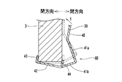
以上のような前枠3側の構成に対して、下枠材2の上面2aには、図2に示すように、前枠3を閉じたときに乗り上げ手段60に対応する位置に誘導部材50が着脱自在に取り付けられている。この誘導部材50が誘導手段の一例である。誘導部材50は、図6に示すように、下枠材2の上面2aに沿う平板状の上片部51と、上片部51から下枠材2の上面2aの前縁部において斜め下向きに延設された誘導片部52(案内部の一例)とを備えており、例えば1枚の金属板を板金処理することにより一体成形されている。上片部51には、当該誘導部材50を下枠材2の上面2aに固定するための木ねじを挿通させる挿通孔51aが穿設されている。また、誘導片部52の上面52aは、下枠材2の上面2aに対する角度が例えば60度程度の斜面を形成している(図6参照)。尚、誘導部材50は、その横幅(下枠材2の長手方向に沿った長さ)が、例えば発射装置13の取付板39の横幅と同程度か、或いは若干長めとなるように形成されている。
【0020】
続いて、上述した乗り上げ手段60を有する発射装置13及び誘導部材50を、前枠3及び下枠材2へそれぞれ取り付ける際の手順を簡単に説明する。まず、発射装置13を前枠3に取り付ける際には、まず発射ハンドル35を除く他の構成部品を取付板39に取り付けた状態で、この取付板39を前枠3の下部の所定位置に取り付ける。例えば、前枠3のヒンジ部4と反対側の開閉端側下端部の所定の取り付け位置において、掛止め片部43を前枠3の裏面側から前面側下縁部に引っ掛ける(図7に実線で示す)。そして、図7に矢印Yで示すように、支持片部40が前枠3の裏面側に当接するまで取付板39を回動させる。
【0021】
これにより、取付板39は、図7に二点鎖線で示すように、乗り上げ手段60を構成する掛止め片部43、下片部42、位置決め片部44、及び支持片部40がそれぞれ前枠3の対応する面に当接した状態となる。このとき、下斜面片41bは前枠3の裏面側に位置し、後方斜め上向きの斜面を形成する。尚、取付板39の前面(前枠3への取り付け面)側に取り付けられている発射バネ32や取り付けボス部36(図4参照)は、前枠3に形成されている図示しない貫通孔内に格納される。この状態で、支持片部40の挿通孔40aに木ねじを挿通して前枠3の裏面にねじ込めば、取付板39は前枠3に固定される。更に、発射ハンドル35を前枠3の前面側から上記貫通孔を介して取り付けボス部36に取り付ける。これで乗り上げ手段60を有する発射装置13の前枠3への取り付けは完了する。
【0022】
また、誘導部材50を下枠材2に取り付ける際には、誘導片部52が下枠材2の前面側斜め下向きとなるように、下枠材2の上面2a上の所定位置(前枠3を閉じたときの取付板39の位置に対応する位置)に誘導部材50の上片部51を当接させる。このとき、上片部51と誘導片部52との間の曲折部を、下枠材2の前縁に合わせるようにして位置決めを行えばよい。この状態で、上片部51の挿通孔51aに木ねじを挿通して下枠材2の上面2aにねじ込めば、誘導部材50は下枠材2の上面に固定される。これで、誘導部材50の下枠材2への取り付けは完了する。
【0023】
続いて、乗り上げ手段60と誘導部材50とが取り付けられた状態での、前枠3の開閉時の動作状態について説明する。図2に示すような開放状態から前枠3を閉じる際には、前枠3はヒンジ部4,4を中心として揺動し、最終的に下枠材2の上側に隣接する位置に到達する。このとき、前枠3の下面3aと下枠材2の上面2aとは対向した状態となる。
【0024】
ここで、上述したように前枠3には各種部品が多数取り付けられているため、その重量は極めて大きい。従って、前枠3を開閉する際にはヒンジ部4に過大な荷重が作用することとなる。その結果、日常的な前枠の開閉を長期間にわたって繰り返すうちにヒンジ部4の取り付けガタ等が次第に大きくなり、前枠3の開閉端側がヒンジ端側よりも相対的に垂れ下がった状態となることが多い。
【0025】
このような状態で前枠3を閉じる際には、図8に示すように、前枠3が完全に閉状態となる直前に、乗り上げ手段60の乗り上げ片部41の下斜面片41bが、誘導部材50の誘導片部52に当接する。その状態から更に前枠3を閉じていくと、下斜面片41bの下面41baが誘導片部52上を摺動し、乗り上げ手段60及び前枠3は、下斜面片41bの下面41baの斜面方向に徐々に持ち上げられる。そして、乗り上げ手段60が誘導部材50に完全に乗り上げた後は、乗り上げ手段60の下片部42が誘導部材50の上片部51上を摺動し、それに伴って前枠3は閉位置まで移動する。
【0026】
このように、前枠3を閉じる際に、乗り上げ手段60の下斜面片41bが誘導部材50上に徐々に乗り上げるため、前枠3の開閉端側がヒンジ端側よりも相対的に垂れ下がった状態となっている場合でも、前枠3の下面3aと下枠材2の上面との干渉による衝撃が極めて小さくなり、前枠3の閉動作を常にスムーズに行うことが可能となる。
【0027】
一方、閉状態にある前枠3を開く場合には、上述した閉動作の場合とは全く逆の動きとなる。即ち、閉状態から前枠3を開いていくと、乗り上げ手段60の下片部42が誘導部材50の上片部51上を摺動した後、下斜面片41bの下面41baが誘導片部52上を摺動しつつ、取付板39及び前枠3は下斜面片41bの下面41baの斜面方向に徐々に降下する。
【0028】
これにより、前枠3の開閉端側がヒンジ端側よりも相対的に垂れ下がった状態となっている場合であっても、前枠3の開動作時には、乗り上げ手段60の下斜面片41bが誘導部材50上を摺動しつつ徐々に降下するため、前枠3の開閉端側が下枠材2から瞬間的に落下することを防止でき、前枠3の開動作を常にスムーズに行うことが可能となる。
【0029】
また以上のように、前枠3の開閉を大きな衝撃を伴うことなく常にスムーズに行うことができることにより、前枠3に取り付けられている各部品が前枠3の開閉時の衝撃によって破損するなどの不具合も解消される。
【0030】
また、乗り上げ手段60は、前枠3上のヒンジ部4とは反対側の開閉端部近傍に取り付けられる発射装置13上に設けられており、ヒンジ部4と乗り上げ手段60のそれぞれの取り付け位置の間には十分に距離があるため、前枠3の開閉時に、乗り上げ手段60やこれと摺動する誘導部材50に作用する力が最小限に抑えられ、これら乗り上げ手段60や誘導部材50を長寿命化できる等の利点もある。但し、ヒンジ部4を、必ず前枠3における発射装置13の取り付け位置と反対側の端部に設けなければならないということではなく、ヒンジ部4と発射装置13とを共に前枠3の片側端部近傍に設けてもよい。
【0031】
また、乗り上げ手段60を発射装置13の取付板39と一体成形しているため、乗り上げ手段を発射装置13とは別個に設ける場合と比べて部品点数を少なくできると共に、組立工程も簡素化できる。
【0032】
図9は、本発明の第2の実施形態を例示し、乗り上げ手段61(支持片部40、乗り上げ片部41、下片部42、掛止め片部43、及び位置決め片部44)を、取付板39′とは別部材として形成し、取付板39′にネジ止めや溶接等によって固定した例を示している。このように、乗り上げ手段61と取付板39′とを別部材とすることにより、例えば乗り上げ手段61を取り付ける機種と取り付けない機種とで取付板39′を共通化できる等の利点がある。
【0033】
図10及び図11は、本発明の第3の実施形態を例示し、発射装置13″の取付板39″に例えば一体形成された車輪支持部53と、該車輪支持部53に対して横軸54a廻りに回動自在の車輪54とで乗り上げ手段62を構成した例を示している。尚、車輪支持部53は、取付板39″とは別部材として形成し、取付板39″にネジ止めや溶接等で固定するようにしてもよい。また、車輪54は、図11に示すように、例えばその最下部(底面)の位置が、前枠3の下面3aと略同一の高さか若しくは若干低くなるように取り付けられている。
【0034】
この乗り上げ手段62を取り付けた状態で前枠3を閉じる際には、図11に示すように、前枠3が完全に閉状態となる直前に、車輪54が誘導部材50の誘導片部52に当接する。その状態から更に前枠3を閉じていくと、車輪54が誘導片部52の斜面に乗り上げるように転動し、乗り上げ手段62及び前枠3は斜め上方に向けて徐々に持ち上げられる。そして、乗り上げ手段62が誘導部材50上に完全に乗り上げた後は、車輪54が誘導部材50の上片部51上を水平に転動し、やがて誘導部材50の上片部51の後端側において車輪54は誘導部材50から外れる。その後は、前枠3の下面3aが誘導部材50の上片部51上を水平に摺動しつつ閉位置まで移動する。また、閉状態にある前枠3を開く場合には、以上の閉動作の場合と全く逆の動きとなる。
【0035】
このように、車輪54を有する乗り上げ手段62を用いても、上述した第1,第2の実施形態の場合と同様、前枠3の開閉端側がヒンジ端側よりも相対的に垂れ下がった状態となっている場合であっても、前枠3の開閉動作を大きな衝撃を伴うことなく常にスムーズに行うことが可能であり、前枠3に取り付けられている各部品が前枠3の開閉時の衝撃によって破損するなどの不具合も解消できる。
【0036】
以上、本発明の実施形態について詳述したが、本発明はこの実施形態に限定されるものではなく、本発明の趣旨を逸脱しない範囲で種々の変更が可能である。例えば、取付板39をアルミ系合金等の材料で鋳造する場合には、乗り上げ手段60をこの取付板39と一体的に鋳造することも可能である。また、乗り上げ手段60を例えば鉄などの別材料で板金により成形し、これを取付板39の鋳造時にモールドにより一体化したり、或いは鋳造した取付板39にネジ止め等で固定することも可能である。
【0037】
また、第1及び第2の実施形態では、取付板39の下縁部全体にわたって乗り上げ手段60,61を形成した例を示したが、これに限られるものではなく、取付板39の下縁部の一部分にのみ乗り上げ手段60,61を形成してもよい。
【0038】
また、第1及び第2の実施形態では、乗り上げ手段60,61が掛止め片部43や位置決め片部44を備えた例を示したが、これらのいずれか若しくは両方を省略することも可能である。また、下片部42は、必ずしも前枠3の下面3aに当接させる必要はなく、両者間に若干の距離を設けてもよい。
【0039】
また、第1及び第2の実施形態では、乗り上げ手段60,61と誘導部材50の両方に屈曲状の案内部(乗り上げ片部41の下斜面片41bと誘導片部52)を形成した例を示したが、これら案内部は、乗り上げ手段60,61と誘導部材50のいずれか一方のみに設けてもよい。
【0040】
その他、本発明は、パチンコ機だけでなくアレンジボール機や雀球遊技機等の弾球遊技機においても同様に実施可能である。
【0041】
【発明の効果】
以上説明したように,本発明は,矩形状の外枠1 と、該外枠1 に縦軸廻りに揺動開閉可能に取り付けられる前枠3 と、上記外枠1 の下部に取り付けられ、その上面2aが上記前枠3 を閉じた状態で上記前枠3 の下面3aと対向する下枠材2 と、上記前枠3 の下部に取り付けられ、上記前枠3 に取り付けられた遊技盤6 に向けて遊技球を発射する発射装置13,13',13"とを備えた弾球遊技機において、上記前枠3 を閉じる際に該前枠3 の下面3aを上記下枠材2 の上面2aに乗り上げさせる乗り上げ手段60,61 を備え、この乗り上げ手段60,61 は、上記前枠3 の裏面側に沿って装着される支持片部40と、この支持片部40の下縁部から上記前枠3 の背面側に向けて突出する断面くの字状に形成された乗り上げ片部41と、この乗り上げ片部41から上記前枠3 の下面3aに沿って前面側に向けて延設された下片部42と、該下片部 42 側の一部分が上記乗り上げ片部 41 と上記下片部 42 との境界線に沿って上記前枠 3 の裏面側に沿うように上向きに曲げ起こされて形成された位置決め片部 44 とを備えているため、外枠1 に対する前枠3 の開閉を常にスムーズに行うことが可能となる。
【図面の簡単な説明】
【図1】本発明の第1の実施形態を示すパチンコ機の正面図である。
【図2】本発明の第1の実施形態を示すパチンコ機の前枠を開いた状態を示す斜視図である。
【図3】本発明の第1の実施形態を示すパチンコ機の発射装置近傍の拡大斜視図である。
【図4】本発明の第1の実施形態を示す発射装置の構造図である。
【図5】本発明の第1の実施形態を示す発射装置の乗り上げ手段近傍の拡大斜視図である。
【図6】本発明の第1の実施形態を示す誘導部材の拡大斜視図である。
【図7】本発明の第1の実施形態を示す発射装置の前枠への装着方法を示す説明図である。
【図8】本発明の第1の実施形態を示す前枠の開閉時における乗り上げ手段と誘導部材との動作状態を示す説明図である。
【図9】本発明の第2の実施形態を示すパチンコ機の発射装置近傍の拡大斜視図である。
【図10】本発明の第3の実施形態を示すパチンコ機の発射装置近傍の拡大斜視図である。
【図11】本発明の第3の実施形態を示す前枠の開閉時における乗り上げ手段と誘導部材との動作状態を示す説明図である。
【符号の説明】
1 外枠
2 下枠材
2a 下枠材上面
3 前枠
3a 前枠下面
6 遊技盤
13 発射装置
13′ 発射装置
31 打撃槌
34 駆動モータ(駆動手段)
35 発射ハンドル(操作手段)
39 取付板
39′ 取付板
40 支持片部
41 乗り上げ片部
41a 上斜面片
41b 下斜面片
41ba 下斜面片下面
42 下片部
50 誘導部材(誘導手段)
51 上片部
52 誘導片部
53 車輪支持部
54 車輪
60 乗り上げ手段
61 乗り上げ手段
62 乗り上げ手段[0001]
BACKGROUND OF THE INVENTION
The present invention relates to a ball game machine such as a pachinko machine in which a front frame on which a game board or the like is installed is attached to the front side of a rectangular outer frame so as to be swingable and openable around a vertical axis. .
[0002]
[Prior art]
In ball game machines such as pachinko machines and arrange ball machines, the front frame is attached to the front side of the rectangular outer frame in a state that can swing and open around the vertical axis, and further, on the lower front side of the outer frame, In general, when the front frame is closed, the lower frame material is fixed so as to be adjacent to the lower portion of the front frame.
[0003]
The front frame has a game board with various winning means, display means, etc. attached to the back side of the front frame, a back mechanism plate for detachably fixing the game board to the front frame, various control boards, switches, etc. In addition, on the front side, there is a glass door that covers the front side of the game board, a front plate fitted with an upper plate that stores game balls, a lower plate that stores excess balls, and game balls as game boards A launching device or the like for launching is attached.
[0004]
In the ball game machine having the above-described configuration, by closing the front frame, the lower surface of the front frame and the upper surface of the outer frame are opposed to each other, and the front side of the outer frame is formed by the front frame and the lower frame material. It is in a completely blocked state.
[0005]
[Problems to be solved by the invention]
By the way, as mentioned above, since many various parts are attached to the front frame, the weight is very large. Therefore, when the front frame is opened and closed, an excessive load acts on the hinge portion that supports the front frame so that it can be opened and closed. As a result, as the routine opening and closing of the front frame is repeated over a long period of time, the mounting backlash etc. of the hinge part gradually increases, and the opening and closing end side of the front frame may be in a state where it hangs relative to the hinge end side. Many. In such a state, the upper surface of the lower frame material and the lower surface of the front frame interfere with each other, and not only the front frame can be opened and closed smoothly, but also each of the frames attached to the front frame, for example, due to an impact generated at the time of opening and closing There was also a risk of adversely affecting the parts.
[0006]
The present invention has been made in view of the above circumstances, and an object of the present invention is to provide a ball game machine capable of always opening and closing the front frame smoothly.
[0007]
[Means for Solving the Problems]
In order to achieve the above object, the present invention is attached to a rectangular outer frame 1, a
[0008]
DETAILED DESCRIPTION OF THE INVENTION
Hereinafter, an embodiment in which a ball game machine according to the present invention is embodied as a pachinko machine will be described with reference to the drawings. 1 to 8 illustrate a first embodiment of the present invention. In FIGS. 1 and 2, reference numeral 1 denotes a rectangular outer frame, and a
[0009]
A
[0010]
In addition, a
[0011]
A
[0012]
Further, the
[0013]
When the player touches the
[0014]
In the present embodiment, as shown in FIG. 4, all the parts other than the mounting
[0015]
In addition, although the launching
[0016]
Further, as shown in FIGS. 3 and 5, riding means 60 is formed in the lower portion of the mounting
[0017]
The
[0018]
In addition, the
[0019]
In contrast to the configuration on the
[0020]
Then, the procedure at the time of attaching the
[0021]
As a result, as shown in FIG. 7 by a two-dot chain line, the mounting
[0022]
Further, when the
[0023]
Next, an operation state at the time of opening and closing the
[0024]
Here, as described above, a large number of various parts are attached to the
[0025]
When the
[0026]
In this way, when the
[0027]
On the other hand, when the
[0028]
As a result, even when the opening / closing end side of the
[0029]
In addition, as described above, the opening and closing of the
[0030]
Further, the ride-on means 60 is provided on the
[0031]
Further, since the climbing means 60 is integrally formed with the mounting
[0032]
FIG. 9 exemplifies the second embodiment of the present invention, and mounts the climbing means 61 (
[0033]
10 and 11 illustrate a third embodiment of the present invention. For example, a
[0034]
When the
[0035]
As described above, even when the ride-up means 62 having the
[0036]
As mentioned above, although embodiment of this invention was explained in full detail, this invention is not limited to this embodiment, A various change is possible in the range which does not deviate from the meaning of this invention. For example, when the mounting
[0037]
Further, in the first and second embodiments, the example in which the riding means 60 and 61 are formed over the entire lower edge of the mounting
[0038]
Further, in the first and second embodiments, the example in which the ride-on means 60, 61 includes the latching
[0039]
Further, in the first and second embodiments, an example in which bent guide portions (the
[0040]
In addition, the present invention can be similarly implemented not only in pachinko machines but also in ball game machines such as arrange ball machines and sparrow ball game machines.
[0041]
【The invention's effect】
As described above, the present invention has a rectangular outer frame 1, a
[Brief description of the drawings]
FIG. 1 is a front view of a pachinko machine showing a first embodiment of the present invention.
FIG. 2 is a perspective view showing a state in which a front frame of the pachinko machine according to the first embodiment of the present invention is opened.
FIG. 3 is an enlarged perspective view of the vicinity of the launching device of the pachinko machine showing the first embodiment of the present invention.
FIG. 4 is a structural diagram of a launching apparatus showing a first embodiment of the present invention.
FIG. 5 is an enlarged perspective view of the vicinity of the ride-on means of the launching apparatus showing the first embodiment of the present invention.
FIG. 6 is an enlarged perspective view of the guide member showing the first embodiment of the present invention.
FIG. 7 is an explanatory diagram showing a method for mounting the launching device to the front frame according to the first embodiment of the present invention.
FIG. 8 is an explanatory view showing an operating state of the ride-up means and the guide member when the front frame is opened and closed according to the first embodiment of the present invention.
FIG. 9 is an enlarged perspective view of the vicinity of a launching device of a pachinko machine showing a second embodiment of the present invention.
FIG. 10 is an enlarged perspective view of the vicinity of a launching device of a pachinko machine showing a third embodiment of the present invention.
FIG. 11 is an explanatory view showing an operating state of the ride-up means and the guide member when the front frame is opened and closed according to the third embodiment of the present invention.
[Explanation of symbols]
DESCRIPTION OF SYMBOLS 1
35 Launch handle (operating means)
39
51
Claims (6)
上記前枠(3) を閉じる際に該前枠(3) の下面(3a)を上記下枠材(2) の上面(2a)に乗り上げさせる乗り上げ手段(60)(61)を備え、この乗り上げ手段(60)(61)は、上記前枠(3) の裏面側に沿って装着される支持片部(40)と、この支持片部(40)の下縁部から上記前枠(3) の背面側に向けて突出する断面くの字状に形成された乗り上げ片部(41)と、この乗り上げ片部(41)から上記前枠(3) の下面(3a)に沿って前面側に向けて延設された下片部(42)と、該下片部 (42) 側の一部分が上記乗り上げ片部 (41) と上記下片部 (42) との境界線に沿って上記前枠 (3) の裏面側に沿うように上向きに曲げ起こされて形成された位置決め片部 (44) とを備えていることを特徴とする弾球遊技機。A rectangular outer frame (1), a front frame (3) attached to the outer frame (1) so as to be swingable and openable around the vertical axis, and an upper surface ( 2a) is attached to the lower frame material (2) facing the lower surface (3a) of the front frame (3) with the front frame (3) closed, and to the lower part of the front frame (3). In a ball game machine equipped with a launcher (13) (13 ') (13'') that launches a game ball toward a game board (6) attached to the frame (3),
When the front frame (3) is closed, it is provided with riding means (60) (61) for riding the lower surface (3a) of the front frame (3) onto the upper surface (2a) of the lower frame material (2). The means (60) (61) includes a support piece (40) mounted along the back side of the front frame (3), and the front frame (3) from the lower edge of the support piece (40). A riding piece (41) formed in a cross-sectional shape that protrudes toward the back side of the frame, and from the riding piece (41) to the front side along the lower surface (3a) of the front frame (3) A lower piece portion (42) extending toward the lower piece portion (42) and a portion of the lower piece portion (42) side along the boundary line between the riding piece portion (41) and the lower piece portion (42). pinball game machine, characterized in that it comprises upward bent awakened positioning piece portion formed by the (44) along the back side of (3).
上記乗り上げ手段(60)(61)を上記取付板(39)(39')(39")に設けたことを特徴とする請求項1〜3のいずれかに記載の弾球遊技機。The launching device (13) (13 ′) (13 ″) includes a striking rod (31) for striking a game ball toward the game board (6), and driving means (34) for driving the striking rod (31). ), An operating means (35) provided forwardly projecting from the front frame (3) and capable of adjusting the striking force of the striking gutter (31), and the striking gutter (31), driving means (34 ), And a mounting plate (39) (39 ') (39'') for fixing the operating means (35) to the front frame (3),
The ball game machine according to any one of claims 1 to 3, wherein the ride-on means (60) (61) is provided on the mounting plate (39) (39 ') (39 ").
Priority Applications (1)
| Application Number | Priority Date | Filing Date | Title |
|---|---|---|---|
| JP2000280233A JP3801431B2 (en) | 2000-09-14 | 2000-09-14 | Bullet ball machine |
Applications Claiming Priority (1)
| Application Number | Priority Date | Filing Date | Title |
|---|---|---|---|
| JP2000280233A JP3801431B2 (en) | 2000-09-14 | 2000-09-14 | Bullet ball machine |
Publications (2)
| Publication Number | Publication Date |
|---|---|
| JP2002085762A JP2002085762A (en) | 2002-03-26 |
| JP3801431B2 true JP3801431B2 (en) | 2006-07-26 |
Family
ID=18765114
Family Applications (1)
| Application Number | Title | Priority Date | Filing Date |
|---|---|---|---|
| JP2000280233A Expired - Fee Related JP3801431B2 (en) | 2000-09-14 | 2000-09-14 | Bullet ball machine |
Country Status (1)
| Country | Link |
|---|---|
| JP (1) | JP3801431B2 (en) |
Families Citing this family (8)
| Publication number | Priority date | Publication date | Assignee | Title |
|---|---|---|---|---|
| JP4530331B2 (en) * | 2003-09-08 | 2010-08-25 | サミー株式会社 | Sparrow ball machine |
| JP2006026317A (en) * | 2004-07-21 | 2006-02-02 | Samii Kk | Vertical game machine |
| JP2006181003A (en) * | 2004-12-27 | 2006-07-13 | Samii Kk | Locking device of pinball game machine |
| JP2007175195A (en) * | 2005-12-27 | 2007-07-12 | Heiwa Corp | Game machine |
| JP4915742B2 (en) * | 2007-08-03 | 2012-04-11 | サミー株式会社 | Fraud prevention structure |
| JP5125884B2 (en) * | 2008-08-26 | 2013-01-23 | 奥村遊機株式会社 | Pachinko machine game board unit |
| JP5713059B2 (en) * | 2013-07-12 | 2015-05-07 | 株式会社三洋物産 | Game machine |
| JP6603901B2 (en) * | 2017-11-28 | 2019-11-13 | 株式会社大都技研 | Amusement stand |
-
2000
- 2000-09-14 JP JP2000280233A patent/JP3801431B2/en not_active Expired - Fee Related
Also Published As
| Publication number | Publication date |
|---|---|
| JP2002085762A (en) | 2002-03-26 |
Similar Documents
| Publication | Publication Date | Title |
|---|---|---|
| JP3801431B2 (en) | Bullet ball machine | |
| JP4299284B2 (en) | Movable body drive mechanism and movable body device of pachinko machine | |
| JP5506046B2 (en) | Prize-winning device for bullet ball machines | |
| JPH1133171A (en) | Ball game machine | |
| JP5136445B2 (en) | Pachinko machine | |
| JP4335826B2 (en) | Bullet ball machine | |
| JP4180336B2 (en) | Bullet ball machine | |
| JP4401313B2 (en) | Bullet ball machine | |
| JP2013034602A (en) | Pachinko game machine | |
| JPH06304302A (en) | Pinball game machine | |
| JPH06233858A (en) | Pachinko machine | |
| JP4919417B2 (en) | Frame structure and gaming machine | |
| JP2514080Y2 (en) | Ball guide device for pachinko machines | |
| JP3742307B2 (en) | Bullet ball machine | |
| JPH0341739Y2 (en) | ||
| JP2504394Y2 (en) | Windmill device in pachinko machine | |
| JP4656554B2 (en) | Bullet ball machine | |
| JP6778425B2 (en) | Game machine | |
| JP2020203197A (en) | Game machine | |
| JP4327141B2 (en) | Pachinko machine and its swing mechanism | |
| JP6030678B2 (en) | Game machine | |
| JP4705965B2 (en) | Game machine | |
| JP5689775B2 (en) | Game machine | |
| JP4722160B2 (en) | Bullet ball machine | |
| JP4493898B2 (en) | Bullet ball machine |
Legal Events
| Date | Code | Title | Description |
|---|---|---|---|
| A131 | Notification of reasons for refusal |
Free format text: JAPANESE INTERMEDIATE CODE: A131 Effective date: 20041214 |
|
| A521 | Written amendment |
Free format text: JAPANESE INTERMEDIATE CODE: A523 Effective date: 20050204 |
|
| A131 | Notification of reasons for refusal |
Free format text: JAPANESE INTERMEDIATE CODE: A131 Effective date: 20051018 |
|
| A521 | Written amendment |
Free format text: JAPANESE INTERMEDIATE CODE: A523 Effective date: 20051216 |
|
| TRDD | Decision of grant or rejection written | ||
| A01 | Written decision to grant a patent or to grant a registration (utility model) |
Free format text: JAPANESE INTERMEDIATE CODE: A01 Effective date: 20060425 |
|
| A61 | First payment of annual fees (during grant procedure) |
Free format text: JAPANESE INTERMEDIATE CODE: A61 Effective date: 20060425 |
|
| R150 | Certificate of patent or registration of utility model |
Free format text: JAPANESE INTERMEDIATE CODE: R150 |
|
| FPAY | Renewal fee payment (event date is renewal date of database) |
Free format text: PAYMENT UNTIL: 20090512 Year of fee payment: 3 |
|
| FPAY | Renewal fee payment (event date is renewal date of database) |
Free format text: PAYMENT UNTIL: 20100512 Year of fee payment: 4 |
|
| FPAY | Renewal fee payment (event date is renewal date of database) |
Free format text: PAYMENT UNTIL: 20100512 Year of fee payment: 4 |
|
| FPAY | Renewal fee payment (event date is renewal date of database) |
Free format text: PAYMENT UNTIL: 20110512 Year of fee payment: 5 |
|
| FPAY | Renewal fee payment (event date is renewal date of database) |
Free format text: PAYMENT UNTIL: 20120512 Year of fee payment: 6 |
|
| FPAY | Renewal fee payment (event date is renewal date of database) |
Free format text: PAYMENT UNTIL: 20130512 Year of fee payment: 7 |
|
| FPAY | Renewal fee payment (event date is renewal date of database) |
Free format text: PAYMENT UNTIL: 20130512 Year of fee payment: 7 |
|
| FPAY | Renewal fee payment (event date is renewal date of database) |
Free format text: PAYMENT UNTIL: 20140512 Year of fee payment: 8 |
|
| R250 | Receipt of annual fees |
Free format text: JAPANESE INTERMEDIATE CODE: R250 |
|
| R250 | Receipt of annual fees |
Free format text: JAPANESE INTERMEDIATE CODE: R250 |
|
| R250 | Receipt of annual fees |
Free format text: JAPANESE INTERMEDIATE CODE: R250 |
|
| R250 | Receipt of annual fees |
Free format text: JAPANESE INTERMEDIATE CODE: R250 |
|
| LAPS | Cancellation because of no payment of annual fees |