JP4530203B2 - Redox potentiometer - Google Patents
Redox potentiometer Download PDFInfo
- Publication number
- JP4530203B2 JP4530203B2 JP2004151750A JP2004151750A JP4530203B2 JP 4530203 B2 JP4530203 B2 JP 4530203B2 JP 2004151750 A JP2004151750 A JP 2004151750A JP 2004151750 A JP2004151750 A JP 2004151750A JP 4530203 B2 JP4530203 B2 JP 4530203B2
- Authority
- JP
- Japan
- Prior art keywords
- voltage
- electrode
- reduction
- oxidation
- reduction circuit
- Prior art date
- Legal status (The legal status is an assumption and is not a legal conclusion. Google has not performed a legal analysis and makes no representation as to the accuracy of the status listed.)
- Expired - Fee Related
Links
Images


Classifications
-
- G—PHYSICS
- G01—MEASURING; TESTING
- G01N—INVESTIGATING OR ANALYSING MATERIALS BY DETERMINING THEIR CHEMICAL OR PHYSICAL PROPERTIES
- G01N27/00—Investigating or analysing materials by the use of electric, electrochemical, or magnetic means
- G01N27/26—Investigating or analysing materials by the use of electric, electrochemical, or magnetic means by investigating electrochemical variables; by using electrolysis or electrophoresis
- G01N27/416—Systems
- G01N27/4166—Systems measuring a particular property of an electrolyte
- G01N27/4168—Oxidation-reduction potential, e.g. for chlorination of water
Description
本発明は、生活用水、工業用水、自然水、科学的溶液等のあらゆる水分を対象として、その酸化還元電位を便利で正確に測定する酸化還元電位計に関する。 The present invention relates to an oxidation-reduction potentiometer that conveniently and accurately measures the oxidation-reduction potential of all types of water such as domestic water, industrial water, natural water, and scientific solutions.
昨今、白金(Pt)又は金(Au)などの貴金属からなる作用電極と、塩化ナトリウム(NaCl)又は塩化カリウム(KCl)などからなりゲル状又は液状である内部液に銀(Ag)及び塩化銀(AgCl)からなる金属部が浸水して成る参照電極とを被験液に浸け、その際、酸化還元反応によって発生する作用電極と参照電極の間の電圧を測定する酸化還元電位計が提供され又は開示されている。 Recently, silver (Ag) and silver chloride are added to a working electrode made of a noble metal such as platinum (Pt) or gold (Au), and an internal liquid made of sodium chloride (NaCl) or potassium chloride (KCl) or the like in a gel or liquid state. An oxidation-reduction potentiometer is provided for measuring a voltage between the working electrode and the reference electrode generated by the oxidation-reduction reaction, by immersing a reference electrode in which a metal part made of (AgCl) is immersed in the test solution, or It is disclosed.
かかる酸化還元電位計は、作用電極と参照電極の間の電圧、すなわち、作用電極に発生する電位と参照電極に発生する電位との差をそのまま保ちつつ、増幅やA/D変換等の過程を経て、酸化還元電位値として示すものである(例えば、特許文献1又は特許文献2参照)。
Such an oxidation-reduction potentiometer keeps the difference between the voltage between the working electrode and the reference electrode, that is, the potential generated at the working electrode and the potential generated at the reference electrode, while maintaining the process such as amplification and A / D conversion. Then, it shows as an oxidation-reduction potential value (for example, refer
しかしながら、かかる酸化還元電位計は、金属による電極と被験液との反応の不安定さに拠るところから、電極に発生する電位のある物質濃度の非直線性及び繰り返し性に劣り、かつ、測定時間を要するといった問題があった。 However, such an oxidation-reduction potentiometer is based on the instability of the reaction between the electrode and the test solution due to the metal, so that the non-linearity and repeatability of the substance concentration with potential generated at the electrode is inferior, and the measurement time There was a problem that required.
そこで、本発明は、このような従来の問題点を解決することを目的とするもので、測定精度の向上、測定時間の短縮化等の利便性を高めた酸化還元電位計を提供することを目的とする。 Accordingly, the present invention aims to solve such conventional problems, and provides an oxidation-reduction potentiometer with improved convenience such as improvement in measurement accuracy and reduction in measurement time. Objective.
本発明の酸化還元電位計は、液に浸けた際に酸化還元反応の程度を示す電位が発生する作用電極と、前記液に浸けた際に基準となる電位が発生する参照電極と、前記液に浸けた際における前記作用電極と前記参照電極との間に生ずるインピーダンスを低減するインピーダンス低減回路と、前記インピーダンス低減回路によりインピーダンスを低減する際における前記作用電極により発生する酸化還元反応の程度を表す電位と前記参照電極により発生する基準となる電位との差である電極間電圧に基づいて酸化還元電位を測定する酸化還元電位測定手段と、を備えることを特徴とする。 The oxidation-reduction potentiometer of the present invention comprises a working electrode that generates a potential indicating the degree of redox reaction when immersed in a liquid, a reference electrode that generates a reference potential when immersed in the liquid, and the liquid Represents an impedance reduction circuit that reduces the impedance generated between the working electrode and the reference electrode when immersed in the electrode, and a degree of redox reaction generated by the working electrode when the impedance is reduced by the impedance reduction circuit And oxidation-reduction potential measuring means for measuring an oxidation-reduction potential based on a voltage between electrodes which is a difference between a potential and a reference potential generated by the reference electrode.
また、前記酸化還元電位測定手段は、前記作用電極と前記参照電極との間に前記インピーダンス低減回路を非接続状態及び接続状態へと切替える低減回路切替手段と、前記低減回路切替手段により前記インピーダンス低減回路を非接続状態及び接続状態へと切替えた際における前記作用電極により発生する酸化還元反応の程度を表す電位と前記参照電極により発生する基準となる電位との差である電極間電圧を測定する電極間電圧測定手段と、前記電極間電圧測定手段により測定した非接続状態及び接続状態における電極間電圧に基づいて対比係数を演算する対比係数演算部と、前記対比係数演算部により演算した対比係数を記憶する対比係数記憶部と、前記低減回路切替手段により前記インピーダンス低減回路を接続状態へと切替えた際に前記電極間電圧測定手段により測定した接続状態における電極間電圧と、前記対比係数記憶部に記憶した対比係数とに基づいて酸化還元電位を演算する酸化還元電位演算部と、から成ることを特徴とする。 Further, the oxidation-reduction potential measuring means includes a reduction circuit switching means for switching the impedance reduction circuit between the working electrode and the reference electrode to a non-connected state and a connected state, and the impedance reduction by the reduction circuit switching means. Measure an inter-electrode voltage that is a difference between a potential representing the degree of oxidation-reduction reaction generated by the working electrode and a reference potential generated by the reference electrode when the circuit is switched between a disconnected state and a connected state. Inter-electrode voltage measuring means, a contrast coefficient computing section for computing a contrast coefficient based on the inter-electrode voltage in the non-connected state and connected state measured by the inter-electrode voltage measuring means, and a contrast coefficient computed by the contrast coefficient computing section When the impedance reduction circuit is switched to the connected state by the comparison coefficient storage unit for storing And an oxidation-reduction potential calculation unit that calculates an oxidation-reduction potential based on the inter-electrode voltage in the connected state measured by the inter-electrode voltage measurement means and the comparison coefficient stored in the comparison coefficient storage unit. To do.
また、前記液の導電率を測定する導電率測定手段と、前記電極間電圧測定手段による電極間電圧の測定と前記導電率測定手段による導電率の測定とを切替える導電率測定切替手段を更に備え、前記対比係数記憶部は、前記導電率測定切替手段による電極間電圧の測定と導電率の測定との切替えに基づいて前記対比係数演算部により演算した導電率の異なる各液に対する各対比係数を記憶し、前記酸化還元電位演算部は、前記低減回路切替手段により前記インピーダンス低減回路を接続状態へと切替えた際に前記電極間電圧測定手段により測定した接続状態における電極間電圧と、前記対比係数記憶部に記憶した導電率の異なる各液に対する各対比係数のうちから前記導電率測定手段により測定された液の導電率に対応する対比係数とに基づいて酸化還元電位を演算する、ことを特徴とする。 And a conductivity measuring means for measuring the conductivity of the liquid; and a conductivity measuring switching means for switching between the measurement of the interelectrode voltage by the interelectrode voltage measuring means and the measurement of the conductivity by the conductivity measuring means. The contrast coefficient storage unit stores each contrast coefficient for each liquid having a different conductivity calculated by the contrast coefficient calculation unit based on switching between the measurement of the voltage between the electrodes and the measurement of the conductivity by the conductivity measurement switching unit. And storing the oxidation-reduction potential calculation unit, the inter-electrode voltage in the connection state measured by the inter-electrode voltage measurement unit when the impedance reduction circuit is switched to the connection state by the reduction circuit switching unit, and the contrast coefficient. Based on the contrast coefficient corresponding to the electrical conductivity of the liquid measured by the electrical conductivity measuring means from among the respective contrast coefficients for the liquids having different electrical conductivities stored in the storage unit. It calculates the redox potential, characterized in that.
また、前記酸化還元電位測定手段により酸化還元電位を測定する段階前に、前記作用電極と前記参照電極とが前記液に浸かっていることを測定する水没測定手段を更に備え、 前記低減回路切替手段は、前記水没測定手段による測定の間、前記インピーダンス低減回路を非接続状態へと切替えている、ことを特徴とする。 In addition, before the step of measuring the oxidation-reduction potential by the oxidation-reduction potential measurement means, the apparatus further comprises submergence measurement means for measuring that the working electrode and the reference electrode are immersed in the liquid, and the reduction circuit switching means Is characterized in that the impedance reduction circuit is switched to a non-connected state during measurement by the submergence measuring means.
前記作用電極は、面積の異なる複数の作用電極から成り、前記面積の異なる複数の作用電極のうちのいずれかの作用電極に前記電極間電圧測定手段との接続を切替える作用電極切替手段を更に備え、前記インピーダンス低減回路は、前記面積の異なる複数の各々の作用電極と前記参照電極との間に生ずるインピーダンスを低減するものであり、前記低減回路切替手段は、前記面積の異なる複数の各々の作用電極と前記参照電極との間に前記インピーダンス低減回路を非接続状態及び接続状態へと切替え、前記電極間電圧測定手段は、前記低減回路切替手段により前記インピーダンス低減回路を非接続状態及び接続状態へと切替えた際における前記面積の異なる複数の各々の作用電極により発生する各酸化還元反応の程度を表す電位と前記参照電極により発生する基準となる電位との差である各電極間電圧を測定し、前記対比係数演算部は、前記電極間電圧測定手段により測定した非接続状態及び接続状態における各電極間電圧に基づいて各対比係数を演算し、前記対比係数記憶部は、前記対比係数演算部により演算した各対比係数を記憶し、前記酸化還元電位演算部は、前記低減回路切替手段により前記面積の異なる複数の各々の作用電極のうちの面積の小さなものから順に前記インピーダンス低減回路を接続状態へと切替えた際に、前記電極間電圧測定手段により測定した接続状態における各電極間電圧と、前記対比係数記憶部に記憶した各対比係数のうちの対応する対比係数とに基づいて酸化還元電位を演算する、ことを特徴とする。 The working electrode includes a plurality of working electrodes having different areas, and further includes working electrode switching means for switching connection of the interelectrode voltage measuring means to any one of the plurality of working electrodes having different areas. The impedance reduction circuit reduces impedance generated between each of the plurality of working electrodes having different areas and the reference electrode, and the reduction circuit switching unit is configured to operate each of the plurality of working electrodes having different areas. The impedance reduction circuit is switched between a non-connected state and a connected state between an electrode and the reference electrode, and the inter-electrode voltage measuring means switches the impedance reduction circuit to a non-connected state and a connected state by the reduction circuit switching means. And the potential representing the degree of each oxidation-reduction reaction generated by each of the plurality of working electrodes having different areas when switching to and the reference Each inter-electrode voltage, which is a difference from the reference potential generated by the pole, is measured, and the contrast coefficient calculation unit is based on the inter-electrode voltage in the non-connected state and the connected state measured by the inter-electrode voltage measuring means. Each contrast coefficient is calculated, the contrast coefficient storage section stores each contrast coefficient calculated by the contrast coefficient calculation section, and the oxidation-reduction potential calculation section has a plurality of areas having different areas by the reduction circuit switching means. Each inter-electrode voltage in the connection state measured by the inter-electrode voltage measuring means when the impedance reduction circuit is switched to the connection state in order from the smallest of the working electrodes, and the contrast coefficient storage unit The oxidation-reduction potential is calculated based on the corresponding contrast coefficient among the respective contrast coefficients stored in (1).
また、前記インピーダンス低減回路は、前記作用電極と前記参照電極との間を低減抵抗だけで接続するものであることを特徴とする。 The impedance reduction circuit connects the working electrode and the reference electrode only with a reduction resistor.
また、前記インピーダンス低減回路は、電圧を生成する電圧生成回路と、前記電圧生成回路に接続するボルテージ・フォロワと、前記ボルテージ・フォロワと前記作用電極との間に接続する出力抵抗とから成ることを特徴とする。 The impedance reduction circuit includes a voltage generation circuit for generating a voltage, a voltage follower connected to the voltage generation circuit, and an output resistor connected between the voltage follower and the working electrode. Features.
また、前記インピーダンス低減回路は、前記作用電極と前記参照電極との間に生ずるインピーダンスを段階的に低減するものであり、前記低減回路切替手段は、前記インピーダンス低減回路を接続状態へと段階的に切替え、前記電極間電圧測定手段は、前記インピーダンス低減回路を接続状態へと段階的に切替えた際における各段階の電極間電圧を測定し、前記対比係数演算部は、前記電極間電圧測定手段により測定した接続状態における各段階の電極間電圧に基づいて各段階の対比係数を演算し、前記対比係数記憶部は、前記対比係数演算部により演算した各段階の対比係数を記憶し、前記酸化還元電位演算部は、前記低減回路切替手段により前記インピーダンス低減回路を接続状態へと各段階のうちの一段階に切替えた際に前記電極間電圧測定手段により測定した接続状態における電極間電圧と、前記対比係数記憶部に記憶した各段階の対比係数のうちの対応する段階の対比係数とに基づいて酸化還元電位値を演算する、ことを特徴とする。 The impedance reduction circuit reduces the impedance generated between the working electrode and the reference electrode in stages, and the reduction circuit switching means steps the impedance reduction circuit into a connected state. The switching, the interelectrode voltage measuring means measures the interelectrode voltage at each stage when the impedance reduction circuit is switched to the connected state stepwise, and the contrast coefficient calculation unit is operated by the interelectrode voltage measuring means. The contrast coefficient of each stage is calculated based on the measured inter-electrode voltage in the connection state, and the contrast coefficient storage unit stores the contrast coefficient of each stage calculated by the contrast coefficient calculation unit, and the redox The potential calculation unit is configured to switch the interelectrode power when the impedance reduction circuit is switched to a connected state in one of the stages by the reduction circuit switching unit. An oxidation-reduction potential value is calculated based on the voltage between the electrodes in the connection state measured by the measuring means and the corresponding comparison coefficient among the comparison coefficients stored in the comparison coefficient storage unit. And
また、前記インピーダンス低減回路は、前記作用電極と前記参照電極との間を複数かつ並列に低減抵抗だけで接続するものであることを特徴とする。 Further, the impedance reduction circuit is characterized in that the working electrode and the reference electrode are connected in plural and in parallel with only a reduction resistor.
また、前記インピーダンス低減回路は、段階的な電圧を生成する電圧生成回路と、前記電圧生成回路に接続するボルテージ・フォロワと、前記ボルテージ・フォロワと前記作用電極との間に接続する出力抵抗とから成ることを特徴とする。 The impedance reduction circuit includes a voltage generation circuit that generates a stepped voltage, a voltage follower connected to the voltage generation circuit, and an output resistor connected between the voltage follower and the working electrode. It is characterized by comprising.
本発明の酸化還元電位計は、作用電極と参照電極とを基準液に浸け、インピーダンス低減回路によりインピーダンスを低減する際における電極間電圧に基づいて酸化還元電位を酸化還元電位測定手段により測定する。また、更に具体的には、作用電極と参照電極とを基準液に浸け、インピーダンス低減回路が作用電極と参照電極との間に非接続状態の際における電極間電圧と接続状態の際における電極間電圧とを電極間電圧測定手段により測定し、これら測定した電極間電圧に基づいて対比係数を対比係数演算部により演算し、対比係数記憶部に記憶しておき、その後、作用電極と参照電極とを被験液に浸け、インピーダンス低減回路が作用電極と参照電極との間に接続状態の際における電極間電圧とを電極間電圧測定手段により測定し、この測定した接続状態における電極間電圧と対比係数記憶部に記憶している対比係数とに基づいて酸化還元電位を酸化還元電位演算部により演算する。これにより、インピーダンス低減回路が作用電極と参照電極との間を接続状態の際、電極間には電流が流れ、電極が安定した反応をすることから、非直線性、繰り返し性が向上し、測定時間が短縮するといった利点を有するものとなる。 In the oxidation-reduction potentiometer of the present invention, the working electrode and the reference electrode are immersed in a standard solution, and the oxidation-reduction potential is measured by the oxidation-reduction potential measuring means based on the interelectrode voltage when the impedance is reduced by the impedance reduction circuit. More specifically, the working electrode and the reference electrode are immersed in the standard solution, and the impedance reduction circuit is not connected between the working electrode and the reference electrode. The voltage is measured by the interelectrode voltage measuring means, the contrast coefficient is calculated by the contrast coefficient calculation unit based on the measured interelectrode voltage, and stored in the contrast coefficient storage unit, and then the working electrode and the reference electrode The interelectrode voltage when the impedance reduction circuit is connected between the working electrode and the reference electrode is measured by the interelectrode voltage measuring means, and the measured interelectrode voltage and contrast coefficient are measured. The oxidation-reduction potential is calculated by the oxidation-reduction potential calculation unit based on the contrast coefficient stored in the storage unit. As a result, when the impedance reduction circuit is connected between the working electrode and the reference electrode, a current flows between the electrodes, and the electrode reacts in a stable manner. The advantage is that the time is shortened.
また、本発明の酸化還元電位計は、更に、導電率が異なる複数の基準液についての導電率を導電率測定手段で測定し、導電率が異なる複数の基準液の各々についての対比係数を対比係数記憶部に記憶しておき、その後、被験液についての導電率を導電率測定手段により測定し、その被験液の導電率に応じた対比係数記憶部に記憶している対比係数を用いて酸化還元電位を酸化還元電位演算部により演算する。これにより、被験液の導電率に応じた酸化還元電位を得ることができることから、より正確であるといった利点を有するものとなる。 In addition, the oxidation-reduction potentiometer of the present invention further measures the conductivity of a plurality of reference solutions having different conductivities by means of conductivity measuring means, and compares the contrast coefficient for each of the plurality of reference solutions having different conductivities. Store in the coefficient storage unit, and then measure the conductivity of the test solution by the conductivity measuring means, and oxidize using the comparison coefficient stored in the comparison coefficient storage unit according to the conductivity of the test solution. The reduction potential is calculated by the redox potential calculation unit. Thereby, since the oxidation-reduction potential according to the electrical conductivity of a test liquid can be obtained, it has an advantage of being more accurate.
また、本発明の酸化還元電位計は、更に、酸化還元電位測定手段により酸化還元電位を測定する段階前に、作用電極と参照電極とが液に浸かっていることを水没測定手段により測定し、液に浸かっていることを測定している間は、インピーダンス低減回路を非接続状態へと切替えている。これにより、酸化還元電位を測定する段階前に、作用電極と参照電極とが液に浸かっている間はインピーダンス低減回路が非接続状態であるため、電極間に電流が流れず、電極は化学反応を起こさないことから、電極の寿命が高まるといった利点を有するものとなる。 Further, the oxidation-reduction potentiometer of the present invention further measures, by the submergence measurement means, that the working electrode and the reference electrode are immersed in the liquid before the step of measuring the oxidation-reduction potential by the oxidation-reduction potential measurement means, While measuring that it is immersed in the liquid, the impedance reduction circuit is switched to the disconnected state. As a result, the impedance reduction circuit is not connected while the working electrode and the reference electrode are immersed in the liquid before the step of measuring the oxidation-reduction potential. Therefore, there is an advantage that the life of the electrode is increased.
また、本発明の酸化還元電位計は、更に、各々の作用電極と参照電極とを基準液に浸け、インピーダンス低減回路が各々の作用電極と参照電極との間に非接続状態の際における各電極間電圧と接続状態の際における各電極間電圧とを電極間電圧測定手段により測定し、これら測定した各電極間電圧に基づいて各対比係数を対比係数演算部により演算し、対比係数記憶部に記憶しておき、その後、各々の作用電極と参照電極とを被験液に浸け、インピーダンス低減回路が各々の作用電極と参照電極との間に、面積の小さな作用電極から順に接続状態した際における各電極間電圧とを電極間電圧測定手段により測定し、この測定した接続状態における各電極間電圧と対比係数記憶部に記憶した各対比係数とに基づいて酸化還元電位を酸化還元電位演算部により演算する。ここで、作用電極表面の電気二重層の充放電により面積の大きい場合は安定するが反応が遅い。これにより、面積の大きな作用電極面積よりも反応スピードの速い小さな作用電極から順に測定することから、測定時間が更に短縮するといった利点を有するものとなる。 Further, the oxidation-reduction potentiometer of the present invention further immerses each working electrode and reference electrode in a standard solution, and each electrode when the impedance reduction circuit is not connected between each working electrode and reference electrode. The inter-electrode voltage and the inter-electrode voltage in the connected state are measured by the inter-electrode voltage measuring means, and the respective comparison coefficients are calculated by the comparison coefficient calculation unit based on the measured inter-electrode voltage, and stored in the comparison coefficient storage unit. Each of the working electrodes and reference electrodes is immersed in a test solution, and the impedance reduction circuit is connected between each working electrode and the reference electrode in order from the working electrode having a smaller area. The electrode-to-electrode voltage is measured by the electrode-to-electrode voltage measuring means, and the oxidation-reduction potential is converted into the oxidation-reduction potential based on the measured inter-electrode voltage in the measured connection state and each comparison coefficient stored in the comparison coefficient storage unit. Computed by the calculation unit. Here, when the area is large due to charging / discharging of the electric double layer on the surface of the working electrode, the reaction is stable but the reaction is slow. Thereby, since the measurement is performed in order from the smaller working electrode having a faster reaction speed than the larger working electrode area, there is an advantage that the measurement time is further shortened.
また、本発明の酸化還元電位計は、更に、作用電極と参照電極とを基準液に浸け、段階的に低減するインピーダンス低減回路が作用電極と参照電極との間に非接続状態の際における各段階の電極間電圧と接続状態の際における各段階の電極間電圧とを電極間電圧測定手段により測定し、これら測定した各段階の電極間電圧に基づいて各段階の対比係数を対比係数演算部により演算し、対比係数記憶部に記憶しておき、その後、作用電極と参照電極とを被験液に浸け、段階的に低減するインピーダンス低減回路が作用電極と参照電極との間に接続状態の際における各段階の電極間電圧を電極間電圧測定手段により測定し、この測定した接続状態における各段階の電極間電圧と対比係数記憶部に記憶している各段階の対比係数のうちの対応する段階の対比係数とに基づいて酸化還元電位を酸化還元電位演算部により演算する。これにより、インピーダンス低減回路の段階的な低減に応じて酸化還元反応を及ぼす濃度の範囲も段階的に広がることから、測定範囲が広いといった利点を有するものとなる。 In addition, the oxidation-reduction potentiometer of the present invention further includes an impedance reduction circuit in which the working electrode and the reference electrode are immersed in a standard solution, and the impedance reduction circuit that reduces in stages is not connected between the working electrode and the reference electrode. The inter-electrode voltage at each stage and the inter-electrode voltage at each stage in the connected state are measured by the inter-electrode voltage measuring means, and the contrast coefficient calculation unit for the comparison coefficient at each stage based on the measured inter-electrode voltage. Is calculated and stored in the contrast coefficient storage unit, and then the working electrode and the reference electrode are immersed in the test solution, and an impedance reduction circuit that reduces in stages is connected between the working electrode and the reference electrode. The inter-electrode voltage at each stage is measured by the inter-electrode voltage measuring means, and the corresponding stage of the inter-electrode voltage at each stage in the measured connection state and the contrast coefficient of each stage stored in the contrast coefficient storage unit The oxidation-reduction potential is calculated by oxidation-reduction potential computing unit based in on the comparison coefficient. Accordingly, the concentration range that exerts the oxidation-reduction reaction is expanded stepwise according to the stepwise reduction of the impedance reduction circuit, so that there is an advantage that the measurement range is wide.
本発明の酸化還元電位計は、作用電極、参照電極、インピーダンス低減回路及び酸化還元電位測定手段から構成する。 The oxidation-reduction potentiometer of the present invention comprises a working electrode, a reference electrode, an impedance reduction circuit, and an oxidation-reduction potential measuring means.
作用電極は、液(基準液、被験液)に浸けた際に、酸化還元反応の程度を示す電位が発生する。参照電極は、液に浸けた際に、基準となる電位が発生する。 When the working electrode is immersed in a liquid (reference liquid, test liquid), a potential indicating the degree of redox reaction is generated. When the reference electrode is immersed in a liquid, a reference potential is generated.
インピーダンス低減回路は、液に浸けた際における作用電極と参照電極との間に生ずるインピーダンスを低減する。 The impedance reduction circuit reduces the impedance generated between the working electrode and the reference electrode when immersed in a liquid.
酸化還元電位測定手段は、低減回路切替手段、電極間電圧測定手段、対比係数演算部、対比係数記憶部及び酸化還元電位演算部から成り、インピーダンス低減回路によりインピーダンスを低減する際における作用電極により発生する酸化還元反応の程度を表す電位と参照電極により発生する基準となる電位との差である電極間電圧に基づいて酸化還元電位を測定する。 The oxidation-reduction potential measurement means comprises a reduction circuit switching means, an interelectrode voltage measurement means, a contrast coefficient calculation section, a contrast coefficient storage section, and a redox potential calculation section, and is generated by the working electrode when the impedance is reduced by the impedance reduction circuit. The oxidation-reduction potential is measured based on the interelectrode voltage, which is the difference between the potential representing the degree of the oxidation-reduction reaction to be performed and the reference potential generated by the reference electrode.
より具体的には、低減回路切替手段は、作用電極と参照電極との間にインピーダンス低減回路を、非接続状態や接続状態に切替える。 More specifically, the reduction circuit switching means switches the impedance reduction circuit between the working electrode and the reference electrode to a non-connected state or a connected state.
電極間電圧測定手段は、低減回路切替手段によりインピーダンス低減回路を、非接続状態に切替えた際における作用電極により発生する酸化還元反応の程度を表す電位と参照電極により発生する基準となる電位との差である電極間電圧を測定したり、接続状態に切替えた際における作用電極により発生する酸化還元反応の程度を表す電位と参照電極により発生する基準となる電位との差である電極間電圧を測定したりする。 The inter-electrode voltage measuring means is configured such that a potential indicating the degree of oxidation-reduction reaction generated by the working electrode when the impedance reduction circuit is switched to the non-connected state by the reduction circuit switching means and a reference potential generated by the reference electrode. The interelectrode voltage, which is the difference between the potential representing the degree of the oxidation-reduction reaction generated by the working electrode when the interelectrode voltage is measured or switched to the connected state, and the reference potential generated by the reference electrode is measured. Or measure.
対比係数演算部は、電極間電圧測定手段により測定した非接続状態における電極間電圧と接続状態における電極間電圧とに基づいて対比係数を演算する。対比係数記憶部は、対比係数演算部により演算した対比係数を記憶する。 The contrast coefficient calculation unit calculates a contrast coefficient based on the inter-electrode voltage in the non-connected state and the inter-electrode voltage in the connected state measured by the inter-electrode voltage measuring means. The comparison coefficient storage unit stores the comparison coefficient calculated by the comparison coefficient calculation unit.
酸化還元電位演算部は、低減回路切替手段によりインピーダンス低減回路を接続状態へと切替えた際に、電極間電圧測定手段により測定した接続状態における電極間電圧と対比係数記憶部に記憶した対比係数とに基づいて酸化還元電位を演算する。 When the reduction circuit switching means switches the impedance reduction circuit to the connected state, the oxidation-reduction potential calculation unit includes the inter-electrode voltage measured by the inter-electrode voltage measuring means and the contrast coefficient stored in the contrast coefficient storage unit. The oxidation-reduction potential is calculated based on
このように構成した酸化還元電位計は、作用電極と参照電極とを基準液に浸け、インピーダンス低減回路が作用電極と参照電極との間に非接続状態の際における電極間電圧と接続状態の際における電極間電圧とを電極間電圧測定手段により測定し、これら測定した電極間電圧に基づいて対比係数を対比係数演算部により演算し、対比係数記憶部に記憶しておき、その後、作用電極と参照電極とを被験液に浸け、インピーダンス低減回路が作用電極と参照電極との間に接続状態の際における電極間電圧とを電極間電圧測定手段により測定し、この測定した接続状態における電極間電圧と対比係数記憶部に記憶している対比係数とに基づいて酸化還元電位を酸化還元電位演算部により演算することができる。これによると、インピーダンス低減回路が作用電極と参照電極との間を接続状態の際、電極間には電流が流れ、電極が安定した反応をする。したがって、本発明の酸化還元電位計は、非直線性、繰り返し性が向上し、測定時間が短縮するといった利点を有するものとなる。 The oxidation-reduction potentiometer configured in this manner is obtained by immersing the working electrode and the reference electrode in a standard solution, and when the impedance reduction circuit is in a disconnected state between the working electrode and the reference electrode. The inter-electrode voltage is measured by the inter-electrode voltage measuring means, the comparison coefficient is calculated by the comparison coefficient calculation unit based on the measured inter-electrode voltage, and stored in the comparison coefficient storage unit, and then the working electrode and Immerse the reference electrode in the test solution, measure the interelectrode voltage when the impedance reduction circuit is connected between the working electrode and the reference electrode by the interelectrode voltage measuring means, and measure the interelectrode voltage in the measured connection state. And the redox potential can be calculated by the redox potential calculator based on the contrast coefficient stored in the contrast coefficient storage unit. According to this, when the impedance reduction circuit is connected between the working electrode and the reference electrode, a current flows between the electrodes, and the electrodes react stably. Therefore, the oxidation-reduction potentiometer of the present invention has the advantages that non-linearity and repeatability are improved and the measurement time is shortened.
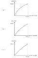
ここで、非直線性が向上する点についてを、図25のグラフを用いて簡単に説明する。図25(a)は、作用電極と参照電極との間にインピーダンス低減回路を非接続状態とした際の電極間電圧を縦軸、残留塩素の酸化還元反応を及ぼす濃度を横軸とし、測定したときの結果を示す。図25(b)、(c)は、作用電極と参照電極との間にインピーダンス低減回路((b)の場合と(c)の場合とでは負荷定数が異なる)を接続状態とした際の電極間電圧を縦軸、残留塩素の酸化還元反応を及ぼす濃度を横軸とし、測定したときの結果を示す。これら図に示されるように、非直線性は、作用電極と参照電極との間にインピーダンス低減回路が接続状態となり、インピーダンス低減回路の負荷定数(抵抗値)の大きさに従って変わることから向上する。 Here, the point of improving the non-linearity will be briefly described with reference to the graph of FIG. FIG. 25 (a) shows the measurement with the interelectrode voltage when the impedance reduction circuit is not connected between the working electrode and the reference electrode as the vertical axis and the concentration causing the redox reaction of residual chlorine as the horizontal axis. Show the results. FIGS. 25B and 25C show electrodes when the impedance reduction circuit (the load constant is different between (b) and (c)) is connected between the working electrode and the reference electrode. The measurement results are shown with the inter-axis voltage as the vertical axis and the concentration causing the redox reaction of residual chlorine as the horizontal axis. As shown in these figures, the non-linearity is improved because the impedance reduction circuit is connected between the working electrode and the reference electrode and changes according to the load constant (resistance value) of the impedance reduction circuit.
また、繰り返し性が向上する点についてを、図26のグラフを用いて簡単に説明する。図26(a)は、作用電極と参照電極との間にインピーダンス低減回路を非接続状態とした際の電極間電圧を縦軸、残留塩素の酸化還元反応を及ぼす濃度を横軸とし、複数回繰り返して測定したときの結果を示す。図26(b)、(c)は、作用電極と参照電極との間にインピーダンス低減回路((b)の場合と(c)の場合とでは負荷定数が異なる)を接続状態とした際の電極間電圧を縦軸、残留塩素の酸化還元反応を及ぼす濃度を横軸とし、複数回繰り返して測定したときの結果を示す。これら図に示されるように、繰り返し性は、作用電極と参照電極との間にインピーダンス低減回路が接続状態となり、インピーダンス低減回路の負荷定数(抵抗値)の大きさに従って変わることから向上する。 Further, the point that the repeatability is improved will be briefly described with reference to the graph of FIG. FIG. 26 (a) shows the voltage between the electrodes when the impedance reduction circuit is disconnected between the working electrode and the reference electrode on the vertical axis, and the horizontal axis indicates the concentration causing the redox reaction of residual chlorine. The results when repeated measurements are shown. FIGS. 26B and 26C show electrodes when the impedance reduction circuit (the load constant is different between (b) and (c)) is connected between the working electrode and the reference electrode. The results are shown when the measurement is repeated a plurality of times, with the inter-axis voltage as the vertical axis and the concentration causing the redox reaction of residual chlorine as the horizontal axis. As shown in these figures, the repeatability is improved because the impedance reduction circuit is connected between the working electrode and the reference electrode and changes according to the load constant (resistance value) of the impedance reduction circuit.
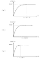
更に、測定時間が短縮する点についてを、図27のグラフを用いて簡単に説明する。図27(a)は、作用電極と参照電極との間にインピーダンス低減回路を非接続状態とした際の電極間電圧を縦軸、測定時間を横軸とし、測定したときの結果を示す。図27(b)、(c)は、作用電極と参照電極との間にインピーダンス低減回路((b)の場合と(c)の場合とでは負荷定数が異なる)を接続状態とした際の電極間電圧を縦軸、測定時間を横軸とし、測定したときの結果を示す。これら図に示されるように、測定時間は、作用電極と参照電極との間にインピーダンス低減回路が接続状態となり、インピーダンス低減回路の負荷定数(抵抗値)の大きさに従って変わることから短縮する。 Further, the point that the measurement time is shortened will be briefly described with reference to the graph of FIG. FIG. 27A shows the measurement results when the interelectrode voltage when the impedance reduction circuit is not connected between the working electrode and the reference electrode is taken as the vertical axis and the measurement time is taken as the horizontal axis. FIGS. 27B and 27C show electrodes when the impedance reduction circuit (the load constant is different between (b) and (c)) is connected between the working electrode and the reference electrode. The measurement results are shown with the voltage on the vertical axis and the measurement time on the horizontal axis. As shown in these figures, the measurement time is shortened because the impedance reduction circuit is connected between the working electrode and the reference electrode and changes according to the load constant (resistance value) of the impedance reduction circuit.
なお、後述する実施例1において、このように構成した酸化還元電位計についての具体的な説明をする。 In Example 1, which will be described later, the oxidation-reduction potentiometer configured as described above will be specifically described.
また、本発明の酸化還元電位計は、液の導電率を測定する導電率測定手段、及びこの導電率測定手段による導電率の測定と上述の電極間電圧測定手段による電極間電圧の測定とを切替える導電率測定切替手段を更に備え、上述の対比係数記憶部が、この導電率測定切替手段による電極間電圧の測定と導電率の測定との切替えに基づいて上述の対比係数演算部により演算した導電率の異なる各液に対する各対比係数を記憶し、上述の酸化還元電位演算部が、上述の低減回路切替手段により上述のインピーダンス低減回路を接続状態へと切替えた際に上述の電極間電圧測定手段により測定した接続状態における各電極間電圧と上述の対比係数記憶部に記憶した導電率の異なる各液に対する各対比係数のうちから上述の導電率測定手段により測定された液の導電率に対応する対比係数とに基づいて酸化還元電位を演算するといったものとしてもよい。 The oxidation-reduction potentiometer of the present invention comprises a conductivity measuring means for measuring the conductivity of a liquid, and the measurement of the conductivity by the conductivity measuring means and the measurement of the voltage between the electrodes by the above-mentioned voltage measuring means between the electrodes. Conductivity measurement switching means for switching is further provided, and the above-described contrast coefficient storage unit is operated by the above-described contrast coefficient calculation unit based on the switching between the measurement of the voltage between the electrodes and the measurement of the conductivity by the conductivity measurement switching means. Each contrast coefficient for each liquid having different conductivity is stored, and the above-described interelectrode voltage measurement is performed when the above-described oxidation-reduction potential calculation unit switches the above-described impedance reduction circuit to the connected state by the above-described reduction circuit switching unit. Measured by the above-mentioned conductivity measuring means from among the respective inter-electrode voltages in the connection state measured by the means and the respective contrast coefficients for the liquids having different conductivities stored in the above-mentioned contrast coefficient storage unit. Or as such calculates the oxidation-reduction potential based was on the comparison coefficient corresponding to the conductivity of the liquid.
このように構成した酸化還元電位計は、導電率が異なる複数の基準液についての導電率を導電率測定手段で測定し、導電率が異なる複数の基準液の各々についての対比係数を対比係数記憶部に記憶しておき、その後、被験液についての導電率を導電率測定手段により測定し、その被験液の導電率に応じた対比係数記憶部に記憶している対比係数を用いて酸化還元電位を酸化還元電位演算部により演算することができる。これによると、被験液の導電率に応じた酸化還元電位を得ることができる。したがって、本発明の酸化還元電位計は、より正確であるといった利点を有するものとなる。 The oxidation-reduction potentiometer configured in this way measures the conductivity of a plurality of reference solutions having different conductivities by means of conductivity measuring means, and stores the contrast coefficient for each of the plurality of reference solutions having different conductivities. And then the conductivity of the test solution is measured by the conductivity measuring means, and the redox potential is measured using the comparison coefficient stored in the comparison coefficient storage unit according to the conductivity of the test solution. Can be calculated by the oxidation-reduction potential calculation unit. According to this, the oxidation-reduction potential according to the electrical conductivity of the test solution can be obtained. Therefore, the oxidation-reduction potentiometer of the present invention has the advantage of being more accurate.
ここで、正確となる点についてを、図29のグラフを用いて簡単に説明する。図29は、電極間電圧を縦軸、インピーダンス低減回路の負荷定数(抵抗値)を横軸とし、測定したときの結果を示す。この図に示されるように、液の導電率により電極間電圧のばらつきが異なるが、このばらつきは、作用電極と参照電極との間にインピーダンス低減回路が接続状態となり、インピーダンス低減回路の負荷定数(抵抗値)の大きさに従って変わることから正確なものとなる。 Here, the point which becomes accurate is demonstrated easily using the graph of FIG. FIG. 29 shows the measurement results with the interelectrode voltage as the vertical axis and the load constant (resistance value) of the impedance reduction circuit as the horizontal axis. As shown in this figure, the variation in the voltage between the electrodes varies depending on the conductivity of the liquid. This variation is caused by the impedance reduction circuit being connected between the working electrode and the reference electrode, and the load constant ( It becomes accurate because it changes according to the magnitude of the resistance value.
なお、後述する実施例4において、このように構成した酸化還元電位計についての具体的な説明をする。 In Example 4 to be described later, the oxidation-reduction potentiometer configured as described above will be specifically described.
また、本発明の酸化還元電位計は、上述の酸化還元電位測定手段により酸化還元電位を測定する段階前に、上述の作用電極と上述の参照電極とが液に浸かっていることを測定する水没測定手段を更に備え、上述の低減回路切替手段が、この水没測定手段による測定の間、上述のインピーダンス低減回路を非接続状態へと切替えているといったものとしてもよい。 Further, the oxidation-reduction potentiometer of the present invention is a submersion that measures whether the working electrode and the reference electrode are immersed in a liquid before the step of measuring the oxidation-reduction potential by the oxidation-reduction potential measuring means. A measurement means may be further provided, and the above-described reduction circuit switching means may switch the above-described impedance reduction circuit to a non-connected state during measurement by the submergence measurement means.
このように構成した酸化還元電位計は、上述の酸化還元電位測定手段により酸化還元電位を測定する段階前に、作用電極と参照電極とが液に浸かっていることを水没測定手段により測定し、液に浸かっていることを測定している間は、上述のインピーダンス低減回路を非接続状態へと切替えていることができる。これによると、酸化還元電位を測定する段階前に、作用電極と参照電極とが液に浸かっている間はインピーダンス低減回路が非接続状態であるため、電極間に電流が流れず、電極は化学反応を起こさない。したがって、本発明の酸化還元電位計は、電極の寿命が高まるといった利点を有するものとなる。 The oxidation-reduction potentiometer configured in this way measures that the working electrode and the reference electrode are immersed in the liquid before the step of measuring the oxidation-reduction potential by the above-described oxidation-reduction potential measurement means, While measuring that it is immersed in a liquid, the above-mentioned impedance reduction circuit can be switched to a non-connection state. According to this, since the impedance reduction circuit is not connected while the working electrode and the reference electrode are immersed in the liquid before the step of measuring the redox potential, no current flows between the electrodes, Does not cause a reaction. Therefore, the oxidation-reduction potentiometer of the present invention has an advantage that the life of the electrode is increased.
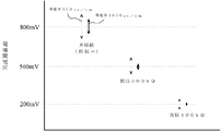
ここで、電極の寿命が高まる点についてを、図30のグラフを用いて簡単に説明する。図30は、電極間電圧を縦軸、水没経過時間を横軸とし、測定したときの結果を示す。この図に示されるように、作用電極と参照電極との間にインピーダンス低減回路が接続状態である場合には、水没経過時間に従って電極の反応による劣化が起こり電極間電圧が変化することから、酸化還元電位を測定する段階前について、非接続状態に常にすることで、電極の寿命が高まる。 Here, the point where the lifetime of the electrode is increased will be briefly described with reference to the graph of FIG. FIG. 30 shows the measurement results when the interelectrode voltage is the vertical axis and the submerged elapsed time is the horizontal axis. As shown in this figure, when the impedance reduction circuit is connected between the working electrode and the reference electrode, the deterioration due to the reaction of the electrode occurs according to the elapsed time of submergence, and the voltage between the electrodes changes. The life of the electrode is increased by always being in a disconnected state before the stage of measuring the reduction potential.
なお、後述する実施例5において、このように構成した酸化還元電位計についての具体的な説明をする。 In Example 5 to be described later, the oxidation-reduction potentiometer configured as described above will be specifically described.
また、本発明の酸化還元電位計は、上述の作用電極が、面積の異なる複数の作用電極から成り、これら面積の異なる複数の作用電極のうちのいずれかの作用電極に前記電極間電圧測定手段との接続を切替える作用電極切替手段を更に備え、上述のインピーダンス低減回路が、これら面積の異なる複数の各々の作用電極と上述の参照電極との間に生ずるインピーダンスを低減するものであり、上述の低減回路切替手段が、これら面積の異なる複数の各々の作用電極と上述の参照電極との間に上述のインピーダンス低減回路を非接続状態や接続状態に切替え、上述の電極間電圧測定手段が、この低減回路切替手段によりこのインピーダンス低減回路を非接続状態や接続状態に切替えた際におけるこれら面積の異なる複数の各々の作用電極により発生する各酸化還元反応の程度を表す電位と上述の参照電極により発生する基準となる電位との差である各電極間電圧を測定し、上述の対比係数演算部が、この電極間電圧測定手段により測定した非接続状態における各電極間電圧と接続状態における各電極間電圧とに基づいて各対比係数を演算し、上述の対比係数記憶部が、この対比係数演算部により演算した各対比係数を記憶し、上述の酸化還元電位演算部が、この低減回路切替手段によりこれら面積の異なる複数の各々の作用電極のうちの面積の小さなものから順にこのインピーダンス低減回路を接続状態へと切替えた際にこの電極間電圧測定手段により測定した接続状態における各電極間電圧とこの対比係数記憶部に記憶した各対比係数のうちの対応する対比係数とに基づいて酸化還元電位を演算するといったものとしてもよい。 In the oxidation-reduction potentiometer of the present invention, the above-mentioned working electrode is composed of a plurality of working electrodes having different areas, and the interelectrode voltage measuring means is connected to any one of the plurality of working electrodes having different areas. And the above-described impedance reduction circuit reduces impedance generated between each of the plurality of working electrodes having different areas and the above-described reference electrode. The reduction circuit switching means switches the impedance reduction circuit between the plurality of working electrodes having different areas and the reference electrode to a non-connected state or a connected state, and the inter-electrode voltage measuring means When the impedance reduction circuit is switched to a non-connected state or a connected state by the reduction circuit switching means, it is generated by each of the plurality of working electrodes having different areas. Each inter-electrode voltage, which is the difference between the potential representing the degree of each oxidation-reduction reaction and the reference potential generated by the above-mentioned reference electrode, is measured. Each contrast coefficient is calculated based on the measured inter-electrode voltage in the disconnected state and each inter-electrode voltage in the connected state, and the above-described contrast coefficient storage unit stores each contrast coefficient calculated by the contrast coefficient calculation unit. When the above-described oxidation-reduction potential calculation unit switches the impedance reduction circuit to the connected state in order from the smallest one of the plurality of working electrodes having different areas by the reduction circuit switching unit, Based on each inter-electrode voltage in the connection state measured by the inter-electrode voltage measuring means and the corresponding contrast coefficient stored in the contrast coefficient storage unit, redox Position may be things like calculates a.
このように構成した酸化還元電位計は、各々の作用電極と参照電極とを基準液に浸け、インピーダンス低減回路が各々の作用電極と参照電極との間に非接続状態の際における各電極間電圧と接続状態の際における各電極間電圧とを電極間電圧測定手段により測定し、これら測定した各電極間電圧に基づいて各対比係数を対比係数演算部により演算し、対比係数記憶部に記憶しておき、その後、各々の作用電極と参照電極とを被験液に浸け、インピーダンス低減回路が各々の作用電極と参照電極との間に、面積の小さな作用電極から順に接続状態した際における各電極間電圧とを電極間電圧測定手段により測定し、この測定した接続状態における各電極間電圧と対比係数記憶部に記憶した各対比係数とに基づいて酸化還元電位を酸化還元電位演算部により演算することができる。これによると、面積の大きな作用電極面積よりも反応スピードの速い小さな作用電極から順に測定する。したがって、本発明の酸化還元電位計は、測定時間が更に短縮するといった利点を有するものとなる。 The oxidation-reduction potentiometer configured in this way immerses each working electrode and reference electrode in a standard solution, and each inter-electrode voltage when the impedance reduction circuit is not connected between each working electrode and reference electrode. The inter-electrode voltage in the connected state is measured by the inter-electrode voltage measuring means, and the respective comparison coefficients are calculated by the comparison coefficient calculation unit based on the measured inter-electrode voltages, and stored in the comparison coefficient storage unit. After that, each working electrode and reference electrode are immersed in the test solution, and the impedance reduction circuit is connected between each working electrode and the reference electrode in order from the working electrode having the smallest area. The voltage is measured by the interelectrode voltage measuring means, and the redox potential is calculated based on the measured interelectrode voltage and the respective contrast coefficients stored in the contrast coefficient storage unit. It can be calculated by parts. According to this, measurement is performed in order from a small working electrode having a faster reaction speed than a working electrode area having a larger area. Therefore, the oxidation-reduction potentiometer of the present invention has an advantage that the measurement time is further shortened.
ここで、測定時間が短縮する点についてを、図31のグラフを用いて簡単に説明する。図31は、電極間電圧を縦軸、反応時間を横軸とし、測定したときの結果を示す。この図に示されるように、面積の小さい電極の方が面積の大きい電極の方よりも、ほぼ一定となるまでの反応時間が速いため、測定の一部を面積の小さい電極の方で測定することにより、測定時間が短縮する。 Here, the point that the measurement time is shortened will be briefly described with reference to the graph of FIG. FIG. 31 shows the measurement results with the interelectrode voltage as the vertical axis and the reaction time as the horizontal axis. As shown in this figure, since the reaction time until the electrode with a small area becomes almost constant is faster with the electrode with a small area, a part of the measurement is measured with the electrode with a small area. This shortens the measurement time.
なお、後述する実施例6及び実施例7において、このように構成した酸化還元電位計についての具体的な説明をする。 In addition, in Example 6 and Example 7 to be described later, the oxidation-reduction potentiometer configured as described above will be specifically described.
また、本発明の酸化還元電位計は、上述のインピーダンス低減回路が、上述の作用電極と上述の参照電極との間に生ずるインピーダンスを段階的に低減するものであり、上述の低減回路切替手段が、上述のインピーダンス低減回路を接続状態へと段階的に切替え、上述の電極間電圧測定手段が、このインピーダンス低減回路を接続状態へと段階的に切替えた際における各段階の電極間電圧を測定し、上述の対比係数演算部が、この電極間電圧測定手段により測定した接続状態における各段階の電極間電圧に基づいて各段階の対比係数を演算し、上述の対比係数記憶部が、この対比係数演算部により演算した各段階の対比係数を記憶し、上述の酸化還元電位演算部が、この低減回路切替手段によりこのインピーダンス低減回路を接続状態へと各段階のうちの一段階に切替えた際にこの電極間電圧測定手段により測定した接続状態における電極間電圧と、この対比係数記憶部に記憶した各段階の対比係数のうちの対応する段階の対比係数とに基づいて酸化還元電位値を演算するといったものとしてもよい。 In the oxidation-reduction potentiometer of the present invention, the impedance reduction circuit described above reduces the impedance generated between the working electrode and the reference electrode in a stepwise manner. The above-described impedance reduction circuit is switched to the connected state step by step, and the above-mentioned interelectrode voltage measuring means measures the inter-electrode voltage at each stage when this impedance reduction circuit is switched to the connected state step by step. The above-described contrast coefficient calculation unit calculates the contrast coefficient at each stage based on the inter-electrode voltage at each stage in the connection state measured by the inter-electrode voltage measuring means, and the above-described contrast coefficient storage unit stores the contrast coefficient. The comparison coefficient of each stage calculated by the calculation unit is stored, and the above-described oxidation-reduction potential calculation unit sets the impedance reduction circuit to the connected state by the reduction circuit switching unit. The inter-electrode voltage in the connection state measured by the inter-electrode voltage measuring means when switching to one of the floors, and the contrast coefficient of the corresponding stage among the contrast coefficients of each stage stored in the contrast coefficient storage unit The oxidation-reduction potential value may be calculated based on the above.
このように構成した酸化還元電位計は、作用電極と参照電極とを基準液に浸け、段階的に低減するインピーダンス低減回路が作用電極と参照電極との間に非接続状態の際における各段階の電極間電圧と接続状態の際における各段階の電極間電圧とを電極間電圧測定手段により測定し、これら測定した各段階の電極間電圧に基づいて各段階の対比係数を対比係数演算部により演算し、対比係数記憶部に記憶しておき、その後、作用電極と参照電極とを被験液に浸け、段階的に低減するインピーダンス低減回路が作用電極と参照電極との間に接続状態の際における各段階の電極間電圧を電極間電圧測定手段により測定し、この測定した接続状態における各段階の電極間電圧と対比係数記憶部に記憶している各段階の対比係数のうちの対応する段階の対比係数とに基づいて酸化還元電位を酸化還元電位演算部により演算することができる。これによると、インピーダンス低減回路の段階的な低減に応じて酸化還元反応を及ぼす濃度の範囲も段階的に広がる。したがって、本発明の酸化還元電位計は、測定範囲が広いといった利点を有するものとなる。 The oxidation-reduction potentiometer configured in this manner is soaked in the reference solution of the working electrode and the reference electrode, and the impedance reduction circuit that reduces in stages is not connected between the working electrode and the reference electrode. The inter-electrode voltage and the inter-electrode voltage at each stage in the connected state are measured by the inter-electrode voltage measuring means, and the contrast coefficient at each stage is calculated by the contrast coefficient calculating unit based on the measured inter-electrode voltage. The impedance reduction circuit that stores in the contrast coefficient storage unit and then immerses the working electrode and the reference electrode in the test solution and reduces them stepwise is connected between the working electrode and the reference electrode. The inter-electrode voltage of the stage is measured by the inter-electrode voltage measuring means, and the corresponding stage of the inter-electrode voltage of each stage in the measured connection state and the contrast coefficient of each stage stored in the contrast coefficient storage unit The redox potential can be calculated by a redox potential computing unit on the basis of the comparison coefficient. According to this, the range of the concentration that causes the oxidation-reduction reaction is gradually expanded in accordance with the gradual reduction of the impedance reduction circuit. Therefore, the oxidation-reduction potentiometer of the present invention has an advantage that the measurement range is wide.
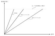
ここで、測定範囲が広がる点について、図28のグラフを用いて簡単に説明する。図28は、電極間電圧を縦軸、液の酸化還元反応を及ぼす濃度を横軸とし、測定した結果を示す。この図に示されるように、A/D変換最大電圧に対する液の酸化還元反応を及ぼす濃度が作用電極と参照電極との間に接続するインピーダンス低減回路の負荷定数(抵抗値)の大きさに従って広がるため、測定範囲が広くなる。 Here, the point where the measurement range is widened will be briefly described with reference to the graph of FIG. FIG. 28 shows the measurement results with the interelectrode voltage as the vertical axis and the concentration causing the redox reaction of the liquid as the horizontal axis. As shown in this figure, the concentration causing the redox reaction of the liquid with respect to the A / D conversion maximum voltage spreads according to the load constant (resistance value) of the impedance reduction circuit connected between the working electrode and the reference electrode. Therefore, the measurement range is widened.
なお、後述する実施例2及び実施例3において、このように構成した酸化還元電位計についての具体的な説明をする。 In addition, in Example 2 and Example 3 to be described later, the oxidation-reduction potentiometer configured in this way will be specifically described.
以下、上述した各種の実施形態について、図面を用いて詳細に説明する。 Hereinafter, various embodiments described above will be described in detail with reference to the drawings.
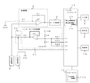
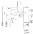
まず、図1に示す外観図、図2に示すブロック図を用いて、本発明に係わる酸化還元電位計の具体的な構成について説明する。 First, a specific configuration of the oxidation-reduction potentiometer according to the present invention will be described with reference to an external view shown in FIG. 1 and a block diagram shown in FIG.
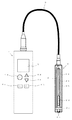
実施例1としての酸化還元電位計は、正面に入力部4及び表示器5を有する本体1と、作用電極6兼参照電極7であるセンサー2と、本体1とセンサー2とを接続するケーブル3とを外見上に備え、増幅回路8、A/D変換器9、インピーダンス低減回路10、低減回路切替スイッチ11、EEPROM12及びマイクロコンピュータ13を配設する電子基板と、電源部14とを本体1の内部に備えることにより、全体を大略構成する。
The oxidation-reduction potentiometer as Example 1 includes a
入力部4は、ONキー4a、スタートキー4b、モードキー4c、+キー4d及び−キー4eから成り、電力供給・測定開始・切替等をするための入力をする。ONキー4aは、電源部14から電気系統各部に電力の供給を開始するためものである。スタートキー4bは、測定を開始するためのである。モードキー4cは、調整モードと測定モードとを切替えるためのものである。+キー4d、−キー4eは、表示器5に表示する項目や数値等を選択をするためのものである。
The
表示器5は、入力状況・測定結果・各種モード・電池残量等を表示する。
The
センサー2は、内側ガラス管(図1において透明にて示す。)2aの外側に間隙を設けて覆う外側ガラス管(図1において透明にて示す。)2bを形成し、内側ガラス管2aの外側から外側ガラス管2bの外側にかけて白金(Pt)2cを配設し、内側ガラス管2aの内部に、銀(Ag)に塩化銀(AgCl)を被覆した内部電極2dを設けるとともに液状又はゲル状の塩化ナトリウム(NaCl)又は塩化カリウム(KCl)を充填し、内側ガラス管2aの内部から内側ガラス管2aかつ外側ガラス管2bの外側にかけて液絡部2eを配設し、白金(Pt)2cと内部電極2dとには電子基板につながる導線2f、2gが接続する。
The
なお、白金(Pt)2c部分が作用電極6に該当し、内側ガラス管2a、内部電極2d、塩化ナトリウム(NaCl)又は塩化カリウム(KCl)、液絡部2eにかけての部分が参照電極7に該当する。
The platinum (Pt) 2c portion corresponds to the working
電源部14は、電気系統各部に電力を供給する。
The
増幅回路8は、測定した作用電極6により発生する酸化還元反応の程度を表す電位と参照電極7により発生する基準となる電位との差である電極間電圧(アナログ信号)を増幅する。A/D変換器9は、この増幅された電極間電圧をデジタル信号に変換する。
The amplifying
インピーダンス低減回路10は、作用電極6と参照電極7との間に低減回路切替スイッチ11により非接続状態及び接続状態となり得るように配設する抵抗(R11)から成り、液に浸けた際における作用電極6と参照電極7との間に生ずるインピーダンスを低減する。
The
低減回路切替スイッチ11は、マイクロコンピュータ13からの制御信号に基づいてインピーダンス低減回路10を非接続状態及び接続状態へと切替える。
The reduction
EEPROM12は、対比係数記憶部12aを兼有し、各種データを記憶する。対比係数記憶部12aは、後述する対比係数演算部13aにより演算した対比係数を記憶する。
The EEPROM 12 also has a contrast
マイクロコンピュータ13は、対比係数演算部13aと酸化還元電位演算部13bとを兼有し、各種データ等について演算し、また、低減回路切替スイッチ11の切替え、各種データの判定等について制御する。
The
対比係数演算部13aは、インピーダンス低減回路10が非接続状態におけるA/D変換器9からの電極間電圧(基準液電圧)と、インピーダンス低減回路10が接続状態におけるA/D変換器9からの電極間電圧(基準液電圧)とに基づいて対比係数を演算する。より具体的には、次の演算式(1)に示すように、インピーダンス低減回路10が非接続状態におけるA/D変換器9からの電極間電圧Vr0をインピーダンス低減回路10が接続状態におけるA/D変換器9からの電極間電圧Vr1で除すことによって、対比係数k1を演算する。
k1=Vr0/Vr1 ・・・ (1)
The contrast coefficient calculation unit 13a is configured such that the interelectrode voltage (reference liquid voltage) from the A /
k1 = Vr0 / Vr1 (1)
酸化還元電位演算部13bは、マイクロコンピュータ13からの制御信号に基づいてインピーダンス低減回路10を接続状態へと切替えた際に、インピーダンス低減回路10が接続状態におけるA/D変換器9からの電極間電圧と、対比係数記憶部12aに記憶した対比係数とに基づいて酸化還元電位を演算する。より具体的には、次の演算式(2)に示すように、インピーダンス低減回路10が接続状態におけるA/D変換器9からの電極間電圧Vs1に対比係数記憶部12aに記憶した対比係数k1を乗じることによって、インピーダンス低減回路10が非接続状態におけるA/D変換器9からの電極間電圧(被験液電圧)、すなわち、酸化還元電位Vs0を演算する。
Vs0=k1×Vs1 ・・・ (2)
When the
Vs0 = k1 × Vs1 (2)
なお、低減回路切替スイッチ11及びマイクロコンピュータ13にて低減回路切替手段を構成する。また、増幅回路8、A/D変換器9及びマイクロコンピュータ13にて電極間電圧測定手段を構成する。また、低減回路切替手段、電極間電圧測定手段、対比係数演算部13a、対比係数記憶部12a及び酸化還元電位演算部13bにて酸化還元電位測定手段を構成する。
The reduction
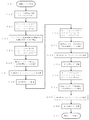
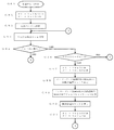
次に、図3に示す調整モードにおけるフローチャート、図4に示す通常モードにおけるフローチャートを用いて、本発明に係わる酸化還元電位計の具体的な操作及び動作について説明する。 Next, specific operations and operations of the oxidation-reduction potentiometer according to the present invention will be described using the flowchart in the adjustment mode shown in FIG. 3 and the flowchart in the normal mode shown in FIG.
まず、調整モードにおける具体的な操作及び動作について詳述する。 First, specific operations and operations in the adjustment mode will be described in detail.
ONキー4aが押されると電源部14から電気系統各部に電力を供給し、図4に示すフローチャートに沿って後に説明する通常モードに入る(ステップG1)。そして、この後、モードキー4cが押されると図3に示すフローチャートに沿った調整モードに入る(ステップC1)。
When the ON key 4a is pressed, power is supplied from the
続いて、センサー2が基準液に浸けられ、スタートキー4bが押されると(ステップC2)、マイクロコンピュータ13のポートP1からのOFF制御信号に基づいて低減回路切替スイッチ(Sw1)11がオフし、インピーダンス低減回路(R11)10が非接続状態となる(ステップC3)。
Subsequently, when the
続いて、この時の作用電極6と参照電極7との間に発生する電極間電圧(アナログ信号)を増幅回路8により増幅し、A/D変換器9によりデジタル信号に変換し、マイクロコンピュータ13により非接続時の電極間電圧(基準液電圧)Vr0として演算する(ステップC4)。
Subsequently, the interelectrode voltage (analog signal) generated between the working
続いて、マイクロコンピュータ13のポートP1からのON制御信号に基づいて低減回路切替スイッチ(Sw1)11がオンし、インピーダンス低減回路(R11)10が接続状態となる(ステップC5)。
Subsequently, the reduction circuit selector switch (Sw1) 11 is turned on based on the ON control signal from the port P1 of the
続いて、この時の作用電極6と参照電極7との間に発生する電極間電圧(アナログ信号)を増幅回路8により増幅し、A/D変換器9によりデジタル信号に変換し、マイクロコンピュータ13により接続時の電極間電圧(基準液電圧)Vr1として演算する(ステップC6)。
Subsequently, the interelectrode voltage (analog signal) generated between the working
続いて、対比係数演算部13aにおいて、上述した演算式(1)に示すように、非接続の電極間電圧(基準液電圧)Vr0を、接続時の電極間電圧(基準液電圧)Vr1で除すことによって、対比係数k1を演算し(ステップC7)、対比係数記憶部12aにおいて、この演算した対比係数k1を記憶すると(ステップC8)、この調整モードを抜ける(ステップC9)。
Subsequently, in the contrast coefficient calculation unit 13a, as shown in the above-described calculation formula (1), the non-connected interelectrode voltage (reference liquid voltage) Vr0 is divided by the interelectrode voltage (reference liquid voltage) Vr1 at the time of connection. Thus, the contrast coefficient k1 is calculated (step C7). When the calculated contrast coefficient k1 is stored in the contrast
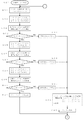
次に、通常モードにおける具体的な操作及び動作について詳述する。 Next, specific operations and operations in the normal mode will be described in detail.
ONキー4aが押された直後、又は調整モードを抜けた後は、図4に示すフローチャートに沿った通常モードと入る(ステップG1)。 Immediately after the ON key 4a is pressed or after exiting the adjustment mode, the normal mode according to the flowchart shown in FIG. 4 is entered (step G1).
続いて、センサー2が被験液に浸けられ、スタートキー4bが押されると(ステップG2)、マイクロコンピュータ13のポートP1からのON制御信号に基づいて低減回路切替スイッチ(Sw1)11がオンし、インピーダンス低減回路(R11)10が接続状態となる(ステップG3)。
Subsequently, when the
続いて、この時の作用電極6と参照電極7との間に発生する電極間電圧(アナログ信号)を増幅回路8により増幅し、A/D変換器9によりデジタル信号に変換し、マイクロコンピュータ13により接続時の電極間電圧(被験液電圧)Vs1として演算する(ステップG4)。
Subsequently, the interelectrode voltage (analog signal) generated between the working
続いて、酸化還元電位演算部13bにおいて、上述した演算式(2)に示すように、接続時の電極間電圧(被験液電圧)Vs1に、対比係数記憶部12aに記憶している対比係数k1を乗じることによって、非接続時の電極間電圧(被験液電圧)、すなわち、酸化還元電位Vs0を演算し(ステップG5)、この結果を表示器5に表示する(ステップG6)。
Subsequently, in the oxidation-reduction
なお、以降、ステップG2に戻り、処理を繰り返すことが可能となる。 Thereafter, the process can be repeated by returning to step G2.
まず、図1に示す外観図、図5に示すブロック図を用いて、本発明に係わる酸化還元電位計の具体的な構成について説明する。 First, the specific configuration of the oxidation-reduction potentiometer according to the present invention will be described with reference to the external view shown in FIG. 1 and the block diagram shown in FIG.
実施例2としての酸化還元電位計は、実施例1として説明した酸化還元電位計とほぼ同様に、全体を大略構成する。以下、実施例1として説明した酸化還元電位計とは異なる構成各部についてのみ詳述する。 The oxidation-reduction potentiometer as Example 2 is generally configured in the same manner as the oxidation-reduction potentiometer described as Example 1. Hereinafter, only the components that are different from the oxidation-reduction potentiometer described as Example 1 will be described in detail.
インピーダンス低減回路21は、作用電極6と参照電極7との間に低減回路切替スイッチ22により非接続状態及び接続状態となり得るように配設する抵抗値の異なる複数の抵抗R11、R12、R13から成り、液に浸けた際における作用電極6と参照電極7との間に生ずるインピーダンスを多段階的に低減する。
The
低減回路切替スイッチ22は、マイクロコンピュータ13からの制御信号に基づいて、インピーダンス低減回路21を多段階的に非接続状態及び接続状態へと切替える。
The reduction
対比係数演算部13aは、インピーダンス低減回路21のうちのすべての抵抗が非接続状態におけるA/D変換器9からの電極間電圧(基準液電圧)と、インピーダンス低減回路21のうちの各段階の抵抗が接続状態におけるA/D変換器9からの電極間電圧(基準液電圧)とに基づいて各対比係数を演算する。より具体的には、次の演算式(3)に示すように、インピーダンス低減回路21のうちのすべての抵抗が非接続状態におけるA/D変換器9からの電極間電圧Vr0を、インピーダンス低減回路21のうちのいずれかの段階の抵抗が接続状態におけるA/D変換器9からの電極間電圧VrN(なお、Nは段階値を示す。)で除すことによって、いずれかの段階の対比係数kN(なお、Nは段階値を示す。)を演算する、といったことをすべての段階について演算する。
kN=Vr0/VrN ・・・ (3)
The contrast coefficient calculation unit 13a is configured such that the inter-electrode voltage (reference liquid voltage) from the A /
kN = Vr0 / VrN (3)
酸化還元電位演算部13bは、マイクロコンピュータからの制御信号に基づいてインピーダンス低減回路21の各段階の接続状態へと切替えた際に、インピーダンス低減回路21が各段階の接続状態におけるA/D変換器9からの電極間電圧と、対比係数記憶部12aに記憶した各段階の対比係数とに基づいて酸化還元電位を演算する。より具体的には、次の演算式(4)に示すように、インピーダンス低減回路21のうちのいずれかの段階のものが接続状態におけるA/D変換器9からの電極間電圧VsNに、対比係数記憶部12aに記憶した対応する段階の対比係数kNを乗じることによって、インピーダンス低減回路21が非接続状態におけるA/D変換器9からの電極間電圧(被験液電圧)、すなわち、酸化還元電位Vs0を演算する。
Vs0=kN×VsN ・・・ (4)
When the oxidation reduction
Vs0 = kN × VsN (4)
次に、図6に示す調整モードにおけるフローチャート、図7に示す通常モードにおけるフローチャートを用いて、本発明に係わる酸化還元電位計の具体的な操作及び動作について説明する。 Next, specific operations and operations of the oxidation-reduction potentiometer according to the present invention will be described using the flowchart in the adjustment mode shown in FIG. 6 and the flowchart in the normal mode shown in FIG.
まず、調整モードにおける具体的な操作及び動作について詳述する。 First, specific operations and operations in the adjustment mode will be described in detail.
ONキー4aが押されると電源部14から電気系統各部に電力を供給し、図7に示すフローチャートに沿って後に説明する通常モードに入る(ステップG21)。そして、この後、モードキー4cが押されると図6に示すフローチャートに沿った調整モードに入る(ステップC21)。
When the ON key 4a is pressed, power is supplied from the
続いて、センサー2が基準液に浸けられ、スタートキー4bが押されると(ステップC22)、マイクロコンピュータ13のポートP1、P2、P3からのOFF制御信号に基づいて低減回路切替スイッチ(Sw1、Sw2、Sw3)22がオフし、インピーダンス低減回路(R11、R12、R13)21が非接続状態となる(ステップC23)。
Subsequently, when the
続いて、この時の作用電極6と参照電極7との間に発生する電極間電圧(アナログ信号)を増幅回路8により増幅し、A/D変換器9によりデジタル信号に変換し、マイクロコンピュータ13により非接続時の電極間電圧(基準液電圧)Vr0として演算する(ステップC24)。
Subsequently, the interelectrode voltage (analog signal) generated between the working
続いて、マイクロコンピュータ13のポートP1からのON制御信号に基づいて低減回路切替スイッチ22のうちのSw1がオンし、インピーダンス低減回路21のうちの一段階目の抵抗R11が接続状態となる(ステップC25)。
Subsequently, Sw1 of the reduction
続いて、この時の作用電極6と参照電極7との間に発生する電極間電圧(アナログ信号)を増幅回路8により増幅し、A/D変換器9によりデジタル信号に変換し、マイクロコンピュータ13により一段階目の抵抗R11が接続時の電極間電圧(基準液電圧)Vr1として演算する(ステップC26)。
Subsequently, the interelectrode voltage (analog signal) generated between the working
続いて、対比係数演算部13bにおいて、上述した演算式(3)に示すように、すべてが非接続の電極間電圧(基準液電圧)Vr0を、一段階目の抵抗R11が接続時の電極間電圧(基準液電圧)Vr1で除すことによって、一段階目の対比係数k1を演算し(ステップC27)、対比係数記憶部12aにおいて、この演算した一段階目の対比係数k1を記憶する(ステップC28)。
Subsequently, in the contrast
続いて、マイクロコンピュータ13のポートP1からのOFF制御信号に基づいて低減回路切替スイッチ22のうちのSw1がオフし、マイクロコンピュータ13のポートP2からのON制御信号に基づいて低減回路切替スイッチ22のうちのSw2がオンし、インピーダンス低減回路21のうちの二段階目の抵抗R12が接続状態となる(ステップC29)。
Subsequently, Sw1 of the reduction
続いて、この時の作用電極6と参照電極7との間に発生する電極間電圧(アナログ信号)を増幅回路8により増幅し、A/D変換器9によりデジタル信号に変換し、マイクロコンピュータにより二段階目の抵抗R12が接続時の電極間電圧(基準液電圧)Vr2として演算する(ステップC30)。
Subsequently, the interelectrode voltage (analog signal) generated between the working
続いて、対比係数演算部13aにおいて、上述した演算式(3)に示すように、すべてが非接続の電極間電圧(基準液電圧)Vr0を、二段階目の抵抗R12が接続時の電極間電圧(基準液電圧)Vr2で除すことによって、二段階目の対比係数k2を演算し(ステップC31)、対比係数記憶部において、この演算した二段階目の対比係数k2を記憶する(ステップC32)。 Subsequently, in the contrast coefficient calculation unit 13a, as shown in the above-described calculation formula (3), all the non-connected inter-electrode voltages (reference liquid voltages) Vr0 and the second-stage resistor R12 are connected between the electrodes when connected. By dividing by the voltage (reference liquid voltage) Vr2, the second-stage contrast coefficient k2 is calculated (step C31), and the calculated second-stage contrast coefficient k2 is stored in the contrast coefficient storage unit (step C32). ).
続いて、マイクロコンピュータ13のポートP2からのOFF制御信号に基づいて低減回路切替スイッチ22のうちのSw2がオフし、マイクロコンピュータ13のポートP3からのON制御信号に基づいて低減回路切替スイッチ22のうちのSw3がオンし、インピーダンス低減回路21のうちの三段階目の抵抗R13が接続状態となる(ステップC33)。
Subsequently, Sw2 of the reduction
続いて、この時の作用電極6と参照電極7との間に発生する電極間電圧(アナログ信号)を増幅回路8により増幅し、A/D変換器9によりデジタル信号に変換し、マイクロコンピュータ13により三段階目の抵抗R13が接続時の電極間電圧(基準液電圧)Vr3として演算する(ステップC34)。
Subsequently, the interelectrode voltage (analog signal) generated between the working
続いて、対比係数演算部13aにおいて、上述した演算式(3)に示すように、すべてが非接続の電極間電圧(基準液電圧)Vr0を、三段階目の抵抗R13が接続時の電極間電圧(基準液電圧)Vr3で除すことによって、三段階目の対比係数k3を演算し(ステップC35)、対比係数記憶部12aにおいて、この演算した三段階目の対比係数k3を記憶すると(ステップC36)、この調整モードを抜ける(ステップC37)。
Subsequently, in the contrast coefficient calculation unit 13a, as shown in the above-described calculation formula (3), all the unconnected inter-electrode voltage (reference liquid voltage) Vr0 and the third-stage resistor R13 are connected between the electrodes when connected. By dividing by the voltage (reference liquid voltage) Vr3, the third-stage contrast coefficient k3 is calculated (step C35), and the calculated third-stage contrast coefficient k3 is stored in the contrast
次に、通常モードにおける具体的な操作及び動作について詳述する。 Next, specific operations and operations in the normal mode will be described in detail.
ONキー4aが押された直後、又は調整モードを抜けた後は、図7に示すフローチャートに沿った通常モードと入る(ステップG21)。 Immediately after the ON key 4a is pressed or after exiting the adjustment mode, the normal mode according to the flowchart shown in FIG. 7 is entered (step G21).
続いて、センサー2が被験液に浸けられ、スタートキー4bが押されると(ステップG22)、マイクロコンピュータ13のポートP1からのON制御信号に基づいて低減回路切替スイッチ22のうちのSw1がオンし、インピーダンス低減回路21のうちの一段階目の抵抗R11が接続状態となる(ステップG23)。
Subsequently, when the
続いて、この時の作用電極6参照電極7との間に発生する電極間電圧(アナログ信号)を増幅回路8により増幅し、A/D変換器9によりデジタル信号に変換し、マイクロコンピュータ13により一段階目の抵抗R11が接続時の電極間電圧(被験液電圧)Vs1として演算する(ステップG24)。
Subsequently, the interelectrode voltage (analog signal) generated between the working
続いて、この演算した一段階目の抵抗R11が接続時の電極間電圧(被験液電圧)Vs1が増幅回路8の増幅許容範囲をオーバーしているか否かをマイクロコンピュータ13により判定する(ステップG25)。
Subsequently, the
続いて、マイクロコンピュータ13において、この判定結果が増幅許容範囲をオーバーしていない場合には(ステップG25でNO)、対比係数記憶部12aに記憶した一段階目の対比係数k1を呼び出す(ステップG33)。
Subsequently, in the
一方、マイクロコンピュータ13において、この判定結果が増幅許容範囲をオーバーしている場合には(ステップG25でYES)、マイクロコンピュータ13のポートP1からのOFF制御信号に基づいて低減回路切替スイッチ22のうちのSw1がオフし、マイクロコンピュータ13のポートP2からのON制御信号に基づいて低減回路切替スイッチ22のうちのSw2がオンし、インピーダンス低減回路21のうちの二段階目の抵抗R12が接続状態となる(ステップC26)。
On the other hand, in the
続いて、この時の作用電極6と参照電極7との間に発生する電極間電圧(アナログ信号)を増幅回路8により増幅し、A/D変換器9によりデジタル信号に変換し、マイクロコンピュータ13により二段階目の抵抗R12が接続時の電極間電圧(被験液電圧)Vs2として演算する(ステップG27)。
Subsequently, the interelectrode voltage (analog signal) generated between the working
続いて、この演算した二段階目の抵抗R12が接続時の電極間電圧(被験液電圧)Vs2が増幅回路8の増幅許容範囲をオーバーしているか否かをマイクロコンピュータ13により判定する(ステップG28)。
Subsequently, the
続いて、マイクロコンピュータ13において、この判定結果が増幅許容範囲をオーバーしていない場合には(ステップG28でNO)、対比係数記憶部12aに記憶した二段階目の対比係数k2を呼び出す(ステップG34)。
Subsequently, in the
一方、マイクロコンピュータ13において、この判定結果が増幅許容範囲をオーバーしている場合には(ステップG28でYES)、マイクロコンピュータ13のポートP2からのOFF制御信号に基づいて低減回路切替スイッチ22のうちのSw2がオフし、マイクロコンピュータ13のポートP3からのON制御信号に基づいて低減回路切替スイッチ22のうちのSw3がオンし、インピーダンス低減回路のうちの三段階目の抵抗R13が接続状態となる(ステップC29)。
On the other hand, in the
続いて、この時の作用電極6と参照電極7との間に発生する電極間電圧(アナログ信号)を増幅回路8により増幅し、A/D変換器9によりデジタル信号に変換し、マイクロコンピュータ13により三段階目の抵抗R13が接続時の電極間電圧(被験液電圧)Vs3として演算する(ステップG30)。
Subsequently, the interelectrode voltage (analog signal) generated between the working
続いて、この演算した三段階目の抵抗R13が接続時の電極間電圧(被験液電圧)Vs3が増幅回路8の増幅許容範囲をオーバーしているか否かをマイクロコンピュータ13により判定する(ステップG31)。
Subsequently, the
続いて、マイクロコンピュータ13において、この判定結果が増幅許容範囲をオーバーしていない場合には(ステップG31でNO)、対比係数記憶部12aに記憶した三段階目の対比係数k3を呼び出す(ステップG35)。
Subsequently, in the
一方、マイクロコンピュータ13において、この判定結果が増幅許容範囲をオーバーしている場合には(ステップG31でYES)、増幅許容範囲外である旨を表すエラーメッセージを表示器5に表示する(ステップG32)。 On the other hand, if the determination result exceeds the allowable amplification range in the microcomputer 13 (YES in step G31), an error message indicating that the amplification is out of the allowable range is displayed on the display 5 (step G32). ).
続いて、酸化還元電位演算部13bにおいて、上述した演算式(4)に示すように、いずれかの段階のものが接続時の電極間電圧(被験液電圧)VsNに、対比係数記憶部12aに記憶した対応する段階の対比係数kNを乗じることによって、非接続時の電極間電圧(被験液電圧)、すなわち、酸化還元電位Vs0を演算し(ステップG36)、この結果を表示器5に表示する(ステップG37)。
Subsequently, in the oxidation-reduction
なお、以降、ステップG22に戻り、処理を繰り返すことが可能となる。 Thereafter, it is possible to return to step G22 and repeat the process.
まず、図1に示す外観図、図8に示すブロック図を用いて、本発明に係わる酸化還元電位計の具体的な構成について説明する。 First, the specific configuration of the oxidation-reduction potentiometer according to the present invention will be described with reference to the external view shown in FIG. 1 and the block diagram shown in FIG.
実施例3としての酸化還元電位計は、実施例2として説明した酸化還元電位計とほぼ同様に、全体を大略構成する。以下、実施例2として説明した酸化還元電位計とは異なる構成各部についてのみ詳述する。 The oxidation-reduction potentiometer as Example 3 is generally configured in the same manner as the oxidation-reduction potentiometer described as Example 2. Hereinafter, only the components that are different from the oxidation-reduction potentiometer described as the second embodiment will be described in detail.
インピーダンス低減回路31は、電圧を生成する電圧生成回路R6、R7と、この電圧生成回路R6、R7に接続するボルテージ・フォロワA2と、このボルテージ・フォロワA2と作用電極6との間に接続する出力抵抗R8とから成り、作用電極6と参照電極7との間に低減回路切替スイッチ(Sw4)32により非接続状態及び接続状態となり得るように配設し、液に浸けた際における作用電極6と参照電極7との間に生ずるインピーダンスを多段階的に低減する。
The impedance reduction circuit 31 includes voltage generation circuits R6 and R7 for generating a voltage, a voltage follower A2 connected to the voltage generation circuits R6 and R7, and an output connected between the voltage follower A2 and the working
低減回路切替スイッチ22は、マイクロコンピュータ13からの制御信号に基づいて、インピーダンス低減回路31を非接続状態及び接続状態へと切替える。
The reduction
次に、図9に示す調整モードにおけるフローチャート、図10に示す通常モードにおけるフローチャートを用いて、本発明に係わる酸化還元電位計の具体的な操作及び動作について説明する。 Next, specific operations and operations of the oxidation-reduction potentiometer according to the present invention will be described using the flowchart in the adjustment mode shown in FIG. 9 and the flowchart in the normal mode shown in FIG.
まず、調整モードにおける具体的な操作及び動作について詳述する。 First, specific operations and operations in the adjustment mode will be described in detail.
ONキー4aが押されると電源部14から電気系統各部に電力を供給し、図10に示すフローチャートに沿って後に説明する通常モードに入る(ステップG41)。そして、この後、モードキー4cが押されると図9に示すフローチャートに沿った調整モードに入る(ステップC41)。
When the ON key 4a is pressed, power is supplied from the
続いて、センサー2が基準液に浸けられ、スタートキー4bが押されると(ステップC42)、マイクロコンピュータ13のポートP1、P2、P3のすべてがオープンとなり、また、マイクロコンピュータ13のポートP4からのOFF制御信号に基づいて低減回路切替スイッチ(Sw4)32がオフし、インピーダンス低減回路31が非接続状態となる(ステップC43)。
Subsequently, when the
続いて、この時の作用電極6と参照電極7との間に発生する電極間電圧(アナログ信号)を増幅回路8により増幅し、A/D変換器9によりデジタル信号に変換し、マイクロコンピュータ13により非接続時の電極間電圧(基準液電圧)Vr0として演算する(ステップC44)。
Subsequently, the interelectrode voltage (analog signal) generated between the working
続いて、マイクロコンピュータ13のポートP1がLOWレベル制御信号となり、また、マイクロコンピュータ13のポートP4からのON制御信号に基づいて低減回路切替スイッチ(Sw4)22がオンし、インピーダンス低減回路31が一段階出力レベルで接続状態となる(ステップC45)。
Subsequently, the port P1 of the
続いて、この時の作用電極6と参照電極7との間に発生する電極間電圧(アナログ信号)を増幅回路8により増幅し、A/D変換器9によりデジタル信号に変換し、マイクロコンピュータ13により一段階出力レベルで接続時の電極間電圧(基準液電圧)Vr1として演算する(ステップC46)。
Subsequently, the interelectrode voltage (analog signal) generated between the working
続いて、対比係数演算部13aにおいて、上述した演算式(3)に示すように、すべてが非接続の電極間電圧(基準液電圧)Vr0を、一段階出力レベルで接続時の電極間電圧(基準液電圧)Vr1で除すことによって、一段階出力レベルの対比係数k1を演算し(ステップC47)、対比係数記憶部12aにおいて、この演算した一段階出力レベルでの対比係数k1を記憶する(ステップC48)。
Subsequently, in the contrast coefficient calculation unit 13a, as shown in the above-described calculation formula (3), the inter-electrode voltage (reference liquid voltage) Vr0, which is all unconnected, is set to the inter-electrode voltage at the time of connection at the one-step output level ( By dividing by the reference liquid voltage (Vr1), the contrast coefficient k1 of the one-stage output level is calculated (step C47), and the contrast coefficient k1 at the calculated one-stage output level is stored in the contrast
続いて、マイクロコンピュータ13のポートP1がオープンとなり、マイクロコンピュータ13のポートP2がLOWレベル制御信号となり、インピーダンス低減回路31が二段階出力レベルで接続状態となる(ステップC49)。
Subsequently, the port P1 of the
続いて、この時の作用電極6と参照電極7との間に発生する電極間電圧(アナログ信号)を増幅回路8により増幅し、A/D変換器9によりデジタル信号に変換し、マイクロコンピュータ13により二段階出力レベルで接続時の電極間電圧(基準液電圧)Vr2として演算する(ステップC50)。
Subsequently, the interelectrode voltage (analog signal) generated between the working
続いて、対比係数演算部13aにおいて、上述した演算式(3)に示すように、すべてが非接続の電極間電圧(基準液電圧)Vr0を、二段階出力レベルで接続時の電極間電圧(基準液電圧)Vr2で除すことによって、二段階出力レベルの対比係数k2を演算し(ステップC51)、対比係数記憶部12aにおいて、この演算した二段階出力レベルでの対比係数k2を記憶する(ステップC52)。
Subsequently, in the contrast coefficient calculation unit 13a, as shown in the above-described calculation formula (3), the inter-electrode voltage (reference liquid voltage) Vr0, which is all unconnected, is set to the inter-electrode voltage (the connection voltage at the two-stage output level ( By dividing by the reference liquid voltage (Vr2), the contrast coefficient k2 of the two-stage output level is calculated (step C51), and the contrast coefficient k2 at the calculated two-stage output level is stored in the contrast
続いて、マイクロコンピュータ13のポートP2がオープンとなり、マイクロコンピュータ13のポートP3がLOWレベル制御信号となり、インピーダンス低減回路31が三段階出力レベルで接続状態となる(ステップC53)。
Subsequently, the port P2 of the
続いて、この時の作用電極6と参照電極7との間に発生する電極間電圧(アナログ信号)を増幅回路8により増幅し、A/D変換器9によりデジタル信号に変換し、マイクロコンピュータ13により三段階出力レベルで接続時の電極間電圧(基準液電圧)Vr3として演算する(ステップC54)。
Subsequently, the interelectrode voltage (analog signal) generated between the working
続いて、対比係数演算部13bにおいて、上述した演算式(3)に示すように、すべてが非接続の電極間電圧(基準液電圧)Vr0を、三段階出力レベルで接続時の電極間電圧(基準液電圧)Vr3で除すことによって、三段階出力レベルの対比係数k3を演算し(ステップC55)、対比係数記憶部12aにおいて、この演算した三段階出力レベルでの対比係数k3を記憶すると(ステップC56)、この調整モードを抜ける(ステップC57)。
Subsequently, in the contrast
次に、通常モードにおける具体的な操作及び動作について詳述する。 Next, specific operations and operations in the normal mode will be described in detail.
ONキー4aが押された直後、又は調整モードを抜けた後は、図10に示すフローチャートに沿った通常モードと入る(ステップG41)。 Immediately after the ON key 4a is pressed or after exiting the adjustment mode, the normal mode according to the flowchart shown in FIG. 10 is entered (step G41).
続いて、センサー2が被験液に浸けられ、スタートキー4bが押されると(ステップG42)、マイクロコンピュータ13のポートP1がLOWレベル制御信号となり、また、マイクロコンピュータ13のポートP4からのON制御信号に基づいて低減回路切替スイッチ(Sw4)32がオンし、インピーダンス低減回路31が一段階出力レベルで接続状態となる(ステップG43)。
Subsequently, when the
続いて、この時の作用電極6と参照電極7との間に発生する電極間電圧(アナログ信号)を増幅回路8により増幅し、A/D変換器9によりデジタル信号に変換し、マイクロコンピュータ13により一段階出力レベルで接続時の電極間電圧(被験液電圧)Vs1として演算する(ステップG44)。
Subsequently, the interelectrode voltage (analog signal) generated between the working
続いて、この演算した一段階出力レベルで接続時の電極間電圧(被験液電圧)Vs1が増幅回路8の増幅許容範囲をオーバーしているか否かをマイクロコンピュータ13により判定する(ステップG45)。
Subsequently, the
続いて、マイクロコンピュータ13において、この判定結果が増幅許容範囲をオーバーしていない場合には(ステップG45でNO)、対比係数記憶部12aに記憶した一段階出力レベルの対比係数k1を呼び出す(ステップG53)。
Subsequently, in the
一方、マイクロコンピュータ13において、この判定結果が増幅許容範囲をオーバーしている場合には(ステップG45でYES)、マイクロコンピュータ13のポートP1がオープンとなり、マイクロコンピュータ13のポートP2がLOWレベル制御信号となり、インピーダンス低減回路31が二段階出力レベルで接続状態となる(ステップG46)。
On the other hand, if the determination result of the
続いて、この時の作用電極6と参照電極7との間に発生する電極間電圧(アナログ信号)を増幅回路8により増幅し、A/D変換器9によりデジタル信号に変換し、マイクロコンピュータ13により二段階出力レベルで接続時の電極間電圧(被験液電圧)Vs2として演算する(ステップG47)。
Subsequently, the interelectrode voltage (analog signal) generated between the working
続いて、この演算した二段階出力レベルで接続時の電極間電圧(被験液電圧)Vs2が増幅回路8の増幅許容範囲をオーバーしているか否かをマイクロコンピュータにより判定する(ステップG48)。 Subsequently, it is determined by the microcomputer whether or not the interelectrode voltage (test solution voltage) Vs2 at the time of the calculated two-stage output level exceeds the amplification allowable range of the amplifier circuit 8 (step G48).
続いて、マイクロコンピュータ13において、この判定結果が増幅許容範囲をオーバーしていない場合には(ステップG48でNO)、対比係数記憶部12aに記憶した二段階出力レベルの対比係数k2を呼び出す(ステップG54)。
Subsequently, in the
一方、マイクロコンピュータ13において、この判定結果が増幅許容範囲をオーバーしている場合には(ステップG48でYES)、マイクロコンピュータ13のポートP2がオープンとなり、マイクロコンピュータ13のポートP3がLOWレベル制御信号となり、インピーダンス低減回路31が三段階出力レベルで接続状態となる(ステップG49)。
On the other hand, if the determination result of the
続いて、この時の作用電極6と参照電極7との間に発生する電極間電圧(アナログ信号)を増幅回路8により増幅し、A/D変換器9によりデジタル信号に変換し、マイクロコンピュータ13により三段階出力レベルで接続時の電極間電圧(被験液電圧)Vs3として演算する(ステップG50)。
Subsequently, the interelectrode voltage (analog signal) generated between the working
続いて、この演算した三段階出力レベルで接続時の電極間電圧(被験液電圧)Vs3が増幅回路8の増幅許容範囲をオーバーしているか否かをマイクロコンピュータ13により判定する(ステップG51)。
Subsequently, the
続いて、マイクロコンピュータ13において、この判定結果が増幅許容範囲をオーバーしていない場合には(ステップG51でNO)、対比係数記憶部12aに記憶した三段階出力レベルの対比係数k3を呼び出す(ステップG55)。
Subsequently, in the
一方、マイクロコンピュータ13において、この判定結果が増幅許容範囲をオーバーしている場合には(ステップG51でYES)、増幅許容範囲外である旨を表すエラーメッセージを表示器5に表示する(ステップG52)。 On the other hand, if the determination result exceeds the allowable amplification range in the microcomputer 13 (YES in step G51), an error message indicating that the amplification is outside the allowable allowable range is displayed on the display 5 (step G52). ).
続いて、酸化還元電位演算部13bにおいて、上述した演算式(4)に示すように、いずれかの段階レベルで接続時の電極間電圧(被験液電圧)VsNに、対比係数記憶部12aに記憶した対応する段階レベルの対比係数kNを乗じることによって、非接続時の電極間電圧(被験液電圧)、すなわち、酸化還元電位Vs0を演算し(ステップG56)、この結果を表示器5に表示する(ステップG57)。
Subsequently, in the oxidation-reduction
なお、以降、ステップG42に戻り、処理を繰り返すことが可能となる。 Thereafter, the process can be repeated by returning to step G42.
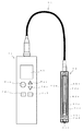
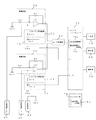
まず、図11に示す外観図、図12に示すブロック図を用いて、本発明に係わる酸化還元電位計の具体的な構成について説明する。 First, a specific configuration of the oxidation-reduction potentiometer according to the present invention will be described with reference to an external view shown in FIG. 11 and a block diagram shown in FIG.
実施例4としての酸化還元電位計は、正面に入力部4及び表示器5を有する本体1と、作用電極48、参照電極49及び導電率測定電極42を兼有するセンサー41と、本体1とセンサー41とを接続するケーブル3とを外見上に備え、増幅回路8、導電率測定回路43、A/D変換器44、インピーダンス低減回路45、低減回路切替スイッチ46、導電率測定切替スイッチ47、EEPROM12及びマイクロコンピュータ13を配設する電子基板と、電源部14とを本体1の内部に備えることにより、全体を大略構成する。
The oxidation-reduction potentiometer as Example 4 includes a
入力部4は、ONキー4a、スタートキー4b、モードキー4c、+キー4d及び−キー4eから成り、電力供給・測定開始・切替等をするための入力をする。ONキー4aは、電源部14から電気系統各部に電力の供給を開始するためものである。スタートキー4bは、測定を開始するためのである。モードキー4cは、調整モードと測定モードとを切替えるためのものである。+キー4d、−キー4eは、表示器に表示する項目や数値等を選択をするためのものである。
The
表示器5は、入力状況・測定結果・各種モード・電池残量等を表示する。
The
センサー41は、内側ガラス管(図11において透明にて示す。)41aの外側に間隙を設けて覆う外側ガラス管(図11において透明にて示す。)41bを形成し、内側ガラス管41aの外側から外側ガラス管41bの外側にかけて白金(Pt)41cと導電率測定電極42とを配設し、内側ガラス管41aの内部に、銀(Ag)に塩化銀(AgCl)を被覆した内部電極41dを設けるとともに液状又はゲル状の塩化ナトリウム(NaCl)又は塩化カリウム(KCl)を充填し、内側ガラス管41aの内部から内側ガラス管41aかつ外側ガラス管41bの外側にかけて液絡部41eを配設し、白金(Pt)41cと内部電極41dとには電子基板につながる導線41f、41g、41hが接続する。
The
なお、白金(Pt)41c部分が作用電極48に該当し、内側ガラス管41a、内部電極41d、塩化ナトリウム(NaCl)又は塩化カリウム(KCl)、液絡部41eにかけての部分が参照電極49に該当する。
The platinum (Pt) 41c portion corresponds to the working
電源部14は、電気系統各部に電力を供給する。
The
増幅回路8は、測定した作用電極48により発生する酸化還元反応の程度を表す電位と参照電極49により発生する基準となる電位との差である電極間電圧(アナログ信号)を増幅する。導電率測定回路43は、導電率測定電極42により発生する電位と作用電極48により発生する電位との差である電極間電圧(アナログ信号)を増幅する。A/D変換器44は、増幅回路8又は導電率測定回路43により増幅された電極間電圧をデジタル信号に変換する。
The amplifying
インピーダンス低減回路45は、作用電極48と参照電極49との間に低減回路切替スイッチ46により非接続状態及び接続状態となり得るように配設する抵抗値の異なる複数の抵抗R11、R12から成り、液に浸けた際における作用電極48と参照電極49との間に生ずるインピーダンスを低減する。
The
低減回路切替スイッチ46は、マイクロコンピュータ13からの制御信号に基づいてインピーダンス低減回路45を非接続状態及び接続状態へと切替える。導電率測定切替スイッチ47は、マイクロコンピュータ13からの制御信号に基づいて作用電極48の接続を導電率測定回路43又は増幅回路8に切替える。
The reduction
EEPROM12は、対比係数記憶部12aを兼有し、各種データを記憶する。対比係数記憶部12aは、後述する対比係数演算部13aにより演算した対比係数を記憶する。
The EEPROM 12 also has a contrast
マイクロコンピュータ13は、対比係数演算部13aと酸化還元電位演算部13bと導電率判定部13cとを兼有し、各種データ等について演算し、また、低減回路切替スイッチ46・導電率測定切替スイッチ47の切替え、各種データの判定等について制御する。
The
対比係数演算部13aは、インピーダンス低減回路45が非接続状態におけるA/D変換器44からの複数の基準液についての電極間電圧(基準液電圧)と、インピーダンス低減回路45が接続状態におけるA/D変換器44からの複数の基準液についての電極間電圧(基準液電圧)とに基づいて各基準液に対する対比係数を演算する。より具体的には、次の演算式(5)、(6)に示すように、インピーダンス低減回路が非接続状態におけるA/D変換器44からのある基準液についての電極間電圧Vra0をインピーダンス低減回路45が接続状態におけるA/D変換器44からのある基準液についての電極間電圧Vra1で除すことによって、ある基準液に対する対比係数k1を演算し、インピーダンス低減回路45が非接続状態におけるA/D変換器44からの別の基準液についての電極間電圧Vrb0を、インピーダンス低減回路45が接続状態におけるA/D変換器44からの別の基準液についての電極間電圧Vrb1で除すことによって、別の基準液に対する対比係数k2を演算する。
k1=Vra0/Vra1 ・・・ (5)
k2=Vrb0/Vrb1 ・・・ (6)
The contrast coefficient calculation unit 13a includes an interelectrode voltage (reference liquid voltage) for a plurality of reference liquids from the A /
k1 = Vra0 / Vra1 (5)
k2 = Vrb0 / Vrb1 (6)
酸化還元電位演算部13bは、マイクロコンピュータ13からの制御信号に基づいてインピーダンス低減回路45を被験液の導電率に対応する接続状態へと切替えた際に、インピーダンス低減回路45が接続状態におけるA/D変換器44からの電極間電圧と、対比係数記憶部12aに記憶した複数の対比係数のうちから被験液の導電率に対応する対比係数とに基づいて酸化還元電位を演算する。より具体的には、次の演算式(7)、(8)に示すように、インピーダンス低減回路45が被験液の導電率に対応する接続状態におけるA/D変換器44からの電極間電圧Vs1又はVs2に、対比係数記憶部12aに記憶した複数の対比係数のうちから被験液の導電率に対応する対比係数k1又はk2を乗じることによって、インピーダンス低減回路45が非接続状態におけるA/D変換器44からの電極間電圧(被験液電圧)、すなわち、酸化還元電位Vs0を演算する。
Vs0=k1×Vs1 ・・・ (7)
Vs0=k2×Vs2 ・・・ (8)
When the
Vs0 = k1 × Vs1 (7)
Vs0 = k2 × Vs2 (8)
導電率判定部13cは、A/D変換器44からの被験液導電率と予め記憶している基礎導電率とを比較し、酸化還元電位演算部13bで用いる対比係数を選択する。
The conductivity determination unit 13c compares the test solution conductivity from the A /
なお、低減回路切替スイッチ46及びマイクロコンピュータ13にて低減回路切替手段を構成する。また、低減回路切替スイッチ46及びマイクロコンピュータ13にて導電率測定切替手段を構成する。また、導電率測定電極42、導電率測定回路43、A/D変換器44及びマイクロコンピュータ13にて導電率測定手段を構成する。また、増幅回路8、A/D変換器44及びマイクロコンピュータ13にて電極間電圧測定手段を構成する。また、低減回路切替手段、電極間電圧測定手段、対比係数演算部13a、対比係数記憶部12a及び酸化還元電位演算部13bにて酸化還元電位測定手段を構成する。
The reduction
次に、図13に示す調整モードにおけるフローチャート、図14に示す通常モードにおけるフローチャートを用いて、本発明に係わる酸化還元電位計の具体的な操作及び動作について説明する。 Next, specific operations and operations of the oxidation-reduction potentiometer according to the present invention will be described using the flowchart in the adjustment mode shown in FIG. 13 and the flowchart in the normal mode shown in FIG.
まず、調整モードにおける具体的な操作及び動作について詳述する。 First, specific operations and operations in the adjustment mode will be described in detail.
ONキー4aが押されると電源部14から電気系統各部に電力を供給し、図14に示すフローチャートに沿って後に説明する通常モードに入る(ステップG61)。そして、この後、モードキー4cが押されると図13に示すフローチャートに沿った調整モードに入る(ステップC61)。
When the ON key 4a is pressed, power is supplied from the
続いて、センサー41が既知の基準液A(基準液A導電率>基礎導電率)に浸けられ、スタートキー4bが押されると(ステップC62)、マイクロコンピュータ13のポートP1、P2、P5からのOFF制御信号に基づいて低減回路切替スイッチ(Sw1、Sw2)46及び導電率測定切替スイッチ47のうちのSw5がオフし、マイクロコンピュータ13のポートP6からのON制御信号に基づいて導電率測定切替スイッチ47のうちのSw6がオンし、作用電極・参照電極間が選択状態となり、かつ、インピーダンス低減回路45が非接続状態となる(ステップC63)。なお、基礎導電率とは、後述において、被験液の導電率が基準液A導電率寄りなのか基準液B導電率寄りなのかを判定するために基準とする導電率のことである。
Subsequently, when the
続いて、この時の作用電極48と参照電極49との間に発生する基準液Aに対する電極間電圧(アナログ信号)を増幅回路8により増幅し、A/D変換器44によりデジタル信号に変換し、マイクロコンピュータ13により非接続時の電極間電圧(基準液A電圧)Vra0として演算する(ステップC64)。
Subsequently, the interelectrode voltage (analog signal) for the standard solution A generated between the working
続いて、マイクロコンピュータ13のポートP1からのON制御信号に基づいて低減回路切替スイッチSw1がオンし、インピーダンス低減回路45のうちの基準液A導電率に対応するものが接続状態となる(ステップC65)。
Subsequently, the reduction circuit changeover switch Sw1 is turned on based on the ON control signal from the port P1 of the
続いて、この時の作用電極48と参照電極49との間に発生する基準液Aに対する電極間電圧(アナログ信号)を増幅回路8により増幅し、A/D変換器44によりデジタル信号に変換し、マイクロコンピュータ13により基準液A導電率に対応する抵抗R11が接続時の電極間電圧(基準液A電圧)Vra1として演算する(ステップC66)。
Subsequently, the interelectrode voltage (analog signal) for the standard solution A generated between the working
続いて、対比係数演算部13aにおいて、上述した演算式(5)に示すように、すべてが非接続時の基準液Aに対する電極間電圧(基準液電圧)Vra0を、基準液A導電率に対応する抵抗R11が接続時の電極間電圧(基準液A電圧)Vra1で除すことによって、基準液A導電率に対応する対比係数k1を演算し(ステップC67)、対比係数記憶部12aにおいて、この演算した基準液A導電率に対応する対比係数k1を記憶する(ステップC68)。
Subsequently, in the contrast coefficient calculation unit 13a, as shown in the calculation formula (5) described above, the interelectrode voltage (reference liquid voltage) Vra0 with respect to the reference liquid A when all are not connected corresponds to the reference liquid A conductivity. By dividing the resistor R11 to be connected by the interelectrode voltage (reference liquid A voltage) Vra1 at the time of connection, a contrast coefficient k1 corresponding to the reference liquid A conductivity is calculated (step C67), and this is stored in the contrast
続いて、センサー41が既知の基準液B(基準液B導電率≦基礎導電率)に浸けられ、スタートキー46が押されると(ステップC69)、マイクロコンピュータ13のポートP1、P2、P5からのOFF制御信号に基づいて低減回路切替スイッチ(Sw1、Sw2)46及び導電率測定切替スイッチ47のうちのSw5がオフし、マイクロコンピュータ13のポートP6からのON制御信号に基づいて導電率測定切替スイッチ47のうちのSw6がオンし、作用電極・参照電極間が選択状態となり、かつ、インピーダンス低減回路45が非接続状態となる(ステップC70)。
Subsequently, when the
続いて、この時の作用電極48と参照電極49との間に発生する基準液Bに対する電極間電圧(アナログ信号)を増幅回路8により増幅し、A/D変換器44によりデジタル信号に変換し、マイクロコンピュータ13により非接続時の電極間電圧(基準液B電圧)Vrb0として演算する(ステップC71)。
Subsequently, the interelectrode voltage (analog signal) for the standard solution B generated between the working
続いて、マイクロコンピュータ13のポートP2からのON制御信号に基づいて低減回路切替スイッチ46のうちのSw2がオンし、インピーダンス低減回路45のうちの基準液B導電率に対応する抵抗R12が接続状態となる(ステップC72)。
Subsequently, Sw2 of the reduction
続いて、この時の作用電極48と参照電極49との間に発生する基準液Bに対する電極間電圧(アナログ信号)を増幅回路8により増幅し、A/D変換器44によりデジタル信号に変換し、マイクロコンピュータ13により基準液B導電率に対応する抵抗R12が接続時の電極間電圧(基準液B電圧)Vrb1として演算する(ステップC73)。
Subsequently, the interelectrode voltage (analog signal) for the standard solution B generated between the working
続いて、対比係数演算部13aにおいて、上述した演算式(6)に示すように、すべてが非接続時の基準液Bに対する電極間電圧(基準液電圧)Vrb0を、基準液B導電率に対応する抵抗R12が接続時の電極間電圧(基準液B電圧)Vrb1で除すことによって、基準液B導電率に対応する対比係数k2を演算し(ステップC74)、対比係数記憶部12aにおいて、この演算した基準液B導電率に対応する対比係数k2を記憶すると(ステップC75)、この調整モードを抜ける(ステップC76)。
Subsequently, in the contrast coefficient calculation unit 13a, as shown in the calculation formula (6) described above, the interelectrode voltage (reference liquid voltage) Vrb0 with respect to the reference liquid B when all are not connected corresponds to the reference liquid B conductivity. By dividing the resistor R12 to be connected by the interelectrode voltage (reference liquid B voltage) Vrb1 at the time of connection, a contrast coefficient k2 corresponding to the reference liquid B conductivity is calculated (step C74), and this is stored in the contrast
次に、通常モードにおける具体的な操作及び動作について詳述する。 Next, specific operations and operations in the normal mode will be described in detail.
ONキー4aが押された直後、又は調整モードを抜けた後は、図14に示すフローチャートに沿った通常モードと入る(ステップG61)。 Immediately after the ON key 4a is pressed or after exiting the adjustment mode, the normal mode according to the flowchart shown in FIG. 14 is entered (step G61).
続いて、センサー41が被験液に浸けられ、スタートキー4bが押されると(ステップG62)、マイクロコンピュータ13のポートP1、P2、P6からのOFF制御信号に基づいて低減回路切替スイッチ(Sw1、Sw2)46及び導電率測定切替スイッチ47のうちのSw6がオフし、マイクロコンピュータ13のポートP5からのON制御信号に基づいて導電率測定切替スイッチ47のうちのSw5がオンし、作用電極・導電率測定電極間が選択状態となり、かつ、インピーダンス低減回路41が非接続状態となる(ステップG63)。
Subsequently, when the
続いて、導電率測定回路43において、導電率測定電極41により発生する電位と作用電極48により発生する電位との差である電極間電圧(アナログ信号)を増幅し、A/D変換器44において、電極間電圧をデジタル信号に変換し、導電率判定部13cにおいて、被験液の導電率を演算する(ステップG64)。
Subsequently, the conductivity measuring circuit 43 amplifies an interelectrode voltage (analog signal) which is a difference between the potential generated by the
続いて、この演算した被験液の導電率が基礎導電率よりも大きいか否かを判定する(ステップG65)。 Subsequently, it is determined whether or not the calculated conductivity of the test solution is larger than the basic conductivity (step G65).
続いて、この判定結果が基礎導電率よりも大きい場合には(ステップG65でYES)、対比係数記憶部に記憶した基準液A導電率に対応する対比係数k1を呼び出す(ステップG66)。 Subsequently, when the determination result is larger than the basic conductivity (YES in Step G65), the contrast coefficient k1 corresponding to the reference liquid A conductivity stored in the contrast coefficient storage unit is called (Step G66).
続いて、マイクロコンピュータ13のポートP5からのOFF制御信号に基づいて導電率測定切替スイッチ47のうちのSw5がオフし、マイクロコンピュータ13のポートP1、P6からのON制御信号に基づいて低減回路切替スイッチ46のうちのSw1及び導電率測定切替スイッチ47のうちのSw6がオンし、作用電極・参照電極間が選択状態となり、かつ、インピーダンス低減回路45が基準液A導電率に対応した接続状態となる(ステップG67)。
Subsequently, Sw5 of the conductivity
続いて、この時の作用電極48と参照電極49との間に発生する被験液に対する電極間電圧(アナログ信号)を増幅回路8により増幅し、A/D変換器44によりデジタル信号に変換し、マイクロコンピュータ13により接続時の電極間電圧(被験液電圧)Vs1として演算する(ステップG68)。
Subsequently, the interelectrode voltage (analog signal) for the test liquid generated between the working
続いて、酸化還元電位演算部13bにおいて、上述した演算式(7)に示すように、接続時の電極間電圧(被験液電圧)Vs1に、対比係数記憶部12aに記憶した対応する対比係数k1を乗じることによって、非接続時の電極間電圧(被験液電圧)、すなわち、酸化還元電位Vs0を演算する(ステップG69)。
Subsequently, in the oxidation-reduction
ステップG65において、一方、この判定結果が基礎導電率よりも大きくない場合、すなわち、この判定結果が基礎導電率以下である場合には(ステップG65でNO)、対比係数記憶部12aに記憶した基準液B導電率に対応する対比係数k2を呼び出す(ステップG70)。
On the other hand, when the determination result is not larger than the basic conductivity in step G65, that is, when the determination result is equal to or lower than the basic conductivity (NO in step G65), the reference stored in the contrast
続いて、マイクロコンピュータ13のポートP5からのOFF制御信号に基づいて導電率測定切替スイッチ47のうちのSw5がオフし、マイクロコンピュータ13のポートP2、P6からのON制御信号に基づいて低減回路切替スイッチ46のうちのSw2及び導電率測定切替スイッチ47のうちのSw6がオンし、作用電極・参照電極間が選択状態となり、かつ、インピーダンス低減回路45が基準液B導電率に対応した接続状態となる(ステップG71)。
Subsequently, Sw5 of the conductivity
続いて、この時の作用電極48と参照電極49との間に発生する被験液に対する電極間電圧(アナログ信号)を増幅回路8により増幅し、A/D変換器44によりデジタル信号に変換し、マイクロコンピュータ13により接続時の電極間電圧(被験液電圧)Vs2として演算する(ステップG72)。
Subsequently, the interelectrode voltage (analog signal) for the test liquid generated between the working
続いて、酸化還元電位演算部13bにおいて、上述した演算式(8)に示すように、接続時の電極間電圧(被験液電圧)Vs2に、対比係数記憶部12aに記憶した対応する対比係数k2を乗じることによって、非接続時の電極間電圧(被験液電圧)、すなわち、酸化還元電位Vs0を演算する(ステップG73)。
Subsequently, in the oxidation-reduction
ステップG69又はステップG73に続いて、それぞれにおける結果を表示器に表示し(ステップG74)、以降、ステップG62に戻り、処理を繰り返すことが可能となる。 Subsequent to step G69 or step G73, the result of each is displayed on the display (step G74), and thereafter, the process returns to step G62 and the process can be repeated.
まず、図11に示す外観図、図15に示すブロック図を用いて、本発明に係わる酸化還元電位計の具体的な構成について説明する。 First, a specific configuration of the oxidation-reduction potentiometer according to the present invention will be described with reference to an external view shown in FIG. 11 and a block diagram shown in FIG.
実施例5としての酸化還元電位計は、正面に入力部4及び表示器5を有する本体1と、作用電極48、参照電極49及び水没測定電極51を兼有するセンサー41と、本体1とセンサー41とを接続するケーブル3とを外見上に備え、増幅回路8、水没測定回路52、A/D変換器44、インピーダンス低減回路10、低減回路切替スイッチ11、水没測定切替スイッチ54、EEPROM12及びマイクロコンピュータ13を配設する電子基板と、電源部14とを本体1の内部に備えることにより、全体を大略構成する。
The oxidation-reduction potentiometer as Example 5 includes a
なお、入力部4、表示器5、電源部14、増幅回路8、インピーダンス低減回路10、低減回路切替スイッチ11、EEPROM12、対比係数演算部13a及び酸化還元電位演算部13bについては、実施例1と同様であるので、詳述を省略する。
The
センサー41は、実施例4において、図11に表して説明したものと同様の形態を成し、導電率測定電極42が水没測定電極51に置き換わったものである。
The
水没測定回路52は、水没測定電極51と共に水没検出電位を生じさせるものである。 The submergence measurement circuit 52 generates a submergence detection potential together with the submergence measurement electrode 51.
A/D変換器44は、増幅回路8や水没測定電極51・水没測定回路52からの電圧をデジタル信号に変換する。
The A /
水没測定切替スイッチ54は、マイクロコンピュータ13からの制御信号に基づいて増幅回路8への接続を接地状態に切替える。
The submergence measurement changeover switch 54 switches the connection to the
マイクロコンピュータ13は、対比係数演算部13aと酸化還元電位演算部13bと水没判定部13dとを兼有し、各種データ等について演算し、また、低減回路切替スイッチ11・水没測定切替スイッチ54の切替え、各種データの判定等について制御する。
The
水没判定部13dは、A/D変換器44からの水没測定電圧と予め記憶している判定電圧とを比較し、センサー41が液に浸かっている状態なのか否かを判定する。
The submergence determination unit 13d compares the submergence measurement voltage from the A /
なお、水没測定切替スイッチ54及びマイクロコンピュータ13にて水没測定切替手段を構成する。また、水没測定電極51、水没測定回路52、A/D変換器44及びマイクロコンピュータ13にて水没測定手段を構成する。
The submergence measurement switching switch 54 and the
次に、図16に示す調整モードにおけるフローチャート、図17に示すメインフローチャートを用いて、本発明に係わる酸化還元電位計の具体的な操作及び動作について説明する。 Next, specific operations and operations of the oxidation-reduction potentiometer according to the present invention will be described using the flowchart in the adjustment mode shown in FIG. 16 and the main flowchart shown in FIG.
まず、調整モードにおける具体的な操作及び動作について詳述する。 First, specific operations and operations in the adjustment mode will be described in detail.
ONキー4aが押されると電源部14から電気系統各部に電力を供給しスタンバイ状態となり、その後、モードキー4cが押される毎に調整モードと通常モードとが切替るので、調整モードを選択し、図16に示すフローチャートに沿った調整モードに入る(ステップC81)。
When the ON key 4a is pressed, power is supplied from the
続いて、センサー41が基準液に浸けられ、スタートキー46が押されると(ステップC82)、マイクロコンピュータ13のポートP1、P7からのOFF制御信号に基づいて低減回路切替スイッチ(Sw1)11及び水没測定切替スイッチ(Sw7)54がオフし、作用電極・参照電極間での測定状態となり、かつ、インピーダンス低減回路10が非接続状態となる(ステップC83)。
Subsequently, when the
続いて、この時の作用電極48と参照電極49との間に発生する電極間電圧(アナログ信号)を増幅回路8により増幅し、A/D変換器44によりデジタル信号に変換し、マイクロコンピュータ13により非接続時の電極間電圧(基準液電圧)Vr0として演算する(ステップC84)。
Subsequently, the interelectrode voltage (analog signal) generated between the working
続いて、マイクロコンピュータ13のポートP1からのON制御信号に基づいて低減回路切替スイッチ(Sw1)11がオンし、インピーダンス低減回路10が接続状態となる(ステップC85)。
Subsequently, the reduction circuit selector switch (Sw1) 11 is turned on based on the ON control signal from the port P1 of the
続いて、この時の作用電極48と参照電極49との間に発生する電極間電圧(アナログ信号)を増幅回路8により増幅し、A/D変換器44によりデジタル信号に変換し、マイクロコンピュータ13により接続時の電極間電圧(基準液電圧)Vr1として演算する(ステップC86)。
Subsequently, the interelectrode voltage (analog signal) generated between the working
続いて、対比係数演算部13aにおいて、実施例1での演算式(1)に示すように、非接続の電極間電圧(基準液電圧)Vr0を、接続時の電極間電圧(基準液電圧)Vr1で除すことによって、対比係数k1を演算し(ステップC87)、対比係数記憶部12aにおいて、この演算した対比係数k1を記憶すると(ステップC88)、この調整モードを抜ける(ステップC89)。
Subsequently, in the contrast coefficient calculation unit 13a, as shown in the calculation formula (1) in the first embodiment, the non-connected interelectrode voltage (reference liquid voltage) Vr0 is changed to the interelectrode voltage (reference liquid voltage) at the time of connection. By dividing by Vr1, the contrast coefficient k1 is calculated (step C87), and when the calculated contrast coefficient k1 is stored in the contrast
次に、装置作動(通常モード)における具体的な操作及び動作について詳述する。 Next, specific operations and operations in the device operation (normal mode) will be described in detail.
ONキー4aが押された直後、又は調整モードを抜けた後は、電源部14から電気系統各部に電力を供給し(ステップG81)、マイクロコンピュータ13のポートP1からのOFF制御信号に基づいて低減回路切替スイッチ(Sw1)11がオフし、マイクロコンピュータ13のポートP7からのON制御信号に基づいて水没測定切替スイッチ(Sw7)54がオンし、スタンバイ状態となる(ステップG82)。
Immediately after the ON key 4a is pressed or after exiting the adjustment mode, power is supplied from the
続いて、モードキー4cが押される毎に調整モードと通常モードとが切替るので、通常モードを選択すると(ステップG83)、水没測定電極51と作用電極48との電極間電圧(アナログ信号)をA/D変換器44によりデジタル信号に変換し、マイクロコンピュータ13により水没測定電圧Vwとして取り込む(ステップG84)。
Then, the adjustment mode and so the normal mode and the switches mode key 4c is for each pushed, when the normal mode is selected (step G 83), the inter-electrode voltage of the submerged measuring electrode 51 and the working electrode 48 (analog signal) It was converted to a digital signal by the a /
続いて、水没判定部13dにおいて、この水没測定電圧Vwが判別電圧よりも大きいか否かを判定する(ステップG85)。 Subsequently, the submergence determination unit 13d determines whether or not the submergence measurement voltage Vw is larger than the determination voltage (step G85).
続いて、判別電圧よりも大きくない場合には(ステップG85でNO)、ステップG84に戻り、処理を繰り返すことが可能となる。一方、判別電圧よりも大きい場合には(ステップG85でYES)、スタートキー4bが押されたかを判定する(ステップG86)。 Subsequently, when the voltage is not greater than the determination voltage (NO in step G85), the process returns to step G84, and the process can be repeated. On the other hand, if it is greater than the discrimination voltage (YES in step G85), it is determined whether the start key 4b has been pressed (step G86).
続いて、スタートキー4bが押されない場合には(ステップG86でNO)、ステップG84に戻り、処理を繰り返すことが可能となる。一方、スタートキー4bが押された場合には(ステップG86でYES)、マイクロコンピュータ13のポートP1からのON制御信号に基づいて低減回路切替スイッチ(Sw1)11がオンし、マイクロコンピュータ13のポートP7からのOFF制御信号に基づいて水没測定切替スイッチ(Sw7)53がオフし、作用電極・参照電極間での測定状態となり、かつ、インピーダンス低減回路10が接続状態となる(ステップG87)。
Subsequently, when the start key 4b is not pressed (NO in step G86), the process returns to step G84, and the process can be repeated. On the other hand, when the start key 4b is pressed (YES in step G86), the reduction circuit selector switch (Sw1) 11 is turned on based on the ON control signal from the port P1 of the
続いて、この時の作用電極48と参照電極49との間に発生する電極間電圧(アナログ信号)を増幅回路8により増幅し、A/D変換器44によりデジタル信号に変換し、マイクロコンピュータ13により接続時の電極間電圧(被験液電圧)Vs1として演算する(ステップG88)。
Subsequently, the interelectrode voltage (analog signal) generated between the working
続いて、酸化還元電位演算部13bにおいて、上述した演算式(2)に示すように、接続時の電極間電圧(被験液電圧)Vs1に対比係数記憶部12aに記憶している対比係数k1を乗じることによって、非接続時の電極間電圧(被験液電圧)、すなわち、酸化還元電位Vs0を演算し(ステップG89)、この結果を表示器に表示する(ステップG90)。
Subsequently, in the oxidation-reduction
続いて、マイクロコンピュータ13のポートP1からのOFF制御信号に基づいて低減回路切替スイッチ(Sw1)11がオフし、マイクロコンピュータ13のポートP7からのON制御信号に基づいて水没測定切替スイッチ(Sw7)53がオンし(ステップG91)、以降、ステップG84に戻り、処理を繰り返すことが可能となる。
Subsequently, the reduction circuit changeover switch (Sw1) 11 is turned off based on the OFF control signal from the port P1 of the
まず、図18に示す外観図、図19に示すブロック図を用いて、本発明に係わる酸化還元電位計の具体的な構成について説明する。 First, a specific configuration of the oxidation-reduction potentiometer according to the present invention will be described with reference to an external view shown in FIG. 18 and a block diagram shown in FIG.
実施例6としての酸化還元電位計は、正面に入力部64及び表示器65を有する本体61と、反応面積が小さな作用電極小66、反応面積の大きな作用電極大67及び参照電極68を兼有するセンサー62と、本体61とセンサー62とを接続するケーブル63とを外見上に備え、増幅回路69、A/D変換器70、インピーダンス低減回路71、低減回路切替スイッチ72、作用電極切替スイッチ73、EEPROM74及びマイクロコンピュータ75を配設する電子基板と、電源部76とを本体61の内部に備えることにより、全体を大略構成する。
The oxidation-reduction potentiometer as Example 6 has a main body 61 having an
入力部64は、ONキー64a、スタートキー64b、モードキー64c、+キー64d及び−キー64eから成り、電力供給・測定開始・切替等をするための入力をする。ONキー64aは、電源部76から電気系統各部に電力の供給を開始するためものである。スタートキー64bは、測定を開始するためのである。モードキー64cは、調整モードと測定モードとを切替えるためのものである。+キー64d、−キー64eは、表示器65に表示する項目や数値等を選択をするためのものである。
The
表示器65は、入力状況・測定結果・各種モード・電池残量等を表示する。 The display 65 displays the input status, measurement results, various modes, the remaining battery level, and the like.
センサー62は、内側ガラス管(図18において透明にて示す。)62aの外側に間隙を設けて覆う外側ガラス管(図18において透明にて示す。)62bを形成し、内側ガラス管62aの外側から外側ガラス管62bの外側にかけて面積の小さな白金(Pt)小62cと面積の大きな白金(Pt)大62dとを配設し、内側ガラス管62aの内部に、銀(Ag)に塩化銀(AgCl)を被覆した内部電極62eを設けるとともに液状又はゲル状の塩化ナトリウム(NaCl)又は塩化カリウム(KCl)を充填し、内側ガラス管62aの内部から内側ガラス管62aかつ外側ガラス管62bの外側にかけて液絡部62fを配設し、白金(Pt)小62cと白金(Pt)大62dと内部電極62eとには電子基板につながる導線62g、62h、62iが接続する。
The
なお、白金(Pt)小62cの部分が作用電極小66に該当し、白金(Pt)大62dの部分が作用電極大67に該当し、内側ガラス管62a、内部電極62e、塩化ナトリウム(NaCl)又は塩化カリウム(KCl)、液絡部62fにかけての部分が参照電極68に該当する。 The platinum (Pt) small 62c portion corresponds to the working electrode small 66, the platinum (Pt) large 62d portion corresponds to the working electrode large 67, the inner glass tube 62a, the internal electrode 62e, and sodium chloride (NaCl). Alternatively, a portion extending from potassium chloride (KCl) and the liquid junction 62 f corresponds to the reference electrode 68.
電源部76は、電気系統各部に電力を供給する。 The power supply unit 76 supplies power to each part of the electrical system.
増幅回路69は、測定した作用電極小66又は作用電極大67により発生する酸化還元反応の程度を表す電位と参照電極68により発生する基準となる電位との差である電極間電圧(アナログ信号)を増幅する。A/D変換器70は、増幅回路69により増幅された電極間電圧をデジタル信号に変換する。
The amplifying
インピーダンス低減回路71は、作用電極小66と参照電極67との間に低減回路切替スイッチ72により非接続状態及び接続状態となり得るように配設する抵抗R14と、作用電極大67と参照電極68との間に低減回路切替スイッチ72により非接続状態及び接続状態となり得るように配設する抵抗R11とから成り、液に浸けた際における作用電極小66と参照電極68との間、又は作用電極大67と参照電極68との間に生ずるインピーダンスを低減する。
The impedance reduction circuit 71 includes a resistor R14 disposed between the small working
低減回路切替スイッチ72は、マイクロコンピュータ75からの制御信号に基づいてインピーダンス低減回路71を非接続状態及び接続状態へと切替える。作用電極切替スイッチ73は、マイクロコンピュータ75からの制御信号に基づいて増幅回路69への接続を作用電極小66又は作用電極大67に切替える。
The reduction circuit selector switch 72 switches the impedance reduction circuit 71 between a non-connected state and a connected state based on a control signal from the
EEPROM74は、対比係数記憶部74aを兼有し、各種データを記憶する。対比係数記憶部74aは、後述する対比係数演算部75aにより演算した各対比係数を記憶する。 The EEPROM 74 also has a contrast coefficient storage unit 74a and stores various data. The comparison coefficient storage unit 74a stores each comparison coefficient calculated by a comparison coefficient calculation unit 75a described later.
マイクロコンピュータ75は、対比係数演算部75aと酸化還元電位演算部75bとを兼有し、各種データ等について演算し、また、低減回路切替スイッチ・作用電極切替スイッチの切替え、各種データの判定等について制御する。
The
対比係数演算部75aは、インピーダンス低減回路71が非接続状態におけるA/D変換器70からの電極間電圧(基準液電圧)と、インピーダンス低減回路71が接続状態におけるA/D変換器70からの各作用電極66、67と参照電極68との各電極間電圧(基準液電圧)とに基づいて各対比係数を演算する。より具体的には、次の演算式(9)に示すように、インピーダンス低減回路71が非接続状態におけるA/D変換器70からの作用電極大67と参照電極68との電極間電圧Vrg0をインピーダンス低減回路71が接続状態におけるA/D変換器70からの作用電極大67と参照電極68との電極間電圧Vrg1で除すことによって、対比係数kg1を演算し、また、次の演算式(10)に示すように、インピーダンス低減回路71が非接続状態におけるA/D変換器70からの作用電極小66と参照電極68との電極間電圧Vrs0をインピーダンス低減回路71が接続状態におけるA/D変換器70からの作用電極小66と参照電極68との電極間電圧Vrs1で除すことによって、対比係数ks1を演算する。
kg1=Vrg0/Vrg1 ・・・ (9)
ks1=Vrs0/Vrs1 ・・・ (10)
The contrast coefficient calculation unit 75a is configured such that the interelectrode voltage (reference liquid voltage) from the A /
kg1 = Vrg0 / Vrg1 (9)
ks1 = Vrs0 / Vrs1 (10)
酸化還元電位演算部75bは、マイクロコンピュータ75からの制御信号に基づいてインピーダンス低減回路71を接続状態へと切替えた際に、インピーダンス低減回路71が接続状態におけるA/D変換器70からの各作用電極66、67と参照電極68との電極間電圧と、対比係数記憶部74aに記憶した各対比係数とに基づいて酸化還元電位を演算する。より具体的には、次の演算式(11)に示すように、インピーダンス低減回路71が接続状態におけるA/D変換器70からの作用電極小66と参照電極68との電極間電圧Vss1に対比係数記憶部74aに記憶した対比係数ks1を乗じることによって、インピーダンス低減回路71が非接続状態におけるA/D変換器70からの作用電極小66と参照電極68との電極間電圧(被験液電圧)、すなわち、酸化還元電位Vss0を演算し、また、次の演算式(12)に示すように、インピーダンス低減回路71が接続状態におけるA/D変換器70からの作用電極大67と参照電極68との電極間電圧Vsg1に対比係数記憶部74aに記憶した対比係数kg1を乗じることによって、インピーダンス低減回路71が非接続状態におけるA/D変換器70からの作用電極大67と参照電極68との電極間電圧(被験液電圧)、すなわち、酸化還元電位Vsg0を演算する。
Vss0=ks1×Vss1 ・・・ (11)
Vsg0=kg1×Vsg1 ・・・ (12)
When the impedance reduction circuit 71 switches the impedance reduction circuit 71 to the connected state based on a control signal from the
Vss0 = ks1 × Vss1 (11)
Vsg0 = kg1 × Vsg1 (12)
なお、低減回路切替スイッチ72及びマイクロコンピュータ75にて低減回路切替手段を構成する。作用電極切替スイッチ73及びマイクロコンピュータ75にて作用電極切替手段を構成する。また、増幅回路69、A/D変換器70及びマイクロコンピュータ75にて電極間電圧測定手段を構成する。また、低減回路切替手段、電極間電圧測定手段、対比係数演算部75a、対比係数記憶部74a及び酸化還元電位演算部75bにて酸化還元電位測定手段を構成する。
The reduction circuit switching switch 72 and the
次に、図20に示す調整モードにおけるフローチャート、図21に示す通常モードにおけるフローチャートを用いて、本発明に係わる酸化還元電位計の具体的な操作及び動作について説明する。 Next, specific operations and operations of the oxidation-reduction potentiometer according to the present invention will be described using the flowchart in the adjustment mode shown in FIG. 20 and the flowchart in the normal mode shown in FIG.
まず、調整モードにおける具体的な操作及び動作について詳述する。 First, specific operations and operations in the adjustment mode will be described in detail.
ONキー64aが押されると電源部76から電気系統各部に電力を供給し、図21に示すフローチャートに沿って後に説明する通常モードに入る(ステップG101)。そして、この後、モードキー64cが押されると図20に示すフローチャートに沿った調整モードに入る(ステップC101)。 When the ON key 64a is pressed, power is supplied from the power supply unit 76 to each part of the electrical system, and the normal mode described later is entered along the flowchart shown in FIG. 21 (step G101). Thereafter, when the mode key 64c is pressed, the adjustment mode according to the flowchart shown in FIG. 20 is entered (step C101).
続いて、センサー62が基準液に浸けられ、スタートキーが押されると(ステップC102)、マイクロコンピュータ75のポートP1、P10、P9からのOFF制御信号に基づいて低減回路切替スイッチ(Sw1、Sw10)72及び作用電極切替スイッチ73のうちのSw9がオフし、マイクロコンピュータ75のポートP8からのON制御信号に基づいて作用電極切替スイッチのうちのSw8がオンし、作用電極大・参照電極間が接続状態となり、かつ、インピーダンス低減回路71が非接続状態となる(ステップC103)。
Subsequently, when the
続いて、この時の作用電極大67と参照電極68との間に発生する電極間電圧(アナログ信号)を増幅回路69により増幅し、A/D変換器70によりデジタル信号に変換し、マイクロコンピュータ75により非接続時の電極間電圧(基準液電圧)Vrg0として演算する(ステップC104)。
Subsequently, the inter-electrode voltage (analog signal) generated between the working electrode large 67 and the reference electrode 68 at this time is amplified by the
続いて、マイクロコンピュータ75のポートP1からのON制御信号に基づいて低減回路切替スイッチ72のうちのSw1がオンし、インピーダンス低減回路71のうちの抵抗R11が接続状態となる(ステップC105)。
Subsequently, Sw1 of the reduction circuit selector switch 72 is turned on based on the ON control signal from the port P1 of the
続いて、この時の作用電極大67と参照電極68との間に発生する電極間電圧(アナログ信号)を増幅回路69により増幅し、A/D変換器70によりデジタル信号に変換し、マイクロコンピュータ75により接続時の電極間電圧(基準液電圧)Vrg1として演算する(ステップC106)。
Subsequently, the inter-electrode voltage (analog signal) generated between the working electrode large 67 and the reference electrode 68 at this time is amplified by the
続いて、対比係数演算部75aにおいて、上述した演算式(9)に示すように、すべてが非接続時の電極間電圧(基準液電圧)Vrg0を、抵抗R11が接続時の電極間電圧(基準液電圧)Vrg1で除すことによって、対比係数kg1を演算し(ステップC107)、対比係数記憶部74aにおいて、この演算した対比係数kg1を記憶する(ステップC108)。 Subsequently, in the contrast coefficient calculation unit 75a, as shown in the above-described calculation formula (9), the inter-electrode voltage (reference liquid voltage) Vrg0 when all are not connected and the inter-electrode voltage when the resistor R11 is connected (reference) By dividing by (liquid voltage) Vrg1, the comparison coefficient kg1 is calculated (step C107), and the calculated comparison coefficient kg1 is stored in the comparison coefficient storage unit 74a (step C108).
続いて、マイクロコンピュータ75のポートP1、P8からのOFF制御信号に基づいて低減回路切替スイッチ72のうちのSw1及び作用電極切替スイッチ73のうちのSw8がオフし、マイクロコンピュータ75のポートP9からのON制御信号に基づいて作用電極切替スイッチ73のうちのSw9がオンし、作用電極小・参照電極間が接続状態となり、かつ、インピーダンス低減回路が非接続状態となる(ステップC109)。
Subsequently, based on the OFF control signal from the ports P1 and P8 of the
続いて、この時の作用電極小66と参照電極68との間に発生する電極間電圧(アナログ信号)を増幅回路69により増幅し、A/D変換器70によりデジタル信号に変換し、マイクロコンピュータ75により非接続時の電極間電圧(基準液電圧)Vrs0として演算する(ステップC110)。
Subsequently, the inter-electrode voltage (analog signal) generated between the working electrode small 66 and the reference electrode 68 at this time is amplified by the
続いて、マイクロコンピュータ75のポートP10からのON制御信号に基づいて低減回路切替スイッチ72のうちのSw10がオンし、インピーダンス低減回路71のうちの抵抗R14が接続状態となる(ステップC111)。
Subsequently, Sw10 of the reduction circuit selector switch 72 is turned on based on the ON control signal from the port P10 of the
続いて、この時の作用電極小66と参照電極68との間に発生する電極間電圧(アナログ信号)を増幅回路69により増幅し、A/D変換器70によりデジタル信号に変換し、マイクロコンピュータ75により接続時の電極間電圧(基準液電圧)Vrs1として演算する(ステップC112)。
Subsequently, the inter-electrode voltage (analog signal) generated between the working electrode small 66 and the reference electrode 68 at this time is amplified by the
続いて、対比係数演算部75aにおいて、上述した演算式(10)に示すように、すべてが非接続時の電極間電圧(基準液電圧)Vrs0を、抵抗R14が接続時の電極間電圧(基準液電圧)Vrs1で除すことによって、対比係数ks1を演算し(ステップC113)、対比係数記憶部74aにおいて、この演算した対比係数ks1を記憶すると(ステップC114)、この調整モードを抜ける(ステップC115)。 Subsequently, in the contrast coefficient calculation unit 75a, as shown in the above-described calculation formula (10), the inter-electrode voltage (reference liquid voltage) Vrs0 when all are not connected and the inter-electrode voltage when the resistor R14 is connected (reference) (Comparison voltage) Vrs1 is divided to calculate the contrast coefficient ks1 (step C113). When the calculated contrast coefficient ks1 is stored in the contrast coefficient storage unit 74a (step C114), the adjustment mode is exited (step C115). ).
次に、通常モードにおける具体的な操作及び動作について詳述する。 Next, specific operations and operations in the normal mode will be described in detail.
ONキー64aが押された直後、又は調整モードを抜けた後は、図21に示すフローチャートに沿った通常モードと入る(ステップG101)。 Immediately after the ON key 64a is pressed or after exiting the adjustment mode, the normal mode according to the flowchart shown in FIG. 21 is entered (step G101).
続いて、センサー62が被験液に浸けられ、スタートキー64bが押されると(ステップG102)、マイクロコンピュータ75のポートP1、P8からのOFF制御信号に基づいて低減回路切替スイッチ72のうちのSw1及び作用電極切替スイッチ73のうちのSw8がオフし、マイクロコンピュータ75のポートP10、P9からのON制御信号に基づいて低減回路切替スイッチ72のうちのSw10及び作用電極切替スイッチ73のうちのSw9がオンし、作用電極小・参照電極間が接続状態となり、かつ、インピーダンス低減回路71のうちの抵抗R10が接続状態となる(ステップG103)。
Subsequently, when the
続いて、この時の作用電極小66と参照電極68との間に発生する電極間電圧(アナログ信号)を増幅回路69により増幅し、A/D変換器70によりデジタル信号に変換し、マイクロコンピュータ75により接続時の電極間電圧(被験液電圧)Vss1として演算する(ステップG104)。
Subsequently, the inter-electrode voltage (analog signal) generated between the working electrode small 66 and the reference electrode 68 at this time is amplified by the
続いて、酸化還元電位演算部75bにおいて、上述した演算式(11)に示すように、接続時の電極間電圧(被験液電圧)Vss1に、対比係数記憶部74aに記憶した対比係数ks1を乗じることによって、接続時の電極間電圧(被験液電圧)、すなわち、酸化還元電位Vss0を演算し(ステップG105)、この結果をEEPROM74に記憶し、表示器65に表示する(ステップG106)。 Subsequently, in the oxidation-reduction potential calculation unit 75b, as shown in the above-described calculation formula (11), the interelectrode voltage (test solution voltage) Vss1 at the time of connection is multiplied by the comparison coefficient ks1 stored in the comparison coefficient storage unit 74a. Thus, the interelectrode voltage (test solution voltage) at the time of connection, that is, the oxidation-reduction potential Vss0 is calculated (step G105), and the result is stored in the EEPROM 74 and displayed on the display 65 (step G106).
続いて、マイクロコンピュータ75において、今回記憶した酸化還元電位Vss0(n)から前回記憶した酸化還元電位Vss0(n−1)を減じた絶対値(測定した電圧の変化量)が最低基準変化電圧よりも小さいか否かを判定する(ステップG107)。
Then, the
続いて、この判定結果が最低基準変化電圧よりも小さくない場合には(ステップG107でNO)、ステップG104に戻り、処理を繰り返す。一方、最低基準変化電圧よりも小さい場合には(ステップG107でYES)、マイクロコンピュータ75のポートP10、P9からのOFF制御信号に基づいて低減回路切替スイッチ72のうちのSw10及び作用電極切替スイッチ73のうちのSw9がオフし、マイクロコンピュータ75のポートP1、P8からのON制御信号に基づいて低減回路切替スイッチ72のうちのSw1及び作用電極切替スイッチ73のうちのSw8がオンし、作用電極大・参照電極間が接続状態となり、かつ、インピーダンス低減回路71のうちの抵抗R11が接続状態となる(ステップG108)。
Subsequently, when the determination result is not smaller than the minimum reference change voltage (NO in step G107), the process returns to step G104 and the process is repeated. On the other hand, when the voltage is smaller than the minimum reference change voltage (YES in step G107), Sw10 of the reduction circuit changeover switch 72 and the working
続いて、この時の作用電極大67と参照電極68との間に発生する電極間電圧(アナログ信号)を増幅回路69により増幅し、A/D変換器70によりデジタル信号に変換し、マイクロコンピュータ75により接続時の電極間電圧(被験液電圧)Vsg1として演算する(ステップG109)。
Subsequently, the inter-electrode voltage (analog signal) generated between the working electrode large 67 and the reference electrode 68 at this time is amplified by the
続いて、酸化還元電位演算部75bにおいて、上述した演算式(12)に示すように、接続時の電極間電圧(被験液電圧)Vsg1に、対比係数記憶部74aに記憶した対比係数kg1を乗じることによって、非接続時の電極間電圧(被験液電圧)、すなわち、酸化還元電位Vsg0を演算し(ステップG110)、この結果をEEPROM74に記憶し、表示器65に表示する(ステップG111)。 Subsequently, in the oxidation-reduction potential calculation unit 75b, as shown in the calculation formula (12) described above, the interelectrode voltage (test solution voltage) Vsg1 at the time of connection is multiplied by the comparison coefficient kg1 stored in the comparison coefficient storage unit 74a. Thus, the inter-electrode voltage (test solution voltage) when disconnected, that is, the oxidation-reduction potential Vsg0 is calculated (step G110), and the result is stored in the EEPROM 74 and displayed on the display 65 (step G111).
なお、以降、ステップG102に戻り、処理を繰り返すことが可能となる。 Thereafter, the process can be repeated by returning to step G102.
まず、図18に示す外観図、図22に示すブロック図を用いて、本発明に係わる酸化還元電位計の具体的な構成について説明する。 First, a specific configuration of the oxidation-reduction potentiometer according to the present invention will be described with reference to an external view shown in FIG. 18 and a block diagram shown in FIG.
実施例7としての酸化還元電位計は、正面に入力部64及び表示器65を有する本体61と、反応面積が小さな作用電極小66、反応面積の大きな作用電極大67及び参照電極68を兼有するセンサー62と、本体61とセンサー62とを接続するケーブル63とを外見上に備え、増幅回路69、81、A/D変換器82、インピーダンス低減回路71、低減回路切替スイッチ72、EEPROM74及びマイクロコンピュータ75を配設する電子基板と、電源部76とを本体66の内部に備えることにより、全体を大略構成する。
The oxidation-reduction potentiometer as Example 7 has a main body 61 having an
なお、入力部64、表示器65、センサー62、電源部76、インピーダンス低減回路71、低減回路切替スイッチ72、EEPROM74、対比係数演算部75a及び酸化還元電位演算部75bについては、実施例6と同様であるので、詳述を省略する。
The
増幅回路81は、測定した作用電極小66により発生する酸化還元反応の程度を表す電位と参照電極68により発生する基準となる電位との差である電極間電圧(アナログ信号)を増幅し、また、増幅回路66は、測定した作用電極大67により発生する酸化還元反応の程度を表す電位と参照電極68により発生する基準となる電位との差である電極間電圧(アナログ信号)を増幅する。A/D変換器82は、各々の増幅回路69、81により増幅された各電極間電圧をデジタル信号に変換する。
The amplifying circuit 81 amplifies an inter-electrode voltage (analog signal) which is a difference between a potential indicating the degree of the redox reaction generated by the measured working electrode small 66 and a reference potential generated by the reference electrode 68. The amplifying
マイクロコンピュータ75は、対比係数演算部75aと酸化還元電位演算部75bとを兼有し、各種データ等について演算し、また、低減回路切替スイッチ72・A/D変換器82からの各電極間電圧の取り込みの切替え、各種データの判定等について制御する。
The
次に、図23に示す調整モードにおけるフローチャート、図24に示す通常モードにおけるフローチャートを用いて、本発明に係わる酸化還元電位計の具体的な操作及び動作について説明する。 Next, specific operations and operations of the oxidation-reduction potentiometer according to the present invention will be described using the flowchart in the adjustment mode shown in FIG. 23 and the flowchart in the normal mode shown in FIG.
まず、調整モードにおける具体的な操作及び動作について詳述する。 First, specific operations and operations in the adjustment mode will be described in detail.
ONキー64aが押されると電源部76から電気系統各部に電力を供給し、図24に示すフローチャートに沿って後に説明する通常モードに入る(ステップG121)。そして、この後、モードキー64cが押されると図23に示すフローチャートに沿った調整モードに入る(ステップC121)。 When the ON key 64a is pressed, power is supplied from the power supply unit 76 to each part of the electrical system, and the normal mode described later is entered along the flowchart shown in FIG. 24 (step G121). Thereafter, when the mode key 64c is pressed, the adjustment mode according to the flowchart shown in FIG. 23 is entered (step C121).
続いて、センサー62が基準液に浸けられ、スタートキーが押されると(ステップC122)、マイクロコンピュータ75のポートP1、P10からのOFF制御信号に基づいて低減回路切替スイッチ(Sw1、Sw10)72がオフし、A/D変換器82が作用電極大側の経路を選択し、作用電極大・参照電極間が接続状態となり、かつ、インピーダンス低減回路71が非接続状態となる(ステップC123)。
Subsequently, when the
続いて、この時の作用電極大67と参照電極68との間に発生する電極間電圧(アナログ信号)を増幅回路69により増幅し、A/D変換器82によりデジタル信号に変換し、マイクロコンピュータ75により非接続時の電極間電圧(基準液電圧)Vrg0として演算する(ステップC124)。
Subsequently, the inter-electrode voltage (analog signal) generated between the working electrode large 67 and the reference electrode 68 at this time is amplified by the
続いて、マイクロコンピュータ75のポートP1からのON制御信号に基づいて低減回路切替スイッチ72のうちのSw1がオンし、インピーダンス低減回路71のうちのR11が接続状態となる(ステップC125)。
Subsequently, Sw1 of the reduction circuit selector switch 72 is turned on based on the ON control signal from the port P1 of the
続いて、この時の作用電極大67と参照電極68との間に発生する電極間電圧(アナログ信号)を増幅回路69により増幅し、A/D変換器82によりデジタル信号に変換し、マイクロコンピュータ75により接続時の電極間電圧(基準液電圧)Vrg1として演算する(ステップC126)。
Subsequently, the inter-electrode voltage (analog signal) generated between the working electrode large 67 and the reference electrode 68 at this time is amplified by the
続いて、対比係数演算部75aにおいて、上述した演算式(9)に示すように、すべてが非接続時の電極間電圧(基準液電圧)Vrg0を、インピーダンス低減回路71が接続時の電極間電圧(基準液電圧)Vrg1で除すことによって、対比係数kg1を演算し(ステップC127)、対比係数記憶部74aにおいて、この演算した対比係数kg1を記憶する(ステップC128)。 Subsequently, in the contrast coefficient calculation unit 75a, as shown in the above-described arithmetic expression (9), the interelectrode voltage (reference liquid voltage) Vrg0 when all are not connected and the interelectrode voltage when the impedance reduction circuit 71 is connected are shown. By dividing by (reference liquid voltage) Vrg1, the contrast coefficient kg1 is calculated (step C127), and the calculated contrast coefficient kg1 is stored in the contrast coefficient storage unit 74a (step C128).
続いて、マイクロコンピュータ75のポートP1からのOFF制御信号に基づいて低減回路切替スイッチ72のうちのSw1がオフし、A/D変換器82が作用電極小側の経路を選択し、作用電極小・参照電極間が接続状態となり、かつ、インピーダンス低減回路71が非接続状態となる(ステップC129)。
Subsequently, Sw1 of the reduction circuit selector switch 72 is turned off based on the OFF control signal from the port P1 of the
続いて、この時の作用電極小66と参照電極68との間に発生する電極間電圧(アナログ信号)を増幅回路81により増幅し、A/D変換器82によりデジタル信号に変換し、マイクロコンピュータ75により非接続時の電極間電圧(基準液電圧)Vrs0として演算する(ステップC130)。 Subsequently, the interelectrode voltage (analog signal) generated between the working electrode small 66 and the reference electrode 68 at this time is amplified by the amplifier circuit 81, converted into a digital signal by the A / D converter 82, and the microcomputer. 75, the voltage between the electrodes (reference liquid voltage) Vrs0 when not connected is calculated (step C130).
続いて、マイクロコンピュータ75のポートP10からのON制御信号に基づいて低減回路切替スイッチ72のうちのSw10がオンし、インピーダンス低減回路71のうちのR14が接続状態となる(ステップC131)。
Subsequently, Sw10 of the reduction circuit changeover switch 72 is turned on based on the ON control signal from the port P10 of the
続いて、この時の作用電極小66と参照電極68との間に発生する電極間電圧(アナログ信号)を増幅回路81により増幅し、A/D変換器82によりデジタル信号に変換し、マイクロコンピュータ75により接続時の電極間電圧(基準液電圧)Vrs1として演算する(ステップC132)。 Subsequently, the interelectrode voltage (analog signal) generated between the working electrode small 66 and the reference electrode 68 at this time is amplified by the amplifier circuit 81, converted into a digital signal by the A / D converter 82, and the microcomputer. 75, the interelectrode voltage (reference liquid voltage) Vrs1 at the time of connection is calculated (step C132).
続いて、対比係数演算部75aにおいて、上述した演算式(10)に示すように、すべてが非接続時の電極間電圧(基準液電圧)Vrs0を、インピーダンス低減回路71が接続時の電極間電圧(基準液電圧)Vrs1で除すことによって、対比係数ks1を演算し(ステップC133)、対比係数記憶部74aにおいて、この演算した対比係数ks1を記憶すると(ステップC134)、この調整モードを抜ける(ステップC135)。 Subsequently, in the contrast coefficient calculation unit 75a, as shown in the above-described calculation formula (10), the interelectrode voltage (reference liquid voltage) Vrs0 when all are not connected and the interelectrode voltage when the impedance reduction circuit 71 is connected are shown. By dividing by (reference liquid voltage) Vrs1, the contrast coefficient ks1 is calculated (step C133), and when the calculated contrast coefficient ks1 is stored in the contrast coefficient storage unit 74a (step C134), the adjustment mode is exited (step C134). Step C135).
次に、通常モードにおける具体的な操作及び動作について詳述する。 Next, specific operations and operations in the normal mode will be described in detail.
ONキー64aが押された直後、又は調整モードを抜けた後は、図24に示すフローチャートに沿った通常モードと入る(ステップG121)。 Immediately after the ON key 64a is pressed or after exiting the adjustment mode, the normal mode according to the flowchart shown in FIG. 24 is entered (step G121).
続いて、センサー62が被験液に浸けられ、スタートキー64bが押されると(ステップG122)、マイクロコンピュータ75のポートP1からのOFF制御信号に基づいて低減回路切替スイッチ72のうちのSw1がオフし、マイクロコンピュータ75のポートP10からのON制御信号に基づいて低減回路切替スイッチ72のうちのSw10がオンし、A/D変換器82が作用電極小側の経路を選択し、作用電極小・参照電極間が接続状態となり、かつ、インピーダンス低減回路が接続状態となる(ステップG123)。
Subsequently, when the
続いて、この時の作用電極小と参照電極との間に発生する電極間電圧(アナログ信号)を増幅回路により増幅し、A/D変換器によりデジタル信号に変換し、マイクロコンピュータにより接続時の電極間電圧(被験液電圧)Vss1として演算する(ステップG124)。 Subsequently, the interelectrode voltage (analog signal) generated between the small working electrode and the reference electrode at this time is amplified by an amplifier circuit, converted into a digital signal by an A / D converter, and connected at the time of connection by a microcomputer. Calculation is made as the interelectrode voltage (test solution voltage) Vss1 (step G124).
続いて、酸化還元電位演算部75bにおいて、上述した演算式(11)に示すように、接続時の電極間電圧(被験液電圧)Vss1に、対比係数記憶部74aに記憶した対比係数ks1を乗じることによって、接続時の電極間電圧(被験液電圧)、すなわち、酸化還元電位Vss0を演算し(ステップG125)、この結果をEEPROM74に記憶し、表示器65に表示する(ステップG126)。 Subsequently, in the oxidation-reduction potential calculation unit 75b, as shown in the above-described calculation formula (11), the interelectrode voltage (test solution voltage) Vss1 at the time of connection is multiplied by the comparison coefficient ks1 stored in the comparison coefficient storage unit 74a. Thus, the interelectrode voltage (test solution voltage) at the time of connection, that is, the oxidation-reduction potential Vss0 is calculated (step G125), and the result is stored in the EEPROM 74 and displayed on the display 65 (step G126).
続いて、マイクロコンピュータ75のポートP1からのON制御信号に基づいて低減回路切替スイッチ72のうちのSw1がオンし、マイクロコンピュータ75のポートP10からのOFF制御信号に基づいて低減回路切替スイッチ72のうちのSw10がオフし、A/D変換器82が作用電極大側の経路を選択し、作用電極大・参照電極間が接続状態となり、かつ、インピーダンス低減回路71のうちのR11が接続状態となる(ステップG127)。
Subsequently, Sw1 of the reduction circuit selector switch 72 is turned on based on the ON control signal from the port P1 of the
続いて、この時の作用電極大67と参照電極68との間に発生する電極間電圧(アナログ信号)を増幅回路69により増幅し、A/D変換器82によりデジタル信号に変換し、マイクロコンピュータ75により接続時の電極間電圧(被験液電圧)Vsg1として演算する(ステップG128)。
Subsequently, the inter-electrode voltage (analog signal) generated between the working electrode large 67 and the reference electrode 68 at this time is amplified by the
続いて、酸化還元電位演算部75bにおいて、上述した演算式(12)に示すように、接続時の電極間電圧(被験液電圧)Vsg1に、対比係数記憶部74aに記憶した対比係数kg1を乗じることによって、接続時の電極間電圧(被験液電圧)、すなわち、酸化還元電位Vsg0を演算し(ステップG129)、この結果をEEPROM74に記憶する(ステップG130)。 Subsequently, in the oxidation-reduction potential calculation unit 75b, as shown in the calculation formula (12) described above, the interelectrode voltage (test solution voltage) Vsg1 at the time of connection is multiplied by the comparison coefficient kg1 stored in the comparison coefficient storage unit 74a. Thus, the interelectrode voltage (test solution voltage) at the time of connection, that is, the oxidation-reduction potential Vsg0 is calculated (step G129), and the result is stored in the EEPROM 74 (step G130).
続いて、マイクロコンピュータ75において、今回記憶した酸化還元電位Vsg0(n)から前回記憶した酸化還元電位Vsg0(n−1)を減じた絶対値(測定した電圧の変化量)が最低基準変化電圧よりも小さいか否かを判定する(ステップG131)。
Then, the
続いて、この判定結果が最低基準変化電圧よりも小さくない場合には(ステップG131でNO)、ステップG123に戻り、処理を繰り返す。一方、最低基準変化電圧よりも小さい場合には(ステップG131でYES)、今回演算した酸化還元電位Vsg0を表示器65に表示する(ステップG132)。 Subsequently, when the determination result is not smaller than the minimum reference change voltage (NO in step G131), the process returns to step G123 and the process is repeated. On the other hand, when it is smaller than the lowest reference change voltage (YES in step G131), the oxidation-reduction potential Vsg0 calculated this time is displayed on the display 65 (step G132).
なお、以降、ステップG122に戻り、処理を繰り返すことが可能となる。 Thereafter, it is possible to return to step G122 and repeat the process.
1、61 本体
2、41、62 センサー
3、63 ケーブル
6 作用電極
7、49、68 参照電極
10、21、31、45、71 インピーダンス低減回路
11、22、32、46、72 低減回路切替スイッチ
12a 対比係数記憶部
13a 対比係数演算部
13b 酸化還元電位演算部
13c 導電率判定部
13d 水没判定部
42 導電率測定電極
47 導電率測定切替スイッチ
51 水没測定電極
54 水没測定切替スイッチ
66 作用電極小
67 作用電極大
1, 61
Claims (7)
前記液に浸けた際に基準となる電位が発生する参照電極と、
前記液に浸けた際における前記作用電極と前記参照電極との間に生ずるインピーダンスを低減するインピーダンス低減回路と、
前記インピーダンス低減回路によりインピーダンスを低減する際における前記作用電極により発生する酸化還元反応の程度を表す電位と前記参照電極により発生する基準となる電位との差である電極間電圧に基づいて酸化還元電位を測定する酸化還元電位測定手段と、
を備え、
前記酸化還元電位測定手段は、
前記作用電極と前記参照電極との間に前記インピーダンス低減回路を非接続状態及び接続状態へと切替える低減回路切替手段と、
前記低減回路切替手段により前記インピーダンス低減回路を非接続状態及び接続状態へと切替えた際における前記作用電極により発生する酸化還元反応の程度を表す電位と前記参照電極により発生する基準となる電位との差である電極間電圧を測定する電極間電圧測定手段と、
前記電極間電圧測定手段により測定した非接続状態及び接続状態における電極間電圧に基づいて対比係数を演算する対比係数演算部と、
前記対比係数演算部により演算した対比係数を記憶する対比係数記憶部と、
前記低減回路切替手段により前記インピーダンス低減回路を接続状態へと切替えた際に前記電極間電圧測定手段により測定した接続状態における電極間電圧と、前記対比係数記憶部に記憶した対比係数とに基づいて酸化還元電位を演算する酸化還元電位演算部と、
から成ることを特徴とする酸化還元電位計。 A working electrode that generates a potential indicating the degree of redox reaction when immersed in a liquid;
A reference electrode that generates a reference potential when immersed in the liquid;
An impedance reduction circuit for reducing impedance generated between the working electrode and the reference electrode when immersed in the liquid;
An oxidation-reduction potential based on an inter-electrode voltage that is a difference between a potential representing the degree of oxidation-reduction reaction generated by the working electrode and a reference potential generated by the reference electrode when impedance is reduced by the impedance reduction circuit. Redox potential measuring means for measuring
Equipped with a,
The oxidation-reduction potential measuring means includes
Reduction circuit switching means for switching the impedance reduction circuit between a non-connected state and a connected state between the working electrode and the reference electrode;
A potential representing the degree of oxidation-reduction reaction generated by the working electrode when the impedance reduction circuit is switched between a non-connected state and a connected state by the reduction circuit switching means and a reference potential generated by the reference electrode An interelectrode voltage measuring means for measuring the interelectrode voltage which is a difference;
A contrast coefficient computing unit that computes a contrast coefficient based on the voltage between electrodes in a non-connected state and a connected state measured by the inter-electrode voltage measuring means;
A contrast coefficient storage unit for storing the contrast coefficient calculated by the contrast coefficient calculation unit;
Based on the inter-electrode voltage in the connection state measured by the inter-electrode voltage measurement unit when the impedance reduction circuit is switched to the connection state by the reduction circuit switching unit, and the comparison coefficient stored in the comparison coefficient storage unit An oxidation-reduction potential calculator for calculating the oxidation-reduction potential;
An oxidation-reduction potentiometer characterized by comprising:
前記電極間電圧測定手段による電極間電圧の測定と前記導電率測定手段による導電率の測定とを切替える導電率測定切替手段を更に備え、
前記対比係数記憶部は、前記導電率測定切替手段による電極間電圧の測定と導電率の測定との切替えに基づいて前記対比係数演算部により演算した導電率の異なる各液に対する各対比係数を記憶し、
前記酸化還元電位演算部は、前記低減回路切替手段により前記インピーダンス低減回路を接続状態へと切替えた際に前記電極間電圧測定手段により測定した接続状態における電極間電圧と、前記対比係数記憶部に記憶した導電率の異なる各液に対する各対比係数のうちから前記導電率測定手段により測定された液の導電率に対応する対比係数とに基づいて酸化還元電位を演算する、
ことを特徴とする請求項1記載の酸化還元電位計。 A conductivity measuring means for measuring the conductivity of the liquid;
Conductivity measurement switching means for switching between measurement of the interelectrode voltage by the interelectrode voltage measurement means and measurement of the conductivity by the conductivity measurement means,
The contrast coefficient storage unit stores each contrast coefficient for each liquid having a different conductivity calculated by the contrast coefficient calculation unit based on switching between the measurement of the voltage between the electrodes and the measurement of the conductivity by the conductivity measurement switching unit. And
The oxidation-reduction potential calculation unit is connected to the inter-electrode voltage in the connection state measured by the inter-electrode voltage measurement unit when the impedance reduction circuit is switched to the connection state by the reduction circuit switching unit, and to the comparison coefficient storage unit. A redox potential is calculated based on the contrast coefficient corresponding to the conductivity of the liquid measured by the conductivity measuring means from among the contrast coefficients for each liquid having different stored conductivity.
The oxidation-reduction potentiometer according to claim 1 .
前記低減回路切替手段は、前記水没測定手段による測定の間、前記インピーダンス低減回路を非接続状態へと切替えている、
ことを特徴とする請求項1又は2記載の酸化還元電位計。 Before the step of measuring the oxidation-reduction potential by the oxidation-reduction potential measurement means, further comprising a submergence measurement means for measuring that the working electrode and the reference electrode are immersed in the liquid,
The reduction circuit switching means switches the impedance reduction circuit to a disconnected state during measurement by the submerged measurement means.
The oxidation-reduction potentiometer according to claim 1 or 2 .
前記面積の異なる複数の作用電極のうちのいずれかの作用電極に前記電極間電圧測定手段との接続を切替える作用電極切替手段を更に備え、
前記インピーダンス低減回路は、前記面積の異なる複数の各々の作用電極と前記参照電極との間に生ずるインピーダンスを低減するものであり、
前記低減回路切替手段は、前記面積の異なる複数の各々の作用電極と前記参照電極との間に前記インピーダンス低減回路を非接続状態及び接続状態へと切替え、
前記電極間電圧測定手段は、前記低減回路切替手段により前記インピーダンス低減回路を非接続状態及び接続状態へと切替えた際における前記面積の異なる複数の各々の作用電極により発生する各酸化還元反応の程度を表す電位と前記参照電極により発生する基準となる電位との差である各電極間電圧を測定し、
前記対比係数演算部は、前記電極間電圧測定手段により測定した非接続状態及び接続状態における各電極間電圧に基づいて各対比係数を演算し、
前記対比係数記憶部は、前記対比係数演算部により演算した各対比係数を記憶し、
前記酸化還元電位演算部は、前記低減回路切替手段により前記面積の異なる複数の各々の作用電極のうちの面積の小さなものから順に前記インピーダンス低減回路を接続状態へと切替えた際に、前記電極間電圧測定手段により測定した接続状態における各電極間電圧と、前記対比係数記憶部に記憶した各対比係数のうちの対応する対比係数とに基づいて酸化還元電位を演算する、
ことを特徴とする請求項1乃至3のいずれか1項に記載の酸化還元電位計。 The working electrode is composed of a plurality of working electrodes having different areas,
A working electrode switching means for switching the connection between the interelectrode voltage measuring means and any one of the plurality of working electrodes having different areas;
The impedance reduction circuit reduces impedance generated between each of the plurality of working electrodes having different areas and the reference electrode,
The reduction circuit switching means switches the impedance reduction circuit between a plurality of working electrodes having different areas and the reference electrode to a non-connected state and a connected state,
The interelectrode voltage measuring means is a degree of each oxidation-reduction reaction generated by each of the plurality of working electrodes having different areas when the impedance reduction circuit is switched to a non-connected state and a connected state by the reduction circuit switching means. Measure the voltage between the electrodes, which is the difference between the potential representing and the reference potential generated by the reference electrode,
The contrast coefficient calculation unit calculates each contrast coefficient based on each inter-electrode voltage in the non-connected state and the connected state measured by the inter-electrode voltage measuring means,
The contrast coefficient storage unit stores each contrast coefficient calculated by the contrast coefficient calculation unit,
The oxidation-reduction potential calculation unit is configured to switch between the electrodes when the impedance reduction circuit is switched to a connected state in order from the smallest of the plurality of working electrodes having different areas by the reduction circuit switching unit. A redox potential is calculated based on each inter-electrode voltage in the connection state measured by the voltage measuring means and the corresponding contrast coefficient among the contrast coefficients stored in the contrast coefficient storage unit.
The oxidation-reduction potentiometer according to any one of claims 1 to 3 .
前記低減回路切替手段は、前記インピーダンス低減回路を接続状態へと段階的に切替え、
前記電極間電圧測定手段は、前記インピーダンス低減回路を接続状態へと段階的に切替えた際における各段階の電極間電圧を測定し、
前記対比係数演算部は、前記電極間電圧測定手段により測定した接続状態における各段階の電極間電圧に基づいて各段階の対比係数を演算し、
前記対比係数記憶部は、前記対比係数演算部により演算した各段階の対比係数を記憶し、
前記酸化還元電位演算部は、前記低減回路切替手段により前記インピーダンス低減回路を接続状態へと各段階のうちの一段階に切替えた際に前記電極間電圧測定手段により測定した接続状態における電極間電圧と、前記対比係数記憶部に記憶した各段階の対比係数のうちの対応する段階の対比係数とに基づいて酸化還元電位値を演算する、
ことを特徴とする請求項1乃至4のいずれか1項に記載の酸化還元電位計。 The impedance reduction circuit reduces the impedance generated between the working electrode and the reference electrode in stages.
The reduction circuit switching means switches the impedance reduction circuit to a connected state step by step,
The interelectrode voltage measuring means measures the interelectrode voltage at each stage when the impedance reduction circuit is gradually switched to the connected state,
The contrast coefficient calculation unit calculates the contrast coefficient of each stage based on the inter-electrode voltage of each stage in the connection state measured by the interelectrode voltage measuring means,
The contrast coefficient storage unit stores the contrast coefficient of each stage calculated by the contrast coefficient calculation unit,
The oxidation-reduction potential calculation unit is configured to measure the inter-electrode voltage in the connection state measured by the inter-electrode voltage measurement unit when the impedance reduction circuit is switched to the connection state by one step among the steps by the reduction circuit switching unit. And a redox potential value is calculated based on the corresponding correlation coefficient among the contrast coefficients stored in the contrast coefficient storage unit.
The oxidation-reduction potentiometer according to any one of claims 1 to 4 .
Priority Applications (2)
| Application Number | Priority Date | Filing Date | Title |
|---|---|---|---|
| JP2004151750A JP4530203B2 (en) | 2004-05-21 | 2004-05-21 | Redox potentiometer |
| US11/133,334 US7597789B2 (en) | 2004-05-21 | 2005-05-20 | Oxidation-reduction potentiometer |
Applications Claiming Priority (1)
| Application Number | Priority Date | Filing Date | Title |
|---|---|---|---|
| JP2004151750A JP4530203B2 (en) | 2004-05-21 | 2004-05-21 | Redox potentiometer |
Publications (3)
| Publication Number | Publication Date |
|---|---|
| JP2005331454A JP2005331454A (en) | 2005-12-02 |
| JP2005331454A5 JP2005331454A5 (en) | 2007-05-10 |
| JP4530203B2 true JP4530203B2 (en) | 2010-08-25 |
Family
ID=35374135
Family Applications (1)
| Application Number | Title | Priority Date | Filing Date |
|---|---|---|---|
| JP2004151750A Expired - Fee Related JP4530203B2 (en) | 2004-05-21 | 2004-05-21 | Redox potentiometer |
Country Status (2)
| Country | Link |
|---|---|
| US (1) | US7597789B2 (en) |
| JP (1) | JP4530203B2 (en) |
Families Citing this family (9)
| Publication number | Priority date | Publication date | Assignee | Title |
|---|---|---|---|---|
| US8855955B2 (en) * | 2005-09-29 | 2014-10-07 | Custom Array, Inc. | Process and apparatus for measuring binding events on a microarray of electrodes |
| JPWO2011040244A1 (en) * | 2009-10-01 | 2013-02-28 | 国立大学法人豊橋技術科学大学 | Multimodal sensor |
| WO2014025044A1 (en) * | 2012-08-10 | 2014-02-13 | 国立大学法人豊橋技術科学大学 | Device for measuring oxidation-reduction potential and method for measuring oxidation-reduction potential |
| CN103645222A (en) * | 2013-12-02 | 2014-03-19 | 中山欧麦克仪器设备有限公司 | ORP (oxidation-reduction potential) measurement analyzer |
| CN109477811B (en) * | 2016-06-16 | 2021-05-07 | 哈希公司 | Chlorine, Oxidation Reduction Potential (ORP) and pH measurement probe |
| JP6809156B2 (en) * | 2016-11-16 | 2021-01-06 | 株式会社Ihi | Redox potential detector |
| DE102018208482B4 (en) * | 2018-05-29 | 2024-03-14 | Atspiro Aps | Potentiometric measuring chain and method for pH value determination |
| US10415764B1 (en) * | 2018-07-07 | 2019-09-17 | Dongguan Miray E-Tech Co., Ltd | LED lamp bulb |
| WO2023286864A1 (en) * | 2021-07-15 | 2023-01-19 | 株式会社ちとせ研究所 | System for inferring dynamic state of system to be measured using redox potential |
Citations (12)
| Publication number | Priority date | Publication date | Assignee | Title |
|---|---|---|---|---|
| JPS5892854A (en) * | 1981-11-11 | 1983-06-02 | Horiba Ltd | Ion concentration analyser |
| JPS60186751A (en) * | 1984-03-06 | 1985-09-24 | Ohkura Electric Co Ltd | Ph meter |
| JPS62162662U (en) * | 1986-04-03 | 1987-10-16 | ||
| JPS6318258A (en) * | 1986-07-10 | 1988-01-26 | Toshiba Corp | Polarization curve measuring apparatus |
| JPH0263450U (en) * | 1988-11-02 | 1990-05-11 | ||
| JPH0387643A (en) * | 1989-05-24 | 1991-04-12 | Hitachi Ltd | Electrochemical electrode and electrochemical cell using this electrode |
| JPH04215052A (en) * | 1990-10-23 | 1992-08-05 | Yokogawa Electric Corp | Lipid film type chemical material sensor |
| JPH04363651A (en) * | 1990-07-03 | 1992-12-16 | Hitachi Ltd | Integrated ion sensor |
| JPH119566A (en) * | 1997-06-25 | 1999-01-19 | Hikari Berukomu:Kk | Oxidation/reduction potential measuring apparatus for living organism |
| JPH1164275A (en) * | 1997-08-14 | 1999-03-05 | Hikari Berukomu:Kk | Oxidation-reduction potential measuring device |
| JP2001242134A (en) * | 2000-03-02 | 2001-09-07 | Matsushita Electric Ind Co Ltd | Ph sensor |
| JP2004117084A (en) * | 2002-09-25 | 2004-04-15 | Tanita Corp | Electrochemical measurement device |
Family Cites Families (5)
| Publication number | Priority date | Publication date | Assignee | Title |
|---|---|---|---|---|
| US4952300A (en) * | 1987-03-19 | 1990-08-28 | Howard Diamond | Multiparameter analytical electrode structure and method of measurement |
| US5103179A (en) * | 1990-03-05 | 1992-04-07 | Industrial Chemical Measurement, Inc. | Water analyzer with multiple electrodes |
| US5382331A (en) * | 1993-07-26 | 1995-01-17 | Nalco Chemical Company | Method and apparatus for inline electrochemical monitoring and automated control of oxidizing or reducing agents in water systems |
| JP4658342B2 (en) * | 2001-01-23 | 2011-03-23 | エフアイエス株式会社 | Water quality checker circuit |
| US7264709B2 (en) * | 2004-09-21 | 2007-09-04 | Siemens Water Technologies Holding Corp. | Method and apparatus for conditioning a sensor for measuring oxidation reduction potential |
-
2004
- 2004-05-21 JP JP2004151750A patent/JP4530203B2/en not_active Expired - Fee Related
-
2005
- 2005-05-20 US US11/133,334 patent/US7597789B2/en not_active Expired - Fee Related
Patent Citations (12)
| Publication number | Priority date | Publication date | Assignee | Title |
|---|---|---|---|---|
| JPS5892854A (en) * | 1981-11-11 | 1983-06-02 | Horiba Ltd | Ion concentration analyser |
| JPS60186751A (en) * | 1984-03-06 | 1985-09-24 | Ohkura Electric Co Ltd | Ph meter |
| JPS62162662U (en) * | 1986-04-03 | 1987-10-16 | ||
| JPS6318258A (en) * | 1986-07-10 | 1988-01-26 | Toshiba Corp | Polarization curve measuring apparatus |
| JPH0263450U (en) * | 1988-11-02 | 1990-05-11 | ||
| JPH0387643A (en) * | 1989-05-24 | 1991-04-12 | Hitachi Ltd | Electrochemical electrode and electrochemical cell using this electrode |
| JPH04363651A (en) * | 1990-07-03 | 1992-12-16 | Hitachi Ltd | Integrated ion sensor |
| JPH04215052A (en) * | 1990-10-23 | 1992-08-05 | Yokogawa Electric Corp | Lipid film type chemical material sensor |
| JPH119566A (en) * | 1997-06-25 | 1999-01-19 | Hikari Berukomu:Kk | Oxidation/reduction potential measuring apparatus for living organism |
| JPH1164275A (en) * | 1997-08-14 | 1999-03-05 | Hikari Berukomu:Kk | Oxidation-reduction potential measuring device |
| JP2001242134A (en) * | 2000-03-02 | 2001-09-07 | Matsushita Electric Ind Co Ltd | Ph sensor |
| JP2004117084A (en) * | 2002-09-25 | 2004-04-15 | Tanita Corp | Electrochemical measurement device |
Also Published As
| Publication number | Publication date |
|---|---|
| US20050258038A1 (en) | 2005-11-24 |
| JP2005331454A (en) | 2005-12-02 |
| US7597789B2 (en) | 2009-10-06 |
Similar Documents
| Publication | Publication Date | Title |
|---|---|---|
| JP4530203B2 (en) | Redox potentiometer | |
| US8099180B2 (en) | State and parameter estimator having integral and differential components for electrical energy accumulators | |
| EP0335055B1 (en) | Amperometric method | |
| KR101021745B1 (en) | System, method, and article of manufacture for determining an estimated battery cell module state | |
| Plambeck | Electromotive force series in molten salts | |
| US5417822A (en) | Methods for use of an electrochemical force sensor | |
| Polyakova et al. | Electrochemical study of tantalum in fluoride and oxofluoride melts | |
| Pauporté et al. | Impedance spectroscopy study of electrochromism in sputtered iridium oxide films | |
| CN216594905U (en) | Online multi-parameter water quality measuring sensor | |
| CN106443477B (en) | A kind of prediction technique of lithium battery remaining life | |
| JP4610965B2 (en) | Electrochemical measuring device | |
| GB2317704A (en) | Electrochemical sensor for detecting oxidising gases | |
| WO1999001756A1 (en) | Electrochemical sensor approximating dose-response behavior and method of use thereof | |
| JP3108993B2 (en) | Atmospheric pressure trend value calculation method and atmospheric pressure trend display device using the same | |
| US6863792B1 (en) | Method of making electrochemical detectors based on iridium oxide | |
| Liaw et al. | Kinetic principles for new types of solid state ionic gas sensors | |
| JP2973265B2 (en) | Electronic clock | |
| JP3523693B2 (en) | Odor monitor | |
| Mohamedi et al. | Effect of molten carbonate composition on oxygen reduction under pressurized conditions: cyclic voltammetry and equivalent circuit analysis | |
| JPH0136118Y2 (en) | ||
| JPH0414292B2 (en) | ||
| JPH1164275A (en) | Oxidation-reduction potential measuring device | |
| JPH0114916Y2 (en) | ||
| JP4693739B2 (en) | Target classification device | |
| JPH05203613A (en) | Electrochemical gas sensor |
Legal Events
| Date | Code | Title | Description |
|---|---|---|---|
| A521 | Written amendment |
Free format text: JAPANESE INTERMEDIATE CODE: A523 Effective date: 20070319 |
|
| A621 | Written request for application examination |
Free format text: JAPANESE INTERMEDIATE CODE: A621 Effective date: 20070319 |
|
| A977 | Report on retrieval |
Free format text: JAPANESE INTERMEDIATE CODE: A971007 Effective date: 20100104 |
|
| A131 | Notification of reasons for refusal |
Free format text: JAPANESE INTERMEDIATE CODE: A131 Effective date: 20100331 |
|
| A521 | Written amendment |
Free format text: JAPANESE INTERMEDIATE CODE: A523 Effective date: 20100512 |
|
| TRDD | Decision of grant or rejection written | ||
| A01 | Written decision to grant a patent or to grant a registration (utility model) |
Free format text: JAPANESE INTERMEDIATE CODE: A01 Effective date: 20100602 |
|
| A01 | Written decision to grant a patent or to grant a registration (utility model) |
Free format text: JAPANESE INTERMEDIATE CODE: A01 |
|
| A61 | First payment of annual fees (during grant procedure) |
Free format text: JAPANESE INTERMEDIATE CODE: A61 Effective date: 20100602 |
|
| R150 | Certificate of patent or registration of utility model |
Free format text: JAPANESE INTERMEDIATE CODE: R150 |
|
| FPAY | Renewal fee payment (event date is renewal date of database) |
Free format text: PAYMENT UNTIL: 20130618 Year of fee payment: 3 |
|
| FPAY | Renewal fee payment (event date is renewal date of database) |
Free format text: PAYMENT UNTIL: 20130618 Year of fee payment: 3 |
|
| LAPS | Cancellation because of no payment of annual fees |