JP4526687B2 - Entrance / exit equipment for stop - Google Patents
Entrance / exit equipment for stop Download PDFInfo
- Publication number
- JP4526687B2 JP4526687B2 JP2000336817A JP2000336817A JP4526687B2 JP 4526687 B2 JP4526687 B2 JP 4526687B2 JP 2000336817 A JP2000336817 A JP 2000336817A JP 2000336817 A JP2000336817 A JP 2000336817A JP 4526687 B2 JP4526687 B2 JP 4526687B2
- Authority
- JP
- Japan
- Prior art keywords
- door
- sliding door
- entrance
- edge
- groove
- Prior art date
- Legal status (The legal status is an assumption and is not a legal conclusion. Google has not performed a legal analysis and makes no representation as to the accuracy of the status listed.)
- Expired - Lifetime
Links
Images


Description
【0001】
【発明の属する技術分野】
この発明は、プラットホームの車両走行路に沿う縁部に互いに離れて隔壁体が立設され、これらの隔壁体の相互間に乗降口が形成された停車場用乗降口装置に関する。
【0002】
【従来の技術】
図11〜図17は、従来の停車場用乗降口装置を示す図で、図11は車両の到着時状態を示すプラットホームの要部平面図、図12は図11の矢印A部の拡大正面図、図13は図12のB−B線断面図、図14は図12のC−C線断面図、図15は乗降口の戸開状態を示す図11相当図、図16は図15の矢印D部の拡大正面図、図17は図16のE−E線断面図である。
【0003】
図において、1は軌道2を走行する車両、3は車両1に設けられた出入口、4は出入口3を開閉する車両ドア、5は軌道2に沿って設けられたプラットホーム、6は隔壁体で、プラットホーム5の軌道2に沿う縁部に互いに離れて立設され、壁面がプラットホーム5縁部の長手に沿う方向に配置されて相互間に乗降口7を形成する。
【0004】
8は隔壁体6に形成された戸袋である。9は戸袋8に設けられた開閉機構で、長手が水平に配置されて戸袋8内の軌道2側に設けられた第一戸レール10、戸袋8内の反軌道2側に設けられた第二戸レール11及び図示が省略してあるが戸の駆動機構によって構成される。
【0005】
12は第一引き戸で、案内具13によって第一戸レール10に係合されて戸開時には戸袋8に収納されて、戸閉動作して隔壁体6の一方の縁部から突出し、この一方の縁部に対応した乗降口7幅のほぼ1/2を閉じる。14は第二引き戸で、案内具15によって第二戸レール11に係合されて戸開時には戸袋8に収納されて、戸閉動作して隔壁体6の他方の縁部から突出し、この他方の縁部に対応した乗降口7幅のほぼ1/2を閉じる。
【0006】
上記のように構成された従来の停車場用乗降口装置では、車両1がプラットホーム5に発着しない時間帯では、隔壁体6の乗降口7は一方の隔壁体6に設けられた第一引き戸12及び他方の隔壁体6に設けられた第一引き戸12又は一方の隔壁体6に設けられた第二引き戸14及び他方の隔壁体6に設けられた第二引き戸14がそれぞれ戸閉位置に配置され、互いに対向した引き戸によって図11〜図14に示すように閉じられている。これにより、プラットホーム5の待ち客が車両1の軌道2側へ入ることを防ぐようになっている。
【0007】
そして、車両1がプラットホーム5に到着すると、車両1の出入口3の車両ドア4の戸開動作と同期して、第一引き戸12及び第二引き戸14が戸開動作して隔壁体6の戸袋8に収納され、図15〜図17に示すように乗降口7が開放される。これによって、車両1の出入口3とプラットホーム5の乗降口7の間を乗客が乗降する。
【0008】
【発明が解決しようとする課題】
上記のような停車場用乗降口装置において、第一引き戸12及び第二引き戸14が図17に示すように戸開時に隔壁体6の戸袋8に収納される。すなわち、隔壁体6の奥行き寸法として、水平面において第一戸レール10、第二戸レール11、第一引き戸12及び第二引き戸14それぞれの隔壁体6の奥行き方向寸法を合計した寸法に対応した奥行きが必要となる。このため、隔壁体6の厚さが増し軌道2の長手に直交したプラットホーム5の寸法、すなわちプラットホーム5幅が狭い停車場においては隔壁体6の設置が困難になるという問題点があった。
【0009】
この発明は、かかる問題点を解消するためになされたものであり、戸開時において重合状態に配置される第一引き戸及び第二引き戸を奥行きの浅い隔壁体に収納できる停車場用乗降口装置を得ることを目的とする。
【0010】
【課題を解決するための手段】
この発明に係る停車場用乗降口装置においては、プラットホームの車両軌道に沿う縁部に互いに離れて立設され、壁面が車両軌道に沿う方向に配置されて相互間に乗降口を形成した隔壁体と、この隔壁体によって形成された戸袋に設けられた開閉機構と、長手が水平方向に配置されて一面に突出し上下方向に互いに離れて複数の凸条部が形成されて、開閉機構により水平方向に開閉動作し戸開時には戸袋に収納され、戸閉動作して隔壁体の一方の縁部から突出し、一方の縁部に対応した乗降口幅の一部を閉じる第一引き戸と、長手が水平方向に配置されて一面に開口し上下方向に互いに離れて複数の溝状凹所が形成されて、開閉機構により水平方向に開閉動作し戸開時には戸袋に収納され、溝状凹所に第一引き戸の凸条部が遊嵌され、戸閉動作して隔壁体の他方の縁部から突出し、他方の縁部に対応した他の乗降口幅の一部を閉じる第二引き戸とが設けられる。
【0011】
また、この発明に係る停車場用乗降口装置においては、第一引き戸の凸条部が、第一引き戸を形成する戸板の反車両軌道側の面に設けられて長手が水平方向に配置された角管状の補強材によって形成され、第二引き戸の溝状凹所が、第二引き戸を形成する戸板の車両軌道側の面に設けられて長手が水平方向に配置された角管状の補強材の相互間によって形成される。
【0012】
また、この発明に係る停車場用乗降口装置においては、開閉機構が、第一引き戸に設けられた案内具が係合する第一戸レールと第二引き戸に設けられた案内具が係合する第二戸レールとを有し、第一戸レール及び第二戸レールが、隔壁体における戸袋の互いに対向した内面の一方から支持される。
【0013】
また、この発明に係る停車場用乗降口装置においては、第一引き戸及び第二引き戸は、主要部が薄鋼板によって形成され、第一引き戸に設けられた案内具が、第一引き戸の凸条部の背面側に形成された溝状凹所内に装着され、第二引き戸に設けられた案内具が、第二引き戸の溝状凹所内に装着される。
【0014】
【発明の実施の形態】
実施の形態1.
図1〜図5は、この発明の実施の形態の一例を示す図で、図1は乗降口の戸開状態を示す前述の図17相当図、図2は図1のF−F線断面図、図3は図1のG−G線断面図、図4は図1における乗降口の戸閉状態を示す図1相当図、図5は図4のH−H線断面図である。
【0015】
図において、1は軌道2を走行する車両、3は車両1に設けられた出入口、4は出入口3を開閉する車両ドア、5は軌道2に沿って設けられたプラットホーム、6は隔壁体で、プラットホーム5の軌道2に沿う縁部に互いに離れて立設され、壁面がプラットホーム5縁部の長手に沿う方向に配置されて相互間に乗降口7を形成する。
【0016】
8は隔壁体6に形成された戸袋である。16は戸袋8に設けられた開閉機構で、長手が水平に配置されて戸袋8内の軌道2側に支持された第一戸レール17、戸袋8内の軌道2側に支持され図3において第一戸レール17よりも反軌道2側に突出して設けられた第二戸レール18及び図示が省略してあるが戸の駆動機構によって構成されている。
【0017】
19は第一引き戸で、長手が水平方向に配置されて軌道2側の面に開口し上下方向に互いに離れて複数の溝状凹所20が形成され、溝状凹所20の背面側により凸条部21が形成されて、上縁部の溝状凹所20内に設けられた案内具22によって第一戸レール17に係合されて、下端が戸袋8に設けられた下部案内具23に係合される。そして、戸開時には戸袋8に収納されて、戸閉動作して隔壁体6の一方の縁部から突出し、この一方の縁部に対応した乗降口7幅のほぼ1/2を閉じる。24は溝状凹所20内の隅部に設けられた角鋼管からなる補強材である。
【0018】
25は第二引き戸で、長手が水平方向に配置されて軌道2側の面に開口し上下方向に互いに離れて複数の溝状凹所26が形成され、上縁部の溝状凹所26内に設けられた案内具27によって第二戸レール18に係合されて、下端が戸袋8に設けられた下部案内具28に係合される。そして、戸開時には戸袋8に収納されて溝状凹所26内に第一引き戸19の凸条部21が遊嵌される。また、戸閉動作して隔壁体6の他方の縁部から突出し、この他方の縁部に対応した他の乗降口7幅のほぼ1/2を閉じる。
【0019】
29は第二引き戸25の溝状凹所26内の隅部に設けられた角鋼管からなる補強材である。30は第一引き戸19及び第二引き戸25の戸閉方向の端面に設けられたテープスイッチからなる障害物検出器で、第一引き戸19等の戸閉動作時に乗降口7に障害物があるときに、この障害物によって押圧されて動作する。そして、障害物検出器30の動作を介して異常時制御されて第一引き戸19等の戸閉動作の中止、強制反転戸開等の制御が行われる。
【0020】
上記のように構成された停車場用乗降口装置において、車両1がプラットホーム5に発着しない時間帯では、隔壁体6の乗降口7は一方の隔壁体6に設けられた第一引き戸19及び他方の隔壁体6に設けられた第一引き戸19又は一方の隔壁体6に設けられた第二引き戸25及び他方の隔壁体6に設けられた第二引き戸25がそれぞれ戸閉位置に配置され、互いに対向した引き戸によって図4及び図5に示すように閉じられている。これにより、プラットホーム5の待ち客が車両1の軌道2側へ入ることが防止される。
【0021】
そして、車両1がプラットホーム5に到着すると、車両1の出入口3の車両ドア4の戸開動作と同期して、第一引き戸19及び第二引き戸25が戸開動作して隔壁体6の戸袋8に収納され、図1及び図2に示すように乗降口7が開放される。これによって、車両1の出入口3とプラットホーム5の乗降口7の間を乗客が乗降する。
【0022】
そして、第一引き戸19及び第二引き戸25の両者が戸開時に隔壁体6の戸袋8において互いに重合状態に配置されて、第二引き戸25の溝状凹所26内に第一引き戸19の凸条部21が遊嵌される。さらに、上記両者の案内具22、案内具27がそれぞれ上縁部の溝状凹所20、溝状凹所26内に設けられる。このため、軌道2の長手に直交した方向の隔壁体6の奥行き寸法、すなわち図1に示す隔壁体6の厚さTを薄くすることができる。
【0023】
したがって、プラットホーム5幅が狭い停車場においても隔壁体6を容易に設置することができて、車両1がプラットホーム5にいないときにプラットホーム5の待ち客が車両1の軌道2側へ入ることを防ぐことができる。これによって、待ち客が車両1の軌道2側へ入ることによる不具合の発生を未然に防止することができる。
【0024】
また、主要部が薄鋼板によって形成された第一引き戸19及び第二引き戸25の両者が、戸開時において互いに密着に近い状態で重合して戸袋8に配置される。このため、互いに隣接して配置された乗降口7の戸閉時において、それぞれの乗降口7におけるプラットホーム5縁部から上記両者の軌道2側の表面までの距離の差を少なくすることができる。これによって、プラットホーム5におけるそれぞれの乗降口7の戸閉時の形態を均整のとれた状態にすることができる。
【0025】
また、プラットホーム5縁部から第一引き戸19よりも離れた位置に配置された第二引き戸25により戸閉される乗降口7において、隔壁体6をプラットホーム5縁部に近接して設置することによって、戸閉した第二引き戸25とプラットホーム5縁部との間を狭くすることができる。これにより、戸閉した第二引き戸25とプラットホーム5縁部との間に乗客が取り残される不具合の発生を防ぐことができる。
【0026】
また、第一引き戸19、第二引き戸25の全開停止時において乗降口7の縁部側の端部が、乗降口7の縁部から突出した位置に配置される。このため、第一引き戸19等の反軌道2側の面に形成された溝状凹所において、プラットホーム5の待ち客が第一引き戸19等の戸開動作時に乗降口7の縁部と障害物検出器30の構造体との間に挟み込まれる事故を未然に防ぐことができる。
【0027】
実施の形態2.
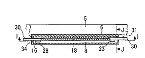
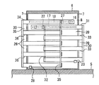
図6〜図10は、この発明の他の実施の形態の一例を示す図で、図6は乗降口の戸開状態を示す前述の図17相当図、図7は図6のI−I線断面図、図8は図6のJ−J線断面図、図9は図6における乗降口の戸閉状態を示す図6相当図、図10は図9のK−K線断面図である。図において、前述の図1〜図5と同符号は相当部分を示す。
【0028】
31は第一引き戸で、戸板32の反軌道2側の面に角管状の補強材33が設けられて長手が水平方向に配置され、上下方向に互いに離れた補強材33の相互間に反軌道2側の面に開口した複数の溝状凹所20が形成される。また、補強材33の反軌道2側によって凸条部21が形成される。また、上縁部に設けられた案内具22によって第一戸レール17に係合されて、下端が戸袋8に設けられた下部案内具23に係合される。そして、戸開時には戸袋8に収納され、戸閉動作して隔壁体6の一方の縁部から突出して、この一方の縁部に対応した乗降口7幅のほぼ1/2を閉じる。
【0029】
34は第二引き戸で、戸板35の軌道2側の面に角管状の補強材36が設けられて長手が水平方向に配置され、上下方向に互いに離れた補強材36の相互間に軌道2側の面に開口した複数の溝状凹所26が形成され、上縁部に設けられた案内具27によって第二戸レール18に係合されて、下端が戸袋8に設けられた下部案内具28に係合される。そして、戸開時には戸袋8に収納されて溝状凹所26内に第一引き戸31の凸条部21が遊嵌される。また、戸閉動作して隔壁体6の他方の縁部から突出し、この他方の縁部に対応した他の乗降口7幅のほぼ1/2を閉じる。
【0030】
30は第一引き戸31及び第二引き戸34の戸閉方向の端面に設けられたテープスイッチからなる障害物検出器で、第一引き戸31等の戸閉動作時に乗降口7に障害物があるときに、この障害物によって押圧されて動作する。そして、障害物検出器30の動作を介して異常時制御されて第一引き戸31等の戸閉動作の中止、強制反転戸開等の制御が行われる。
【0031】
上記のように構成された停車場用乗降口装置においても、車両1がプラットホーム5に発着しない時間帯では、隔壁体6の乗降口7は一方の隔壁体6に設けられた第一引き戸31及び他方の隔壁体6に設けられた第一引き戸31又は一方の隔壁体6に設けられた第二引き戸34及び他方の隔壁体6に設けられた第2引き戸34のそれぞれが戸閉位置に配置され、互いに対向した引き戸によって図9及び図10に示すように閉じられている。これにより、プラットホーム5の待ち客が車両1の軌道2側へ入ることが防止される。
【0032】
そして、車両1がプラットホーム5に到着すると、車両1の出入口3の車両ドア4の戸開動作と同期して、第一引き戸31及び第二引き戸34が戸開動作して隔壁体6の戸袋8に収納され、図6及び図7に示すように乗降口7が開放される。これによって、車両1の出入口3とプラットホーム5の乗降口7の間を乗客が乗降する。
【0033】
そして、第一引き戸31及び第二引き戸34の両者が戸開時に隔壁体6の戸袋8において重合状態に配置されて、第二引き戸25の溝状凹所26内に第一引き戸19の凸条部21が遊嵌される。また、上記両者の全開停止時において乗降口7の縁部側の端部が、乗降口7の縁部から突出した位置に配置される。したがって、詳細な説明を省略するが図6〜図10の実施の形態においても図1〜図5の実施の形態と同様な作用が得られる。
【0034】
【発明の効果】
この発明は以上説明したように、プラットホームの車両軌道に沿う縁部に互いに離れて立設され、壁面が車両軌道に沿う方向に配置されて相互間に乗降口を形成した隔壁体と、この隔壁体によって形成された戸袋に設けられた開閉機構と、長手が水平方向に配置されて一面に突出し上下方向に互いに離れて複数の凸条部が形成されて、開閉機構により水平方向に開閉動作し戸開時には戸袋に収納され、戸閉動作して隔壁体の一方の縁部から突出し、一方の縁部に対応した乗降口幅の一部を閉じる第一引き戸と、長手が水平方向に配置されて一面に開口し上下方向に互いに離れて複数の溝状凹所が形成されて、開閉機構により水平方向に開閉動作し戸開時には戸袋に収納され、溝状凹所に第一引き戸の凸条部が遊嵌され、戸閉動作して隔壁体の他方の縁部から突出し、他方の縁部に対応した他の乗降口幅の一部を閉じる第二引き戸とを設けたものである。
【0035】
これによって、車両がプラットホームに到着すると第一引き戸及び第二引き戸の両者が戸開動作し隔壁体の戸袋に収納されて乗降口が開放される。そして、上記両者が戸開時に隔壁体の戸袋に互いに重合状態に配置されて、第二引き戸の溝状凹所内に第一引き戸の凸条部が遊嵌される。このため、軌条の長手に直交した方向の隔壁体の奥行き寸法、すなわち隔壁体の厚さを薄くすることができる。したがって、プラットホーム幅が狭い停車場においても隔壁体を容易に設置することができて、車両がプラットホームにいないときにプラットホームの待ち客が車両の軌道側へ入ることを防ぐことができる。これにより、待ち客が車両の軌道側へ入ることによる不具合の発生を未然に防止する効果がある。
【0036】
また、この発明は以上説明したように、第一引き戸の凸条部を、第一引き戸を形成する戸板の反車両軌道側の面に設けられて長手が水平方向に配置された角管状の補強材によって形成し、第二引き戸の溝状凹所を、第二引き戸を形成する戸板の車両軌道側の面に設けられて長手が水平方向に配置された角管状の補強材の相互間によって形成したものである。
【0037】
これによって、第一引き戸及び第二引き戸が戸開時に隔壁体の戸袋において相互に重合状態に配置されて、第二引き戸の溝状凹所内に第一引き戸の凸条部が遊嵌される。このため、軌条の長手に直交した方向の隔壁体の奥行き寸法、すなわち隔壁体の厚さを薄くすることができる。したがって、プラットホーム幅が狭い停車場においても隔壁体を容易に設置することができて、車両がプラットホームにいないときにプラットホームの待ち客が車両の軌道側へ入ることを防ぐことができる。これにより、待ち客が車両の軌道側へ入ることによる不具合の発生を未然に防止する効果がある。
【0038】
また、この発明は以上説明したように、開閉機構は、第一引き戸に設けられた案内具が係合する第一戸レールと第二引き戸に設けられた案内具が係合する第二戸レールとを有し、第一戸レール及び第二戸レールを、隔壁体における戸袋の互いに対向した内面の一方によって支持したものである。
【0039】
これによって、軌条の長手に直交した方向の隔壁体の奥行き寸法、すなわち隔壁体の厚さを薄くすることができる。したがって、プラットホーム幅が狭い停車場においても隔壁体を容易に設置することができて、車両がプラットホームにいないときにプラットホームの待ち客が車両の軌道側へ入ることを防ぐことができる。これにより、待ち客が車両の軌道側へ入ることによる不具合の発生を未然に防止する効果がある。
【0040】
また、この発明は以上説明したように、第一引き戸及び第二引き戸の主要部を薄鋼板によって形成し、第一引き戸に設けられた案内具を、第一引き戸の凸条部の背面側に形成された溝状凹所内に装着し、第二引き戸に設けられた案内具を、第二引き戸の溝状凹所内に装着したものである。
【0041】
これによって、軌条の長手に直交した方向の隔壁体の奥行き寸法、すなわち隔壁体の厚さを薄くすることができる。したがって、プラットホーム幅が狭い停車場においても隔壁体を容易に設置することができて、車両がプラットホームにいないときにプラットホームの待ち客が車両の軌道側へ入ることを防ぐことができる。これにより、待ち客が車両の軌道側へ入ることによる不具合の発生を未然に防止する効果がある。
【図面の簡単な説明】
【図1】 この発明の実施の形態1を示す図で、乗降口の戸開状態を示す図であり後述する図17相当図。
【図2】 図1のF−F線断面図。
【図3】 図1のG−G線断面図。
【図4】 図1における乗降口の戸閉状態を示す図1相当図。
【図5】 図4のH−H線断面図。
【図6】 この発明の実施の形態2を示す図で、乗降口の戸開状態を示す図であり後述する図17相当図。
【図7】 図6のI−I線断面図。
【図8】 図6のJ−J線断面図。
【図9】 図6における乗降口の戸閉状態を示す図6相当図。
【図10】 図9のK−K線断面図。
【図11】 従来の停車場用乗降口装置を示す図で、車両の到着時状態を示すプラットホームの要部平面図。
【図12】 図11の矢印A部の拡大正面図。
【図13】 図12のB−B線断面図。
【図14】 図12のC−C線断面図。
【図15】 乗降口の戸開状態を示す図11相当図。
【図16】 図15の矢印D部の拡大正面図。
【図17】 図16のE−E線断面図。
【符号の説明】
1 車両、 2 軌道、 5 プラットホーム、 6 隔壁体、 7 乗降口、 8 戸袋、 16 開閉機構、 17 第一戸レール、 18 第二戸レール、 19 第一引き戸、 20 溝状凹所、 21 凸条部、 22 案内具、 25 第二引き戸、 26 溝状凹所、 27 案内具、 31 第一引き戸、 32 戸板、 33 補強材、 34 第二引き戸、 35 戸板、 36 補強材。[0001]
BACKGROUND OF THE INVENTION
The present invention relates to an entrance / exit device for a stop, in which partition walls are erected apart from each other at edges along a vehicle traveling path of a platform, and an entrance / exit is formed between these partition walls.
[0002]
[Prior art]
FIGS. 11 to 17 are views showing a conventional stopway entrance / exit device, FIG. 11 is a plan view of the main part of the platform showing the arrival state of the vehicle, and FIG. 12 is an enlarged front view of arrow A in FIG. 13 is a cross-sectional view taken along the line BB in FIG. 12, FIG. 14 is a cross-sectional view taken along the line CC in FIG. 12, FIG. 15 is a view corresponding to FIG. FIG. 17 is a cross-sectional view taken along line EE of FIG.
[0003]
In the figure, 1 is a vehicle traveling on a
[0004]
[0005]
A first sliding
[0006]
In the conventional stopway entrance / exit device configured as described above, the entrance /
[0007]
When the vehicle 1 arrives at the
[0008]
[Problems to be solved by the invention]
In the entrance / exit device for a stop as described above, the first sliding
[0009]
The present invention has been made in order to solve such a problem, and is provided with an entrance / exit device for a stop that can store a first sliding door and a second sliding door arranged in a superposed state when the door is opened in a partition wall having a shallow depth. The purpose is to obtain.
[0010]
[Means for Solving the Problems]
In the entrance / exit device for a stop according to the present invention, a partition wall body that is erected away from each other along an edge of the platform along the vehicle track and has wall surfaces arranged in a direction along the vehicle track to form an entrance / exit between them The opening / closing mechanism provided in the door pocket formed by the partition body and the longitudinal direction are arranged in the horizontal direction, projecting on one surface and separated from each other in the vertical direction to form a plurality of ridges, and the opening / closing mechanism in the horizontal direction A first sliding door that opens and closes and is stored in a door pocket when the door is opened, closes and projects from one edge of the bulkhead, and closes a part of the entrance / exit width corresponding to the one edge. Are opened in one plane and are separated from each other in the vertical direction, and a plurality of groove-shaped recesses are formed, opened and closed in the horizontal direction by the opening and closing mechanism, and stored in the door pocket when the door is opened, and the first sliding door in the groove-shaped recess The ridge part of the It protrudes, and a second sliding door to close a part of the other entrance width corresponding to the other edge portion is provided from the other edge portion of the partition wall body and.
[0011]
Moreover, in the boarding / alighting device for a stop according to the present invention, the convex strip portion of the first sliding door is provided on the surface on the side opposite to the vehicle track of the door plate forming the first sliding door, and the corner is arranged in the horizontal direction in the longitudinal direction. Each of the rectangular tubular reinforcements formed by a tubular reinforcing material, in which the grooved recess of the second sliding door is provided on the vehicle track side surface of the door plate forming the second sliding door, and the longitudinal direction is disposed in the horizontal direction. Formed between.
[0012]
Further, in the platform entrance / exit device according to the present invention, the opening / closing mechanism includes a first door rail engaged with a guide provided on the first sliding door and a guide provided on the second sliding door. and a Ninohe rail, first units rails and second units rail is supported from one of the inner surface of the opposing the door pocket in the partition wall member.
[0013]
Moreover, in the entrance / exit device for a stop according to the present invention, the first sliding door and the second sliding door are mainly formed of a thin steel plate, and the guide provided on the first sliding door is a ridge portion of the first sliding door. is mounting on the rear side of the formed groove-like recess, the guide member provided on the second sliding door is mounted in a groove shape in the recess of the second sliding door.
[0014]
DETAILED DESCRIPTION OF THE INVENTION
Embodiment 1 FIG.
1 to 5 are views showing an example of an embodiment of the present invention. FIG. 1 is a view corresponding to FIG. 17 showing the door opening state of the entrance and exit, and FIG. 2 is a cross-sectional view taken along the line FF of FIG. 3 is a cross-sectional view taken along line GG in FIG. 1, FIG. 4 is a view corresponding to FIG. 1 showing the door closing state of the entrance / exit in FIG. 1, and FIG. 5 is a cross-sectional view taken along line HH in FIG.
[0015]
In the figure, 1 is a vehicle traveling on a
[0016]
[0017]
[0018]
[0019]
[0020]
In the platform entrance / exit device configured as described above, the entrance /
[0021]
When the vehicle 1 arrives at the
[0022]
And both the
[0023]
Therefore, the
[0024]
Moreover, both the
[0025]
In addition, by installing the
[0026]
In addition, when the first sliding
[0027]
6 to 10 are diagrams showing an example of another embodiment of the present invention. FIG. 6 is a view corresponding to FIG. 17 showing the door opening state of the entrance and exit, and FIG. 7 is a line II in FIG. 8 is a cross-sectional view taken along line JJ of FIG. 6, FIG. 9 is a view corresponding to FIG. 6 showing the door closing state of the entrance / exit in FIG. 6, and FIG. 10 is a cross-sectional view taken along line KK of FIG. In the figure, the same reference numerals as those in FIGS.
[0028]
31 is a first sliding door, and a rectangular
[0029]
[0030]
30 is an obstacle detector comprising a tape switch provided on the end face of the first sliding
[0031]
Also in the platform entrance / exit device configured as described above, the entrance /
[0032]
When the vehicle 1 arrives at the
[0033]
And both the
[0034]
【The invention's effect】
As described above, the present invention provides a partition body that is provided separately from each other at the edges along the vehicle track of the platform, and whose wall surfaces are arranged in the direction along the vehicle track to form an entrance / exit, and the partition wall. The opening and closing mechanism provided in the door pocket formed by the body and the longitudinally arranged in the horizontal direction, projecting on one surface and separated from each other in the vertical direction to form a plurality of ridges, the opening and closing mechanism to open and close in the horizontal direction When the door is opened, it is stored in the door pocket, the door closes and protrudes from one edge of the partition wall, and the first sliding door closes a part of the entrance / exit width corresponding to the one edge, and the length is arranged in the horizontal direction. A plurality of groove-shaped recesses are formed on one surface and separated from each other in the vertical direction, and are opened and closed horizontally by an opening / closing mechanism and stored in a door pocket when the door is opened. The part is loosely fitted and the door closes and Protrudes from square edge is obtained by providing a second sliding door to close a part of the other entrance width corresponding to the other edge.
[0035]
As a result, when the vehicle arrives at the platform, both the first sliding door and the second sliding door are opened to be stored in the door pocket of the partition wall, and the entrance is opened. Then, both of the above are placed in a superposed state in the door pocket of the partition wall when the door is opened, and the ridge portion of the first sliding door is loosely fitted in the groove-like recess of the second sliding door. For this reason, the depth dimension of the partition body in the direction orthogonal to the length of the rail, that is, the thickness of the partition body can be reduced. Therefore, the partition wall can be easily installed even at a stop where the platform width is narrow, and it is possible to prevent a waiting user of the platform from entering the track side of the vehicle when the vehicle is not on the platform. As a result, there is an effect of preventing the occurrence of problems caused by waiting customers entering the track side of the vehicle.
[0036]
In addition, as described above, the present invention provides a rectangular tubular reinforcement in which the protruding strip portion of the first sliding door is provided on the surface on the side opposite to the vehicle track of the door plate forming the first sliding door and the longitudinal direction is arranged in the horizontal direction. The groove-like recess of the second sliding door is formed by a material between the rectangular tubular reinforcements provided on the vehicle track side surface of the door plate forming the second sliding door and arranged in the horizontal direction in the longitudinal direction. It is a thing.
[0037]
As a result, the first sliding door and the second sliding door are arranged in a superposed state in the door pocket of the partition body when the door is opened, and the convex strip portion of the first sliding door is loosely fitted in the groove-like recess of the second sliding door. For this reason, the depth dimension of the partition body in the direction orthogonal to the length of the rail, that is, the thickness of the partition body can be reduced. Therefore, the partition wall can be easily installed even at a stop where the platform width is narrow, and it is possible to prevent a waiting user of the platform from entering the track side of the vehicle when the vehicle is not on the platform. As a result, there is an effect of preventing the occurrence of problems caused by waiting customers entering the track side of the vehicle.
[0038]
In addition, as described above, the opening / closing mechanism of the present invention includes a first door rail that engages a guide provided on the first sliding door and a second door rail that engages a guide provided on the second sliding door. It has the door, in which the first units rails and second units rails, supported by one of the inner surface that face each other in the door pocket in the partition wall member.
[0039]
Thereby, the depth dimension of the partition body in the direction orthogonal to the length of the rail, that is, the thickness of the partition body can be reduced. Therefore, the partition wall can be easily installed even at a stop where the platform width is narrow, and it is possible to prevent a waiting user of the platform from entering the track side of the vehicle when the vehicle is not on the platform. As a result, there is an effect of preventing the occurrence of problems caused by waiting customers entering the track side of the vehicle.
[0040]
In addition, as described above, the main part of the first sliding door and the second sliding door is formed of a thin steel plate, and the guide provided on the first sliding door is placed on the back side of the protruding strip portion of the first sliding door. The guide is provided in the formed groove-like recess and provided in the second sliding door, and is installed in the groove-like recess of the second sliding door.
[0041]
Thereby, the depth dimension of the partition body in the direction orthogonal to the length of the rail, that is, the thickness of the partition body can be reduced. Therefore, the partition wall can be easily installed even at a stop where the platform width is narrow, and it is possible to prevent a waiting user of the platform from entering the track side of the vehicle when the vehicle is not on the platform. As a result, there is an effect of preventing the occurrence of problems caused by waiting customers entering the track side of the vehicle.
[Brief description of the drawings]
FIG. 1 is a diagram showing a first embodiment of the present invention, and is a diagram showing a door opening state of an entrance / exit, corresponding to FIG. 17 described later.
FIG. 2 is a cross-sectional view taken along line FF in FIG.
3 is a cross-sectional view taken along line GG in FIG.
4 is a view corresponding to FIG. 1, showing a door closing state of the entrance / exit in FIG. 1;
5 is a cross-sectional view taken along line HH in FIG. 4;
FIG. 6 is a diagram showing a second embodiment of the present invention, and is a diagram showing a door opening state of the entrance and exit, corresponding to FIG. 17 described later.
7 is a cross-sectional view taken along the line II of FIG.
8 is a cross-sectional view taken along line JJ in FIG.
9 is a view corresponding to FIG. 6 showing a door closing state of the entrance / exit in FIG. 6;
10 is a cross-sectional view taken along the line KK in FIG. 9;
FIG. 11 is a diagram showing a conventional stopway entrance / exit device, and is a plan view of the main part of the platform showing the arrival state of the vehicle.
12 is an enlarged front view of an arrow A part in FIG.
13 is a sectional view taken along line BB in FIG.
14 is a cross-sectional view taken along the line CC of FIG.
FIG. 15 is a view corresponding to FIG. 11 showing the door opening state of the entrance / exit.
16 is an enlarged front view of an arrow D part in FIG.
17 is a sectional view taken along line EE in FIG.
[Explanation of symbols]
DESCRIPTION OF SYMBOLS 1 Vehicle, 2 Tracks, 5 Platform, 6 Partition body, 7 Entrance / exit, 8 Door bag, 16 Opening / closing mechanism, 17 First door rail, 18 Second door rail, 19 First sliding door, 20 Groove-shaped recess, 21 Projection Part, 22 guide tool, 25 second sliding door, 26 grooved recess, 27 guide tool, 31 first sliding door, 32 door plate, 33 reinforcing material, 34 second sliding door, 35 door plate, 36 reinforcing material.
Claims (4)
上記第一引き戸に設けられた案内具を、上記第一引き戸の凸条部の背面側に形成された溝状凹所内に装着し、第二引き戸に設けられた案内具を、上記第二引き戸の溝状凹所内に装着したことを特徴とする請求項3に記載の停車場用乗降口装置。 As for the 1st sliding door and the 2nd sliding door, the principal part is formed with a thin steel plate,
The guide member provided in the first door, the first attached to the sliding door of the convex portion of the rear side in the formed groove-like recesses, the guide member provided on the second sliding door, the second door The stop device for a stop according to claim 3 , which is mounted in a groove-like recess.
Priority Applications (1)
| Application Number | Priority Date | Filing Date | Title |
|---|---|---|---|
| JP2000336817A JP4526687B2 (en) | 2000-11-06 | 2000-11-06 | Entrance / exit equipment for stop |
Applications Claiming Priority (1)
| Application Number | Priority Date | Filing Date | Title |
|---|---|---|---|
| JP2000336817A JP4526687B2 (en) | 2000-11-06 | 2000-11-06 | Entrance / exit equipment for stop |
Publications (3)
| Publication Number | Publication Date |
|---|---|
| JP2002145049A JP2002145049A (en) | 2002-05-22 |
| JP2002145049A5 JP2002145049A5 (en) | 2007-12-06 |
| JP4526687B2 true JP4526687B2 (en) | 2010-08-18 |
Family
ID=18812297
Family Applications (1)
| Application Number | Title | Priority Date | Filing Date |
|---|---|---|---|
| JP2000336817A Expired - Lifetime JP4526687B2 (en) | 2000-11-06 | 2000-11-06 | Entrance / exit equipment for stop |
Country Status (1)
| Country | Link |
|---|---|
| JP (1) | JP4526687B2 (en) |
Families Citing this family (5)
| Publication number | Priority date | Publication date | Assignee | Title |
|---|---|---|---|---|
| JP4599140B2 (en) * | 2004-02-17 | 2010-12-15 | 三菱重工業株式会社 | How to open and close the movable fence and movable fence |
| ITTO20070396A1 (en) * | 2007-06-06 | 2008-12-07 | Oclap Srl | ACCESS BARRIER FOR RAILWAY STATION BANKS |
| WO2012147225A1 (en) * | 2011-04-29 | 2012-11-01 | 三菱電機株式会社 | Platform door device |
| JP5828054B1 (en) * | 2015-04-08 | 2015-12-02 | 株式会社音楽館 | Platform entry / exit opening and closing device |
| RU2771395C1 (en) * | 2021-10-22 | 2022-05-04 | Валерий Иванович Паутов | Station platform sliding fence of the subway |
Citations (3)
| Publication number | Priority date | Publication date | Assignee | Title |
|---|---|---|---|---|
| JPH11334579A (en) * | 1998-05-22 | 1999-12-07 | Nabco Ltd | Movable fence for platform |
| JP2001191914A (en) * | 2000-01-12 | 2001-07-17 | Mitsubishi Electric Corp | Getting-on/off gateway device for station |
| JP2002029410A (en) * | 2000-07-14 | 2002-01-29 | Kyosan Electric Mfg Co Ltd | Door device |
-
2000
- 2000-11-06 JP JP2000336817A patent/JP4526687B2/en not_active Expired - Lifetime
Patent Citations (3)
| Publication number | Priority date | Publication date | Assignee | Title |
|---|---|---|---|---|
| JPH11334579A (en) * | 1998-05-22 | 1999-12-07 | Nabco Ltd | Movable fence for platform |
| JP2001191914A (en) * | 2000-01-12 | 2001-07-17 | Mitsubishi Electric Corp | Getting-on/off gateway device for station |
| JP2002029410A (en) * | 2000-07-14 | 2002-01-29 | Kyosan Electric Mfg Co Ltd | Door device |
Also Published As
| Publication number | Publication date |
|---|---|
| JP2002145049A (en) | 2002-05-22 |
Similar Documents
| Publication | Publication Date | Title |
|---|---|---|
| JP4141790B2 (en) | Movable home fence device | |
| JP4526687B2 (en) | Entrance / exit equipment for stop | |
| JP4397219B2 (en) | Flexible movable fence for different types of vehicles | |
| JP4169391B2 (en) | Platform movable fence | |
| JP2659488B2 (en) | Sliding door device | |
| JP6143897B1 (en) | elevator | |
| JP4397493B2 (en) | Entrance / exit equipment for stop | |
| JP4275830B2 (en) | Entrance / exit equipment for stop | |
| US4198785A (en) | Movable threshold door seal | |
| JP2002053034A (en) | Platform door device | |
| JP2000108889A (en) | Opening/closing fence for platform | |
| US908199A (en) | Car-end construction. | |
| CN110406556B (en) | Partition wall door of subway cab | |
| JP3024963B1 (en) | Platform protection fence device | |
| JP7321073B2 (en) | Platform door device | |
| JP2537299Y2 (en) | Elevator threshold | |
| US4176497A (en) | Sliding door and threshold arrangement for a railway passenger car compartment | |
| CN113966309B (en) | Elevator door | |
| JP2516802Y2 (en) | Lower guide device for sliding doors | |
| JPH0313505Y2 (en) | ||
| RU26039U1 (en) | DOOR OF Covered Freight Wagon | |
| KR100799341B1 (en) | Adaptive vertical type platform screen door | |
| JP4378156B2 (en) | Elevator door gap closing device | |
| KR200453386Y1 (en) | Anti-incoming apparatus of foreign matter for electric train doorway | |
| JPH07149485A (en) | Dam weighter |
Legal Events
| Date | Code | Title | Description |
|---|---|---|---|
| A521 | Written amendment |
Free format text: JAPANESE INTERMEDIATE CODE: A523 Effective date: 20071019 |
|
| A621 | Written request for application examination |
Free format text: JAPANESE INTERMEDIATE CODE: A621 Effective date: 20071019 |
|
| RD02 | Notification of acceptance of power of attorney |
Free format text: JAPANESE INTERMEDIATE CODE: A7422 Effective date: 20071019 |
|
| A977 | Report on retrieval |
Free format text: JAPANESE INTERMEDIATE CODE: A971007 Effective date: 20100128 |
|
| A131 | Notification of reasons for refusal |
Free format text: JAPANESE INTERMEDIATE CODE: A131 Effective date: 20100323 |
|
| A521 | Written amendment |
Free format text: JAPANESE INTERMEDIATE CODE: A523 Effective date: 20100415 |
|
| TRDD | Decision of grant or rejection written | ||
| A01 | Written decision to grant a patent or to grant a registration (utility model) |
Free format text: JAPANESE INTERMEDIATE CODE: A01 Effective date: 20100601 |
|
| A01 | Written decision to grant a patent or to grant a registration (utility model) |
Free format text: JAPANESE INTERMEDIATE CODE: A01 |
|
| A61 | First payment of annual fees (during grant procedure) |
Free format text: JAPANESE INTERMEDIATE CODE: A61 Effective date: 20100602 |
|
| FPAY | Renewal fee payment (event date is renewal date of database) |
Free format text: PAYMENT UNTIL: 20130611 Year of fee payment: 3 |
|
| R150 | Certificate of patent or registration of utility model |
Ref document number: 4526687 Country of ref document: JP Free format text: JAPANESE INTERMEDIATE CODE: R150 Free format text: JAPANESE INTERMEDIATE CODE: R150 |
|
| R250 | Receipt of annual fees |
Free format text: JAPANESE INTERMEDIATE CODE: R250 |
|
| R250 | Receipt of annual fees |
Free format text: JAPANESE INTERMEDIATE CODE: R250 |
|
| R250 | Receipt of annual fees |
Free format text: JAPANESE INTERMEDIATE CODE: R250 |
|
| R250 | Receipt of annual fees |
Free format text: JAPANESE INTERMEDIATE CODE: R250 |
|
| R250 | Receipt of annual fees |
Free format text: JAPANESE INTERMEDIATE CODE: R250 |
|
| EXPY | Cancellation because of completion of term |