JP4525401B2 - Imaging range adjustment device for camera entrance cordless handset - Google Patents
Imaging range adjustment device for camera entrance cordless handset Download PDFInfo
- Publication number
- JP4525401B2 JP4525401B2 JP2005079741A JP2005079741A JP4525401B2 JP 4525401 B2 JP4525401 B2 JP 4525401B2 JP 2005079741 A JP2005079741 A JP 2005079741A JP 2005079741 A JP2005079741 A JP 2005079741A JP 4525401 B2 JP4525401 B2 JP 4525401B2
- Authority
- JP
- Japan
- Prior art keywords
- camera
- lens
- imaging range
- cam
- guide
- Prior art date
- Legal status (The legal status is an assumption and is not a legal conclusion. Google has not performed a legal analysis and makes no representation as to the accuracy of the status listed.)
- Expired - Fee Related
Links
Images
Landscapes
- Closed-Circuit Television Systems (AREA)
- Studio Devices (AREA)
Description
本発明は、住宅用のインターホンの一種であるテレビドアホンシステム等におけるカメラ玄関子機に適用され、カメラの撮像範囲を変更調整するカメラ玄関子機の撮像範囲調整装置に関するものである。 The present invention relates to an imaging range adjustment device for a camera entrance unit that is applied to a camera entrance unit in a TV door phone system or the like, which is a kind of residential intercom, and changes and adjusts the imaging range of the camera.
一般に、住宅用のインターホンの一種であるテレビドアホンの構成機器であるカメラ玄関子機は塀や門柱等の所定の位置に設置される。 In general, a camera entrance cordless handset that is a component device of a television door phone, which is a kind of residential intercom, is installed at a predetermined position such as a fence or a gatepost.
そして、従来におけるカメラ玄関子機のカメラの角度調整装置は、カメラ本体が本体ケースに回転軸を支点に回動可能に取付けられ、このカメラ本体の回転軸に対して略直交する側部に従動部を設け、この従動部が摺動可能に嵌合する傾斜した長溝部を有する駆動用レバーを本体ケースに移動可能に設置し、駆動用レバーを移動させることにより、長溝部によってカメラ本体における従動部の設置側を上下動させてカメラ本体を回動支点を中心に回動させるように構成したものであり、この構成によって、任意の角度にカメラを設置するための角度調整作業をレバー移動により行うことができるようにしている(特許文献1参照)。
しかし、上記した従来のカメラ玄関子機のカメラの角度調整装置は、カメラ本体を回動させてカメラの角度を変更調整するものであり、バンダルプルーフ対応のためにピンホールレンズを使用したカメラ玄関子機には適用できないものである。すなわち、このピンホールレンズを使用したカメラ玄関子機においては、映像光を取り入れる開口部が小さいことと、この開口部と所定の位置関係を必要とするピンホールレンズが固定されるために、カメラ本体を回動させることが困難であるためである。 However, the camera angle adjustment device of the conventional camera entrance slave unit described above is to change and adjust the angle of the camera by rotating the camera body, and the camera entrance using a pinhole lens for vandal proof correspondence. It cannot be applied to the handset. That is, in a camera entrance cordless handset using this pinhole lens, since the opening for taking image light is small and the pinhole lens that requires a predetermined positional relationship with this opening is fixed, This is because it is difficult to rotate the main body.
本発明は、上記した問題点を解決するものであり、その目的とするところは、カメラレンズを固定した状態で撮像素子を移動させることで、カメラの撮像範囲を変更することができ、バンダルプルーフ対応のためにピンホールレンズを使用したカメラ玄関子機に適用できるカメラ玄関子機の撮像範囲調整装置を提供することにある。 The present invention solves the above-described problems, and an object of the present invention is to change the imaging range of the camera by moving the imaging element while the camera lens is fixed. An object of the present invention is to provide an imaging range adjusting device for a camera entrance device that can be applied to a camera entrance device using a pinhole lens.
上記の目的を達成するために、本発明に係るカメラ玄関子機の撮像範囲調整装置は、撮像素子を移動することによりカメラの撮像範囲を変更調整するカメラ玄関子機の撮像範囲調整装置であって、撮像素子を実装した回路基板を坦持し且つその移動方向に垂直な方向に対して傾斜したカムを有する可動部と、可動部を移動可能に保持すると共に、撮像素子に対向するカメラレンズを固定保持し且つ垂直方向に沿うスライドガイドを有する固定部と、スライドガイドを貫通してカムに摺接するカム用突起部を有し且つ固定部に移動可能に設けられた調整レバーを備え、調整レバーを移動させることにより、カム用突起部をスライドガイドに沿って移動させてカム用突起部をカムに摺動させ、当該カムの傾斜によって可動部を移動させて撮像素子を移動させるようにしたことを特徴とする。 In order to achieve the above object, an imaging range adjusting device for a camera entrance device according to the present invention is an imaging range adjusting device for a camera entrance device that changes and adjusts the imaging range of a camera by moving an imaging element. A movable part having a cam that carries a circuit board on which the imaging element is mounted and that is inclined with respect to a direction perpendicular to the moving direction, and a camera lens that holds the movable part movably and faces the imaging element A fixed portion having a slide guide along the vertical direction and an adjustment lever provided with a cam projection that passes through the slide guide and slidably contacts the cam and is movably provided on the fixed portion. By moving the lever, the cam projection is moved along the slide guide, the cam projection is slid on the cam, and the movable portion is moved by the inclination of the cam. Characterized in that so as to move to.
かかる構成により、調整レバーを移動させることにより、カム用突起部をスライドガイドに沿って移動させてカム用突起部をカムに摺動させ、当該カムの傾斜によって、可動部を調整レバーの移動方向に対して垂直方向に移動させることで、カメラレンズを固定した状態で撮像素子を移動させることができて、カメラの撮像範囲を変更することができる。この場合、調整レバーを、例えば、上下に移動することにより撮像素子を左右に移動できるために、左右の撮像範囲を広くすることができる。したがって、例えば、カメラレンズに、映像光を取り入れる狭小な開口部に対応するピンホールレンズを用いることで、バンダルプルーフ対応のためにピンホールレンズを使用したカメラ玄関子機に適用できるようになる。 With this configuration, by moving the adjustment lever, the cam projection is moved along the slide guide, the cam projection is slid on the cam, and the movable portion is moved in the moving direction of the adjustment lever by the inclination of the cam. By moving in the vertical direction, the imaging element can be moved with the camera lens fixed, and the imaging range of the camera can be changed. In this case, since the imaging element can be moved left and right by moving the adjustment lever up and down, for example, the left and right imaging ranges can be widened. Therefore, for example, by using a pinhole lens corresponding to a narrow opening for taking image light as a camera lens, the camera lens can be applied to a camera entrance device using a pinhole lens in order to cope with vandal proof.
また、本発明に係るカメラ玄関子機の撮像範囲調整装置は、上記した本発明に係るカメラ玄関子機の撮像範囲調整装置において、固定部は、ベース側フレーム部と、スライドガイドを有すると共に、カメラレンズを坦持したレンズ坦持側フレーム部と、可動部を移動可能に保持する保持手段を有していて、ベース側フレーム部にレンズ坦持側フレーム部を重ね合わせることで内部に収容空間と調整レバー保持ガイド部を形成し、収容空間に可動部を収容して記保持手段で保持すると共に、調整レバー保持ガイド部で調整レバーを移動可能に保持するようにしたことを特徴とする。 Further, the imaging range adjusting device of the camera entrance device according to the present invention is the imaging range adjusting device of the camera entrance device according to the present invention described above, the fixing unit has a base side frame portion and a slide guide, It has a lens-carrying-side frame part that carries the camera lens, and a holding means that holds the movable part in a movable manner, and the accommodation space is built inside by overlapping the lens-carrying-side frame part on the base-side frame part. The adjustment lever holding guide portion is formed, the movable portion is accommodated in the accommodation space and held by the holding means, and the adjustment lever is movably held by the adjustment lever holding guide portion.
かかる構成により、調整レバーを移動させることにより、収容空間内で可動部を移動させることで、カメラレンズを固定した状態で撮像素子を移動させることができて、カメラの撮像範囲を変更することができる。この場合、調整レバーを、例えば、上下に移動することにより撮像素子を左右に移動できるために、左右の撮像範囲を広くすることができる。したがって、例えば、カメラレンズに、映像光を取り入れる狭小な開口部に対応するピンホールレンズを用いることで、バンダルプルーフ対応のためにピンホールレンズを使用したカメラ玄関子機に適用できるようになる。 With such a configuration, by moving the adjustment lever and moving the movable part in the accommodation space, the imaging element can be moved with the camera lens fixed, and the imaging range of the camera can be changed. it can. In this case, since the imaging element can be moved left and right by moving the adjustment lever up and down, for example, the left and right imaging ranges can be widened. Therefore, for example, by using a pinhole lens corresponding to a narrow opening for taking image light as a camera lens, the camera lens can be applied to a camera entrance device using a pinhole lens in order to cope with vandal proof.
また、本発明に係るカメラ玄関子機の撮像範囲調整装置は、上記した本発明に係るカメラ玄関子機の撮像範囲調整装置において、保持手段は、ベース側フレーム部に設けられて可動部に摺接する複数の突起部と、レンズ坦持側フレーム部に設けられて可動部の移動方向に長いガイド孔部と、可動部に設けられてガイド孔部に摺動可能に挿入されるガイド用突起部とで構成してあることを特徴とする。 Further, the imaging range adjusting device for a camera entrance device according to the present invention is the imaging range adjusting device for a camera entrance device according to the present invention described above, wherein the holding means is provided on the base side frame portion and slides on the movable portion. A plurality of contacting projections, a guide hole provided in the lens-carrying-side frame portion and extending in the moving direction of the movable portion, and a guide projection provided in the movable portion and slidably inserted into the guide hole portion It is comprised by these.
かかる構成により、調整レバーを移動することにより、回路基板を坦持した可動部は、ベースフレーム部側の複数の突起部に摺接してその姿勢が規正されると共に、そのガイド孔部とガイド用突起部とにより、例えば、左右に水平に案内されて移動することができ、撮像素子を左右に水平移動することができて、左右の撮像範囲を広くすることができる。したがって、例えば、カメラレンズに、映像光を取り入れるために子機に設けた窓部に対応するピンホールレンズを用いることで、バンダルプルーフ対応のためにピンホールレンズを使用したカメラ玄関子機に適用できるようになる。 With this configuration, by moving the adjustment lever, the movable part carrying the circuit board is slidably brought into contact with the plurality of protrusions on the base frame part side, and its posture is regulated, and the guide hole part and the guide part are guided. For example, the protrusion can move while being guided horizontally to the left and right, the image sensor can be moved horizontally to the left and right, and the left and right imaging range can be widened. Therefore, for example, by using a pinhole lens corresponding to the window provided in the slave unit for taking image light in the camera lens, it can be applied to a camera entrance slave unit that uses a pinhole lens for vandal proof correspondence. become able to.
また、本発明に係るカメラ玄関子機の撮像範囲調整装置は、上記した本発明に係るカメラ玄関子機の撮像範囲調整装置において、カメラレンズが、映像光を取り入れるために子機ケースに設けた窓部に対応するピンホールレンズであることを特徴とする。 In addition, the imaging range adjusting device of the camera entrance device according to the present invention is the imaging range adjustment device of the camera entrance device according to the present invention described above, wherein the camera lens is provided in the slave device case for taking in image light. It is a pinhole lens corresponding to a window part.
かかる構成により、バンダルプルーフ対応のために、映像光を取り入れる窓部に対応するピンホールレンズを使用したカメラ玄関子機に適用できる撮像範囲調整装置が提供できるようになる。 With such a configuration, it is possible to provide an imaging range adjustment device that can be applied to a camera entrance device that uses a pinhole lens corresponding to a window portion into which image light is taken in in order to support vandal proof.
また、本発明に係るカメラ玄関子機の撮像範囲調整装置は、子機ケースに、子機ケースを設置箇所に取付けるための取付ボルトの挿入孔を設け、挿入孔に、前面部が窓部と同形状のボルトカバーを着脱可能に取付け、子機ケースにダミーピンホールを設けたことを特徴とする。 In addition, the imaging range adjusting device of the camera entrance child device according to the present invention is provided with an insertion hole for a mounting bolt for attaching the child device case to an installation location in the child device case, and the front portion is provided with a window portion in the insertion hole. A bolt cover of the same shape is detachably attached, and a dummy pin hole is provided in the slave unit case.
かかる構成により、ボルトカバーの前面部が窓部に同じ形状をしているために、逆に、窓部を、ボルトカバーと同様に取付ボルトを挿入したものと人に認識させて、子機ケースに設けたダミーピンホールが本当のピンホールであると誤認させる。したがって、悪戯でピンホールが潰される場合、ダミーピンホールが潰され、開口部内方にある本当のピンホールが潰されずにすむために、カメラ玄関子機は悪戯に対して強く、カメラ玄関子機は常に正常状態を維持することができる。 With this configuration, the front part of the bolt cover has the same shape as the window part. On the contrary, the window part is made to recognize that the installation bolt is inserted in the same manner as the bolt cover. The dummy pinhole provided in is misunderstood as a real pinhole. Therefore, when the pinhole is crushed due to mischief, the dummy pinhole is crushed and the real pinhole inside the opening is not crushed. The normal state can always be maintained.
本発明に係るカメラ玄関子機の撮像範囲調整装置調整によれば、カメラレンズを固定した状態で撮像素子を移動させることができて、カメラの撮像範囲を変更することができる。この場合、調整レバーを、例えば、上下に移動することにより撮像素子を左右に移動できるために、左右の撮像範囲を広くすることができる。したがって、例えば、カメラレンズに、映像光を取り入れる狭小な開口部に対応するピンホールレンズを用いることで、バンダルプルーフ対応のためにピンホールレンズを使用したカメラ玄関子機に適用できるようになる。 According to the imaging range adjustment device adjustment of the camera entrance cordless handset according to the present invention, the imaging element can be moved with the camera lens fixed, and the imaging range of the camera can be changed. In this case, since the imaging element can be moved left and right by moving the adjustment lever up and down, for example, the left and right imaging ranges can be widened. Therefore, for example, by using a pinhole lens corresponding to a narrow opening for taking image light as a camera lens, the camera lens can be applied to a camera entrance device using a pinhole lens in order to cope with vandal proof.
以下、本発明に係るカメラ玄関子機の撮像範囲調整装置の実施形態について、図面を参照しながら説明する。 Hereinafter, an embodiment of an imaging range adjustment device for a camera entrance slave according to the present invention will be described with reference to the drawings.
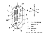
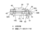
図1及び図2は本発明に係る撮像範囲調整装置を備えたカメラ玄関子機の説明図であり、図3は同カメラ玄関子機の取付説明のための斜視図、図4は同カメラ玄関子機を取付ける状態の説明図、図5は同カメラ玄関子機を取付ける調整レバー部分の説明図、図6は同カメラ玄関子機の子機ケースに設けたボルトカバー螺合孔を兼ねた取付ボルトの挿入孔にボルトカバーを螺合する状態の斜視図、図7は本発明に係るカメラ玄関子機の撮像範囲調整装置の前面(表側)から見た斜視図、図8は同撮像範囲調整装置の後面(裏側)から見た斜視図、図9は同撮像範囲調整装置の前面図、図7は同撮像範囲調整装置の後面図である。なお、説明の便宜上、前後、左右及び上下方向を図に示すように設定する。 1 and 2 are explanatory views of a camera entrance child device provided with an imaging range adjusting device according to the present invention. FIG. 3 is a perspective view for explaining the installation of the camera entrance child device. FIG. FIG. 5 is an explanatory view of an adjustment lever portion for mounting the camera entrance slave unit, and FIG. 6 is an installation that also serves as a bolt cover screwing hole provided in a slave unit case of the camera entrance slave unit. 7 is a perspective view of a state in which a bolt cover is screwed into a bolt insertion hole, FIG. 7 is a perspective view seen from the front (front side) of the imaging range adjusting device of the camera entrance device according to the present invention, and FIG. FIG. 9 is a front view of the imaging range adjustment device, and FIG. 7 is a rear view of the imaging range adjustment device. For convenience of explanation, front and rear, left and right, and up and down directions are set as shown in the figure.
図1に示すように、カメラ玄関子機Fは子機ケース1を備えており、この子機ケース1の表面部には、その上部から下部にかけて狭小な開口部である窓部2と、マイクロホン用スリット3、4と、コール釦5と、スピーカ用スリット6と、ボルトカバー螺合孔を兼ねる取付ボルトの挿入孔7とが設けてある。また、子機ケース1の表面部にはマイクロホン用スリット3の下方に位置させてダミーピンホール34Fが設けてあり、子機ケース1の下端部には排水孔9が設けてある。
As shown in FIG. 1, the camera entrance handset F includes a
上記したカメラ玄関子機Fは、取付金具60を介してカメラ玄関子機設置箇所61に取付けられるものであり(図4参照)、取付金具60は、図3に示すように、その上下に取付用穴部62を有しており、また、その上端部に係合突起部63が突設してあり、また、その下端部に取付ねじ座部64が設けてある。
The above-mentioned camera entrance cordless handset F is attached to the camera entrance cordless
そして、取付金具60は、図4に示すように、その上下に取付用穴部62を用いて取付ねじ66によりカメラ玄関子機設置箇所61に取付けられる。そして、図5に示すように、カメラ玄関子機Fは、その係合孔部57を係合突起部63に係脱可能に係合して取付け金具60に掛けられており、図4に示すように、子機ケース1に設けた挿入孔7に挿入した取付ボルト66を貫通孔を経て取付け金具60の取付ねじ座部64のねじ孔64aに螺合することでカメラ玄関子機Fは取付け金具60に取付けられる。
As shown in FIG. 4, the
そして、図6に示すように、挿入孔7には、前面部(正面部)8aが窓部2と同形状をしているボルトカバー8が螺合してある。すなわち、ボルトカバー8の前面部8aには、その中央に孔部8Aが形成してあって、この孔部8Aを挟んだ両側に係合凹部8Bが形成してある。また、ボルト回転工具67の先端面67aには係合突起部68が突設してある。そして、この係合突起部68を係合凹部8Bを係合させた状態で、ボルト回転工具67を回転させることで、ボルトカバー8を回転し挿入孔7に螺合する。
As shown in FIG. 6, a
上記したようにボルトカバー8の前面部8aが窓部2と同形状をしているために、逆に、窓部2を、ボルトカバー8と同様に取付ボルト66を挿入したものと人に認識させて、子機ケース1に設けたダミーピンホール34Fが本当のピンホールであると誤認させる。したがって、悪戯でピンホールが潰される場合、ダミーピンホール34Fが潰され、窓部2の奥にある本当のピンホール34A(後述の図7に示す)が潰されずにすむために、カメラ玄関子機Fは常に正常状態を維持する。
As described above, since the
そして、窓部2は、後述する撮像素子43の最大移動位置においてピンホールレンズ34を介して映像を結像できる大きさで開口しているし、また、窓部2は、光を透過する透明部材2Aで覆われていて、外部からの水滴や粉塵が窓部2から子機ケース1内に侵入するのを防止している。
The
そして、子機ケース1内には、ピンホールレンズカメラP(図23参照)と、このピンホールレンズカメラPの撮像範囲調整装置A(図7参照)と、マイクロホン(図示せず)と、スピーカ(図示せず)と、これらの機器の制御用回路基板(図示せず)とが収容してある。そして、図2に示すように、子機ケース1の裏側は裏蓋1Aで閉塞してあり、この裏蓋1Aには、その上部左側に撮像範囲調整用の調整レバー用孔部56が設けてある。そして、後述する撮像範囲調整装置Aの調整レバー50の連結軸部52が調整レバー用孔部56に挿通させてあって、調整レバー50のレバー部51が裏蓋1Aの外に表出している。
And in the subunit | mobile_unit
撮像範囲調整装置Aにより撮像範囲の調整を行なう際には、ボルト回転工具67でボルトカバー8を逆回転して、このボルトカバー8を挿入孔7から外し、更に、ボルト回転工具67で取付ボルト66を逆回転して外し、カメラ玄関子機Fを持ち上げることで係合突起部68と係合凹部8Bとの係合を解除し、カメラ玄関子機Fを裏返えす。
When the imaging range is adjusted by the imaging range adjusting device A, the
なお、ボルトカバー8のねじ部分が破壊されてボルトカバー8が上記した回転工具67では回転できなくなった場合には、マイナス(−)形状のドライバー(図示せず)を用いて、ボルトカバー8の前面部8aを打つことで、マイナス(−)形状の溝部(図示せず)を形成し、この溝部にドライバー先端を挿入して回転させるようにする。
In addition, when the screw part of the
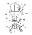
本発明に係るカメラ玄関子機の撮像範囲調整装置Aは、図7乃至図11に示すように、固定部10と可動部40と調整レバー50を備えており、固定部10は、ベース側フレーム部11と、レンズ坦持側フレーム部12と、可動部40を移動可能に保持する後述する保持手段を有している。
As shown in FIGS. 7 to 11, the imaging range adjustment device A for a camera entrance slave according to the present invention includes a fixed
図12及び図13に示すように、ベース側フレーム部11は板状のフレーム本体11Aを有しており、このフレーム本体11Aには、その左側部に位置させてベース側スライドガイド部13が形成してあり、このスライドガイド部13には、上下方向に長い長孔状のスライドガイド14が形成してあり、このスライドガイド14の上端側はフレーム本体11Aの左方に導入部14aを介して開放してある。
As shown in FIGS. 12 and 13, the base-
また、フレーム本体11Aの内面部(前面部)11aには、その左側下部に位置させて位置決め用突起部15が形成してある。そして、フレーム本体11Aの内面部11aには、その上部の左右に位置させてピン状の突起部16A、16Bが、下部の左に位置させてピン状の突起部16Cがそれぞれ突設してある。また、フレーム本体11Aには、その左側部に上下に位置させて取付孔17A、17Bが設けてあり、また、その右側下部に位置させて取付孔17Cが設けてある。
A
レンズ坦持側フレーム部12は、図14乃至図18に示すように、逆U字形状のフレーム本体12Aを有しており、このフレーム本体12Aの中央部には円形状のレンズ装着部20が設けてあり、このレンズ装着部20は、フレーム本体12Aに形成した筒部21の内周面に雌ねじ部22を形成して構成してある。
As shown in FIGS. 14 to 18, the lens-carrying-
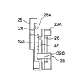
また、フレーム本体12Aには、レンズ装着部20を挟んだ左右に位置させて左右方向に長いガイド孔部23A、23Bが形成してある。また、フレーム本体12Aの左部にはレンズ坦持側スライドガイド部25が設けてある。そして、図17及び図18に示すように、フレーム本体12Aの内面部12aとレンズ坦持側スライドガイド部25との間には段差部26が形成してあって、この段差部26に上下方向に長い開口部27が形成してある。
The frame
また、レンズ坦持側スライドガイド部25は、図16に示すように、上下方向に沿うガイド面部28の左側に、このガイド面部28に対して垂直な立壁部28Aを上下方向に形成して構成してあり、このレンズ坦持側スライドガイド部25は断面L字形状を成している。そして、ガイド面部28には上下方向に長い長孔であるスライドガイド29が形成してあり、ガイド面部28の下部には、図16に示すようにL字形状の立壁部30が形成してあって、この立壁部30の内方が相手ケース位置決め部31にしてある。
Further, as shown in FIG. 16, the lens-carrying side
また、フレーム本体12Aの内面部12aには、レンズ坦持側スライドガイド部25の上端部に位置させて取付用ボス部32Aが突設してあり、また、レンズ坦持側スライドガイド部25の左下部に位置させて取付用ボス部32Bが突設してあり、また、フレーム本体12Aの右下部に位置させて取付用ボス部32Cが突設してある。また、フレーム本体12Aの左、右側の下部には、取付孔33aを有する取付座部33が設けてある。
Further, a mounting
そして、図14及び図15に示すように、レンズ装着部20には、カメラレンズであるピンホールレンズ34を保持したレンズ保持体35が、その周部に設けた雄ねじ部36を雌ねじ部22に螺合することで装着してある。そして、レンズ保持体35の中央にはピンホールレンズ34に対向するピンホール34Aが形成してある。
As shown in FIGS. 14 and 15, the
また、可動部40は、図19及び図20に示すように、基板保持プレート41と、この基板保持プレート41に保持された回路基板42を備えており、この回路基板42には、その表面の略中央部に撮像素子(CCD)43が実装してある。基板保持プレート41の中央部には窓部43Aが設けてあり、この窓部43Aの上、下縁部には押え部44が設けてあり、これらの押え部44が撮像素子43の表面を保護する透明ガラスから成る保護板45を押えている。
Further, as shown in FIGS. 19 and 20, the
また、基板保持プレート41には、その窓部43の左、右方に位置させてガイド突起部46A、46Bが突設してある。また、基板保持プレート41は、その左側下部にカム形成部47を設けており、このカム形成部47には上下方向に沿う長孔状のカム48が形成してある。このカム48は、その上端部48aに対して下端部48bを基板保持プレート41の中心側に寄せた傾斜孔である。
The
また、調整レバー50は、図21及び図22に示すように、レバー部51を有しており、このレバー部51には、このレバー部51の面部に対して直角に連結軸部52が形成してあり、この連結軸部52の端部にはスライダー53が設けてあり、このスライダー53にはカム用突起部54が突設してある。
Further, as shown in FIGS. 21 and 22, the
そして、図7乃至図11に示すように、レンズ坦持側フレーム部12がベース側フレーム部11に固着されていて固定部10が構成してある。この場合、図8に示すように、ベース側フレーム部11の位置決め用突起部16をレンズ坦持側フレーム部12の相手ケース位置決め部31に嵌合し、取付用ボス部32Aを取付孔17Aに、取付用ボス部32Bを取付孔17Bに、更に、取付用ボス部32Cを取付孔17Cにそれぞれ一致させて取付ねじ55により固着してある。
As shown in FIGS. 7 to 11, the lens-carrying-
この場合、図11に示すように、ベース側フレーム部11とレンズ坦持側フレーム部12との間には収容空間Kと調整レバー保持ガイド部Mが形成される。この調整レバー保持ガイド部Mは、互いに対向するベース側スライドガイド部13とレンズ坦持側スライドガイド部25との間の空間であり、図12に示すベース側スライドガイド部13と図14及び図15に示すレンズ坦持側スライドガイド部25との対向により、図12に示すスライドガイド14と図16に示すスライドガイド29が図9に示す状態において互いに対向するようになる。
In this case, as shown in FIG. 11, an accommodation space K and an adjustment lever holding guide portion M are formed between the base
そして、収容空間Kには図9に示す可動部40が収容してある。この場合、図11に示すように、ベース側フレーム部11に設けた複数の突起部16A、16B、16Cが可動部40の回路基板42の面部に摺接しており、また、図9に示すように、可動部40における左、右のガイド突起部46A、46Bがレンズ坦持側フレーム部12の左右のガイド孔部23A、23Bに摺動可能に挿入してあり、また、図17及び図18に示すように、可動部40のカム形成部42が図17および図18に示す開口部27に挿入してあって、可動部40が左右方向に移動可能にしてある。そして、レンズ坦持側スライドガイド部25の前面に図19及び図20に示すカム形成部42が位置しており、このカム形成部42に形成した長孔状のカム48が図9に示すようにスライドガイド14、29に重なり合うようになる。
And the
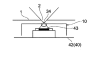
このように、可動部40が収容空間Kに収容された状態では、ピンホールレンズ34の後方に撮像素子43が位置している。また、上記した保持手段は、ベース側フレーム部11は設けられて可動部40に摺接する複数の突起部16A、16B、16Cと、レンズ坦持側フレーム部12に設けられて可動部40の移動方向(左右方向)に長いガイド孔部23A、23Bと、可動部40に設けられてガイド孔部23A、23Bに摺動可能に挿入されるガイド用突起部46A、46Bとで構成してある。
Thus, in a state where the
また、調整レバー保持ガイド部Mには、操作レバー50のスライダー53が挿入してあって、このスライダー53がスライドガイド部26のガイド面部27と立壁部28とに摺接していて、図9に示すように、このスライダー53に突設したカム用突起部54がスライドガイド29を貫通してカム48に挿入してある。また、操作レバー50の連結軸部52がベース側フレーム部11のスライドガイド14を貫通していて、操作レバー50のレバー部51がベース側フレーム部11の後方に配置されている。
In addition, the
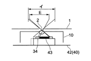
そして、上記のように構成されたカメラ玄関子機の撮像範囲調整装置Aは、その取付座部33を用いて子機ケース1の内部にねじで固定されていて、ピンホールレンズ34がピンホール34Aを介して窓部2に接近させてある。そして、図23に示すように、窓部2とピンホール34Aとピンホールレンズ34と上記した撮像素子43とでピンホールレンズカメラPを構成してある。また、図2に示すように、調整レバー50は、その連結軸部52を裏蓋9の調整レバー用孔部56に挿入した状態で、レバー部51を外に表出させ、連結軸部52を摘み部として調整レバー用孔部56から突出させている。
And the imaging range adjustment apparatus A of the camera entrance child machine comprised as mentioned above is being fixed with the screw inside the
ピンホールレンズ34の撮像範囲と撮像素子43の位置との関係を図24に示す。この図中イで示す円内がピンホールレンズ34の撮像可能範囲であり、ロは右側撮像時の撮像素子43の位置であり、ハは左側撮像時の撮像素子43の位置である。また、撮像素子43が右に移動した場合のピンホールレンズ34の撮像範囲Eと撮像可能範囲イは図25に表すようになるし、撮像素子43が左に移動した場合のピンホールレンズ34の撮像範囲Eと撮像可能範囲イは図26に表すようになる。
The relationship between the imaging range of the
次に、上記のように構成された本発明に係るカメラ玄関子機の撮像範囲調整装置Aの作動を説明する。 Next, the operation of the imaging range adjusting apparatus A for the camera entrance slave according to the present invention configured as described above will be described.
図27に示すように、調整レバー50が中立位置(標準位置)にある場合、ピンホールレンズ34の中心aと撮像素子43の中心bがピンホールレンズカメラPの中心線d上に位置しており、ピンホールレンズ34と撮像素子43の位置関係が同位置にあり、ピンホールレンズカメラPの撮像範囲Eは図28に示すようになり、ピンホールレンズ34の正面を撮像するようになる。
As shown in FIG. 27, when the
また、図29に示すように、調整レバー50を下方に移動させると、スライダー53がレンズ坦持側スライドガイド部25のガイド面部27と立壁部28とに摺動していて、カム用突起部54がカム48を下方向に向って摺動する。このために、カム用突起部54がカム48を介して可動部40を図29において右方向に移動させる。この移動は、可動部40の左、右のガイド突起部46A、46Bがレンズ坦持側フレーム部12の左右のガイド孔部23A、23B内を摺動することで行なわれる。
Further, as shown in FIG. 29, when the
このように、可動部40が右方向に移動ことにより、撮像素子43の中心bがピンホールレンズカメラPの中心線dから右にずれ、ピンホールレンズ34の撮像範囲Eは図30に示すようになり、ピンホールレンズカメラPは、ピンホールレンズ34の左側を撮像するようになる。
Thus, when the
また、図31に示すように、調整レバー50を上方に移動させると、スライダー53がレンズ坦持側スライドガイド部25のガイド面部27と立壁部28とに摺動していて、カム用突起部54がカム48を上方向に向って摺動する。このために、カム用突起部54がカム48を介して可動部40を左方向に移動させる。この移動は、可動部40の左、右のガイド突起部46A、46Bがレンズ坦持側フレーム部12の左右のガイド孔部23A、23B内を摺動することで行なわれる。
As shown in FIG. 31, when the
このように、可動部40が左方向に移動することにより、図32に示すように撮像素子43の中心bがピンホールレンズカメラPの中心線dから左にずれ、ピンホールレンズカメラPの撮像範囲得は図32に示すようになり、ピンホールレンズカメラPは、ピンホールレンズ34の右側を撮像するようになる。
Thus, when the
上記した本発明の実施の形態によれば、調整レバー50を移動させることにより、カム用突起部54をスライドガイド29に沿って移動させてカム用突起部54をカム48に摺動させ、当該カム48の傾斜によって、可動部40を調整レバー50の移動方向(左右方向)に対して垂直方向(上下方向)に移動させることで、ピンホールレンズ34を固定した状態で撮像素子43を移動させることができて、ピンホールレンズカメラPの撮像範囲を変更することができる。この場合、調整レバー50を上下に移動することにより撮像素子43を左右に移動できるために、左右の撮像範囲を広くすることができる。したがって、バンダルプルーフ対応のためにピンホールレンズを使用したカメラ玄関子機に適用できるようになる。
According to the above-described embodiment of the present invention, by moving the
また、本発明の実施の形態によれば、保持手段は、ベース側フレーム部11は設けられて可動部40に摺接する複数の突起部16A、16B、16Cと、レンズ坦持側フレーム部12に設けられて可動部40の移動方向に長いガイド孔部23A、23Bと、可動部40に設けられてガイド孔部23A、23Bに摺動可能に挿入されるガイド用突起部46A、46Bとで構成してあることにより、調整レバー50を移動することにより、可動部40は複数の突起部16A、16B、16Cに摺接してその姿勢を規正されると共に、ガイド孔部23A、23Bとガイド用突起部46A、46Bとにより、左右に水平に案内されて移動することができ、撮像素子43を左右に水平移動することができる。
Further, according to the embodiment of the present invention, the holding means includes the plurality of
また、本発明の実施の形態によれば、ボルトカバー8の前面部8aが窓部2に同じ形状をしているために、逆に、窓部2が、ボルトカバー8と同様に取付ボルト66を挿入したものと人に認識させて、子機ケース1に設けたダミーピンホール34Fが本当のピンホールであると誤認させる。したがって、いたずらで、ピンホールが潰される場合、ダミーピンホール34Fが潰され、窓部2の奥にある本当のピンホール34が潰されずにすむために、カメラ玄関子機Fはいたずらに対して強く、カメラ玄関子機Fは常に正常状態を維持することができる。
Further, according to the embodiment of the present invention, since the
なお、各部材の形状等は上記した実施の形態にて説明したもののみに限定されず、仕様等によって適当に変更される。 The shape and the like of each member are not limited to those described in the above-described embodiments, and can be appropriately changed depending on the specifications and the like.
本発明に係るカメラ玄関子機の撮像範囲調整装置によれば、カメラレンズを固定した状態で撮像素子を移動させることでカメラの撮像範囲の変更が可能になり、この場合、調整レバーを、例えば、上下に移動することにより撮像素子を左右に移動できるために、左右の撮像範囲を広くすることができる。したがって、例えば、カメラレンズに、映像光を取り入れる狭小な開口部に対応するピンホールレンズを用いることで、バンダルプルーフ対応のためにピンホールレンズを使用したカメラ玄関子機に適用できるようになるという効果を有しており、住宅用のインターホンの一種であるテレビドアホンなどにおけるカメラ玄関子機に適用され、カメラの撮像範囲を変更調整するカメラ玄関子機の撮像範囲調整装置等に有用である。 According to the imaging range adjusting device of the camera entrance cordless handset according to the present invention, it is possible to change the imaging range of the camera by moving the imaging element in a state where the camera lens is fixed. Since the image sensor can be moved left and right by moving up and down, the left and right imaging ranges can be widened. Therefore, for example, by using a pinhole lens corresponding to a narrow opening for taking image light as a camera lens, it can be applied to a camera entrance device using a pinhole lens for vandal proofing. It has an effect, and is applied to a camera entrance device such as a TV door phone, which is a kind of residential interphone, and is useful for an imaging range adjustment device of a camera entrance device that changes and adjusts the imaging range of the camera.
A カメラ玄関子機の撮像範囲調整装置
K 収容空間
M 調整レバー保持ガイド部
P ピンホールレンズカメラ(レンズカメラ)
1 子機k−ス
2 窓部(狭小な開口部)
8 ボルトカバー
10 固定部
11 ベース側フレーム部
12 レンズ坦持側フレーム部
13 ベース側スライドガイド部
14 スライドガイド
16A 突起部(保持手段)
16B 突起部(保持手段)
16C 突起部(保持手段)
20 レンズ装着部
23A ガイド孔部(保持手段)
23B ガイド孔部(保持手段)
25 レンズ坦持側スライドガイド部
26 段差部
27 開口部
28 ガイド面部
29 スライドガイド
34 ピンホールレンズ(カメラレンズ)
34A ピンホール
34F ダミーピンホール
35 レンズ保持体
40 可動部
41 基板保持プレート
42 回路基板
43 撮像素子
46A ガイド突起部(保持手段)
46B ガイド用突起部(保持手段)
48 カム
50 調整レバー
51 レバー部
52 連結軸部
53 スライダー
54 カム用突起部
66 取付ボルト
A Image pickup range adjustment device for camera entrance unit K Housing space M Adjustment lever holding guide P Pinhole lens camera (lens camera)
1
8
16B Protrusion (holding means)
16C Protrusion (holding means)
20
23B Guide hole (holding means)
25 Lens-carrying side slide guide
46B Protrusion for guide (holding means)
48
Claims (5)
前記撮像素子を実装した回路基板を坦持し且つその移動方向に垂直な方向に対して傾斜したカムを有する可動部と、前記可動部を移動可能に保持すると共に、前記撮像素子に対向するカメラレンズを固定保持し且つ前記垂直方向に沿うスライドガイドを有する固定部と、前記スライドガイドを貫通して前記カムに摺接するカム用突起部を有し且つ前記固定部に移動可能に設けられた調整レバーを備え、
前記調整レバーを移動させることにより、前記カム用突起部を前記スライドガイドに沿って移動させて前記カム用突起部を前記カムに摺動させ、当該カムの傾斜によって前記可動部を移動させて前記撮像素子を移動させるようにしたことを特徴とするカメラ玄関子機の撮像範囲調整装置。 An imaging range adjustment device for a camera entrance slave that changes and adjusts the imaging range of a camera by moving an imaging element,
A movable part carrying a circuit board on which the image pickup device is mounted and having a cam inclined with respect to a direction perpendicular to the moving direction, and a camera facing the image pickup element while holding the movable part movably A fixed portion that holds the lens fixedly and has a slide guide along the vertical direction, and an adjustment that has a cam projection that passes through the slide guide and comes into sliding contact with the cam, and is movably provided on the fixed portion. With a lever,
By moving the adjustment lever, the cam protrusion is moved along the slide guide, the cam protrusion is slid on the cam, and the movable portion is moved by the inclination of the cam. An imaging range adjusting device for a camera entrance cordless handset characterized by moving an imaging element.
The slave unit case is provided with an insertion hole for a mounting bolt for mounting the slave unit case at an installation location, and a bolt cover having a front surface in the same shape as the window portion is detachably attached to the insertion hole. 5. The imaging range adjusting device for a camera entrance cordless handset according to any one of claims 2 to 4, wherein a dummy pinhole is provided in the machine case.
Priority Applications (1)
| Application Number | Priority Date | Filing Date | Title |
|---|---|---|---|
| JP2005079741A JP4525401B2 (en) | 2005-03-18 | 2005-03-18 | Imaging range adjustment device for camera entrance cordless handset |
Applications Claiming Priority (1)
| Application Number | Priority Date | Filing Date | Title |
|---|---|---|---|
| JP2005079741A JP4525401B2 (en) | 2005-03-18 | 2005-03-18 | Imaging range adjustment device for camera entrance cordless handset |
Publications (3)
| Publication Number | Publication Date |
|---|---|
| JP2006262329A JP2006262329A (en) | 2006-09-28 |
| JP2006262329A5 JP2006262329A5 (en) | 2008-04-24 |
| JP4525401B2 true JP4525401B2 (en) | 2010-08-18 |
Family
ID=37101033
Family Applications (1)
| Application Number | Title | Priority Date | Filing Date |
|---|---|---|---|
| JP2005079741A Expired - Fee Related JP4525401B2 (en) | 2005-03-18 | 2005-03-18 | Imaging range adjustment device for camera entrance cordless handset |
Country Status (1)
| Country | Link |
|---|---|
| JP (1) | JP4525401B2 (en) |
Families Citing this family (1)
| Publication number | Priority date | Publication date | Assignee | Title |
|---|---|---|---|---|
| JP2020128206A (en) * | 2020-04-14 | 2020-08-27 | 株式会社ユピテル | Electronic apparatus |
Citations (10)
| Publication number | Priority date | Publication date | Assignee | Title |
|---|---|---|---|---|
| JPS5873670U (en) * | 1981-11-11 | 1983-05-18 | オリンパス光学工業株式会社 | Moving device for solid-state image sensor in photographed image recording device |
| JPH01126880A (en) * | 1987-10-05 | 1989-05-18 | Thyssen Ind Ag | Apparatus for shooting scene especially for the purpose of reproducing the scene on video monitor picture |
| JPH0320735U (en) * | 1989-07-10 | 1991-02-28 | ||
| JPH03220984A (en) * | 1990-01-26 | 1991-09-30 | Olympus Optical Co Ltd | Electronic image pickup device |
| JPH04349409A (en) * | 1991-05-27 | 1992-12-03 | Toshiba Corp | Image input device |
| JP2001218195A (en) * | 2000-01-31 | 2001-08-10 | Matsushita Electric Ind Co Ltd | Intercom device |
| JP2001285701A (en) * | 2000-03-30 | 2001-10-12 | Mitsubishi Electric Corp | On-vehicle camera device |
| JP2003069885A (en) * | 2001-08-24 | 2003-03-07 | Victor Co Of Japan Ltd | Video camera |
| JP2004228747A (en) * | 2003-01-21 | 2004-08-12 | Toppan Printing Co Ltd | Image synchronizing apparatus and synchronization control apparatus |
| JP2005070386A (en) * | 2003-08-25 | 2005-03-17 | Canon Inc | Imaging apparatus |
-
2005
- 2005-03-18 JP JP2005079741A patent/JP4525401B2/en not_active Expired - Fee Related
Patent Citations (10)
| Publication number | Priority date | Publication date | Assignee | Title |
|---|---|---|---|---|
| JPS5873670U (en) * | 1981-11-11 | 1983-05-18 | オリンパス光学工業株式会社 | Moving device for solid-state image sensor in photographed image recording device |
| JPH01126880A (en) * | 1987-10-05 | 1989-05-18 | Thyssen Ind Ag | Apparatus for shooting scene especially for the purpose of reproducing the scene on video monitor picture |
| JPH0320735U (en) * | 1989-07-10 | 1991-02-28 | ||
| JPH03220984A (en) * | 1990-01-26 | 1991-09-30 | Olympus Optical Co Ltd | Electronic image pickup device |
| JPH04349409A (en) * | 1991-05-27 | 1992-12-03 | Toshiba Corp | Image input device |
| JP2001218195A (en) * | 2000-01-31 | 2001-08-10 | Matsushita Electric Ind Co Ltd | Intercom device |
| JP2001285701A (en) * | 2000-03-30 | 2001-10-12 | Mitsubishi Electric Corp | On-vehicle camera device |
| JP2003069885A (en) * | 2001-08-24 | 2003-03-07 | Victor Co Of Japan Ltd | Video camera |
| JP2004228747A (en) * | 2003-01-21 | 2004-08-12 | Toppan Printing Co Ltd | Image synchronizing apparatus and synchronization control apparatus |
| JP2005070386A (en) * | 2003-08-25 | 2005-03-17 | Canon Inc | Imaging apparatus |
Also Published As
| Publication number | Publication date |
|---|---|
| JP2006262329A (en) | 2006-09-28 |
Similar Documents
| Publication | Publication Date | Title |
|---|---|---|
| JP6064458B2 (en) | Imaging device | |
| CN101060761B (en) | Pivoting mechanism for stand and electronic apparatus | |
| JP5412913B2 (en) | Imaging device mounting mechanism and imaging device | |
| CN102104123A (en) | Electronic device | |
| JP4525401B2 (en) | Imaging range adjustment device for camera entrance cordless handset | |
| JP7009322B2 (en) | Intercom equipment | |
| JP2019113724A (en) | Lid opening/closing mechanism and electronic apparatus | |
| KR101114775B1 (en) | Focusing device for beam projector | |
| JP2006262307A (en) | Camera door unit | |
| JP2006304224A (en) | Camera-attached intercom slave unit | |
| JP2009231960A (en) | Information communication device | |
| JP6050128B2 (en) | Imaging unit | |
| JP2006304225A (en) | Camera-attached intercom slave unit | |
| JP6484518B2 (en) | Intercom equipment | |
| JP6330898B2 (en) | Imaging device | |
| KR20190029317A (en) | Camera module and vehicle | |
| JP2019029190A (en) | Electronic equipment assembling device and electronic equipment assembling method | |
| JP2013080216A (en) | Electronic device and imaging device | |
| JP5819128B2 (en) | Imaging unit | |
| JP6597832B2 (en) | Imaging device | |
| JP2008113210A (en) | Mount for interphone slave machine | |
| JP7187349B2 (en) | Installation structure of intercom equipment | |
| JP2012175660A (en) | Camera unit mounting structure in conversation equipment | |
| EP4053629A1 (en) | Camera device | |
| JP3811324B2 (en) | Photoelectric sensor |
Legal Events
| Date | Code | Title | Description |
|---|---|---|---|
| A521 | Request for written amendment filed |
Free format text: JAPANESE INTERMEDIATE CODE: A523 Effective date: 20080306 |
|
| A621 | Written request for application examination |
Free format text: JAPANESE INTERMEDIATE CODE: A621 Effective date: 20080306 |
|
| RD03 | Notification of appointment of power of attorney |
Free format text: JAPANESE INTERMEDIATE CODE: A7423 Effective date: 20090911 |
|
| RD04 | Notification of resignation of power of attorney |
Free format text: JAPANESE INTERMEDIATE CODE: A7424 Effective date: 20090915 |
|
| TRDD | Decision of grant or rejection written | ||
| A01 | Written decision to grant a patent or to grant a registration (utility model) |
Free format text: JAPANESE INTERMEDIATE CODE: A01 Effective date: 20100511 |
|
| A01 | Written decision to grant a patent or to grant a registration (utility model) |
Free format text: JAPANESE INTERMEDIATE CODE: A01 |
|
| A61 | First payment of annual fees (during grant procedure) |
Free format text: JAPANESE INTERMEDIATE CODE: A61 Effective date: 20100524 |
|
| FPAY | Renewal fee payment (event date is renewal date of database) |
Free format text: PAYMENT UNTIL: 20130611 Year of fee payment: 3 |
|
| FPAY | Renewal fee payment (event date is renewal date of database) |
Free format text: PAYMENT UNTIL: 20130611 Year of fee payment: 3 |
|
| LAPS | Cancellation because of no payment of annual fees |
