JP4524912B2 - Terminal apparatus and control method thereof - Google Patents
Terminal apparatus and control method thereof Download PDFInfo
- Publication number
- JP4524912B2 JP4524912B2 JP2000387319A JP2000387319A JP4524912B2 JP 4524912 B2 JP4524912 B2 JP 4524912B2 JP 2000387319 A JP2000387319 A JP 2000387319A JP 2000387319 A JP2000387319 A JP 2000387319A JP 4524912 B2 JP4524912 B2 JP 4524912B2
- Authority
- JP
- Japan
- Prior art keywords
- data
- status
- status data
- transmission
- latest
- Prior art date
- Legal status (The legal status is an assumption and is not a legal conclusion. Google has not performed a legal analysis and makes no representation as to the accuracy of the status listed.)
- Expired - Fee Related
Links
Images


Classifications
-
- G—PHYSICS
- G06—COMPUTING; CALCULATING OR COUNTING
- G06F—ELECTRIC DIGITAL DATA PROCESSING
- G06F13/00—Interconnection of, or transfer of information or other signals between, memories, input/output devices or central processing units
-
- G—PHYSICS
- G06—COMPUTING; CALCULATING OR COUNTING
- G06F—ELECTRIC DIGITAL DATA PROCESSING
- G06F13/00—Interconnection of, or transfer of information or other signals between, memories, input/output devices or central processing units
- G06F13/10—Program control for peripheral devices
- G06F13/12—Program control for peripheral devices using hardware independent of the central processor, e.g. channel or peripheral processor
- G06F13/124—Program control for peripheral devices using hardware independent of the central processor, e.g. channel or peripheral processor where hardware is a sequential transfer control unit, e.g. microprocessor, peripheral processor or state-machine
- G06F13/126—Program control for peripheral devices using hardware independent of the central processor, e.g. channel or peripheral processor where hardware is a sequential transfer control unit, e.g. microprocessor, peripheral processor or state-machine and has means for transferring I/O instructions and statuses between control unit and main processor
Landscapes
- Engineering & Computer Science (AREA)
- Theoretical Computer Science (AREA)
- Physics & Mathematics (AREA)
- General Engineering & Computer Science (AREA)
- General Physics & Mathematics (AREA)
- Computer Hardware Design (AREA)
- Microelectronics & Electronic Packaging (AREA)
- Communication Control (AREA)
- Computer And Data Communications (AREA)
- Small-Scale Networks (AREA)
Abstract
Description
【0001】
【発明の属する技術分野】
本発明は、自動現金預貯金機(ATM)、自動現金引出機(CD)、POSシステム、コンビニエンスストア等に設置されるKIOSK端末装置等の装置の内部に使用される印刷装置、表示装置、現金受け入れ装置等の各種端末装置に関するものであり、特に、これらの端末装置からホスト装置にデータを送信するときの送信制御装置及びその送信制御方法に関するものである。
【0002】
【従来の技術】
従来、ATM、CD、POS端末装置及びKIOSK端末装置等は、その内部にパーソナルコンピュータ(以下PC又はホスト装置と称する)のような主制御装置を有しており、さらにこのホスト装置に制御される印刷装置、各種表示装置、現金収納装置、バーコードリーダー等の各種機能を有する端末装置を複数有している。ホスト装置は、ATM、POS端末等の装置(以下本体装置と呼ぶ)がその本来の機能を発揮することができるように、内蔵している上記各種端末装置の其々の動作を全体として統一的に制御している。具体的には、ホスト装置と端末装置は通信回線により接続されており、端末装置へ制御コマンドその他のデータを送信することにより当該端末装置の動作を制御する。端末装置は、その機能に応じて各種データをホスト装置に送信する他、ホスト装置の要求に応じて、その端末装置の動作状況等のステータス情報をホスト装置に送信する。本体装置内部に設けられた各種端末装置の多くは、シリアルポート(RS―232C等)等を介してホスト装置に接続され、ホスト装置と上記各種端末装置との間でコマンドや処理用データ等が相互に転送される。
【0003】
これらの装置間にはインタフェース装置が設けられ、通信を制御するための制御線が用意されている。例えば、データ端末レディ(DTR)信号によって、端末装置側はデータの受信が可能な状態であるか否かをホスト装置に表明できるようになっている。ホスト装置側は、DTR信号がアクティブ(活性状態)になるとデータセットレディ(DSR)信号をアクティブとし、双方が動作可能な状態であることを確認した後にデータを送信する。これにより、データ通信におけるデータの欠落を防止している。
【0004】
本発明は、あらゆる端末に適用することが可能であるが、以下においては説明を簡潔にするために、ATM、POSシステム等に多用されているターミナルプリンタ(以下単にプリンタと称する)を用いて説明する。
【0005】
プリンタでは、印字用紙、インク等のように各種のサプライ用品がその内部に充足していなければ、印字動作をすることができない。そのため、ホスト装置から印字用紙及びインクの残量を確認できるようになっている。具体的には、印字用紙またはインクの残量が少なくなると、インクニアエンド又は用紙ニアエンドのステータス、完全になくなるとインクエンド又は用紙エンドのステータスをホスト装置に送信データとして送ることができるように構成されている。ステータス情報はこれに限らず、プリンタカバーオープン、インクタンク取り外し、印字用紙ジャム、電源異常等多くの情報がホスト装置に送信される。
【0006】
例えば、受信バッファが満杯の状態(受信バッファフル)となったり、印字用紙のジャム等のエラー状態が発生したり又はカバーオープン等の種々の原因により、プリンタが端末として動作することができない状態(以下このような状態をオフラインと称する)となることがある。オフライン状態になると、端末装置であるプリンタからこの状態をホスト装置に伝え、ホスト装置からのデータの送信を中止させる必要がある。
【0007】
その他、ホスト装置へのデータの送信は、ホスト装置からのステータス要求コマンドによっても行われる。ステータス要求コマンドにも種々のものがある。例えばステータスの確認のためにホスト装置が必要に応じて個別的にコマンドを送信してステータス情報を送信してもらうもの、ステータスに変化がある度に自動的にステータス情報の送信をするという端末の機能(以下オートステータスバック:ASBと称する)を利用するもの等がある。
【0008】
これらのステータス情報は、その種類に応じて1バイトから数バイトで構成されており、各ステータス情報の各ビットが各種ステータスを示している。
【0009】
以下、図8を用いて従来技術によるデータの送信制御装置についてさらに詳細に説明する。図8は従来技術に係るプリンタ70の主要部のみを示す機能ブロック図である。ホスト装置90は、POSシステム全体を制御するものである。図8では示していないが、ホスト装置90にはプリンタ70以外にもPOSシステムとしての機能を発揮するのに必要な表示装置、キャッシュドロアー等の各種端末装置(図示せず)が多数接続されており、ホスト装置はそれらの端末装置をデータ通信により制御している。
【0010】
プリンタ70の制御は、ホスト装置90からプリンタ70に制御コマンド及び各種データを送信することにより行われる。ホスト装置90には、汎用のOSを搭載したパーソナルコンピュータを用いることができる。ホスト装置90はプリンタ70を制御するに当たり、プリンタ70の状況(ステータス)の報告を命じるコマンドを送信することができる。プリンタ70はホスト装置90からのコマンドに応じて、要求されたステータスを送信する。
【0011】
ホスト装置90とプリンタ70とは例えば、シリアル通信ポート(RS−232C)ドライバを介して接続される。ホスト装置70から送信されたプリンタ制御用コマンド等のデータは、受信ドライバ71を介して受信部72により、受信される。受信されたデータは受信部72内の受信バッファ(図示せず)に格納(記憶)される。受信バッファに格納されたデータは、コマンド解析部73により、受信バッファに格納された順番に解析される。
【0012】
コマンド解析部73では、コマンドを解析し、そのコマンドを実行する。例えば印字コマンドであれば、プリントバッファ(図示せず)に印字データのセットアップし、印刷制御部74の制御の下で、ヘッドドライバ76及び印刷機構77により印字を行う。モータドライバ75は印字用紙(図示せず)の搬送及びヘッドキャリッジ(図示せず)の移動等を行う。
【0013】
ステータス監視部80は、電源電圧検出部81、印字用紙検出部82、インク検出部83、カバー検出部84、紙ジャム等を検出するスイッチ検出部85、及びその他の検出部86に接続されており、プリンタ70内の状態を監視している。これらの検出部81〜86により、電源電圧異常、印字用紙の有無及び残量、インクの有無及び残量、カバー等の開閉状態、紙ジャムの発生の有無、キャリッジ駆動エラーの有無、受信バッファフル等の各種状態が検出され、ステータス監視部80に伝達される。
【0014】
ステータス監視部80には、印字制御部74及び受信部72等から、印字ステータス、受信バッファフル等のステータス情報も伝達される。
ホスト装置90からステータス要求コマンドが送信されると、受信部72を経てコマンド解析部73で解析され、ステータス監視部80から送信ドライバ78を介して、ステータス情報をホスト装置90に送信する。
ASB機能によっても、プリンタ70のステータスがホスト装置90に送信される。ASBの機能を予め有効にしておくことにより、ホスト装置90は、エラー、カバーオプン、用紙位置、インク残量、等の種々の状況(ステータス)を自動的に知ることが可能となる。
【0015】
これらのステータス情報は1バイトの場合もあれば、数バイトの場合もある。1バイトであれば、8ビット、すなわち8種類のステータス情報が伝達可能であり、バイト数が増えればそれだけステータス情報が増えることとなる。今、ASBステータス情報が4バイトから構成されているものとし、これをホスト装置90に送信する場合について説明する。
【0016】
ASB機能がセットされており、指定されたステータスに変化があったとすると、ステータス監視部80は4バイトからなる所定のステータス情報をセットアップし、送信ドライバ78を介してホスト装置90に送信する。このとき、送信の開始に際しては、ホスト装置90が受信可能であるかどうかがチェックされて、ホスト装置が受信できない状態(以下、ビジー状態という。)でなければ送信が開始される。
【0017】
【本発明が解決しようとする課題】
上述のようなステータス情報は、送信データとして順次ホスト装置に送信される。ASB等のステータス情報は、ステータスの変更がある度に自動的にステータス情報をホスト装置に送信するものであるため、次々に送信すべきステータス情報が発生することも起こり得る。その結果端末側の送信バッファが一杯(バッファフル)になり、記憶できなくなると、当該バッファフル以後に発生したステータスデータは喪失してしまうという問題があった。
【0018】
そこで本発明は、端末装置で連続して発生するステータス情報が失われることなくホスト装置に伝達可能な送信制御装置及び送信制御方法を提供することを目的とする。本発明の他の目的は、送信のためのバッファを少なくすることが可能であり、通信負荷を大幅に減少させることのできるステータス情報の送信制御方法を提供することを目的とする。
【0019】
【課題を解決するための手段】
そこで本発明は、連続して発生するステータスデータについて、専用バッファを設けて少なくとも最新のステータスデータとそのステータスの変化履歴を記憶し、ホスト装置には最新のステータスデータとそれに至るステータスの変化履歴を表わす情報である変更データを、ステータスデータと同じデータ形式で前記最新のステータスデータの直前に送信することにより、ホスト装置は、ステータスに変化があったことを確実に知ることができ、かつ送信のためのバッファを少なくすることが可能となり、通信負荷を大幅に減少させることのできる自動ステータス返送手段を有する端末装置およびその制御方法を提供することができるようになった。これにより、少ないデータ量でステータスの変化履歴を確実に記憶し、伝達することができるようになった。
【0020】
以下に本発明の態様を概説する。
【0021】
本発明の端末装置は、ホストに接続するように構成され、ステータス変更に応答して自動的にステータスデータを生成して、前記ステータスデータを前記ホストに送信する自動ステータス返送手段を有する端末装置において、
前回ホストにステータスデータを送信した時点から、最新のステータスデータを生成する現時点までの期間に発生したステータスの変化を定義する変更データを、前記最新のステータスデータと前記期間中にステータスデータに変化があったか否かを示す変化履歴データの排他的論理和によって生成する手段と、
前記最新のステータスデータを前記ホストに送信する前に、前記変更データをステータスデータと同じデータ形式で前記ホストに送信する手段と、
を備えたことを特徴とする。
前記変化履歴データは、少なくとも最新のステータスデータと当該ステータスの変化履歴データを一時記憶する専用バッファに記憶されていて前記最新のステータスデータが記憶される直前のステータスデータと、前記最新のステータスデータと、の排他的論理和の出力と、前記専用バッファに別途記憶されている更新直前の変化履歴データと、の論理和の出力によって更新されることを特徴とする。
また、本発明の端末装置は、前記最新のステータスデータを前記専用バッファに記憶する処理のみを行うか、又は、請求項2に記載のデータ処理を行った後、前記最新のステータスデータを前記専用バッファに記憶する処理を行なうかを、前記専用バッファの空き状況によって判定する手段を備えたことを特徴とする。
また、本発明の端末装置の制御方法は、ホストに接続するように構成され、ステータス変更に応答して自動的にステータスデータを生成して、前記ステータスデータを前記ホストに送信する自動ステータス返送手段を有する端末装置の制御方法において、
前回ホストにステータスデータを送信した時点から、最新のステータスデータを生成する現時点までの期間に発生したステータスの変化を定義する変更データを、前記最新のステータスデータと前記期間中にステータスデータに変化があったか否かを示す変化履歴データの排他的論理和によって生成する工程と、
前記最新のステータスデータを前記ホストに送信する前に、前記変更データをステータスデータと同じデータ形式で前記ホストに送信する工程と、
を備えたことを特徴とする。
【0022】
本態様によると、送信バッファがバッファフルとなっても、ステータスの変化を少ないデータ量で記憶することができ、かつ、送信負荷を軽減することができるようになった。端末装置で連続して発生するステータス情報が失われることなくホスト装置に伝達できるようにした。これにより、送信のためのバッファを少なくすることが可能となり、通信負荷を大幅に減少させることのできるステータス情報の送信制御方法を提供することができるようになった。また、少ないデータ量でステータスの変化履歴を確実に記憶し、伝達することができるようになった。さらに、ステータス変化情報を喪失することなく確実にホスト装置に送信可能となった。
【0023】
本発明の第二の態様にかかる送信制御装置は、専用バッファに記憶され、変化履歴生成手段により変化履歴データを生成されるステータス情報は、予め定められた所定の種類のステータス情報からなることを特徴とする。これにより、重要度等により、選択的に変化履歴データを作成し、送信することが可能になった。
【0024】
本発明の第三の態様にかかる送信制御装置は、ステータス情報は1個のビットの有無で1個のステータスを表す。
本発明の第四の態様にかかる送信制御装置はさらに、変化履歴データを記憶する変化履歴データ記憶手段を備え、制御手段が変化履歴データを前記専用バッファに代えて、前記変化履歴データ記憶手段に記憶させるよう制御することを特徴とする。専用バッファ以外に記憶手段を設けて記憶することも可能である。
【0025】
本発明の第五の態様にかかる送信制御装置はさらに、ステータス情報を記憶する先入先出(FIFO)記憶方式の第1の専用バッファと、第1の専用バッファの最終段から出力されるステータス情報に基づいて作成される変化履歴データ、及び第1の専用バッファの最終段から出力される最新のステータス情報を記憶する第2の専用バッファとを備え、変化履歴生成手段は第1の専用バッファから出力される前記ステータス情報に基づいて変化履歴データを生成し、制御手段は、第2の専用バッファにステータス情報及び変化履歴データを記憶しているときには第2の専用バッファから送信バッファにステータス情報及び変化履歴データを転送し、第2の専用バッファに前記ステータス情報を記憶していないときには、ステータス情報を記憶した順に第1の専用バッファから送信バッファに転送するよう制御することを特徴とする。
【0026】
これにより、第1の専用バッファに一定の量のステータス情報を記憶するようになり、第1の専用バッファが一杯になったときに、変化履歴データを記憶するようにすると、第1の専用バッファの記憶容量まではステータス情報の全内容を記憶できる。
【0027】
本発明の他の態様にかかる送信制御方法は、(a)送信バッファがバッファフルかどうかを確認し、バッファフルでないときには、連続して発生するステータス情報を送信バッファに記憶する工程と、(b)送信バッファがバッファフルのときには、前記送信バッファに記憶できない連続する前記ステータス情報の変化の有無を示す変化履歴データを生成する工程と、(c)少なくとも最新の前記ステータス情報及び前記変化履歴データとを記憶する工程と、(d)送信バッファのバッファフルが解除されたときに、記憶した前記最新のステータス情報及び変化履歴データを送信バッファに転送する工程とを備えることを特徴とする。
本発明の他の態様にかかる送信制御方法は、工程(b)、工程(c)及び工程(d)において処理の対象となる前記ステータス情報が、予め定められた所定の種類のステータス情報からなることを特徴とする。
【0028】
本発明の他の態様にかかる送信制御方法は、工程(b)、工程(c)及び工程(d)において処理の対象となる前記ステータス情報が、1個のビットの有無で1個のステータスを表しており、変化履歴データを生成する工程(c)は、連続受信したステータス情報についてビット単位の論理輪和を順次算出することにより変化履歴を作成する工程とを備えることを特徴とする。
【0029】
本発明の他の態様にかかる送信制御方法は、(a)送信バッファがバッファフルかどうかを確認し、バッファフルでないときには、連続して発生するステータス情報を送信バッファに記憶する工程と、(b)送信バッファがバッファフルのときには、バッファに記憶できないステータス情報を先入先出(FIFO)記憶方式の第1の専用バッファに記憶する工程と、(c)第1の専用バッファの最終段から連続して出力される前記ステータス情報のステータス変化の有無を示す変化履歴データを生成する工程と、(d)第1の専用バッファの最終段から出力されるステータス情報であて、少なくとも最新のステータス情報及び変化履歴データとを第2の専用バッファに記憶する工程と、(e)送信バッファのバッファフルが解除された場合であって、第2の専用バッファにステータス情報及び変化履歴データを記憶しているときには第2の専用バッファから送信バッファにステータス情報及び変化履歴データを転送し、第2の専用バッファにステータス情報を記憶していないときには、ステータス情報を記憶した順に第1の専用バッファから送信バッファに転送する工程とを備えることを特徴とする。
【0030】
【発明の実施の形態】
以下、図面を参照しつつ、本発明の実施形態を詳細に説明する。本発明は、上述の通り、各種端末装置に適用することができるものであるが、以下の実施形態では、ATM、POS、KIOSK端末等に多用されており、ホスト装置とのデータ送受信の量が多く、またステータスの種類も多いプリンタについて説明する。特に以下の説明ではPOSシステムに使用されるプリンタを用いて説明する。
【0031】
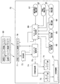
図1に本発明の一実施態様にかかるプリンタ2の機能ブロック図を示す。図1の機能ブロック図も図8と同様に主用部のみを示している。図1のプリンタ2の構成はプリンタ2からホスト装置90へのデータの送信を制御するための送信部10を設けた点が、図8のプリンタ70と異なる。図1においては、図8のプリンタ70と同一の部分には、プリンタ70と同一の番号を付してあり、詳細な説明は省略する。
【0032】
送信部10は、プリンタ2からホスト装置90へデータを送信する際に、1バイト単位でホスト装置90が受信可能状態であるかどうかを確認しながら送信する。ホスト装置90が送信途中でビジー状態になると、送信を一時停止して、ホスト装置90が受信可能な状態になったときに残りのデータを送信する。
【0033】
図2を用いて本発明にかかる送信部10の実施態様を説明する。図2は、送信部10の基本構成の一実施態様を示す機能ブロック図である。送信部10は送信制御部11、送信バッファ12及びポインタ13により構成される。ステータス監視部80から、制御信号が送信制御部11に送信され、同時にステータスデータが送信バッファ12に送られると、送信制御部11はホスト装置90がビジーかどうかを確認し、送信バッファ12に記憶されているステータスデータを送信する。
【0034】
本例の送信部10では、ASBステータス専用バッファ14、PIR専用バッファ15、マージ処理部16、XOFF送信処理部17及び信号線ステータス処理部18が設けられている。ASBステータス専用バッファ14には、送信バッファ78に何らかの送信データが格納されている場合に、ASBステータスが一時記憶される。ASBステータスとは、既に説明したとおり、自動ステータス報告機能(ASB)に基づくステータス情報であり、本例では4バイトから構成される。
【0035】
プロセスIDレスポンス(以下、PIRという。)専用バッファには、送信バッファ12に何らかの送信データが格納されている場合に、PIRデータが一時的に格納される。なお、PIRデータは、ホスト装置が制御コマンドや印刷データに任意に挿入してプリンタに送信したプロセスIDに応じて送信されるデータであり、当該制御コマンドや印刷データがプリンタによって処理されたことを示すものである。これにより、ホスト装置はプリンタ2の内部実行状態と同期を取りながらデータの送信を行うことができる。
【0036】
本例においては、XOFF信号、信号線ステータス等の特定の送信データは、他の送信データより高い優先順位で送信するように送信制御部11により制御される。XOFF送信処理部17は、プリンタ2からの受信禁止信号(XOFF)を最優先でホスト装置に送信する。信号線ステータス処理部18は、プリンタ2がオフライン状態になったとときにそのステータス情報をホスト装置90に伝えるもので、XOFFに次ぐ優先順位でホスト装置に送信される。XOFF信号及び信号線ステータスはいずれも送信バッファ12を経由することなく直接送信ドライバ78を経由してホスト装置90に送信される。
【0037】
マージ処理部16は、ASB専用バッファ14またはPIR専用バッファ15がバッファフルの場合に、後続する最新のステータス情報と、その変化履歴を記憶保持するために変化履歴情報を合成するものである。
【0038】
送信部10のステータス情報の受信について説明する。ステータス監視部80からステータス情報及び制御信号が送信されると、制御信号は送信制御部11に入力され、ステータスデータは送信バッファ12に一時記憶される。送信バッファ12の記憶容量は、自由に設定可能である。例えば、128バイトと設定することも可能である。
【0039】
ポインタ13は次に送信するデータの位置を示す読出ポインタ13aと、次に送信バッファ12に格納する位置を示す書込ポインタ13bとを有している。送信バッファ12にステータスデータを一時記憶させると、この書込ポインタ13bがインクリメントされる。なお、両ポインタとも送信バッファ12が設定されているRAM内の送信バッファに対応するアドレス範囲を移動するように、制御される。即ち、ポインタをインクリメントして当該アドレス範囲の最大値を超えた場合には、当該アドレス範囲の最小値に設定されるように制御する。このようなバッファ構造はリングバッファとして知られている。
【0040】
送信バッファがバッファフルである場合には、原則として、送信バッファ12の空きができたときに送信されるべき次のステータス情報が格納される。但し、ASBステータス情報、PIRデータはその性質上、データ発生の頻度が高い場合には格納すべきデータ量が膨大になることが考えられるため、専用バッファ14及び15をそれぞれ設け、これらに一時記憶された後に送信バッファ12に転送される。
【0041】
専用バッファ14又は15もバッファが満杯(バッファフル)となった場合等、所定の場合には、マージ処理部16により、ASB等のステータス情報の変化履歴を作成し、最新発生のステータス情報とともに専用バッファ14、15にこれらの変化履歴を一時記憶する等の、格納される情報の性質に応じたマージ処理が行われる。なお、マージ処理の詳細については後述する。
【0042】
(通常通信データの送信処理動作手順の説明)
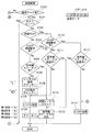
まず、図2及び図3を用いて、送信部10の送信処理動作の手順を説明する。図3は、送信部10の送信時の制御動作手順を説明するためのフローチャートである。
【0043】
図3の右上のテーブルL・ID・S1・S2・S3・S4は送信バッファ12に記憶されているデータを例示しており、S1・S2・S3・S4がホスト装置90に送信される。
【0044】
送信制御部11は、送信バッファ12にデータがあるかどうかを確認する。これは、上記の書込ポインタ13bと読出ポインタ13aとを比較し、値が同一で有れば送信バッファ12が空であると判断することができる。そして送信データがあると(S100;Yes)、ホスト装置90がビジーかどうかを確認する(S101)。ホスト装置90がビジーであると、送信処理をせずにホスト装置90が受信可能な状態になるのを待つ(S101;Yes)。ホスト装置90がビジーでなければ(S101;No)、現在、プリンタ2が一連の送信データを送信している途中か否かを確認する(S102)。今、データ送信を開始しようとしているところであり送信中では無いので(S102;No)、次の工程に進み、XOFF送信要求の有無を確認する(S103)。XOFF送信要求がなければ、信号線ステータスの有無を確認し(S104)、いずれも無ければ(S103及び104;No)、送信バッファ12から最初のデータ、すなわち、これから送信するステータス情報の長さ“L”を読み出し、ポインタ13をインクリメントする(S105)。なお、ここで取得したステータス情報の長さLはRAMに格納され、本送信ループのループカウンタの初期値として用いられる。次に送信バッファ12から“ID”を読み出し、送信データの種類(ステータスの種類等)を判別する(S106)。工程S108では送信バッファ12から次のデータ“S1”が読み出されて、ホスト装置90に送信される。その後ポインタ13がインクリメントされて、次の送信データ“S2”を指定した状態で、1バイトの送信が終了する(S109)。なお、この処理の中で上述のループカウンタがデクリメントされる。
【0045】
次の1バイトの送信も同様の処理、即ち本送信ループを繰り返す。先ず送信データがあるかどうかを確認する(S100)。今、送信データ(S2〜S4)が残っているので、次の工程(S101)に進み、ホストビジーかどうかが確認される(S101)。ビジーであれば、ホスト装置がレディーになるまで送信処理は一時停止され(S101;Yes)。ホストビジーでない場合には(S101;No)、現在送信中かどうかが確認される(S102)。データ送信中か否かは、上述のループカウンタの値が零か否かで判断することができる。零の場合は送信でないものとされる。今、データ送信中であるので(S102;Yes)、工程(S110、S111)に分岐し、XOFF信号及び信号線ステータスの有無が確認される。これらがない場合には(S110;No、S111;No)、ポインタ13で指定されているステータスS2が読み出され、ホスト装置90に送信される(S108)。1バイトの送信が終わると、次のステータスS3を送信するための準備としてポインタ13がインクリメントされる(S109)。同様の処理をループカウンタを用いて繰り返し行うことにより、ステータスデータ長Lで示された数のステータスデータを送信することができる。なお、上記のステータスデータの例では、ステータスS3及びS4を送信して、一連の送信データの送信処理を完了する。
【0046】
(XOFF信号、信号線ステータスの送信手順の説明)
次にステータスデータの送信中に、XOFF信号送信要求または信号線ステータスの送信要求が発生した場合について説明する。図2に示すように、XOFF信号及び信号線ステータスは送信バッファ12には記憶されることなく、XOFF信号処理部17及び信号線ステータス処理部18により直接送信ドライバ78を経由してホスト装置に送信される。この場合の送信処理は、送信バッファ12の送信データに優先して行われる。図3の送信制御フローを用いて説明する。
【0047】
今、第1番目のステータスデータ“S1”の送信準備中にXOFF送信要求があったとすると(S103;Yes)、Dに分岐し、XOFF信号(1バイト)を優先的に送信する。一連の送信データS2〜S4の送信途中にXOFF信号の送信要求があった場合(S110;Yes)にも、信号線ステータスの送信途中でない限り(S112;No)、XOFF信号を送信する。このように、XOFF信号は、信号線ステータスの送信途中の場合を除き、もっとも高い優先順位でホスト装置90に送信される。
【0048】
信号線ステータスが発生した場合には(S104;Yes)、信号線ステータスの長さ(複数バイトの設定が可能)及びそのIDがセットされて(S114)、信号線ステータスが1バイト送信される(S115)。信号線ステータスが数バイトある場合には、ホストビジーかどうかが確認され(S101)た後、信号線ステータス送信中であれば(S111;Yes又はS112;Yes)、残りの信号線ステータスが1バイトずつ順次送信される(S115)。これらの制御手順からわかるように、信号線ステータスはXOFF信号に次ぐ優先順位で送信される。
【0049】
次に、送信バッファ12に送信データがない場合について説明する。送信バッファ12にデータがない場合には、図3の工程S100からAに分岐する。図4に分岐Aの処理のフローチャートを示す。
【0050】
送信バッファ12に送信データが存在しない場合には、先ずASB専用バッファ14又はPIR専用バッファ15にASBステータスまたはPIRデータがあるかどうかが確認される(S120)。ASBステータスまたはPIRデータがあると、それらのデータが送信バッファ12に送信されて(S121)、図3のBに分岐する。図3では、すでに説明したとおり、ホスト装置90がビジーかどうかを確認した後(S101)、ステータスの送信が行われる。
【0051】
ASBステータス又はPIRデータが、専用バッファ14又は15に記憶されていない場合には(S120;No)、信号線ステータス又はXOFF信号送信要求の有無を確認して、送信要求がなければ(S122;No)送信要求を無しの設定を行い図3のCに分岐し送信処理を終了する。送信要求があればS122;Yes)、図3のBに分岐し、XOFF信号または信号線ステータスの送信処理を行う。
【0052】
(マージ処理の説明)
次にマージ処理について詳細に説明する。マージ処理は、図2の実施態様では送信バッファ12に送信データが有り、ASB専用バッファ14、PIR専用バッファ15に既にデータが格納されている状態で、さらにASBステータス、PIRデータがそれぞれ発生した場合に行われる。
【0053】
図5はマージ処理の手順を示すフローチャートである。先ずASBステータス又はPIRデータがステータス監視部80から出力されると、マージ処理部16(図2)は先ずマージ処理が必要か否かを判断する。例えば対応する専用バッファ14又は15に空きがない場合にはマージ処理が必要であると判断する(S130)。専用バッファに空きがあると(S130;No)、最新データを対応する専用バッファ14又は15に記憶する(S133)。但し、格納されるデータの性質上、複数発生するデータの変化経過が重要でない場合には、ホスト装置に送信するデータの量を減らすために、専用バッファに空きがあってもマージ処理が必要と判断されることもある。空きがない場合等、所定の場合には(S130;Yes)、専用バッファに記憶されている履歴データを更新し(S131)、その後に最新発生のASBステータス又はPIRデータを対応する専用バッファ14又は15に記憶する(S132)。
【0054】
図6を用いて、ASBステータスに関する履歴データの更新について説明する。なお、以下「最新発生データ」は「生成された最新のステータスデータ」を示し、「最新記憶データ」は「記憶された最新のステータスデータ」を示す。図6は、マージ処理部16とASB専用バッファ14の基本構成を説明するための機能ブロック図である。ASB専用バッファ14は、Newは4バイト(32ビット)からなるASBステータスデータ記憶部20と、Midは4バイト(32ビット)からなる変化履歴記憶部21とからそれぞれ構成されている。
【0055】
ASBステータス記憶部20には、最新発生のASBステータスが記憶される。変化履歴記憶部21には、後述するように、マージ処理部に対して順次送られた複数個のASBステータスデータに変化があったか否かの情報、即ち変化履歴データが格納される。
【0056】
送信バッファ12に空きができると、送信バッファに、変化履歴データと最新記憶データとの排他的論理和であるステータスの変化を定義する変更データが生成されて転送され、それに続いて最新記憶データが転送される。変化履歴データと最新記憶データとの排他的論理和により生成された前記変更データは、変化があったステータス(ビット)については最新記憶データ中の対応するビットと逆の状態を示し、変化がなかったステータス(ビット)については同じ状態を示している。これにより、ホスト装置に最後に送信されたステータスデータと最新記憶データとが同じであったとしても、それらの途中にステータスの変化が発生していれば、そのステータス変化をホスト装置に知らせることができる。
【0057】
ASBステータスデータは、その性質上、ステータスの変化の有無が重要であり、変化の順序等の過程を知る必要はない。また、最新の状態を早期にホスト装置に送信することが最も重要であるため、送信すべきASBステータスデータの量を極力減らすことが求められる。従って、最新の状態及び変化があったか否かの情報を各ステータス(ビット)について記憶することによって、必要最小限のデータを得ることができる。
【0058】
本例においては、以下の理由から、ASBステータスデータに変化があったか否かの情報を、変化履歴データと最新発生データとの排他的論理和により生成されたASBステータスの形になおしてからホスト装置に送信している。即ち、変化履歴データ自体はASBステータスではなく、そのままホスト装置に送信しても、ホスト装置では解釈できない。言い換えれば、ホスト装置では送信されたデータが「ASBステータスデータ」なのか「変化履歴データ」なのか識別することができないから、ホスト装置でASBステータスデータの変化履歴を復元することはできないからである。
【0059】
図中、Tranで示されているのは、ステータス監視部80から転送されてきた最新発生のASBステータスデータ22であり、4バイト(32ビット)で構成されている。なお、この実施態様では、ASBステータスは4バイトで構成されているものとして説明するが、ASBステータスのサイズ(レングス)は自由に設定可能である。
【0060】
図6は、マージ機能の一例を説明するための図であるため、タイミングその他の詳細な制御については省略してある。ステータス監視部80からステータスが転送されてきたときに、ASB専用バッファ14が空であれば、前述の通り、そのままASBステータスデータ記憶部20に記憶される。変化履歴記憶部21の初期値は零であり、その後は、送信バッファ12にそのデータを転送したときに零にクリアされる。
【0061】
マージ処理部16には、ASBステータスデータの各ビットに対応して変化検出部23−1〜23−32が設けられている。各マージ検出部23には排他的オアゲート24とオアゲート25が設けられており、記憶済みのデータビットNew1に対して新しいビットTran1に変化があれば“1”を出力するように構成されている。排他的オアゲート24の出力は、オアゲート25に入力され、そこで、変化履歴データの対応するビットMid1と論理和がとられる。
【0062】
従って、オアゲート25の出力は、送信バッファ12にASBステータスデータを転送した後に発生したASBステータスの各ビットに一度でも変化があると、“1”が出力されることになる。即ち変化があったという情報が変化履歴記憶部21に保持される。オアゲート25の出力は、変化履歴記憶部の対応するビットに入力されており、ENB2のタイミングで変化履歴記憶部21のデータが更新される。これにより、変化履歴記憶部21の出力ビットから、ASBステータスの変化を知ることが可能となる。
【0063】
ENB2による変化履歴記憶部21の更新が終了した後に、ENB1が活性状態となり、最新発生のステータスデータTran1〜32がASBステータスデータ記憶部20に記憶される。ASBステータスデータ記憶部20及び変化履歴記憶部21はASB専用バッファの一部に設けてもよい。この場合には、ASB専用バッファ14には、最新ASBステータスと、変化履歴が記憶されており、上述のように、送信バッファ12に空きができたときに、先ず最新ASBステータスデータと変化履歴データとの排他的論理和が、次に最新ASBステータスデータが順次転送される。
【0064】
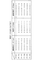
図7を用いて、これらのデータの変化をより具体的に説明する。図7は、最新発生データ(Tran)、変化履歴データ(Mid)及び最新記憶データ(New)の変化を示す図である。図7では、説明を簡単にするためにASBステータスデータの一部(1バイト(8ビット))について例示している。
【0065】
送信バッファ12に送信データがあるため、ASBを記憶できない状況下、ASBステータス(データ1)が転送されてきたとする。今、ASB専用バッファ14がマージ処理を必要とする状態ではないため、データ1がそのままASBステータスデータ記憶部20に記憶され、マージ処理は終了する(図5のS130、S133)。
【0066】
この状態で、次のASBステータスデータ(データ2)が転送されると、マージ処理が実質的に起動され(同S130)、まず変化履歴が作成される。最新記憶データNewのビット1であるNew1が“1”でありデータ2のビット1(Tran1)が“0”であるため、変化履歴データのビット1(Mid1)は“1”となり、また、“0”であったNew2が“1”(Tran2)に変化しているため、変化履歴データのMid2も“1”となる(同S131)。その後、最新記憶データNewにデータ2(Tran)の内容がそのまま記憶される(同S132)。
【0067】
その後、データ3がステータス監視部80から転送されると、同様にして、変化履歴データのビット3(Mid3)が“1”に変化するとともに、ビット1及び2(Mid1、Mid2)は“1”の状態に維持される。その後に、データ3がそのまま最新記憶データ(New)として記憶される。
【0068】
同様にしてデータ4、データ5が順次転送されると、変化履歴データのビット4、ビット5(Mid4、5)が順次“1”になり、最新記憶データNewとして最新発生のデータ5(Tran)が記憶される。
【0069】
データ6が転送された場合は、ビット1が“0”(New1)から“1”(Tran1)に、ビット5が“1”(New5)から“0”(Tran5)に、それぞれ変化しているが、これらに対応する変化履歴データの各ビット(Mid1、5)は既に“1”にセットされているので、変化履歴データは変化しない。
【0070】
この状態で、送信バッファ12への転送が可能になった場合は、上述のように、データ6の処理後の最新記憶データNew「00000001」と変化履歴データMid「00011111」との排他的論理和が演算され(「00011110」)、当該排他的論理和が先ず送信バッファ12へ転送される。そして次に、最新記憶データNewが送信バッファ12に転送される。
【0071】
上述の実施形態においては、ASBステータスデータの変化過程の情報が不要なものとしているが、例えば各ステータスの変化する順序等の変化過程情報を専用バッファ容量の許す限り保存したいという場合には、上記の実施形態に以下の構成を追加すればよい。即ち、専用バッファとしてFIFOバッファを用い、ステータス監視部80から転送されたASBステータスデータ(Tran)をこのFIFOバッファに入力する。一方、このFIFOバッファがあふれた場合には、その出力を図6に示すマージ回路に入力し、最新ASBステータスデータ(New)及び変化履歴データ(Mid)を生成し、RAM内の所定のアドレスに格納する。但し、この場合の最新ASBステータスデータは、真の最新データではないことに留意されたい。送信バッファ12にASBステータスデータを転送する場合には、上記の実施形態と同様に、変化履歴データと最新ASBステータスデータとの論理和、最新ASBステータスデータ、FIFOバッファの出力データの順に転送する。
【0072】
また、PIRデータは所定のプロセスの進捗状況をホスト装置が把握するためのデータであり、その性質上、中間履歴情報が必要でないため、未送信のPIRデータがPIR専用バッファに格納されている場合には、最新のPIRデータへの上書き処理を行う。
【0073】
尚、上述の実施態様においては、プリンタなどの端末装置からホスト装置へのデータの送信についてのみ説明したが、端末装置内に独立動作するインターフェース手段を設け、そのインターフェース手段とデータ通信する場合もホスト装置との通信の場合と同様である。すなわち、端末装置内のインターフェース手段に対して、1バイト単位で送信データを送信する送信制御は本発明の予定するところである。
【0074】
以上説明したように本発明によると、連続して発生するステータス情報については、専用バッファを設けるとともにステータスの変化履歴を記憶し、ホスト装置には最新のステータス情報とそれに至るステータスの変化を定義する変更データのみを送信するよう構成して、送信のためのバッファを少なくすることが可能になる他、通信負荷を大幅に減少させることも可能となる。
【図面の簡単な説明】
【図1】本発明の1実施態様にかかるプリンタ2の機能ブロック図を示す。
【図2】第2の実施態様にかかる送信部10−2の基本構成を示す機能ブロック図である。
【図3】第2の実施態様にかかる送信部10-2の送信時の制御動作を説明するためのフローチャートである。
【図4】図3の工程S100からの分岐Aのフローチャートである。
【図5】マージ処理の手順を示すフローチャートである。
【図6】マージ処理部16とASB専用バッファ14の基本構成を説明するための機能ブロック図である。
【図7】最新発生データ(Tran)、変化履歴データ(Mid)及び最新記憶データ(New)の変化を示す図である。
【図8】図8は従来技術に係るプリンタ70の主要部のみを示す機能ブロック図。
【符号の説明】
2 本発明に係るプリンタ
10 送信部
11 送信制御部
12 送信バッファ
14 ASB専用バッファ
16 マージ処理部
20 ASBステータスデータ記憶部
21 変化履歴記憶部
22 最新発生のASBステータスデータ
23 変化検出部
24 排他的オアゲート
25 オアゲート[0001]
BACKGROUND OF THE INVENTION
The present invention relates to a printing device, a display device, and a cash acceptance used inside a device such as a KIOSK terminal device installed in an automatic cash savings machine (ATM), an automatic cash withdrawal machine (CD), a POS system, a convenience store, etc. More particularly, the present invention relates to a transmission control device and a transmission control method for transmitting data from these terminal devices to a host device.
[0002]
[Prior art]
Conventionally, an ATM, a CD, a POS terminal device, a KIOSK terminal device, and the like have a main control device such as a personal computer (hereinafter referred to as a PC or a host device), and are further controlled by this host device. A plurality of terminal devices having various functions such as a printing device, various display devices, a cash storage device, and a barcode reader are provided. The host device is a unified operation of each of the above-mentioned various terminal devices so that a device such as an ATM or POS terminal (hereinafter referred to as a main device) can perform its original function. Is controlling. Specifically, the host device and the terminal device are connected by a communication line, and the operation of the terminal device is controlled by transmitting a control command and other data to the terminal device. The terminal device transmits various data to the host device according to the function, and also transmits status information such as the operation status of the terminal device to the host device in response to a request from the host device. Many of the various terminal devices provided inside the main unit are connected to the host device via a serial port (RS-232C, etc.), and commands, processing data, etc. are transmitted between the host device and the various terminal devices. Transferred to each other.
[0003]
An interface device is provided between these devices, and a control line for controlling communication is prepared. For example, a data terminal ready (DTR) signal allows the terminal device side to indicate to the host device whether or not data can be received. When the DTR signal becomes active (active state), the host device side activates the data set ready (DSR) signal, and transmits data after confirming that both are operable. This prevents data loss in data communication.
[0004]
The present invention can be applied to any terminal, but in the following, for the sake of brevity, the description will be made using a terminal printer (hereinafter simply referred to as a printer) frequently used in ATMs, POS systems, and the like. To do.
[0005]
In a printer, a printing operation cannot be performed unless various supplies such as printing paper and ink are satisfied. Therefore, the remaining amount of printing paper and ink can be confirmed from the host device. Specifically, when the remaining amount of printing paper or ink is low, the ink near end or paper near end status can be sent as transmission data to the host device when the ink near end or paper near end status is completely lost. ing. The status information is not limited to this, and a lot of information such as printer cover open, ink tank removal, printing paper jam, power supply abnormality and the like is transmitted to the host device.
[0006]
For example, the printer cannot operate as a terminal due to various reasons such as the reception buffer is full (reception buffer is full), an error condition such as a jam of printing paper occurs, or the cover is open ( Hereinafter, such a state may be referred to as offline). In the offline state, it is necessary to notify the host device of this state from the printer that is the terminal device, and to stop transmission of data from the host device.
[0007]
In addition, transmission of data to the host device is also performed by a status request command from the host device. There are various status request commands. For example, a host device that sends status information by sending commands individually as necessary for status confirmation, or a terminal device that automatically sends status information whenever there is a change in status Use the function (hereinafter referred to as auto status back: ASB)Etc.There is.
[0008]
The status information is composed of 1 to several bytes according to the type, and each bit of each status information indicates various statuses.
[0009]
Hereinafter, a data transmission control apparatus according to the prior art will be described in more detail with reference to FIG. FIG. 8 is a functional block diagram showing only the main part of the
[0010]
Control of the
[0011]
For example, the
[0012]
The
[0013]
The
[0014]
Status information such as print status and reception buffer full is also transmitted to the
When a status request command is transmitted from the
The status of the
[0015]
The status information may be one byte or several bytes. If it is 1 byte, 8 bits, that is, 8 types of status information can be transmitted, and if the number of bytes increases, the status information increases accordingly. Now, it is assumed that the ASB status information is composed of 4 bytes, and a case where this information is transmitted to the
[0016]
If the ASB function is set and there is a change in the designated status, the
[0017]
[Problems to be solved by the present invention]
The status information as described above is sequentially transmitted to the host device as transmission data. Since the status information such as ASB automatically transmits the status information to the host device whenever the status is changed, status information to be transmitted one after another may occur. As a result, when the transmission buffer on the terminal side is full (buffer full) and cannot be stored, status data generated after the buffer full is lost.
[0018]
Accordingly, an object of the present invention is to provide a transmission control device and a transmission control method that can be transmitted to a host device without losing status information continuously generated in a terminal device. Another object of the present invention is to provide a status information transmission control method capable of reducing the transmission buffer and greatly reducing the communication load.
[0019]
[Means for Solving the Problems]
Therefore, the present invention provides a status that occurs continuously.dataAbout at least the latest status with a dedicated bufferdataAnd its status change history are stored, and the latest status is stored in the host device.dataAnd the status change history leading to itChange data, which is information indicating the status data, is immediately before the latest status data in the same data format as the status data.By sendingThe host device can reliably know that the status has changed, andIt is possible to reduce the buffer for transmission, and the communication load can be greatly reduced.Terminal apparatus having automatic status return means and itsA control method can be provided. As a result, the status change history can be reliably stored and transmitted with a small amount of data.
[0020]
The embodiments of the present invention are outlined below.
[0021]
A terminal device according to the present invention is configured to connect to a host, and in a terminal device having automatic status return means for automatically generating status data in response to a status change and transmitting the status data to the host ,
Change data that defines a change in status that occurred during the period from when the status data was sent to the host last time to when the latest status data is generated is referred to as the latest status data.Indicates whether status data has changed during the periodMeans for generating by exclusive OR of change history data;
Before sending the latest status data to the host, the change dataIn the same data format as status dataMeans for transmitting to the host;
It is provided with.
The change history data is stored in a dedicated buffer that temporarily stores at least the latest status data and the change history data of the status, and the status data immediately before the latest status data is stored; the latest status data; , And the output of the logical sum of the change history data immediately before the update stored separately in the dedicated buffer.
Further, the terminal device according to the present invention obtains the latest status data.SaidStore in dedicated bufferOnly processOrOr claim 2The data processing described inAfter performing the process of storing the latest status data in the dedicated buffer.Means is provided for determining whether to perform the determination based on the availability of the dedicated buffer.
Also, the terminal device control method of the present invention is configured to connect to a host, and automatically generates status data in response to a status change, and transmits the status data to the host. In the control method of the terminal device having
Change data that defines a change in status that occurred during the period from when the status data was sent to the host last time to when the latest status data is generated is referred to as the latest status data.Indicates whether status data has changed during the periodGenerating by exclusive OR of change history data;
Before sending the latest status data to the host, the change dataIn the same data format as status dataTransmitting to the host;
It is provided with.
[0022]
According to this aspect, even if the transmission buffer becomes buffer full, the status change can be stored with a small amount of data, and the transmission load can be reduced. Status information continuously generated in the terminal device can be transmitted to the host device without being lost. As a result, it is possible to reduce the buffer for transmission, and it is possible to provide a status information transmission control method capable of significantly reducing the communication load. In addition, the status change history can be reliably stored and transmitted with a small amount of data. Furthermore, the status change information can be reliably transmitted to the host device without loss.
[0023]
In the transmission control device according to the second aspect of the present invention, the status information that is stored in the dedicated buffer and for which the change history data is generated by the change history generating means is composed of a predetermined type of status information. Features. As a result, it is possible to selectively create and transmit change history data according to importance or the like.
[0024]
In the transmission control device according to the third aspect of the present invention, the status information indicates one status with or without one bit.The
The transmission control apparatus according to the fourth aspect of the present invention further includes change history data storage means for storing change history data, and the control means replaces the change history data with the dedicated buffer in the change history data storage means. It is characterized by controlling to memorize. It is also possible to provide storage means other than the dedicated buffer for storage.
[0025]
The transmission control apparatus according to the fifth aspect of the present invention further includes a first dedicated buffer of a first-in first-out (FIFO) storage method for storing status information, and status information output from the last stage of the first dedicated buffer. And a second dedicated buffer for storing the latest status information output from the last stage of the first dedicated buffer, and the change history generating means is provided with the first dedicated buffer. The change history data is generated based on the output status information, and the control means stores status information and change history data from the second dedicated buffer to the transmission buffer when the status information and change history data are stored in the second dedicated buffer. When the change history data is transferred and the status information is not stored in the second dedicated buffer, the status information is stored. And controlling to transfer to the transmission buffer from the first dedicated buffer were sequentially.
[0026]
As a result, a certain amount of status information is stored in the first dedicated buffer. When the change history data is stored when the first dedicated buffer becomes full, the first dedicated buffer is stored. All the contents of the status information can be stored up to the storage capacity.
[0027]
The transmission control method according to another aspect of the present invention includes: (a) checking whether the transmission buffer is buffer full, and storing the status information generated continuously in the transmission buffer when the buffer is not full; and (b) ) When the transmission buffer is buffer full, a step of generating change history data indicating the presence or absence of continuous change of the status information that cannot be stored in the transmission buffer; and (c) at least the latest status information and the change history data; And (d) transferring the latest status information and change history data stored therein to the transmission buffer when the buffer full of the transmission buffer is released.
In the transmission control method according to another aspect of the present invention, the status information to be processed in the step (b), the step (c) and the step (d) includes a predetermined type of status information. It is characterized by that.
[0028]
In the transmission control method according to another aspect of the present invention, the status information to be processed in step (b), step (c), and step (d) has one status depending on the presence or absence of one bit. The step (c) of generating change history data includes a step of creating a change history by sequentially calculating a logical OR in units of bits for continuously received status information.
[0029]
The transmission control method according to another aspect of the present invention includes (a) checking whether or not the transmission buffer is buffer full, and storing the status information generated continuously in the transmission buffer when the buffer is not full, and (b) ) When the transmission buffer is full, a step of storing status information that cannot be stored in the buffer in the first dedicated buffer of the first-in first-out (FIFO) storage method; and (c) continuous from the last stage of the first dedicated buffer. And (d) status information output from the last stage of the first dedicated buffer, wherein at least the latest status information and changes are generated. Storing the history data in the second dedicated buffer; and (e) when the buffer full of the transmission buffer is released, Status information and change history data are transferred from the second dedicated buffer to the transmission buffer when status information and change history data are stored in the file, and status information is transferred when no status information is stored in the second dedicated buffer. Transferring the data from the first dedicated buffer to the transmission buffer in the order in which they are stored.
[0030]
DETAILED DESCRIPTION OF THE INVENTION
Hereinafter, embodiments of the present invention will be described in detail with reference to the drawings. As described above, the present invention can be applied to various terminal devices. However, in the following embodiments, the present invention is frequently used for ATM, POS, KIOSK terminals, and the like, and the amount of data transmission / reception with the host device is small. A printer having many types and status types will be described. In particular, the following description will be made using a printer used in the POS system.
[0031]
FIG. 1 is a functional block diagram of a
[0032]
When transmitting data from the
[0033]
An embodiment of the
[0034]
In the
[0035]
In a process ID response (hereinafter referred to as PIR) dedicated buffer, PIR data is temporarily stored when any transmission data is stored in the
[0036]
In this example, specific transmission data such as an XOFF signal and a signal line status is controlled by the
[0037]
When the ASB
[0038]
The reception of status information by the
[0039]
The
[0040]
When the transmission buffer is buffer full, in principle, the next status information to be transmitted when the
[0041]
In a predetermined case, such as when the
[0042]
(Explanation of normal communication data transmission processing procedure)
First, the procedure of the transmission processing operation of the
[0043]
The tables L, ID, S1, S2, S3, and S4 in the upper right of FIG. 3 exemplify data stored in the
[0044]
The
[0045]
The same processing, that is, this transmission loop is repeated for the next 1-byte transmission. First, it is confirmed whether there is transmission data (S100). Since transmission data (S2 to S4) remains, the process proceeds to the next step (S101) to check whether the host is busy (S101). If it is busy, the transmission process is suspended until the host device becomes ready (S101; Yes). If the host is not busy (S101; No), it is confirmed whether transmission is currently being performed (S102). Whether or not data transmission is in progress can be determined by whether or not the value of the loop counter is zero. If it is zero, it is not transmitted. Since data is currently being transmitted (S102; Yes), the process branches to steps (S110, S111), and the presence or absence of the XOFF signal and signal line status is confirmed. If there is no such information (S110; No, S111; No), the status S2 designated by the
[0046]
(Explanation of XOFF signal and signal line status transmission procedure)
Next, a case where an XOFF signal transmission request or a signal line status transmission request occurs during transmission of status data will be described. As shown in FIG. 2, the XOFF signal and the signal line status are not stored in the
[0047]
If there is an XOFF transmission request during preparation for transmission of the first status data “S1” (S103; Yes), branch to D and preferentially transmit an XOFF signal (1 byte). Even when there is an XOFF signal transmission request during the transmission of a series of transmission data S2 to S4 (S110; Yes), the XOFF signal is transmitted unless the signal line status is being transmitted (S112; No). As described above, the XOFF signal is transmitted to the
[0048]
When the signal line status is generated (S104; Yes), the length of the signal line status (a plurality of bytes can be set) and its ID are set (S114), and 1 byte of the signal line status is transmitted (S114). S115). If the signal line status is several bytes, it is confirmed whether or not the host is busy (S101), and if the signal line status is being transmitted (S111; Yes or S112; Yes), the remaining signal line status is 1 byte. The data are sequentially transmitted (S115). As can be seen from these control procedures, the signal line status is transmitted in the priority order next to the XOFF signal.
[0049]
Next, a case where there is no transmission data in the
[0050]
If there is no transmission data in the
[0051]
If the ASB status or PIR data is not stored in the
[0052]
(Description of merge processing)
Next, the merge process will be described in detail. In the embodiment shown in FIG. 2, the merge processing is performed when there is transmission data in the
[0053]
FIG. 5 is a flowchart showing the procedure of the merge process. First, when the ASB status or PIR data is output from the
[0054]
The update of the history data regarding the ASB status will be described with reference to FIG.Hereinafter, “latest generated data” indicates “generated latest status data”, and “latest stored data” indicates “stored latest status data”.FIG. 6 is a functional block diagram for explaining the basic configuration of the
[0055]
The ASB
[0056]
When the
[0057]
Because of the nature of ASB status data, the presence or absence of a status change is important, and it is not necessary to know the process such as the order of change. In addition, since it is most important to transmit the latest state to the host device at an early stage, it is required to reduce the amount of ASB status data to be transmitted as much as possible. Therefore, the minimum necessary data can be obtained by storing, for each status (bit), information indicating whether or not there is a latest state and a change.
[0058]
In this example, for the following reason, the information indicating whether or not the ASB status data has changed is changed to the ASB status generated by exclusive OR of the change history data and the latest occurrence data, and then the host device. Is sending to. That is, the change history data itself is not an ASB status, and even if it is transmitted to the host device as it is, it cannot be interpreted by the host device. In other words, since the host device cannot identify whether the transmitted data is “ASB status data” or “change history data”, the host device cannot restore the change history of the ASB status data. .
[0059]
In the figure, what is indicated by Tran is the most recently generated
[0060]
FIG. 6 is a diagram for explaining an example of the merge function, and therefore detailed control of timing and the like is omitted. If the ASB
[0061]
The
[0062]
Accordingly, the output of the
[0063]
After the update of the change
[0064]
These data changes will be described more specifically with reference to FIG. FIG. 7 is a diagram illustrating changes in the latest occurrence data (Tran), change history data (Mid), and latest storage data (New). FIG. 7 illustrates a part of ASB status data (1 byte (8 bits)) for ease of explanation.
[0065]
Assume that the ASB status (data 1) has been transferred in a situation where the ASB cannot be stored because there is transmission data in the
[0066]
In this state, when the next ASB status data (data 2) is transferred, the merge process is substantially activated (S130), and a change history is first created. Since New1 which is
[0067]
Thereafter, when the data 3 is transferred from the
[0068]
Similarly, when data 4 and data 5 are sequentially transferred, bit 4 and bit 5 (Mid 4 and 5) of the change history data are sequentially set to “1”, and the latest generated data 5 (Tran) as the latest stored data New. Is memorized.
[0069]
When data 6 is transferred,
[0070]
When transfer to the
[0071]
In the above-described embodiment, it is assumed that the information on the change process of the ASB status data is unnecessary. For example, when it is desired to save the change process information such as the change order of each status as long as the dedicated buffer capacity permits, The following configuration may be added to the embodiment. That is, a FIFO buffer is used as a dedicated buffer, and ASB status data (Tran) transferred from the
[0072]
Further, PIR data is data for the host device to grasp the progress status of a predetermined process, and because of its nature, intermediate history information is not required, and thus untransmitted PIR data is stored in a PIR dedicated buffer. In this case, the latest PIR data is overwritten.
[0073]
In the above embodiment, only the transmission of data from a terminal device such as a printer to a host device has been described. However, an interface unit that operates independently is provided in the terminal device, and the host device also performs data communication with the interface unit. This is similar to the case of communication with the device. That is, the transmission control for transmitting transmission data in units of 1 byte to the interface means in the terminal device is a place planned by the present invention.
[0074]
As described above, according to the present invention, for status information that occurs continuously, a dedicated buffer is provided and a status change history is stored, and the latest status information and the status change leading to it are stored in the host device.Change data that definesIn addition to reducing the number of buffers for transmission, the communication load can be greatly reduced.
[Brief description of the drawings]
FIG. 1 is a functional block diagram of a
FIG. 2 is a functional block diagram showing a basic configuration of a transmission unit 10-2 according to a second embodiment.
FIG. 3 is a flowchart for explaining a control operation at the time of transmission of a transmission unit 10-2 according to the second embodiment;
FIG. 4 is a flowchart of a branch A from step S100 in FIG.
FIG. 5 is a flowchart showing a procedure of merge processing.
6 is a functional block diagram for explaining basic configurations of a
FIG. 7 is a diagram showing changes in latest occurrence data (Tran), change history data (Mid), and latest storage data (New).
FIG. 8 is a functional block diagram showing only the main part of a
[Explanation of symbols]
2 Printer according to the present invention
10 Transmitter
11 Transmission control unit
12 Transmission buffer
14 ASB dedicated buffer
16 Merge processing part
20 ASB status data storage
21 Change history storage
22 Latest ASB status data
23 Change detector
24 Exclusive OR Gate
25 or gate
Claims (6)
前回ホストにステータスデータを送信した時点から、最新のステータスデータを生成する現時点までの期間に発生したステータスの変化を定義する変更データを、前記最新のステータスデータと前記期間中にステータスデータに変化があったか否かを示す変化履歴データの排他的論理和によって生成する手段と、
前記最新のステータスデータを前記ホストに送信する前に、前記変更データをステータスデータと同じデータ形式で前記ホストに送信する手段と、
を備えたことを特徴とする端末装置。In a terminal device configured to connect to a host, having automatic status return means for automatically generating status data in response to a status change and transmitting the status data to the host,
Change data that defines the status change that occurred during the period from the last time status data was sent to the host to the time when the latest status data is generated is changed to the latest status data and status data during the period. Means for generating by exclusive OR of change history data indicating whether or not there was ,
Means for sending the changed data to the host in the same data format as the status data before sending the latest status data to the host;
A terminal device comprising:
前回ホストにステータスデータを送信した時点から、最新のステータスデータを生成する現時点までの期間に発生したステータスの変化を定義する変更データを、前記最新のステータスデータと前記期間中にステータスデータに変化があったか否かを示す変化履歴データの排他的論理和によって生成する工程と、
前記最新のステータスデータを前記ホストに送信する前に、前記変更データをステータスデータと同じデータ形式で前記ホストに送信する工程と、
を備えたことを特徴とする端末装置の制御方法。In a control method of a terminal device configured to connect to a host, automatically generating status data in response to a status change, and having automatic status return means for transmitting the status data to the host,
Change data that defines the status change that occurred during the period from the last time status data was sent to the host to the time when the latest status data is generated is changed to the latest status data and status data during the period. Generating by exclusive OR of change history data indicating whether or not there was ,
Sending the changed data to the host in the same data format as the status data before sending the latest status data to the host;
A control method for a terminal device, comprising:
Priority Applications (11)
| Application Number | Priority Date | Filing Date | Title |
|---|---|---|---|
| JP2000387319A JP4524912B2 (en) | 2000-12-20 | 2000-12-20 | Terminal apparatus and control method thereof |
| CNB011437278A CN1207665C (en) | 2000-12-20 | 2001-12-19 | Terminal equipment sending control device and method |
| CNA2005100677395A CN1690994A (en) | 2000-12-20 | 2001-12-19 | Transmission control device and transmission control method for a terminal apparatus |
| SG200107838-5A SG131736A1 (en) | 2000-12-20 | 2001-12-19 | Terminal device and method of controlling transmission in the terminal device |
| KR1020010081053A KR100575916B1 (en) | 2000-12-20 | 2001-12-19 | Transmission control apparatus of terminal apparatus and transmission control method for the same |
| ES01130281T ES2258505T3 (en) | 2000-12-20 | 2001-12-20 | TERMINAL DEVICE AND METHOD TO CONTROL A TRANSMISSION IN THE TERMINAL DEVICE. |
| DE60119268T DE60119268T2 (en) | 2000-12-20 | 2001-12-20 | Terminal device and method for data transfer control in the terminal device |
| AT01130281T ATE325386T1 (en) | 2000-12-20 | 2001-12-20 | TERMINAL DEVICE AND METHOD FOR DATA TRANSMISSION CONTROL IN THE TERMINAL DEVICE |
| EP01130281A EP1217527B1 (en) | 2000-12-20 | 2001-12-20 | Terminal device and method of controlling transmission in the terminal device |
| US10/026,339 US6811334B2 (en) | 2000-12-20 | 2001-12-20 | Transmission control device and transmission control method for a terminal apparatus |
| US10/889,375 US7011461B2 (en) | 2000-12-20 | 2004-07-12 | Transmission control device and transmission control method for a terminal apparatus |
Applications Claiming Priority (1)
| Application Number | Priority Date | Filing Date | Title |
|---|---|---|---|
| JP2000387319A JP4524912B2 (en) | 2000-12-20 | 2000-12-20 | Terminal apparatus and control method thereof |
Publications (3)
| Publication Number | Publication Date |
|---|---|
| JP2002189640A JP2002189640A (en) | 2002-07-05 |
| JP2002189640A5 JP2002189640A5 (en) | 2007-10-18 |
| JP4524912B2 true JP4524912B2 (en) | 2010-08-18 |
Family
ID=18854279
Family Applications (1)
| Application Number | Title | Priority Date | Filing Date |
|---|---|---|---|
| JP2000387319A Expired - Fee Related JP4524912B2 (en) | 2000-12-20 | 2000-12-20 | Terminal apparatus and control method thereof |
Country Status (9)
| Country | Link |
|---|---|
| US (2) | US6811334B2 (en) |
| EP (1) | EP1217527B1 (en) |
| JP (1) | JP4524912B2 (en) |
| KR (1) | KR100575916B1 (en) |
| CN (2) | CN1690994A (en) |
| AT (1) | ATE325386T1 (en) |
| DE (1) | DE60119268T2 (en) |
| ES (1) | ES2258505T3 (en) |
| SG (1) | SG131736A1 (en) |
Families Citing this family (56)
| Publication number | Priority date | Publication date | Assignee | Title |
|---|---|---|---|---|
| JP4524912B2 (en) * | 2000-12-20 | 2010-08-18 | セイコーエプソン株式会社 | Terminal apparatus and control method thereof |
| JP3787535B2 (en) * | 2002-06-18 | 2006-06-21 | キヤノン株式会社 | Image processing apparatus and control method thereof |
| DE10232631A1 (en) * | 2002-07-18 | 2004-02-05 | OCé PRINTING SYSTEMS GMBH | Method and device for error handling in a printer or copier |
| JP2005007762A (en) * | 2003-06-19 | 2005-01-13 | Seiko Epson Corp | Printer, printing system, program and method for controlling terminal unit |
| US7513416B1 (en) * | 2004-07-29 | 2009-04-07 | Diebold Self-Service Systems | Cash dispensing automated banking machine deposit printing system and method |
| EP1630662B1 (en) | 2004-08-27 | 2013-01-02 | Seiko Epson Corporation | Printer and printer control method |
| JP2006062266A (en) | 2004-08-27 | 2006-03-09 | Seiko Epson Corp | Printer and control method for printer |
| US8006293B2 (en) | 2004-10-08 | 2011-08-23 | Sharp Laboratories Of America, Inc. | Methods and systems for imaging device credential acceptance |
| US7970813B2 (en) | 2004-10-08 | 2011-06-28 | Sharp Laboratories Of America, Inc. | Methods and systems for imaging device event notification administration and subscription |
| US8015234B2 (en) | 2004-10-08 | 2011-09-06 | Sharp Laboratories Of America, Inc. | Methods and systems for administering imaging device notification access control |
| US8115944B2 (en) | 2004-10-08 | 2012-02-14 | Sharp Laboratories Of America, Inc. | Methods and systems for local configuration-based imaging device accounting |
| US8051140B2 (en) | 2004-10-08 | 2011-11-01 | Sharp Laboratories Of America, Inc. | Methods and systems for imaging device control |
| US8384925B2 (en) | 2004-10-08 | 2013-02-26 | Sharp Laboratories Of America, Inc. | Methods and systems for imaging device accounting data management |
| US8060930B2 (en) | 2004-10-08 | 2011-11-15 | Sharp Laboratories Of America, Inc. | Methods and systems for imaging device credential receipt and authentication |
| US8006292B2 (en) | 2004-10-08 | 2011-08-23 | Sharp Laboratories Of America, Inc. | Methods and systems for imaging device credential submission and consolidation |
| US8060921B2 (en) | 2004-10-08 | 2011-11-15 | Sharp Laboratories Of America, Inc. | Methods and systems for imaging device credential authentication and communication |
| US8018610B2 (en) | 2004-10-08 | 2011-09-13 | Sharp Laboratories Of America, Inc. | Methods and systems for imaging device remote application interaction |
| US8001586B2 (en) | 2004-10-08 | 2011-08-16 | Sharp Laboratories Of America, Inc. | Methods and systems for imaging device credential management and authentication |
| US7934217B2 (en) | 2004-10-08 | 2011-04-26 | Sharp Laboratories Of America, Inc. | Methods and systems for providing remote file structure access to an imaging device |
| US8065384B2 (en) * | 2004-10-08 | 2011-11-22 | Sharp Laboratories Of America, Inc. | Methods and systems for imaging device event notification subscription |
| US8125666B2 (en) * | 2004-10-08 | 2012-02-28 | Sharp Laboratories Of America, Inc. | Methods and systems for imaging device document management |
| US7920101B2 (en) * | 2004-10-08 | 2011-04-05 | Sharp Laboratories Of America, Inc. | Methods and systems for imaging device display standardization |
| US8006176B2 (en) * | 2004-10-08 | 2011-08-23 | Sharp Laboratories Of America, Inc. | Methods and systems for imaging-device-based form field management |
| US8213034B2 (en) | 2004-10-08 | 2012-07-03 | Sharp Laboratories Of America, Inc. | Methods and systems for providing remote file structure access on an imaging device |
| US8171404B2 (en) | 2004-10-08 | 2012-05-01 | Sharp Laboratories Of America, Inc. | Methods and systems for disassembly and reassembly of examination documents |
| US7978618B2 (en) | 2004-10-08 | 2011-07-12 | Sharp Laboratories Of America, Inc. | Methods and systems for user interface customization |
| US8156424B2 (en) | 2004-10-08 | 2012-04-10 | Sharp Laboratories Of America, Inc. | Methods and systems for imaging device dynamic document creation and organization |
| US8051125B2 (en) | 2004-10-08 | 2011-11-01 | Sharp Laboratories Of America, Inc. | Methods and systems for obtaining imaging device event notification subscription |
| US8032608B2 (en) | 2004-10-08 | 2011-10-04 | Sharp Laboratories Of America, Inc. | Methods and systems for imaging device notification access control |
| US8001183B2 (en) | 2004-10-08 | 2011-08-16 | Sharp Laboratories Of America, Inc. | Methods and systems for imaging device related event notification |
| US8115947B2 (en) | 2004-10-08 | 2012-02-14 | Sharp Laboratories Of America, Inc. | Methods and systems for providing remote, descriptor-related data to an imaging device |
| US8049677B2 (en) | 2004-10-08 | 2011-11-01 | Sharp Laboratories Of America, Inc. | Methods and systems for imaging device display element localization |
| US7969596B2 (en) | 2004-10-08 | 2011-06-28 | Sharp Laboratories Of America, Inc. | Methods and systems for imaging device document translation |
| US8024792B2 (en) | 2004-10-08 | 2011-09-20 | Sharp Laboratories Of America, Inc. | Methods and systems for imaging device credential submission |
| US8115945B2 (en) | 2004-10-08 | 2012-02-14 | Sharp Laboratories Of America, Inc. | Methods and systems for imaging device job configuration management |
| US8115946B2 (en) | 2004-10-08 | 2012-02-14 | Sharp Laboratories Of America, Inc. | Methods and sytems for imaging device job definition |
| US8120797B2 (en) | 2004-10-08 | 2012-02-21 | Sharp Laboratories Of America, Inc. | Methods and systems for transmitting content to an imaging device |
| US8120793B2 (en) * | 2004-10-08 | 2012-02-21 | Sharp Laboratories Of America, Inc. | Methods and systems for displaying content on an imaging device |
| US8120798B2 (en) | 2004-10-08 | 2012-02-21 | Sharp Laboratories Of America, Inc. | Methods and systems for providing access to remote, descriptor-related data at an imaging device |
| US8032579B2 (en) | 2004-10-08 | 2011-10-04 | Sharp Laboratories Of America, Inc. | Methods and systems for obtaining imaging device notification access control |
| US8237946B2 (en) | 2004-10-08 | 2012-08-07 | Sharp Laboratories Of America, Inc. | Methods and systems for imaging device accounting server redundancy |
| US8120799B2 (en) | 2004-10-08 | 2012-02-21 | Sharp Laboratories Of America, Inc. | Methods and systems for accessing remote, descriptor-related data at an imaging device |
| US8023130B2 (en) | 2004-10-08 | 2011-09-20 | Sharp Laboratories Of America, Inc. | Methods and systems for imaging device accounting data maintenance |
| US8035831B2 (en) | 2004-10-08 | 2011-10-11 | Sharp Laboratories Of America, Inc. | Methods and systems for imaging device remote form management |
| US8001587B2 (en) | 2004-10-08 | 2011-08-16 | Sharp Laboratories Of America, Inc. | Methods and systems for imaging device credential management |
| US7426510B1 (en) * | 2004-12-13 | 2008-09-16 | Ntt Docomo, Inc. | Binary data categorization engine and database |
| US8428484B2 (en) | 2005-03-04 | 2013-04-23 | Sharp Laboratories Of America, Inc. | Methods and systems for peripheral accounting |
| US20070023447A1 (en) * | 2005-07-26 | 2007-02-01 | Jeong Min Yoon | Discharger for tablets |
| JP2007042098A (en) * | 2005-07-29 | 2007-02-15 | Sharp Corp | Content display method, content transmission method, image processing device, and remote computation device |
| JP2007074320A (en) * | 2005-09-07 | 2007-03-22 | Matsushita Electric Ind Co Ltd | Network equipment apparatus |
| US7693984B2 (en) * | 2005-12-29 | 2010-04-06 | Panasonic Electric Works Co., Ltd. | Systems and methods for providing current status data to a requesting device |
| US8345272B2 (en) | 2006-09-28 | 2013-01-01 | Sharp Laboratories Of America, Inc. | Methods and systems for third-party control of remote imaging jobs |
| US8156295B2 (en) * | 2009-04-03 | 2012-04-10 | National Instruments Corporation | Four-slot asynchronous communication mechanism with decreased latency |
| JP5746501B2 (en) * | 2010-12-20 | 2015-07-08 | キヤノン株式会社 | Printing apparatus and processing method thereof |
| US10686881B2 (en) * | 2013-08-29 | 2020-06-16 | Seiko Epson Corporation | Transmission system, transmission device, and data transmission method |
| WO2019064812A1 (en) * | 2017-09-26 | 2019-04-04 | 日本電産株式会社 | Information transmission device and program |
Citations (1)
| Publication number | Priority date | Publication date | Assignee | Title |
|---|---|---|---|---|
| JPS61125258A (en) * | 1984-11-20 | 1986-06-12 | Fujitsu Ltd | Status transition announcement system |
Family Cites Families (27)
| Publication number | Priority date | Publication date | Assignee | Title |
|---|---|---|---|---|
| JPS59229658A (en) * | 1983-06-10 | 1984-12-24 | Nec Corp | Information processor |
| JPH0646830B2 (en) * | 1987-08-21 | 1994-06-15 | 富士通株式会社 | State change processing method |
| EP0331720B1 (en) * | 1987-09-21 | 1993-10-27 | Unisys Corporation | Peripheral controller |
| JPH05191454A (en) * | 1992-01-16 | 1993-07-30 | Nec Corp | Data transfer system |
| JPH06202715A (en) * | 1992-12-28 | 1994-07-22 | Fuji Facom Corp | State change detecting and recording circuit |
| JP3483044B2 (en) * | 1993-11-16 | 2004-01-06 | セイコーエプソン株式会社 | Printing apparatus, printing system, and status change detection method |
| US6021431A (en) * | 1994-03-29 | 2000-02-01 | The United States Of America As Represented By The Secretary Of The Navy | Method of retrieving and storing computer peripheral data |
| JP2846238B2 (en) * | 1994-04-28 | 1999-01-13 | 三菱電機株式会社 | System control management method by error trace |
| JP3127716B2 (en) * | 1994-06-02 | 2001-01-29 | セイコーエプソン株式会社 | Printer |
| US5802546A (en) * | 1995-12-13 | 1998-09-01 | International Business Machines Corp. | Status handling for transfer of data blocks between a local side and a host side |
| JP3706694B2 (en) * | 1996-01-09 | 2005-10-12 | キヤノン株式会社 | Information processing apparatus, printer control method, and storage medium |
| JPH09237206A (en) * | 1996-02-29 | 1997-09-09 | Nec Eng Ltd | State display device |
| JPH09323463A (en) * | 1996-06-05 | 1997-12-16 | Seiko Epson Corp | Communication terminal and control method thereof |
| JP3050154B2 (en) * | 1997-01-27 | 2000-06-12 | セイコーエプソン株式会社 | Printing equipment |
| JPH10301724A (en) * | 1997-04-25 | 1998-11-13 | Canon Inc | Method and device for controlling output |
| JP3065053B2 (en) * | 1998-01-06 | 2000-07-12 | セイコーエプソン株式会社 | Device monitoring system, local monitoring device, integrated monitoring device, device monitoring method, and computer-readable medium storing program |
| JP3861958B2 (en) * | 1998-03-26 | 2006-12-27 | セイコーエプソン株式会社 | Printing apparatus, printing method, and information recording medium capable of selecting processing type upon return from offline |
| JP3711432B2 (en) * | 1998-04-15 | 2005-11-02 | セイコーエプソン株式会社 | Peripheral processing apparatus and control method thereof |
| DE69904875T2 (en) * | 1998-06-01 | 2003-08-28 | Seiko Epson Corp., Tokio/Tokyo | Method for monitoring the power supply status in a peripheral device connected to a main computer |
| JP3752893B2 (en) * | 1998-06-01 | 2006-03-08 | セイコーエプソン株式会社 | Power monitoring method for peripheral device, power monitoring device, power monitoring system, and information recording medium |
| US6734985B1 (en) * | 1998-08-25 | 2004-05-11 | Canon Kabushiki Kaisha | Printing apparatus, printing system and method of controlling same |
| JP3492220B2 (en) * | 1998-11-18 | 2004-02-03 | キヤノン株式会社 | Information processing apparatus and print control method |
| JP3546935B2 (en) * | 1998-12-10 | 2004-07-28 | セイコーエプソン株式会社 | Printing system and host device of the system |
| US6886050B2 (en) * | 1999-10-29 | 2005-04-26 | Seiko Epson Corporation | Method for controlling a communication terminal device and rewritable storage medium having initialization setting data |
| JP2001166904A (en) * | 1999-12-07 | 2001-06-22 | Seiko Epson Corp | Printing device and its controlling method the same and information recording medium |
| JP4524912B2 (en) * | 2000-12-20 | 2010-08-18 | セイコーエプソン株式会社 | Terminal apparatus and control method thereof |
| JP3985135B2 (en) * | 2001-12-27 | 2007-10-03 | セイコーエプソン株式会社 | Device initialization method in control system, control system, program for causing computer to execute device initialization method, and recording medium recording this program |
-
2000
- 2000-12-20 JP JP2000387319A patent/JP4524912B2/en not_active Expired - Fee Related
-
2001
- 2001-12-19 CN CNA2005100677395A patent/CN1690994A/en active Pending
- 2001-12-19 KR KR1020010081053A patent/KR100575916B1/en not_active IP Right Cessation
- 2001-12-19 CN CNB011437278A patent/CN1207665C/en not_active Expired - Fee Related
- 2001-12-19 SG SG200107838-5A patent/SG131736A1/en unknown
- 2001-12-20 AT AT01130281T patent/ATE325386T1/en not_active IP Right Cessation
- 2001-12-20 DE DE60119268T patent/DE60119268T2/en not_active Expired - Lifetime
- 2001-12-20 US US10/026,339 patent/US6811334B2/en not_active Expired - Lifetime
- 2001-12-20 ES ES01130281T patent/ES2258505T3/en not_active Expired - Lifetime
- 2001-12-20 EP EP01130281A patent/EP1217527B1/en not_active Expired - Lifetime
-
2004
- 2004-07-12 US US10/889,375 patent/US7011461B2/en not_active Expired - Lifetime
Patent Citations (1)
| Publication number | Priority date | Publication date | Assignee | Title |
|---|---|---|---|---|
| JPS61125258A (en) * | 1984-11-20 | 1986-06-12 | Fujitsu Ltd | Status transition announcement system |
Also Published As
| Publication number | Publication date |
|---|---|
| KR20020050149A (en) | 2002-06-26 |
| US20040240921A1 (en) | 2004-12-02 |
| US7011461B2 (en) | 2006-03-14 |
| ATE325386T1 (en) | 2006-06-15 |
| CN1207665C (en) | 2005-06-22 |
| DE60119268T2 (en) | 2007-02-08 |
| US6811334B2 (en) | 2004-11-02 |
| JP2002189640A (en) | 2002-07-05 |
| ES2258505T3 (en) | 2006-09-01 |
| DE60119268D1 (en) | 2006-06-08 |
| KR100575916B1 (en) | 2006-05-02 |
| EP1217527A1 (en) | 2002-06-26 |
| CN1690994A (en) | 2005-11-02 |
| CN1360259A (en) | 2002-07-24 |
| SG131736A1 (en) | 2007-05-28 |
| EP1217527B1 (en) | 2006-05-03 |
| US20020098027A1 (en) | 2002-07-25 |
Similar Documents
| Publication | Publication Date | Title |
|---|---|---|
| JP4524912B2 (en) | Terminal apparatus and control method thereof | |
| US7515286B2 (en) | Printer, control method for the same, and control device | |
| KR100470518B1 (en) | Printing methods and systems that provide print job buffering for printers on the fast data path. | |
| US5799206A (en) | Remote print system having a plurality of computers which are capable of monitoring and controlling operations of a remote printer | |
| KR100255889B1 (en) | Communications terminal and control method therefor | |
| EP1622324A1 (en) | Fault tolerant data transfer in multi-node system via internodal crossbar switch | |
| US6886050B2 (en) | Method for controlling a communication terminal device and rewritable storage medium having initialization setting data | |
| EP0639016A2 (en) | Multi-nodal data processing system | |
| CN100361824C (en) | Printing system, control method therefor, and print control method, host apparatus, and printer therewith | |
| JP4009809B2 (en) | Information processing apparatus and method | |
| US6629790B2 (en) | Terminal printing apparatus, method of processing received data therein, and computer program product for achieving the method | |
| JPH10333856A (en) | Communication terminal and its control method, and computer readable recording medium recorded with control program | |
| JP4085561B2 (en) | Printer | |
| JP2718730B2 (en) | Printing system | |
| JP3778243B2 (en) | Printing device, operation history notification method and recording medium | |
| JPH0260781A (en) | Printing system | |
| JP2001282394A (en) | Communication terminal equipment, its control method and its recording medium | |
| JPH11296317A (en) | Data processor and control method for the same | |
| JP3531394B2 (en) | Peripherals in half-duplex data transfer systems | |
| JPS63206053A (en) | Control system for transmission buffer | |
| JP2002014913A (en) | Interface circuit and printer device | |
| JPH08335205A (en) | Inter-job communication system | |
| JP2000177187A (en) | Printer | |
| JPH07195803A (en) | Power on-of controller | |
| JP2002094759A (en) | Radio communication unit and radio communication control method |
Legal Events
| Date | Code | Title | Description |
|---|---|---|---|
| A521 | Request for written amendment filed |
Free format text: JAPANESE INTERMEDIATE CODE: A523 Effective date: 20070830 |
|
| A621 | Written request for application examination |
Free format text: JAPANESE INTERMEDIATE CODE: A621 Effective date: 20070830 |
|
| A977 | Report on retrieval |
Free format text: JAPANESE INTERMEDIATE CODE: A971007 Effective date: 20090821 |
|
| A131 | Notification of reasons for refusal |
Free format text: JAPANESE INTERMEDIATE CODE: A131 Effective date: 20090901 |
|
| A521 | Request for written amendment filed |
Free format text: JAPANESE INTERMEDIATE CODE: A523 Effective date: 20091027 |
|
| A02 | Decision of refusal |
Free format text: JAPANESE INTERMEDIATE CODE: A02 Effective date: 20091208 |
|
| A521 | Request for written amendment filed |
Free format text: JAPANESE INTERMEDIATE CODE: A523 Effective date: 20100305 |
|
| RD03 | Notification of appointment of power of attorney |
Free format text: JAPANESE INTERMEDIATE CODE: A7423 Effective date: 20100305 |
|
| A911 | Transfer to examiner for re-examination before appeal (zenchi) |
Free format text: JAPANESE INTERMEDIATE CODE: A911 Effective date: 20100316 |
|
| TRDD | Decision of grant or rejection written | ||
| A01 | Written decision to grant a patent or to grant a registration (utility model) |
Free format text: JAPANESE INTERMEDIATE CODE: A01 Effective date: 20100511 |
|
| A01 | Written decision to grant a patent or to grant a registration (utility model) |
Free format text: JAPANESE INTERMEDIATE CODE: A01 |
|
| A61 | First payment of annual fees (during grant procedure) |
Free format text: JAPANESE INTERMEDIATE CODE: A61 Effective date: 20100524 |
|
| FPAY | Renewal fee payment (event date is renewal date of database) |
Free format text: PAYMENT UNTIL: 20130611 Year of fee payment: 3 |
|
| R150 | Certificate of patent or registration of utility model |
Free format text: JAPANESE INTERMEDIATE CODE: R150 |
|
| FPAY | Renewal fee payment (event date is renewal date of database) |
Free format text: PAYMENT UNTIL: 20130611 Year of fee payment: 3 |
|
| S531 | Written request for registration of change of domicile |
Free format text: JAPANESE INTERMEDIATE CODE: R313531 |
|
| R350 | Written notification of registration of transfer |
Free format text: JAPANESE INTERMEDIATE CODE: R350 |
|
| LAPS | Cancellation because of no payment of annual fees |