JP4523835B2 - Watch having a date mechanism with two date rings superimposed - Google Patents
Watch having a date mechanism with two date rings superimposed Download PDFInfo
- Publication number
- JP4523835B2 JP4523835B2 JP2004341913A JP2004341913A JP4523835B2 JP 4523835 B2 JP4523835 B2 JP 4523835B2 JP 2004341913 A JP2004341913 A JP 2004341913A JP 2004341913 A JP2004341913 A JP 2004341913A JP 4523835 B2 JP4523835 B2 JP 4523835B2
- Authority
- JP
- Japan
- Prior art keywords
- date
- teeth
- ring
- date ring
- row
- Prior art date
- Legal status (The legal status is an assumption and is not a legal conclusion. Google has not performed a legal analysis and makes no representation as to the accuracy of the status listed.)
- Active
Links
Images


Classifications
-
- G—PHYSICS
- G04—HOROLOGY
- G04B—MECHANICALLY-DRIVEN CLOCKS OR WATCHES; MECHANICAL PARTS OF CLOCKS OR WATCHES IN GENERAL; TIME PIECES USING THE POSITION OF THE SUN, MOON OR STARS
- G04B19/00—Indicating the time by visual means
- G04B19/24—Clocks or watches with date or week-day indicators, i.e. calendar clocks or watches; Clockwork calendars
- G04B19/243—Clocks or watches with date or week-day indicators, i.e. calendar clocks or watches; Clockwork calendars characterised by the shape of the date indicator
- G04B19/247—Clocks or watches with date or week-day indicators, i.e. calendar clocks or watches; Clockwork calendars characterised by the shape of the date indicator disc-shaped
- G04B19/253—Driving or releasing mechanisms
- G04B19/25333—Driving or releasing mechanisms wherein the date indicators are driven or released mechanically by a clockwork movement
- G04B19/25353—Driving or releasing mechanisms wherein the date indicators are driven or released mechanically by a clockwork movement driven or released stepwise by the clockwork movement
- G04B19/25366—Driving or releasing mechanisms wherein the date indicators are driven or released mechanically by a clockwork movement driven or released stepwise by the clockwork movement manually corrected at the end of months having less than 31 days
-
- G—PHYSICS
- G04—HOROLOGY
- G04B—MECHANICALLY-DRIVEN CLOCKS OR WATCHES; MECHANICAL PARTS OF CLOCKS OR WATCHES IN GENERAL; TIME PIECES USING THE POSITION OF THE SUN, MOON OR STARS
- G04B19/00—Indicating the time by visual means
- G04B19/24—Clocks or watches with date or week-day indicators, i.e. calendar clocks or watches; Clockwork calendars
- G04B19/243—Clocks or watches with date or week-day indicators, i.e. calendar clocks or watches; Clockwork calendars characterised by the shape of the date indicator
- G04B19/247—Clocks or watches with date or week-day indicators, i.e. calendar clocks or watches; Clockwork calendars characterised by the shape of the date indicator disc-shaped
- G04B19/25—Devices for setting the date indicators manually
Landscapes
- Physics & Mathematics (AREA)
- General Physics & Mathematics (AREA)
- Electromechanical Clocks (AREA)
Description
本発明は、大型の日付機構であって、2つの重ね合わされたそれぞれの上側日付リングと下側日付リングを含み、その一方が、一巡りの31の位置のうちの連続した15個のマークを有し、他方が、その他の16個のマークを有する機構に関する。 The present invention is a large date mechanism that includes two superimposed upper and lower date rings, one of which is a continuous 15 marks out of 31 positions. And the other relates to a mechanism having the other 16 marks.
日付を表示する暦時計で使用する、開口部付の周期的計数デバイスと周期的表示デバイスが既に知られている。通常、アナログ式の日付表示は、1から31のマークからなる31のセクターを備える日付リングを使用して従来通り作られる。しかし、そのようなデバイスは、各セクターそれぞれについて1つのフィールドしか提供せず、その寸法は、リングの円周の31分の1に対応するという欠点を有する。特に小型フォーマットの腕時計では、前記フィールドの寸法は、簡単に読み取ることができる日付表示を可能にするには不充分である。したがって、円周の31分の1よりも大幅に大きなフィールドで「大きな日付」を表示することが可能となるデバイスへの必要が感じられてきた。 Periodic counting devices with openings and periodic display devices for use in calendar clocks for displaying dates are already known. Typically, an analog date display is conventionally made using a date ring with 31 sectors consisting of 1 to 31 marks. However, such a device has the disadvantage that it provides only one field for each sector and its dimensions correspond to 1/31 of the circumference of the ring. Especially in small format watches, the dimensions of the field are insufficient to allow a date display that can be easily read. Therefore, it has been felt that there is a need for a device that can display a “big date” in a field that is significantly larger than 1/31 of the circumference.
この問題に対する最初の解決法が、Brandiという名義のスイス特許出願第CH 660 941号によって提供されたが、その目的は、暦時計用の、開口部付の周期的計数デバイスと周期的表示デバイスであって、純粋に機械的なものであり、かつ単純な構成でありながら、日付表示が、少なくとも円周の31分の1の約2倍の、大きなフォーマットを有することを可能にするデバイスを提供していた。 The first solution to this problem was provided by Swiss patent application CH 660 941 in the name of Brandi, whose purpose is a periodic counting device with an opening and a periodic display device for a calendar clock. Providing a device that allows a date display to have a large format that is at least about 1/31 of the circumference, while being purely mechanical and simple in construction Was.
そのため、Brandi特許が表示する日付機構は、17のセクターを備える下側リングの上に重ね合わされた、16のセクターからなる上側日付リングを主に備える。上側リングは、その15のセクターで、マーク「17」から「31」を備え、最後のセクターに開口部が設けられる。下側リングは、その16のセクターで、マーク「1」から「16」を含み、最後のセクターにはマークはない。2つの輪の内側円周は、歯、歯のない上側リング用の場所、歯のない下側リング用の場所を含む。従来通り24時間毎に1回転する日付フィンガが、日付リングを、従来のやり方でそれらの歯に作用することによって駆動する。リングの歯に対する駆動フィンガの位置は、リングがその自由位置(上側リングでは開口部、下側リングではマークのないセクター)を、腕時計の表示場所で有する時、駆動フィンガが、当該リングの歯のない位置に面して位置する。 For this reason, the date mechanism represented by the Brandi patent mainly comprises an upper date ring consisting of 16 sectors superimposed on a lower ring comprising 17 sectors. The upper ring is provided with marks “17” to “31” in its 15 sectors, and an opening is provided in the last sector. The lower ring is in its 16 sectors and includes marks “1” through “16”, and the last sector has no marks. The inner circumference of the two rings includes a tooth, a location for a toothless upper ring, and a location for a toothless lower ring. A date finger that rotates once every 24 hours as usual drives the date ring by acting on the teeth in a conventional manner. The position of the drive finger with respect to the teeth of the ring is such that when the ring has its free position (open sector on the upper ring, unmarked sector on the lower ring) at the watch display location, Located facing no position.
Brandi特許は、日付表示に、従来型の日付機構のフォーマットの実質的に2倍の大きなフォーマットを提供している。この日付機構は、駆動フィンガによって駆動されるが、それは24時間毎に1回転し、日付リングをその歯に作用することによって駆動する。しかし日付機構によってもたらされた表示を迅速に変更するための訂正デバイスが用意されない。さらに、それには日付リングの位置決めに関して問題を呈する。実際、Brandi特許によると、2つのジャンパ効果停止デバイスがそれぞれ、上側リングの歯と下側リングの歯に対して作用する。しかし各前記リングそれぞれの歯を設ける1つの場所が、歯を有さないとすると、これらのジャンパは、先端を二重に有し、連続した3つの歯の点の間を圧迫しなければならない。その結果、これらのジャンパの寸法は大きくなければならず、したがって嵩張る。さらに、ジャンパによって2つの日付リングに及ぼされる保持力の機械的特徴が、歯のないところが、前記ジャンパに関して第1、第2、または第3の位置であるかによって異なる。したがって、歯のないところの位置にかかわらず、ジャンパが、該当リングの満足のゆく位置決めをすることを保証する折衷点を見出さなければならない。したがってそのようなジャンパは得ることが困難である。
本発明の目的は、日付表示に大きなフォーマットとすることができる日付機構を提供することによって、上述の欠点、ならびに他の欠点を克服することにあり、この機構は、2つの重ね合わされたそれぞれの上側日付リングと下側日付リングであって、その一方が、一巡りの31の位置のうちの連続した15個のマークを有し、他方が、その他の16個のマークを有するリングと、日付機構によってもたらされた表示を迅速に変更する迅速訂正デバイスとを含む。 It is an object of the present invention to overcome the above-mentioned drawbacks as well as other drawbacks by providing a date mechanism that can be in a large format for date display, which mechanism includes two superimposed each An upper date ring and a lower date ring, one of which has 15 consecutive marks out of a loop of 31 positions and the other has a ring with the other 16 marks, And a quick correction device that quickly changes the display provided by the mechanism.
本発明の他の目的は、2つのリングを適切に位置決めするジャンパ効果停止デバイスを含む、上述のタイプの日付機構を提供することにある。 It is another object of the present invention to provide a date mechanism of the type described above that includes a jumper effect stop device that properly positions the two rings.
したがって、本発明は、腕時計などの時計用の日付機構において、2つの重ね合わされたそれぞれの上側日付リングと下側日付リングを含み、その表面が複数のセクターに分割され、上側リングが16個のセクターを含み、そのうちの15個がそれぞれに、一巡りの31の位置の連続した15個のマークを支承し、その16番目が開いたまたは透明な開口部を有する付加のセクターであり、下側リングが17個のセクターを含み、そのうちの16個がそれぞれに、一巡りの31の位置の他の16個のマークを支承し、その17番目が付加のセクターであり、これらのリングのそれぞれが駆動手段と協働し、それによって下側リングのマークが、開口部から表示ゾーンに連続的に現れ、上側リングが不動のままであるようになり、またそれによって、下側リングが不動で、上側リングのマークが表示ゾーンに連続的に現れ、上側リングが、下側リングのマークを覆うようになる機構であって、各リングそれぞれが2つの周囲内歯を含み、その内歯のそれぞれが、規則的に離隔された歯の連続から成り、これらの周囲の内歯が、2段の、上側列と下側列それぞれに沿って延び、上側リングの上側列と下側列の歯が、重ね合わせられ、下側リングの上側列と下側列の歯が互い違いにされ、上側リングと下側リングの内歯のそれぞれの1つの場所には歯がないことを特徴とし、また、日付機構によってもたらされた表示を変更するための訂正デバイスをさらに含み、駆動手段の、上側リングと下側リングそれぞれの、上側内歯と下側内歯に対する位置と、訂正機構の、上側リングと下側リングそれぞれの、上側内歯と下側内歯に対する位置とが、上側リングが、前記表示ゾーンの場所でその付加のセクターを有する時、駆動手段と訂正機構が、それぞれ、上側リングの上側列の内歯と下側列の内歯の歯のない場所を向いており、下側リングが、前記表示ゾーンの場所にその付加のセクターを有する時、駆動手段と訂正デバイスが、それぞれ、下側リングの下側列の内歯と上側列の内歯の歯のない場所を向いていることを特徴とする機構に関する。 Accordingly, the present invention includes a date mechanism for a watch, such as a watch, which includes two superimposed upper and lower date rings each having a surface divided into a plurality of sectors and 16 upper rings. Including 15 sectors, each of which carries 15 consecutive marks at 31 positions in a circle, the 16th of which is an additional sector with an open or transparent opening, The ring contains 17 sectors, 16 of which each carry the other 16 marks in 31 rounds, the 17th being an additional sector, each of these rings In cooperation with the drive means, the mark on the lower ring continuously emerges from the opening into the display zone, so that the upper ring remains stationary and The lower ring is stationary, the upper ring mark appears continuously in the display zone, and the upper ring covers the lower ring mark, each ring having two surrounding internal teeth Each of its inner teeth is composed of a series of regularly spaced teeth, and these surrounding inner teeth extend along two upper and lower rows, respectively, The teeth in the row and the lower row are overlapped, the teeth in the upper and lower rows of the lower ring are staggered, and there is no tooth in one place on each of the inner teeth of the upper ring and the lower ring And further comprising a correction device for changing the indication provided by the date mechanism, the position of the drive means relative to the upper and lower inner teeth of the upper and lower rings respectively. , Correction mechanism, upper ring and lower ring When the upper ring has its additional sector at the location of the display zone, the driving means and the correction mechanism are respectively located in the upper row of the upper ring. When the teeth and the inner teeth of the lower row are pointed away from the teeth, and the lower ring has its additional sector at the location of the display zone, the driving means and the correction device are respectively in the lower ring The present invention relates to a mechanism characterized by being directed to a place where the inner teeth of the lower row and the inner teeth of the upper row are free of teeth.
これらの特徴によって、本発明は、重ね合わされた2つの日付リングと、日付機構によってもたらされた情報を迅速に変更する迅速訂正デバイスとを提供する。リングの一方が、表示ゾーンにその付加のセクターを有する時、訂正デバイスは、前記リングの内歯の歯のない場所を向いている。その結果、訂正デバイスは、他のリングにしか作用することができず、そのようにして、日付機構に支障をきたす危険を防止する。 With these features, the present invention provides two superimposed date rings and a quick correction device that quickly changes the information provided by the date mechanism. When one of the rings has its additional sector in the display zone, the correction device is facing away from the teeth of the inner teeth of the ring. As a result, the correction device can only act on the other ring, thus preventing the risk of disturbing the date mechanism.
本発明の他の特徴によると、訂正デバイスは、滑動小歯車を含む。滑動小歯車は、使用者によって訂正ステムで始動されると、日付リングの内歯としか噛み合わない。 According to another feature of the invention, the correction device includes a sliding pinion. The sliding pinion only meshes with the internal teeth of the date ring when started by the user with the correction stem.
本発明の他の特徴によると、日付機構は、ジャンパ効果停止手段を含み、下側日付リングが追加の内歯を含み、それが前記リングの下側内歯の下に位置し、その歯が、前記下側内歯の歯と一致するように配置される。これらの特徴によって、ジャンパ効果停止デバイスは、製造が簡単であり、2つの日付リングが適切に位置決めされることを可能にする。事実、従来技術では、各日付リングのそれぞれの内歯の1つの場所に歯がないという事実から、ジャンパは、二重の先端を有し、連続した3つの歯の先端の間を圧迫しなければならなかったが、それとは異なり、本発明によるジャンパは、所与のリングの内歯の一方または他方の連続した2つの歯の間に絶え間なく収容され、それによって、歯のないところの通過中でも、該当日付リングと噛み合ったままであるようになる。このように本発明によるジャンパは、2つの傾斜面で従来通り終端し、それらの平面は、直接連続した2つの歯の先端の間を圧迫して、日付リングを所望の位置に保つ。このように、これらのジャンパは従来型の設計であり、前記リングの位置にかかわらず、日付リングに対して一定した強度の保持力を及ぼす。 According to another feature of the invention, the date mechanism includes jumper effect stop means, the lower date ring includes additional internal teeth, which are located below the lower internal teeth of the ring, the teeth being , And arranged so as to coincide with the teeth of the lower internal teeth. With these features, the jumper effect stop device is simple to manufacture and allows the two date rings to be properly positioned. In fact, in the prior art, due to the fact that there is no tooth in one place of each internal tooth of each date ring, the jumper has a double tip and must be pressed between three consecutive tooth tips. Unlike that, the jumper according to the present invention is continuously housed between two consecutive teeth on one or the other of the inner teeth of a given ring, so that the passage without teeth Among other things, it stays engaged with the corresponding date ring. Thus, the jumper according to the present invention terminates conventionally with two inclined surfaces that press directly between the tips of two consecutive teeth to keep the date ring in the desired position. Thus, these jumpers are of conventional design and exert a constant strength holding force on the date ring regardless of the position of the ring.
本発明の他の特徴および利点が、添付図面と併せて、本発明による日付機構の実施形態についての以下の詳しい記述から、より明確になろうが、この例は、純粋に、例示的で限定をしない例として掲げるものである。 Other features and advantages of the present invention will become more apparent from the following detailed description of an embodiment of a date mechanism according to the present invention, taken in conjunction with the accompanying drawings, but this example is purely illustrative and limiting This is an example that does not.
本発明は、時計用の日付機構であって、一方で、24時間毎に1回転し、日付リングをそれらの歯に作用することによって駆動する駆動ホィールと、他方で日付機構によってもたらされた表示を迅速に変更する訂正デバイスとを含む機構を提供することから成る全般的な発明概念から展開する。この結果を達成するために、日付リングはそれぞれ、内側の2つの周囲内歯を含み、その一方は、駆動ホィールと協働し、他方は、訂正デバイスと協働する。さらに、前記各内歯それぞれの1つの場所には歯がなく、該当リングの休止位置となっている。より詳しくは、リングがその自由位置(上側リングでは開口部、また下側リングではマークのないセクター)を腕時計の表示場所に有する時、駆動ホィールと訂正デバイスは、該当リングの内歯の歯のない場所を向いている。その結果、リングはその休止位置にあり、訂正デバイスは、他方のリングにしか作用することができず、そのようにして、日付機構に支障をきたす危険を防止する。さらに、本発明の全般的な目的は、上述のタイプの日付機構であって、ジャンパ効果停止デバイスが、製造が簡単な、日付リングの適切な位置決めを保証する2つの小型ジャンパを含む機構を提供することにもある。この結果が達成される拠り所となる事実は、従来技術では、各日付リングそれぞれの内歯の1つの場所に歯がないという事実から、ジャンパが、各リングそれぞれの内歯の連続した3つの歯と協働して、歯のないところの通過中も前記ジャンパの位置決めを保証しなければならなかったが、それとは異なり、本発明によると、2つの日付リングそれぞれが、2段の内歯を含み、それらの歯が重ね合わされ、歯のない場所が、両方の内歯で同じではなく、それによって、所与のリングの内歯の一方または他方の連続した2つの歯の間に絶え間なく収容され、そのようにして、歯のないところの通過中でも、該当日付リングと噛み合ったままであるようになる。 The present invention is a date mechanism for a watch, on the one hand brought about by a drive wheel which rotates once every 24 hours and is driven by acting a date ring on their teeth, and on the other hand a date mechanism. It develops from a general inventive concept that consists of providing a mechanism that includes a correction device that quickly changes the display. To achieve this result, each date ring includes two inner peripheral internal teeth, one of which cooperates with the drive wheel and the other cooperates with the correction device. Furthermore, there is no tooth in one place of each of the internal teeth, and it is a rest position of the corresponding ring. More particularly, when the ring has its free position (opening on the upper ring and unmarked sector on the lower ring) at the display location of the watch, the drive wheel and the correction device will be Not facing the place. As a result, the ring is in its rest position and the correction device can only operate on the other ring, thus preventing the risk of disturbing the date mechanism. Furthermore, it is a general object of the present invention to provide a date mechanism of the type described above, wherein the jumper effect stop device is simple to manufacture and includes two small jumpers that ensure proper positioning of the date ring. There is also to do. The fact that this result is achieved is that, according to the prior art, the fact that there is no tooth in one location of each internal tooth of each date ring, the jumper has three consecutive teeth of each internal tooth of each ring. In contrast, the position of the jumper had to be ensured during passage without teeth, but according to the present invention, each of the two date rings has two internal teeth. Including, where the teeth are superimposed and the toothless location is not the same for both internal teeth, thereby continuously accommodating between two consecutive teeth on one or the other of the internal teeth of a given ring In that way, it will remain engaged with the date ring even during passage without teeth.
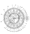
図1は、本発明による日付機構を含む時計ムーブメントの上面図である。全体参照番号1によってその全体をここに示す時計装置がプレート2に取り付けられる。本発明による日付機構は、下側日付リング6とそれに重ね合わされた上側日付リング4を主に含む。上側リング4は、16個のセクターを含み、下側リング6は、17個のセクターを含む。図1を検討して分かる通り、また図4、5を検討するとさらに良く分かる通り、上側リング4は、その15個のセクターで、「17」から「31」のマークを有し、最後のセクターには開いたまたは透明の開口部8が設けられる。下側リング6は、その16個のセクターで、「1」から「16」のマークを含み、最後のセクターにはマークはない。
FIG. 1 is a top view of a timepiece movement including a date mechanism according to the present invention. The timepiece device shown here in its entirety by the
上側日付リング4の内側周囲は、規則的に離隔された歯の連続から形成される内歯を含む。本発明を記述する目的で、また本発明をより良く理解できるように、この1つの内歯が、2段の、それぞれ上側内歯と下側内歯から形成され、それぞれ10と12でここに示すそれらの歯が重ね合わされ、上側内歯の1つの場所14と、下側内歯の1つの場所16には歯がないものとする(図4参照)。
The inner circumference of the
同様に、下側日付リング6の内側周囲は、規則的に離隔された歯の連続から、それぞれが成る2つの周囲内歯を含み、これらの周囲内歯は、2段の、それぞれ上側列と下側列に沿って延び、上側列の歯18は、下側列の歯20に対して互い違いになっている(図5)。以上と同じ理由により、下側列の内歯が、2段の、下側内歯と付加内歯から形成され、それぞれ20と22でここに示すそれらの歯が重ね合わされるものとする。上側内歯の1つの場所24と、下側内歯の1つの場所26には歯がない。
Similarly, the inner periphery of the
図1から3を参照して分かる通り、本発明の日付機構は、日付駆動ホィール28を含み、それが24時間毎に1回転し、上側リング4の上側内歯と、前記下側リング6の下側内歯の歯10と20に作用することによって、日付リング4、6を駆動させる。上側リング4と下側リング6の、それぞれの上側内歯と下側内歯に対する駆動歯28の位置は、これらのリングの一方が、その自由位置(上側リング4では開口部8、また下側リング6ではマークのないセクター)が、時計ムーブメント1の表示場所30にきたとき(文字板の開口部は、数字「16」の位置を占めることになるが、これは取り除かれるものとする)、駆動ホィール28は、上側リング4の上側内歯、または下側リング6の下側内歯の歯のないところ、それぞれ14、26に向いている。
As can be seen with reference to FIGS. 1 to 3, the date mechanism of the present invention includes a
本発明による日付機構はまた、その日付機構によってもたらされた表示を迅速に変更する訂正デバイスも含む。本発明の好ましい実施形態によると、この訂正デバイスは、滑動小歯車32を含む。この滑動小歯車32は、使用者によって訂正ステム33で始動させられ、前記上側リング4の下側内歯と、前記下側リング6の上側内歯との歯12、18に作用することによって、日付リング4、6を駆動する。上側リング4と下側リング6の下側内歯と上側内歯それぞれに対する、滑動小歯車32の位置は、リングの一方がその自由位置を、時計ムーブメントの表示場所30に有する時、滑動小歯車32が、上側リング4の下側内歯または下側リング6の上側内歯の歯のないところ、それぞれ16または24に向き合う。
The date mechanism according to the present invention also includes a correction device that quickly changes the display provided by the date mechanism. According to a preferred embodiment of the present invention, the correction device includes a sliding
ジャンパ効果停止デバイス34は、2つのジャンパ36、38を含み、それぞれ、上側リング4の上側内歯と下側内歯の歯10、12、ならびに下側リング6の下側内歯と付加内歯の歯20、22と協働する。従来技術では、各日付リングそれぞれの内歯の1つの場所に歯がないという事実から、ジャンパが、各リングの連続した3つの歯と協働して、歯のないところの通過中も前記リングの適切な位置決めを保証しなければならなかったが、それとは異なり、本発明によるジャンパ36、38は、所与のリングの内歯の一方または他方の直接連続した2つの歯の間に絶え間なく収容され、それによって、歯のないところの通過中でも、該当日付リングと噛み合ったままとなる。
The jumper
日付リング4、6はそれぞれ、それらの外周に、限界停止部、それぞれ40、42を有する。図4、5が、この配置を詳しく示す。限界停止部40は、上側日付リング4の平面に垂直に延び、限界停止部42は、下側日付リング6の外周の外側径方向に延びる。
The date rings 4, 6 each have a limit stop, 40, 42, respectively, on their outer periphery. Figures 4 and 5 illustrate this arrangement in detail. The
図1から3に示す状態で、上側日付リング4は、その開口部8を表示場所30で、同時に、その歯のないところ14、16が、それぞれ駆動ホィール28と滑動小歯車32に向いている。明らかに、歯のないところ14、16が上側リング4の休止位置を決め、そこでは、駆動ホィール28も滑動小歯車32も前記上側日付リング4に作用することはできない。したがって駆動歯車28は、下側リング6しか駆動せず、下側リング6は、連続的に、マーク「11」、「12」、...「15」、最後に「16」を現す状態にもたらされて、ここに示す位置に到達する。マーク「16」が現れた瞬間、限界停止部42は、限界停止部40と当接する。この瞬間、駆動ホィール28によって下側リング6に伝えられる前進中、上側リング4も駆動され、それによって開口部8が表示場所30から消えて、上側リング4のマーク「17」に道を譲る。この瞬間、駆動ホィール28と滑動小歯車32それぞれに向き合っている歯のないところを有するのは下側リング6である。上側リング4についても同様に、下側リング6の歯のないところ24、26が、前記リング6の休止位置を決め、そこでは駆動ホィール28も滑動小歯車32も、前記下側リング6に作用することができない。このように駆動ホィール28の回転毎に、上側リング4だけが1段前進し、連続的にマーク「17」、「18」、...「30」、「31」が現れるようにする。マーク「31」が表示されると、2つの限界停止部40と42の間の状態は、以上に述べたことの逆となり、即ち、日付リング4の限界停止部40は、下側日付リング6の限界停止部42に当接し、同時に、日付リング4の前進中、日付リング6を前進するようにし、それによってマーク「1」が開口部8の下、表示場所30に現れる。上側リング4が進まされ、下側リング6が休止する間中、表示場所30に面しているのは、下側リング6のマークのないセクターであるが、これは何の影響も及ぼさず、それは、この場合、開口部8が表示場所30にまったく来ておらず、したがって下側リング6を見えるようにはしていないからである。次いで、下側リング6の16個のマークが連続的に行進され、図1から3に示す状態に戻る。するとこのサイクルが再度開始する。
In the state shown in FIGS. 1 to 3, the
言うまでもなく、2つの上側日付リング4と下側日付リング6の相対的な動きは、駆動ホィール28によってではなく、使用者によって訂正ステム33から始動される滑動小歯車32によって駆動される場合も、同じとなる。その場合、2つのリング4、6は、より素早く簡単に回転して、日付機構によってもたらされる表示を使用者が素早く訂正することを可能にする。想起される通り、滑動小歯車32の位置は、上側リング4がその自由位置を表示場所30に有する時、滑動小歯車32が、上側リング4の下側内歯の歯のないところ16に向き合い、また下側リング6がその自由位置を表示場所30に有する時、滑動小歯車32が、下側リング6の上側内歯の歯のないところ24の向かい側に来る。これも想起される通り、滑動小歯車32は、それが使用者によって訂正ステム33で始動される時、日付リングの内歯としか噛み合わない。日付機構の通常動作中、滑動小歯車32は、日付リング4、6とは離れた位置を占める。最後に、承知の通り、駆動ホィール28は、日付リング4、6を、ある種の弾性を有するフィンガを介して駆動し、それによって、リング4または6の一方が滑動小歯車32によって駆動される時、そのフィンガは、それを通過している歯の前から消え、前記歯とその後続の歯によって形成される空洞内に入る。
Needless to say, the relative movement of the two upper date rings 4 and the
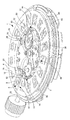
図7は、本発明による日付機構が備えられた時計ムーブメント1の分解図である。このムーブメント1が含むプレート2は、回転時に、2つの下側日付リング6と上側日付リング4を支持し、案内する。プレート2の中心に、従来の形で時針車軸44が立ち、その上に時針車46が係合される。ブリッジ48が担持する停止デバイス34には、その2つのジャンパ36、38が設けられ、それぞれが上側日付リング4と下側日付リング6に対して作用する。駆動ホィール28は駆動されるホィール50を含み、時針車46によって、図示しない減速ホィールを介して駆動されて、24時間毎に完全に1回転する。2つのフィンガ52、54は、例えば溶接によってホィール50上に固定される。これらの2つのフィンガ52、54は、前記上側リング4の上側内歯と、前記下側リング6の下側内歯に作用することによって、それぞれ上側日付リング4と下側日付リング6を駆動させる。上側リング4の上側内歯の歯のないところ14が、駆動ホィール28に向き合って位置する場合、駆動ホィール28は、前記上側リング4に対して影響を与えず、そのフィンガ54を介して、下側日付リング6を、1日に1段ずつ駆動する。逆に、下側日付リング6の下側内歯の歯のないところ26が駆動ホィール28に向き合って位置する場合、フィンガ54は、前記下側リング6の歯20と噛み合うことができず、上側リング4だけが1日に1段ずつ前進する。
FIG. 7 is an exploded view of the
駆動ホィール28は、ブリッジ48の軸56に自由に取り付けられる。同様に、滑動小歯車32は、軸58を介してブリッジ48に取り付けられる。中間ホィール60、62と、小歯車64を含む連鎖によって、前記滑動小歯車32が訂正ステム33に連結される。最後に、本発明による日付機構は、ネジ68を使用して固定された保持プレート66によって、プレート2に軸方向に保持される。
The
図8は、上側日付リング4と下側日付リング6の内歯の、拡大概念図である。この図を検討して分かる通り、上側日付リング4は、数字1、2、...15、16によって識別される16個の歯を含み、下側日付リング6は、数字1、2、...16、17によって識別される17個の歯を含む。上側リング4は、このように16の区画を含み、下側リングは17の区画を含む。
FIG. 8 is an enlarged conceptual diagram of the internal teeth of the
上側日付リング4は、2段の内歯を含み、それぞれ10、12として示すそれらの歯は重ね合わされ、実線の円によってそれぞれが識別される上側内歯の1つの場所14と、下側内歯の1つの場所16には歯がない。
The
上側日付リング6も、2段の内歯を含み、それぞれ18、20として示すそれらの歯は互い違いに合わされ、実線の円によってそれぞれが識別される上側内歯の1つの場所24と、下側内歯の1つの場所26には歯がない。下側日付リング6は、追加の内歯も含み、その歯22は、下側内歯の歯20と一致する。
The
上側日付リング4と下側日付リング6の内歯に向き合っている駆動ホィール28の位置と、滑動小歯車32の位置が、それぞれ直線のセグメントA‐AとB‐Bによって識別されている。最後に、2つのジャンパ36、38が、2つの長方形によって表され、それらは同じ参照番号を担持する。図面を検討して分かる通り、2つのジャンパ36と38の高さは、前記ジャンパが協働する相手の、上側日付リング4の上側内歯と下側内歯の厚み、ならびに下側日付リング6の下側内歯と追加内歯の厚みに等しい。
The position of the
図8に示す状態で、上側日付リング4は、それぞれ駆動ホィール28と滑動小歯車32に向き合っている2つの歯のないところ14、16がある。この位置は、上側リング4がその開口部8をムーブメントの表示場所30に有し、下側リング6によって支承される数字「16」を現す状態に対応する。マーク「16」が現れた瞬間、下側リング6の限界停止部42は、上側リング4の限界停止部40に当接する。このように、下側リング6が、駆動ホィール28によって前進されると、上側リング4も駆動される。そうなると、歯のないところ24と26を、それぞれ駆動ホィール28と滑動小歯車32と向き合っているのは、下側リング6であり、上側リング4の歯のないところ14と16は、前進を一段完了する。
In the state shown in FIG. 8, the
以上で既に述べた通り、2つのジャンパ36、38の高さは、歯10、12と20、22の厚みと実質的に等しく、それによって、歯のないところの通過中、前記ジャンパは、上側円盤と下側円盤の内歯の直接連続した2つの歯の間に依然係合したままとなって、前記円盤の適切な位置決めを保証する。
As already mentioned above, the height of the two
言うまでもなく、本発明は、以上に述べた実施形態に限定されず、本発明の範囲から逸脱せずに、当業者は、様々な簡単な修正および変形形態を想定することができる。特に、上側日付リングが、17個のセクターを含み、下側日付リングが、16個しか有さないことも可能である。 Needless to say, the present invention is not limited to the embodiments described above, and various simple modifications and variations can be envisaged by those skilled in the art without departing from the scope of the present invention. In particular, it is possible that the upper date ring includes 17 sectors and the lower date ring has only 16 sectors.
1 時計ムーブメント、2 プレート、4、6 上下側日付リング、8 開口部、10、12 上側日付リングの上下歯列、14、16 上側日付リングの上下歯列の歯のないところ、18、20 下側日付リングの上下歯列、22 下側日付リングの追加の歯列の歯、24、26 下側日付リングの上下歯列の歯のないところ、28 駆動ホィール、30 表示場所、32 滑動小歯車、33 訂正ステム、34 ジャンパ効果停止デバイス、36、38 ジャンパ、40、42 限界停止部、44 時針車軸、46 時針車、48 ブリッジ、50 駆動ホィールのホィール、52、54 駆動ホィール28のフィンガ、60、62 中間ホィール、64 小歯車、66 保持プレート、68 ネジ
1 Clock movement, 2 plates, 4, 6 Upper and lower date rings, 8 Opening, 10, 12 Upper date ring upper and lower teeth, 14, 16 Upper date ring upper and lower teeth without teeth, 18, 20 Lower Upper date row of the side date ring, 22 Additional teeth of the lower date ring, 24, 26 No teeth of the upper and lower rows of the lower date ring, 28 Drive wheel, 30 Display location, 32 Sliding small gear , 33 Correction stem, 34 Jumper effect stop device, 36, 38 Jumper, 40, 42 Limit stop, 44 hour hand axle, 46 hour hand wheel, 48 bridge, 50 drive wheel wheel, 52, 54
Claims (5)
Applications Claiming Priority (1)
| Application Number | Priority Date | Filing Date | Title |
|---|---|---|---|
| EP03027146A EP1536299B1 (en) | 2003-11-26 | 2003-11-26 | Calendar mechanism for a watch comprising two superposed date annuli |
Publications (2)
| Publication Number | Publication Date |
|---|---|
| JP2005156562A JP2005156562A (en) | 2005-06-16 |
| JP4523835B2 true JP4523835B2 (en) | 2010-08-11 |
Family
ID=34442880
Family Applications (1)
| Application Number | Title | Priority Date | Filing Date |
|---|---|---|---|
| JP2004341913A Active JP4523835B2 (en) | 2003-11-26 | 2004-11-26 | Watch having a date mechanism with two date rings superimposed |
Country Status (9)
| Country | Link |
|---|---|
| US (1) | US6925032B2 (en) |
| EP (1) | EP1536299B1 (en) |
| JP (1) | JP4523835B2 (en) |
| KR (1) | KR101067067B1 (en) |
| CN (1) | CN1621975B (en) |
| DE (1) | DE60332637D1 (en) |
| HK (1) | HK1077883A1 (en) |
| SG (1) | SG112097A1 (en) |
| TW (1) | TW200519553A (en) |
Families Citing this family (13)
| Publication number | Priority date | Publication date | Assignee | Title |
|---|---|---|---|---|
| CN101151583B (en) * | 2005-03-30 | 2010-05-19 | 西铁城控股株式会社 | Display device and calendar device of timepiece |
| US20070047390A1 (en) * | 2005-08-29 | 2007-03-01 | Shigeo Suzuki | Timepiece with calendar mechanism indicating date by plurality of date indicators |
| JP2007121077A (en) * | 2005-10-27 | 2007-05-17 | Casio Comput Co Ltd | Timepiece with calendar function, assembly method of timepiece with calendar function, and radio-controlled timepiece with calendar function |
| FR2893726B1 (en) * | 2005-11-21 | 2008-01-18 | Sylvain Boileau | QUANTIME DISPLAY MECHANISM FOR WATCHES |
| DE602006007855D1 (en) * | 2006-09-26 | 2009-08-27 | Eta Sa Mft Horlogere Suisse | Movement comprising a mounting plate for a display ring |
| JP4595977B2 (en) * | 2007-09-20 | 2010-12-08 | カシオ計算機株式会社 | Dial and electronic equipment |
| EP2141556B1 (en) * | 2008-07-03 | 2012-06-27 | ETA SA Manufacture Horlogère Suisse | Calendar mechanism for a timepiece |
| SG159457A1 (en) * | 2008-08-11 | 2010-03-30 | Blancpain Sa | Large date calendar day mechanism for a timepiece |
| EP2434354B1 (en) | 2010-09-27 | 2012-12-12 | ETA SA Manufacture Horlogère Suisse | Large display with aperture for a clock piece |
| JP5853504B2 (en) * | 2011-08-31 | 2016-02-09 | セイコーエプソン株式会社 | Dial assembly and clock |
| JP6015207B2 (en) * | 2012-07-31 | 2016-10-26 | カシオ計算機株式会社 | Information display device and analog electronic timepiece |
| EP2945026B1 (en) * | 2014-05-14 | 2018-01-03 | ETA SA Manufacture Horlogère Suisse | Quick correction mechanism of a timepiece |
| HK1252182A2 (en) * | 2018-07-06 | 2019-05-17 | Pengelly Co Ltd | Watch with geometric codes |
Citations (3)
| Publication number | Priority date | Publication date | Assignee | Title |
|---|---|---|---|---|
| GB957031A (en) * | 1962-01-13 | 1964-05-06 | Karl Diehl Dipl Ing | Clock with date indicator |
| DE19845539A1 (en) * | 1998-10-02 | 2000-04-06 | Fortis Ag Grenchen | Wristwatch with large date display has indexing member which increments disc by two or more indexing teeth |
| JP2005134265A (en) * | 2003-10-31 | 2005-05-26 | Citizen Watch Co Ltd | Calendar mechanism |
Family Cites Families (10)
| Publication number | Priority date | Publication date | Assignee | Title |
|---|---|---|---|---|
| DE2036464C3 (en) * | 1970-07-22 | 1974-10-03 | Gebrueder Junghans Gmbh, 7230 Schramberg | Clock with date display |
| CH624534GA3 (en) * | 1979-04-04 | 1981-08-14 | ||
| CH660941GA3 (en) * | 1985-06-11 | 1987-06-30 | Fred Murten Bandi | Counting and display device with window, especially for wrist watch or other timepiece calendar, with analogue display |
| CN2064074U (en) * | 1989-08-25 | 1990-10-17 | 天津手表厂 | Calendar mechanism of wristwatch |
| JP3081992B2 (en) * | 1996-10-02 | 2000-08-28 | セイコーインスツルメンツ株式会社 | Wristwatch with calendar |
| JP3939073B2 (en) * | 2000-03-31 | 2007-06-27 | セイコーインスツル株式会社 | Clock with calendar mechanism |
| DE1152303T1 (en) * | 2000-05-05 | 2002-10-02 | Rolex Montres | Watch with winding mechanism and with correction mechanism for at least two indicating organs |
| TW493113B (en) * | 2000-08-23 | 2002-07-01 | Ebauchesfabrik Eta Ag | Electronic watch with a large date aperture |
| SG102647A1 (en) * | 2000-12-22 | 2004-03-26 | Ebauchesfabrik Eta Ag | Timepiece provided with a date having a large aperture |
| EP1316858B1 (en) * | 2001-11-30 | 2008-01-23 | Rolex Sa | Date mechanism for timepiece |
-
2003
- 2003-11-26 DE DE60332637T patent/DE60332637D1/en not_active Expired - Lifetime
- 2003-11-26 EP EP03027146A patent/EP1536299B1/en not_active Expired - Lifetime
-
2004
- 2004-11-12 SG SG200407205A patent/SG112097A1/en unknown
- 2004-11-17 TW TW093135279A patent/TW200519553A/en unknown
- 2004-11-22 US US10/992,695 patent/US6925032B2/en active Active
- 2004-11-24 KR KR1020040096652A patent/KR101067067B1/en not_active IP Right Cessation
- 2004-11-25 CN CN2004100917337A patent/CN1621975B/en active Active
- 2004-11-26 JP JP2004341913A patent/JP4523835B2/en active Active
-
2005
- 2005-11-07 HK HK05109890.7A patent/HK1077883A1/en unknown
Patent Citations (3)
| Publication number | Priority date | Publication date | Assignee | Title |
|---|---|---|---|---|
| GB957031A (en) * | 1962-01-13 | 1964-05-06 | Karl Diehl Dipl Ing | Clock with date indicator |
| DE19845539A1 (en) * | 1998-10-02 | 2000-04-06 | Fortis Ag Grenchen | Wristwatch with large date display has indexing member which increments disc by two or more indexing teeth |
| JP2005134265A (en) * | 2003-10-31 | 2005-05-26 | Citizen Watch Co Ltd | Calendar mechanism |
Also Published As
| Publication number | Publication date |
|---|---|
| KR20050050554A (en) | 2005-05-31 |
| US20050111303A1 (en) | 2005-05-26 |
| JP2005156562A (en) | 2005-06-16 |
| SG112097A1 (en) | 2005-06-29 |
| TW200519553A (en) | 2005-06-16 |
| HK1077883A1 (en) | 2006-02-24 |
| EP1536299B1 (en) | 2010-05-19 |
| CN1621975B (en) | 2012-11-07 |
| KR101067067B1 (en) | 2011-09-22 |
| EP1536299A1 (en) | 2005-06-01 |
| CN1621975A (en) | 2005-06-01 |
| DE60332637D1 (en) | 2010-07-01 |
| US6925032B2 (en) | 2005-08-02 |
Similar Documents
| Publication | Publication Date | Title |
|---|---|---|
| JP4523835B2 (en) | Watch having a date mechanism with two date rings superimposed | |
| JP4307613B2 (en) | Date mechanism for clock movement | |
| JP3316602B2 (en) | Clock with world time display | |
| EP0230878B1 (en) | Clockwork movement | |
| JP5918502B2 (en) | clock | |
| JP4754334B2 (en) | Annual calendar mechanism for clock | |
| JP4276461B2 (en) | A watch with an elongated case | |
| JP4242635B2 (en) | Method of forming a date indicator actuated by a watch movement and mechanism for implementing the method | |
| JP4537183B2 (en) | Watch having a date mechanism with two date rings superimposed | |
| US20080094941A1 (en) | Annual calendar mechanism for a timepiece | |
| US6912180B2 (en) | Timepiece with calendar | |
| JP2005539213A (en) | A timepiece that displays the date of the month | |
| JP4626970B2 (en) | Multifunction watch with multiple fan-shaped wheel train layouts | |
| JP4567666B2 (en) | Date display mechanism for wristwatch movement | |
| KR101279714B1 (en) | Time piece provided with a date dial | |
| US20030090963A1 (en) | Device for winding and setting the time of a timepiece such as a date-watch including a date disc | |
| JPWO2006064556A1 (en) | Multifunction watch that can realize multiple movement layouts | |
| JP7041219B2 (en) | Timekeeper with morning and afternoon display means | |
| JP2612234B2 (en) | Timepiece with rotary display | |
| US3597917A (en) | Day-indicating system of a calendar watch | |
| JP2004144754A (en) | Timepiece containing analog type time-indicating means concerning means indicating daytime/night or am/pm | |
| JP7475117B2 (en) | Clock and calendar device | |
| US20220197220A1 (en) | Multiple jump timepiece display mechanism | |
| CH696986A5 (en) | Retrograde or continuous display device for e.g. wristwatch, has transparent parts through which mark corresponding to index zone appears when index is indicated, where indexes in one scale zone are not aligned on indexes in other zones | |
| US20210397132A1 (en) | Display mechanism with a single aperture |
Legal Events
| Date | Code | Title | Description |
|---|---|---|---|
| A621 | Written request for application examination |
Free format text: JAPANESE INTERMEDIATE CODE: A621 Effective date: 20071109 |
|
| A131 | Notification of reasons for refusal |
Free format text: JAPANESE INTERMEDIATE CODE: A131 Effective date: 20100119 |
|
| A521 | Request for written amendment filed |
Free format text: JAPANESE INTERMEDIATE CODE: A523 Effective date: 20100127 |
|
| TRDD | Decision of grant or rejection written | ||
| A01 | Written decision to grant a patent or to grant a registration (utility model) |
Free format text: JAPANESE INTERMEDIATE CODE: A01 Effective date: 20100518 |
|
| A01 | Written decision to grant a patent or to grant a registration (utility model) |
Free format text: JAPANESE INTERMEDIATE CODE: A01 |
|
| A61 | First payment of annual fees (during grant procedure) |
Free format text: JAPANESE INTERMEDIATE CODE: A61 Effective date: 20100528 |
|
| R150 | Certificate of patent or registration of utility model |
Ref document number: 4523835 Country of ref document: JP Free format text: JAPANESE INTERMEDIATE CODE: R150 Free format text: JAPANESE INTERMEDIATE CODE: R150 |
|
| FPAY | Renewal fee payment (event date is renewal date of database) |
Free format text: PAYMENT UNTIL: 20130604 Year of fee payment: 3 |
|
| R250 | Receipt of annual fees |
Free format text: JAPANESE INTERMEDIATE CODE: R250 |
|
| R250 | Receipt of annual fees |
Free format text: JAPANESE INTERMEDIATE CODE: R250 |
|
| R250 | Receipt of annual fees |
Free format text: JAPANESE INTERMEDIATE CODE: R250 |
|
| R250 | Receipt of annual fees |
Free format text: JAPANESE INTERMEDIATE CODE: R250 |
|
| R250 | Receipt of annual fees |
Free format text: JAPANESE INTERMEDIATE CODE: R250 |
|
| R250 | Receipt of annual fees |
Free format text: JAPANESE INTERMEDIATE CODE: R250 |
|
| R250 | Receipt of annual fees |
Free format text: JAPANESE INTERMEDIATE CODE: R250 |
|
| R250 | Receipt of annual fees |
Free format text: JAPANESE INTERMEDIATE CODE: R250 |
|
| R250 | Receipt of annual fees |
Free format text: JAPANESE INTERMEDIATE CODE: R250 |
|
| R250 | Receipt of annual fees |
Free format text: JAPANESE INTERMEDIATE CODE: R250 |