JP4523228B2 - Motion device for supporting and programmably driving an end element in a machine or instrument - Google Patents
Motion device for supporting and programmably driving an end element in a machine or instrument Download PDFInfo
- Publication number
- JP4523228B2 JP4523228B2 JP2002565749A JP2002565749A JP4523228B2 JP 4523228 B2 JP4523228 B2 JP 4523228B2 JP 2002565749 A JP2002565749 A JP 2002565749A JP 2002565749 A JP2002565749 A JP 2002565749A JP 4523228 B2 JP4523228 B2 JP 4523228B2
- Authority
- JP
- Japan
- Prior art keywords
- platform
- joint
- axis
- support
- drive
- Prior art date
- Legal status (The legal status is an assumption and is not a legal conclusion. Google has not performed a legal analysis and makes no representation as to the accuracy of the status listed.)
- Expired - Fee Related
Links
Images


Classifications
-
- B—PERFORMING OPERATIONS; TRANSPORTING
- B25—HAND TOOLS; PORTABLE POWER-DRIVEN TOOLS; MANIPULATORS
- B25J—MANIPULATORS; CHAMBERS PROVIDED WITH MANIPULATION DEVICES
- B25J17/00—Joints
- B25J17/02—Wrist joints
- B25J17/0258—Two-dimensional joints
- B25J17/0266—Two-dimensional joints comprising more than two actuating or connecting rods
-
- B—PERFORMING OPERATIONS; TRANSPORTING
- B25—HAND TOOLS; PORTABLE POWER-DRIVEN TOOLS; MANIPULATORS
- B25J—MANIPULATORS; CHAMBERS PROVIDED WITH MANIPULATION DEVICES
- B25J17/00—Joints
- B25J17/02—Wrist joints
-
- B—PERFORMING OPERATIONS; TRANSPORTING
- B23—MACHINE TOOLS; METAL-WORKING NOT OTHERWISE PROVIDED FOR
- B23Q—DETAILS, COMPONENTS, OR ACCESSORIES FOR MACHINE TOOLS, e.g. ARRANGEMENTS FOR COPYING OR CONTROLLING; MACHINE TOOLS IN GENERAL CHARACTERISED BY THE CONSTRUCTION OF PARTICULAR DETAILS OR COMPONENTS; COMBINATIONS OR ASSOCIATIONS OF METAL-WORKING MACHINES, NOT DIRECTED TO A PARTICULAR RESULT
- B23Q1/00—Members which are comprised in the general build-up of a form of machine, particularly relatively large fixed members
- B23Q1/25—Movable or adjustable work or tool supports
- B23Q1/44—Movable or adjustable work or tool supports using particular mechanisms
- B23Q1/48—Movable or adjustable work or tool supports using particular mechanisms with sliding pairs and rotating pairs
- B23Q1/4852—Movable or adjustable work or tool supports using particular mechanisms with sliding pairs and rotating pairs a single sliding pair followed perpendicularly by a single rotating pair
-
- B—PERFORMING OPERATIONS; TRANSPORTING
- B23—MACHINE TOOLS; METAL-WORKING NOT OTHERWISE PROVIDED FOR
- B23Q—DETAILS, COMPONENTS, OR ACCESSORIES FOR MACHINE TOOLS, e.g. ARRANGEMENTS FOR COPYING OR CONTROLLING; MACHINE TOOLS IN GENERAL CHARACTERISED BY THE CONSTRUCTION OF PARTICULAR DETAILS OR COMPONENTS; COMBINATIONS OR ASSOCIATIONS OF METAL-WORKING MACHINES, NOT DIRECTED TO A PARTICULAR RESULT
- B23Q1/00—Members which are comprised in the general build-up of a form of machine, particularly relatively large fixed members
- B23Q1/25—Movable or adjustable work or tool supports
- B23Q1/44—Movable or adjustable work or tool supports using particular mechanisms
- B23Q1/50—Movable or adjustable work or tool supports using particular mechanisms with rotating pairs only, the rotating pairs being the first two elements of the mechanism
- B23Q1/54—Movable or adjustable work or tool supports using particular mechanisms with rotating pairs only, the rotating pairs being the first two elements of the mechanism two rotating pairs only
- B23Q1/545—Movable or adjustable work or tool supports using particular mechanisms with rotating pairs only, the rotating pairs being the first two elements of the mechanism two rotating pairs only comprising spherical surfaces
- B23Q1/5462—Movable or adjustable work or tool supports using particular mechanisms with rotating pairs only, the rotating pairs being the first two elements of the mechanism two rotating pairs only comprising spherical surfaces with one supplementary sliding pair
-
- B—PERFORMING OPERATIONS; TRANSPORTING
- B25—HAND TOOLS; PORTABLE POWER-DRIVEN TOOLS; MANIPULATORS
- B25J—MANIPULATORS; CHAMBERS PROVIDED WITH MANIPULATION DEVICES
- B25J9/00—Programme-controlled manipulators
- B25J9/003—Programme-controlled manipulators having parallel kinematics
- B25J9/0033—Programme-controlled manipulators having parallel kinematics with kinematics chains having a prismatic joint at the base
- B25J9/0039—Programme-controlled manipulators having parallel kinematics with kinematics chains having a prismatic joint at the base with kinematics chains of the type prismatic-spherical-spherical
-
- B—PERFORMING OPERATIONS; TRANSPORTING
- B25—HAND TOOLS; PORTABLE POWER-DRIVEN TOOLS; MANIPULATORS
- B25J—MANIPULATORS; CHAMBERS PROVIDED WITH MANIPULATION DEVICES
- B25J9/00—Programme-controlled manipulators
- B25J9/003—Programme-controlled manipulators having parallel kinematics
- B25J9/0072—Programme-controlled manipulators having parallel kinematics of the hybrid type, i.e. having different kinematics chains
-
- Y—GENERAL TAGGING OF NEW TECHNOLOGICAL DEVELOPMENTS; GENERAL TAGGING OF CROSS-SECTIONAL TECHNOLOGIES SPANNING OVER SEVERAL SECTIONS OF THE IPC; TECHNICAL SUBJECTS COVERED BY FORMER USPC CROSS-REFERENCE ART COLLECTIONS [XRACs] AND DIGESTS
- Y10—TECHNICAL SUBJECTS COVERED BY FORMER USPC
- Y10T—TECHNICAL SUBJECTS COVERED BY FORMER US CLASSIFICATION
- Y10T409/00—Gear cutting, milling, or planing
- Y10T409/30—Milling
- Y10T409/306664—Milling including means to infeed rotary cutter toward work
- Y10T409/307672—Angularly adjustable cutter head
-
- Y—GENERAL TAGGING OF NEW TECHNOLOGICAL DEVELOPMENTS; GENERAL TAGGING OF CROSS-SECTIONAL TECHNOLOGIES SPANNING OVER SEVERAL SECTIONS OF THE IPC; TECHNICAL SUBJECTS COVERED BY FORMER USPC CROSS-REFERENCE ART COLLECTIONS [XRACs] AND DIGESTS
- Y10—TECHNICAL SUBJECTS COVERED BY FORMER USPC
- Y10T—TECHNICAL SUBJECTS COVERED BY FORMER US CLASSIFICATION
- Y10T409/00—Gear cutting, milling, or planing
- Y10T409/30—Milling
- Y10T409/309576—Machine frame
-
- Y—GENERAL TAGGING OF NEW TECHNOLOGICAL DEVELOPMENTS; GENERAL TAGGING OF CROSS-SECTIONAL TECHNOLOGIES SPANNING OVER SEVERAL SECTIONS OF THE IPC; TECHNICAL SUBJECTS COVERED BY FORMER USPC CROSS-REFERENCE ART COLLECTIONS [XRACs] AND DIGESTS
- Y10—TECHNICAL SUBJECTS COVERED BY FORMER USPC
- Y10T—TECHNICAL SUBJECTS COVERED BY FORMER US CLASSIFICATION
- Y10T74/00—Machine element or mechanism
- Y10T74/20—Control lever and linkage systems
- Y10T74/20207—Multiple controlling elements for single controlled element
- Y10T74/20305—Robotic arm
- Y10T74/20329—Joint between elements
- Y10T74/20335—Wrist
Landscapes
- Engineering & Computer Science (AREA)
- Mechanical Engineering (AREA)
- Robotics (AREA)
- Manipulator (AREA)
- Machine Tool Units (AREA)
- Transmission Devices (AREA)
- Pivots And Pivotal Connections (AREA)
- Prostheses (AREA)
- Organic Low-Molecular-Weight Compounds And Preparation Thereof (AREA)
Description
本発明は、前もって決められた作業空間の範囲内でプログラム可能で高精度制御された状態の移動及び/又は回転において、端部要素を支持及び駆動するための運動デバイス(装置)の技術分野に関する。 The present invention relates to the technical field of motion devices for supporting and driving end elements in movement and / or rotation in a programmable and precisely controlled state within a predetermined working space. .
端部要素は、デバイスがマシニングセンタ、又は例えば、輸送機械、組み立てロボット、梱包機械、計測計器、及び医療機器等における、グリッパー(把持)工具、組み立て(アセンブリ)工具、計測センサ、外力戻り式ジョイスティック用使用者インターフェース(接続部)、アンテナ、カメラホルダ(保持器)等、あるいは高精度な位置決め又は移動及び/又は高度な運動性能が必要な任意のデバイスに組み込まれる場合に、機械加工工具(スピンドル、レーザー、ウォータジェット、放電加工ツール等)又は工作物キャリア(運搬部)であって良い。 End elements for machining centers or gripper tools, assembly tools, measurement sensors, external force return joysticks in devices such as transport centers, assembly robots, packaging machines, measuring instruments and medical devices Machining tools (spindles, etc.) when incorporated in user interfaces (connections), antennas, camera holders (cages), etc., or any device that requires high precision positioning or movement and / or high kinematic performance Laser, water jet, electric discharge machining tool, etc.) or workpiece carrier (conveyance section).
この分野において多くの用途が存在しており、それらはグリッパーを必要とし、グリッパーの角度的位置決めは、そのベース(台)に平行な軸線周りで制御可能である。これは例えば、複雑な工作物の機械加工又は高い美的品質の工作物の研磨(又はつや出し)に適用される。 There are many applications in this field, they require a gripper, and the angular positioning of the gripper can be controlled around an axis parallel to its base. This applies, for example, to the machining of complex workpieces or the polishing (or polishing) of high aesthetic quality workpieces.
特別には、高い処理能力で小型で複雑な工作物の製造のためには、高い機械加工速度が可能なだけではなく、更に加工間の時間を最短にするために、非常に早い工具の交換が可能である機械を有することが必要である。 Specially, for the production of small and complex workpieces with high throughput, not only high machining speeds are possible, but also very fast tool changes in order to minimize the time between machining It is necessary to have a machine that can.
運動機械に平行なそれらの高度な運動性能(低い運動質量及び高い剛性)により、工具はこれらの2つの制約要素を満足させ得る。 Due to their high kinematic performance (low kinematic mass and high stiffness) parallel to the kinematic machine, the tool can satisfy these two constraints.
しかし、市販に存在する平行な機械加工工具及びロボットの主な欠点は、それらの比較的小さな作業体積及び非常に制限された角度的可動性にある。 However, the main drawback of commercially available parallel machining tools and robots is their relatively small working volume and very limited angular mobility.
非常に高い性能構造は、グリッパー部材等の端部要素の駆動に、より特別に適用されており、例えば、欧州特許EP0250470及び米国特許第4,976,582号に開示される。この構造において3つの基本的な自由度が、固定支持部に配設されたアクチュエータを使用して平行に制御される一方で、固定支持部に対する可動要素の平行度が保持される。三次元の移動におけるそれの高度な運動性及び可動性の観点において、その様な構造は、高移動速度(1秒当たり3つの移動以上で)での、軽量工作物の移動に特別に良好に適している。その構造の独創性は、運動形態により固定されたグリッパーの角度的位置決めの動きの全てにある。不幸にもその様なデバイス(装置)はそれ自体、一つ以上の回転が必要な用途を満足することが出来ない。 A very high performance structure has been applied more specifically to driving end elements such as gripper members, as disclosed, for example, in European Patent EP0250470 and US Pat. No. 4,976,582. In this structure, three basic degrees of freedom are controlled in parallel using actuators arranged on the fixed support, while the parallelism of the movable element with respect to the fixed support is maintained. In view of its advanced motility and mobility in three-dimensional movement, such a structure is particularly well suited for moving lightweight workpieces at high movement speeds (more than three movements per second). Is suitable. The originality of the structure lies in all the angular positioning movements of the gripper fixed by the movement form. Unfortunately, such a device cannot itself satisfy an application that requires more than one rotation.
更に、国際特許出願WO98/51443及びWO99/32256は、繊細な工作物、特別にはタービン翼、の製造用に設計された機械加工工具におけるフライス盤等の工具の平行な運動制御に関するものが既知である。不幸にも、これらの文献に開示されるデバイスは、工具の角度的動きのみを実現可能であり、その角度的動きは、構造の良好な剛性が維持される場合に非常に小さい(約+−30度)。 Furthermore, the international patent applications WO 98/51443 and WO 99/32256 are known for parallel motion control of tools such as milling machines in machining tools designed for the manufacture of delicate workpieces, in particular turbine blades. is there. Unfortunately, the devices disclosed in these documents can only achieve an angular movement of the tool, which is very small (about +-if the good stiffness of the structure is maintained). 30 degrees).
本発明の目的は、既知のデバイスに比べてより良好に且つより包括的に上記の必要性を満足する、平行運動デバイスを提供することであり、更にそのデバイスは特に、出来る限り大きな体積の作業空間において、端部要素の動きをプログラムすることが可能である一方で、出来る限り高度な作業精度及び速度を提供し、更に該作業体積の範囲内で均一な挙動を保証することである。 The object of the present invention is to provide a parallel motion device that satisfies the above-mentioned needs better and more comprehensively compared to known devices, which device is particularly capable of working as large a volume as possible. While it is possible to program the movement of the end elements in the space, it offers the highest possible working accuracy and speed and further ensures a uniform behavior within the working volume.
結局、本発明は、計器又は機械における端部要素を支持し且つ駆動するための運動デバイスを提供する。該デバイスは、基準平面を形成する固定ベース(1)と、所定の作業空間内で、端部要素(21)を駆動するように配置された支持及び駆動構造と、を具備する。支持及び駆動構造は、作業空間のX軸を形成する唯1つの自由度で移動するためにベース(1)において案内される、少なくとも2つの案内部材(3,4;40,41,42)と、一定の長さの少なくとも2つの剛な脚(7,8;46,47,48)と、端部要素(21)を支持するプラットフォーム(11;50)と、各案内部材(3,4)を脚(7,8)の1つの脚の一方の端部に接続し且つ脚のもう一方の端部をプラットフォーム(11)に接続する、支持・駆動ジョイント装置(5,9,6,10)と、を具備する。支持及び駆動構造は、プラットフォーム(11)に属する、旋回軸の周りで端部要素(21)を旋回させるための付属構造を更に具備しており、それにより、旋回軸を、その前の位置に平行に、X軸に垂直なY方向で変位させる。付属構造は、唯1つの自由度で移動するようにベース(1)上で案内される、付属案内部材(12;16)と、固定された長さの付属の剛な駆動要素(14)と、駆動要素(14)の一方の端部を付属案内部材(12)に接続する、ジョイント(13)と、駆動要素(14)のもう一方の端部とプラットフォーム(11)との間にある移行構造(20,15)であって、移行構造における移行ジョイント(15)を介して、付属案内部材(12)の変位に対応して端部要素(21)に力を伝達する、移行構造(20,15)と、を具備する。移行構造(20,15)の配置及び前記プラットフォーム(11)に対する移行ジョイント(15)の位置は、移行ジョイント(15)における力の方向が、作業空間内の端部要素(21)の全ての位置に関して、移行ジョイント(15)を旋回軸に接続する線に実質的に垂直な位置に保持され、それにより、作業空間内において、端部要素(21)に作用する、トルクは、作業空間内の端部要素の位置に関係なく、実質的に一定である。 Ultimately, the present invention provides a motion device for supporting and driving end elements in a meter or machine. The device includes a fixed base (1) to form a reference plane, in a predetermined work space, comprising the arranged supporting and driving structure to drive the end element (21), the. The support and drive structure has at least two guide members (3, 4; 40, 41, 42) guided in the base (1) to move with only one degree of freedom forming the X axis of the workspace A fixed length of at least two rigid legs (7, 8; 46, 47, 48), a platform (11; 50) for supporting the end element (21), and each guide member (3, 4) Support-drive joint device (5, 9, 6, 10) connecting one end of one leg of the leg (7, 8) and the other end of the leg to the platform (11) And. The support and drive structure further comprises an ancillary structure for pivoting the end element (21) about the pivot axis, belonging to the platform (11), so that the pivot axis is in its previous position. In parallel, it is displaced in the Y direction perpendicular to the X axis. The attachment structure includes an attachment guide member (12; 16) guided on the base (1) so as to move with only one degree of freedom, and an attached rigid drive element (14) of fixed length. Connecting one end of the drive element (14) to the associated guide member (12), the transition between the joint (13) and the other end of the drive element (14) and the platform (11) a structure (20, 15), via a transition joint (15) in the transition structure to transmit force to the end element corresponding to the displacement (21) of the additional guidance member (12), the transition structure (20 15). The arrangement of the transition structure (20, 15) and the position of the transition joint (15) relative to the platform (11) is such that the direction of the force at the transition joint (15) is such that all positions of the end elements (21) in the work space. regard, is held the transition joint (15) in a substantially vertical position to a line connecting the pivot axis, whereby, in the work space, acts on the end element (21), torque, work space Regardless of the position of the end elements, the position is substantially constant .
該付属構造は、少なくとも一つの案内部材を具備しても良く、その案内部材は、前記ベースに対して一つの自由度で動くように案内されており、前記デバイスは前記端部要素の旋回軸線に平行な軸線に沿って前記プラットフォームを動かすための手段を具備可能であり、該手段は該付属構造に組み込まれる。 The attachment structure may comprise at least one guide member, the guide member being guided to move with one degree of freedom relative to the base, the device being a pivot axis of the end element. Means for moving the platform along an axis parallel to the axis, the means being incorporated into the attachment structure.
該付属構造は、旋回ジョイントであっても良い少なくとも一つの中間ジョイントと、前記中間ジョイントにより形成される前記端部要素の1つの自由度を制御する少なくとも一つの剛な接続要素とを具備しても良く、該剛な制御要素は、該中間ジョイントと該支持及び駆動構造の脚の案内部材との間でヒンジ止め可能であり、前記端部要素は前記プラットフォームに剛に固定されており、更に前記中間ジョイントが前記プラットフォーム又は前記端部要素上に旋回可能に設置される剛な要素に設置されることが可能である。 The attachment structure comprises at least one intermediate joint, which may be a pivot joint, and at least one rigid connecting element that controls one degree of freedom of the end element formed by the intermediate joint. The rigid control element can be hinged between the intermediate joint and a guide member of the leg of the support and drive structure, the end element being rigidly fixed to the platform; The intermediate joint can be installed on a rigid element that is pivotally installed on the platform or the end element.
変形形態において、該剛な制御要素は、該中間ジョイントと該支持及び駆動構造の脚の案内部材との間でヒンジ止めされても良く、前記端部要素は前記プラットフォームに旋回可能に設置される。 In a variant, the rigid control element may be hinged between the intermediate joint and a guide member of the leg of the support and drive structure, the end element being pivotally mounted on the platform .
これとは別の変形形態において、該剛な制御要素は前記中間ジョイントと前記プラットフォームとの間でヒンジ止めされており、前記端部要素は該プラットフォームに旋回可能に設置される。 In another variant, the rigid control element is hinged between the intermediate joint and the platform, and the end element is pivotally mounted on the platform.
1つの実施の形態において、前記ジョイントの少なくとも幾つかはボール及びソケットジョイントであり、該支持及び駆動構造は、前記端部要素を三次元において運動可能にするように構成されており、前記作業空間は該案内部材の動きの振幅により決定される体積まで伸張する。 In one embodiment, at least some of the joints are ball and socket joints, and the support and drive structure is configured to allow the end element to move in three dimensions, the working space. Extends to a volume determined by the amplitude of movement of the guide member.
これとは別の実施の形態において、前記作動ジョイントの少なくとも3つは旋回ジョイントであり、前記旋回軸線はお互いに平行であり、作業空間は該基準平面及び前記旋回軸線に垂直な平面に含まれる部分に制限されており、機械又は計器は前記旋回軸線に平行な軸線に沿って動かされるため、及び前記端部要素が作用する、工作物を受容するように作用するために、適当な支持を具備可能である。 In another embodiment, at least three of the actuating joints are pivot joints, the pivot axes are parallel to each other, and the work space is included in the reference plane and a plane perpendicular to the pivot axis. The machine or instrument is moved along an axis parallel to the swivel axis and the end element acts to act to receive the work piece, It can be provided.
本発明のデバイスの種々の実施の形態は、添付の図解的図面を参照して以下で説明される。 Various embodiments of the device of the present invention are described below with reference to the accompanying schematic drawings.
本説明において、用語「作動ジョイント」は、それが取り付けられるデバイス(装置)のオペレーションに必要であって、内部可動性を可能にするジョイントとは異なっていて、例えば、2つのボールとソケットジョイントをその端部において装備する棒(バー)等であって、更に任意の機能性を具備しないそれ自身の軸の周りで回転可能である、ジョイントを指定するために使用される。 In this description, the term “actuating joint” is different from a joint that is necessary for the operation of the device to which it is attached and allows internal mobility, for example two ball and socket joints. Used to designate a joint that is equipped at its end, such as a bar, that can be rotated about its own axis without any functionality.
図面は、支持及び駆動デバイス(装置)を図解的に示しており、そのデバイスは、機械加工工具、計器、ロボット、又は例えば組み立て機械等の作業機械の幾つかの別のタイプのものにおいて使用するのに適する。工作物を移動するための機械において、端部要素は、クロー(爪)又は吸引カップ、又はグリッパー部材の幾つかの別のタイプであっても良い。機械工具において端部要素は、切削カッター、切削ホイール、ドリルビット、工作物キャリア等を運ぶスピンドル、又はウォータジェットデバイス、レーザー切断デバイス、放電加工デバイス、バリ取り(de-burring)デバイス、サンドブラスタ、塗装デバイス、研磨デバイス等のいずれかであっても良い。機械は、グリッパー、及び例えば回転ヘッドに設置されるか又は能動的又は受動的工具交換器に関連する(即ち、工具及び/又は工作物キャリアの格納部)、端部要素内蔵の機械加工工具を装備しても良い。 The drawings schematically show a support and drive device (apparatus) for use in machining tools, instruments, robots, or some other type of work machine such as an assembly machine. Suitable for In a machine for moving a workpiece, the end element may be a claw or suction cup, or some other type of gripper member. End elements in machine tools are cutting cutters, cutting wheels, drill bits, spindles carrying workpiece carriers, etc., or water jet devices, laser cutting devices, electrical discharge machining devices, de-burring devices, sandblasters, Any of a painting device, a polishing device, and the like may be used. The machine has a gripper and a machining tool with built-in end elements, eg installed in a rotating head or associated with an active or passive tool changer (ie a tool and / or workpiece carrier storage). You may equip it.
下記の実施の形態において、図面の理解を改善するために、端部要素は、モーター本体により象徴的に図示されており、そのモーター本体は、「プラットフォーム」と呼ばれる剛体部分に剛に関係しており、前記プラットフォームは支持及び駆動構造の一部分である。しかし以下に記述するように、ケースが設けられており、そこでは端部要素は、プラットフォームに関連する軸線周りで旋回するためのデバイスを経由してプラットフォームに設置される。 In the following embodiment, to improve the understanding of the drawings, the end elements are symbolically illustrated by a motor body that is rigidly connected to a rigid portion called a “platform”. And the platform is part of the support and drive structure. However, as described below, a case is provided in which the end elements are installed on the platform via a device for pivoting about an axis associated with the platform.
説明される各デバイスは、基準ベース1を有しており、その基準ベース1はほとんどの場合固定された状態で保持される。ベースは一般的に、機械の台に接続される一つ以上の平面表面により具体化されるが、しかし当然にベース面はまた曲線であっても良い。しかし、表面がデカルト基準フレームを形成することは、説明の一貫性にとって基本的であり、前記基準フレームの基礎において、作業空間の軸線x、y、zは決定される。以下で、デカルト基準フレームの軸線xとyは、デバイスのベースの平面において規定されること、及び軸線yはプラットフォームの回転軸に平行であることが考えられる。
Each device described has a
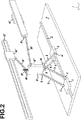
図1と2で図解的に示されるデバイスは、単純化されたデバイスであり、そこでは多数の構造の要素が削減されている。端部要素により移動可能な工作物は、例えば図3のデバイスにより実現可能なものほど大きくないが、その際別の寸法は同じに保持されるが、構造の単純化により得られる可動要素の重量の減少は、それらのための特定の用途、例えば精度が主な重要性である用途の可能性を開発する。 The device schematically shown in FIGS. 1 and 2 is a simplified device in which a number of structural elements have been reduced. The workpiece movable by the end element is not as large as that which can be achieved, for example, by the device of FIG. 3, but the other dimensions are kept the same, but the weight of the movable element obtained by the simplification of the structure This opens up the possibility of specific applications for them, such as applications where accuracy is of primary importance.
図1に示されるデバイスの平面ベース1の表面において、角柱のガイド2が形成されており、それは、直線であって、移動において1つの自由度を有していて、約束上「x軸」と呼ばれる、軸を規定する。2つのモーター駆動のスライド(滑動部)3と4は、ガイド2に設置されるので、スライドの動きは、それらをx軸に沿ってお互いから独立して駆動可能な状態で制御される。各その端部において、即ちxに対して実質的に垂直に保持される線において、各スライド3と4は、2つのボール及びソケットジョイント5,6を具備しており、前記ジョイント5,6は対の剛な支持バー7,8を受容するためのスライドにおける隣接点及びジョイントとして作用しており、対の支持バーの上端部は順に、プラットフォーム11を対のバー7と8により形成される2つの脚にヒンジ止めする、それぞれの対のボール及びソケットジョイント9,10を具備する。各対7又は8の2つのバーは平行であることが好ましい。プラットフォーム11は、この例において矩形のブロックにより図示されており、そのブロックの矩形の底面はその各角部において、ボール及びソケットジョイント9,10の1つを具備する。ボール及びソケットジョイント9又は10はまた、プラットフォーム11の矩形ブロック形状の体積内の任意の場所に設置されても良く、その場合には、各対における2つのボール及びソケットジョイント9,10は、プラットフォーム11の回転軸に平行な直線上に設置される状態である。プラットフォーム11は、端部要素(能動的又は受動的要素)21の本体に堅固に固定されており、前記端部要素は例えば、切削カッター又は何か別の回転式工具を支持するスピンドルであり、それの回転軸はプラットフォームに対して任意の方法で角度を持って位置決めされても良い。
On the surface of the
デバイスは、付属構造を更に具備しており、付属構造は、プラットフォーム、従って端部要素21の2つの残りの自由度を制御する。この構造は、第1にプラットフォームの旋回を駆動するように作用する旋回バー14を具備し、第2にy軸に沿ってプラットフォームの自由度を制御するように稼働する側部バー18を具備する。
The device further comprises an attachment structure, which controls the two remaining degrees of freedom of the platform and thus the
旋回バー14は、ボール及びソケットジョイント13を介してその端部の1つにおいて、脚7と8を駆動する前記スライド3及び4がその上を走行可能である場所の外側で、角柱ガイド2に沿って動くように構成されたモーター駆動スライド12にヒンジ止めされる。それ(旋回バー14)は、ボール及びソケットジョイント15を介してそれの別の端部において、プラットフォーム11に固定されていて且つそれに対して横に突き出る、要素20の端部にヒンジ止めされる。この形態は、作業空間全体を通して、端部要素に作用してスライド12の運動の下でそれを旋回させる力の方向と、ボール及びソケットジョイント10と15を通過する直線との間で垂直に非常に近い、角度を保持可能にする。この特性については、旋回駆動部(ドライブ)の「剛性のある角度的追跡移動(トラッキング)」として、説明の残部において説明されており、更にそれは、従来デバイス(装置)により達成されたものに比べて、より大きな角度的ストローク及びより高い剛性を有する、非常に高い性能レベルを実現することを可能にする。
The
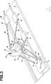
例として、120度の角運動にわたり一定のプラットフォーム11の角度的位置決めを保証するトルクを保持するために、図3に示される第2の実施の形態は、本発明のデバイスの「剛性ある角度的追跡移動」特性により、デバイスが合理的な寸法を有する場合に、軸線30に垂直であって且つ旋回板29に作用する、合成力の要素が、その最小値に対して単に15%で変動することを可能にする。
As an example, in order to hold the torque to ensure the angular positioning of the fixed platform 11 over the angular movement of 120 °, angular second embodiment shown in FIG. 3, there "rigid devices of the present invention Due to the “tracking movement” characteristic, the component of the resultant force acting on the
振幅の同じオーダー(程度)の結果は、本出願に記載される別の実施の形態により実現可能である。 Results of the same order (degree) of amplitude can be achieved with another embodiment described in this application.
ボール及びソケットジョイント13がスライド12の角部に設置されており、スライド12の角部自体がガイド2に対して対称である位置に配置されるにも係わらず、ボール及びソケットジョイントにより、開示される形態はデバイスのy軸に沿う自由度を制御しない(y軸に沿う自由度が残される)。この制御は、側部バー18により実現されており、側部バー18はその端部の1つにおいて、ボール及びソケットジョイント17を介して、角柱ガイド23に沿って動くように構成されたモーター駆動スライド16にヒンジ止めされており、その角柱ガイド23は矩形で、移動において1つの自由度を有しており、ガイド2に平行で更にベース1の表面に配設される。バー18はその別の端部において、ボール及びソケットジョイント19を介して要素20にヒンジ止めされる。ボール及びソケットジョイント19は必ずしも要素20に設置される必要はないが、しかしむしろそれはまたプラットフォーム11又は端部要素21に設置可能であることが規定されるべきである。
The ball and socket joint 13 is installed at the corner of the
この形態は、作業空間全体を通して、端部要素21の位置決めに関して完全な制御を行うのに十分である。
This configuration is sufficient to provide complete control over the positioning of the
スライドは、その駆動部材が固定されたラックに噛み合う、モーター、又はボールネジ、又はチェーン牽引システム(装置)、又はこれとは別にリニアモーター又は何か別の手段により駆動されるトラック(輸送車両)として設計されても良いことが分かる。各ボール及びソケットジョイント5,6,9,10,13,15,17及び19はバーを、それを支持する部分、又はそれが任意の軸周りで、その構造に依存する振幅で支持する部分にヒンジ止めする。ボール及びソケットジョイントはユニバーサルジョイントタイプであっても良い。
A slide is a motor (or ball screw) or chain pulling system (device) that engages a rack to which its drive member is fixed, or a track (transportation vehicle) that is driven by a linear motor or some other means. It turns out that it may be designed. Each ball and
図1のデバイスは、前もって決められた作業空間xyzの範囲内の任意の地点においてだけではなく、y軸に平行な旋回軸の周りでの端部要素21の軸の前もって決められた角度的位置決めに関しても、端部要素21の位置を正確に位置決めし更に制御するような状態で形成されても良いことが分かる。付属構造12から20が存在しない状態において、プラットフォーム11と端部要素21を具備するアセンブリは、脚7,8により支持されており、更にスライド3,4の各位置に関して、それに関する2つの自由度が残されており、その2つの自由度は、平行四辺形7,8を変形することによる平面yzにおける円孤(アーク)状の運動、及びy軸に平行であって且つ脚7の軸線及び脚8の軸によりそれぞれ形成された平面間の交差線に対応する、仮想の回転軸の周りの回転である。これらの2つの自由度は、角柱ガイド2,23に沿うスライド12と16の相対的位置により正確に制御される。角柱ガイドの位置及び旋回バー14と側部バー18との長さは、端部要素21が到達可能な作業空間を完全に決定する。
Device of Figure 1, not only at any point within the range of pre-determined work space xyz, advance-determined angular positioning before the axis of the
図1に示される例において、ガイド2と23は、平行なガイドであるが、しかし当然にそれらはまた空間の任意の方向に配設されても良く、あるいはそれらは曲線であっても良い。同様に、スライド3,4と12は個別のガイドに沿って動くことが出来る。更に、直線で囲まれた角柱ガイドは、1つの自由度を有していて且つ旋回可能に設置されたレバーにより置換可能であり、従って例えば、スライド3,4はyに平行な旋回軸を有する2つのレバーにより置換可能である。スライド12と16は、任意の方法で位置決めされた旋回軸を有するレバーにより置換されても良い。レバーは選択可能にモーター駆動であっても良い。上記の注記はまた、以下に記載の別の実施の形態及び変形形態の全てに適用される。
In the example shown in FIG. 1, guides 2 and 23 are parallel guides, but of course they may also be arranged in any direction in space, or they may be curved. Similarly, slides 3, 4 and 12 can move along separate guides. In addition, the straight-lined prismatic guide has one degree of freedom and can be replaced by a pivotally mounted lever, so that, for example, the
例として、図10は、図1に示される第1の実施の形態の第2の変形形態を示しており、そこではスライド2と4は、レバー3’と4’により置換され、スライド12と16はレバー12’と16’により置換されている。 By way of example, FIG. 10 shows a second variant of the first embodiment shown in FIG. 1, in which slides 2 and 4 are replaced by levers 3 ′ and 4 ′, 16 is replaced by levers 12 'and 16'.
図2は第1の実施の形態の付属構造の単純化された変形形態を示す。この変形形態において、旋回バー14’と側部バー18’とのモーター駆動スライド12’と16’は、それぞれの角柱ガイド22と23’に設置されており、それら(角柱ガイド22と23’)は、矩形で、1つの自由度を有しており、更にガイド2に平行であり、即ちx軸に沿って角度的に位置決めされているが、しかしベース1の平面に対してz軸に沿って幾らかの距離を持って設置されるように持ち上げられる。これらのガイド22と23’は、デバイスの左右対称の垂直平面xzのいずれかの側に設置される。ガイド22と23’の形態の図面において、要素20の存在は、申し分のない剛性のある角度的追跡移動(トラッキング)を実現するのに必要ではなく、ボール及びソケットジョイント15’と19’は、プラットフォーム11に、好適にはその頂面の端部の1つに、直接的に設置されても良い。この変形形態において、バー14’と18’は共に、旋回動を駆動すること及びy軸に沿う自由度の制御において具備されることが認識されるはずである。
FIG. 2 shows a simplified variant of the attachment structure of the first embodiment. In this variant, the motor-driven slides 12 'and 16' of the swiveling bar 14 'and the side bar 18' are installed on the respective prism guides 22 and 23 'and they (the prism guides 22 and 23'). Is rectangular and has one degree of freedom and is parallel to the
図3は、図1と同じ図式図により、本発明のデバイスの第2の実施の形態を示す。上記した要素の多くは、図3において認識可能であり、更にそれらは同じ参照符号により指定される。従って図3は、平行で且つx軸に沿って角度的に位置決めされる、2つの角柱ガイド2と23と、更に2つのスライド3と4とを示しており、スライド3と4は、第1の実施の形態において同じ参照符号により指定された要素と同じ部分を演じており、即ちボール及びソケットジョイント5と6により2対の支持バー7と8を支持し、各対の支持バーは、図1のように、端部要素21に固定されたプラットフォーム11に接続される、2つのボール及びソケットジョイント9又は10を支持する。プラットフォームを支持するための「脚」の形態は、第1の実施の形態と同じである一方で、端部要素21の2つの残りの自由度を制御する付属構造は、第1の実施の形態の付属構造とは異なる。
FIG. 3 shows a second embodiment of the device of the present invention by the same schematic diagram as FIG. Many of the elements described above are recognizable in FIG. 3, and they are designated by the same reference numerals. FIG. 3 therefore shows two
図1のように、付属構造は、スライド12と16に設置された側部バー18と旋回バー14を具備しており、それ(スライド12と16)は、図1を参照して説明された状態と同一の状態で、角柱ガイド2と角柱ガイド23に沿ってそれぞれ移動する。対照的に、プラットフォームの旋回を制御するために、図3のデバイスは、3つの剛な部材を有しており、所謂、旋回板29、駆動バー14及び制御バー27である。旋回板29は、y軸に平行な軸線30のピンを介してプラットフォーム11にヒンジ止めされる。それは、台形形状の要素の形で図示されており、その先端の角部は、バー14と18をヒンジ止めするための2つのボール及びソケットジョイント15と19と、制御バー27にヒンジ止めされる第3のボール及びソケットジョイント28とを支持する。制御バー27の別の端部は、ボール及びソケットジョイント26を介してスライド3の部分25に設置される。スライド3上のボール及びソケットジョイント26の位置は決定的ではない。ボール及びソケットジョイント26はまた、より以上に前方であるか又はより以上に後方で、更により高いか又はより低くても良い。同様に、ボール及びソケットジョイント28と15の中心は、旋回板29の体積内のどこに配置されても良いが、しかしそれらは軸線30上に設置されてはならない。
As shown in FIG. 1, the attachment structure comprises a side bar 18 and a
側部バー18は必ずしも旋回板に接続される必要はないが、しかしむしろそれは、y軸に沿う動きが実現されるように、駆動デバイスの任意の別の要素に接続されても良い。 The side bar 18 does not necessarily need to be connected to the swivel plate, but rather it may be connected to any other element of the drive device so that movement along the y-axis is achieved.
端部要素は、もしスライド3,4,12と16自身がそれらのそれぞれの角柱ガイドに固定される場合に固定されており、更に30に平行な軸線周りの回転又は作業空間における移動のいずれかにおける任意の動きは、該スライドを駆動するモーターに作用することにより制御されても良い。
The end elements are fixed if the
図4は、本発明のデバイスの第2の実施の形態の横の動きのないの変形形態を示す。前出の実施の形態のように、2つのスライドに設置された2つの脚を有する、同じ支持構造と、中間ジョイントを有する同じ付属旋回構造とが図示される。スライド16と側部バー18とが存在しないので、y軸の沿う動きは、デバイスと、端部要素が作用する対称物を保持するための手段との間の相対的動きにより、この例において実現される。用語「右手と左手」のデバイスがまた使用されても良い。
FIG. 4 shows a non-lateral movement variant of the second embodiment of the device of the invention. As in the previous embodiment, the same support structure with two legs installed on two slides and the same attached pivot structure with an intermediate joint are shown. Since there are no
この例において、ベース1は、単一の角柱ガイド2を支持しており、そこに全ての3つのスライド3,4と12が設置される。プラットフォームの任意の制御されない横の動きを回避するために、対の支持バー7又は8の1方の2つのバーは共に、堅固に接続されなければならないが、それは、少なくとも一つの脚において、少なくとも脚の1つにおいて、ボール及びソケットジョイントが、軸線30に平行な軸線を有するピボットにより置換される、単一の要素を有する対のバーを置換するものと同じである。2つのピボット(旋回)を有する別の形態もまた案出されても良い。
In this example, the
付属構造は、ジョイント9と10の周りで、端部要素21に固定されるプラットフォーム11を旋回しており、それは、ピン30と、旋回板29とを具備しており、それらの先端角部には、板29を制御バー27と旋回駆動バー14とに接続する中間ジョイント28と15が設置されており、それ(旋回駆動バー14)自体はスライド12のジョイント13に支持される。ジョイント9と10は、それらの軸線が一致するように、結合されても良い。同じことがジョイント28と15に適用される。
The attachment structure swivels around the
図4は、点線により角運動の範囲を示しており、その角度運動は、付属構造が2つの端部位置12aと12bの間でスライド12を単に動かすことにより、プラットフォーム11に伝達可能である。制御バー27の対応する位置は27aと27bで示される。
FIG. 4 shows the range of angular movement by dotted lines, which can be transmitted to the platform 11 simply by moving the
図5に示される第3の実施の形態は、第1に、スライド12が同じ方向に動かされる場合に、図3のデバイスのプラットフォームの動きに比較して、プラットフォームの反対の動きを生じる、旋回板29’の形態により、図3に示される実施の形態とは異なる。幾つかのケースにおいて、この形態は、特に有利な運転条件を実現可能である。
The third embodiment shown in FIG. 5 is a swivel that firstly produces an opposite movement of the platform when the
この例はまた、端部要素21がプラットフォーム11に堅固に固定されており、更に全てのジョイントが、(単純な)ジョイント30に関してを除いて、ボール及びソケットジョイントタイプにより形成されており、ジョイント30を介して旋回板29’は、ジョイントがy軸に沿って角度的に位置決めされるプラットフォームにヒンジ止めされる。
This example also shows that the
この例においても、ベース板1は2つの平行な角柱ガイド2と23を支持する。2つのスライド3と4は、図3のスライド3と4と正確に同じ方法で作動しており、それらは、角柱ガイド2に設置される。ボール及びソケットジョイント5,6を介してそれらは、2つの平行四辺形を形成していて且つプラットフォーム11を支持するための2つの支持脚を形成する、対の支持バー7,8を支持する。図3のように、旋回板29’上のボール及びソケットジョイントの位置は、それらが軸線30上に設置されない条件で、決定的ではない。2つの剛な部材及び中間ジョイントを有する付属構造はまた、この例において示されるはずである。しかし、アセンブリは、プラットフォーム11の旋回運動が、図3に示されるデバイスのプラットフォームの旋回する方向に反対の方向において生じるように構成される。このケースにおいて、スライド12は、ガイド2に設置されて、スライド3と4の間で動き、旋回板29’と旋回バー14との形態、及び側部バー18と制御バー27との形態は、旋回板が支持バー7の間で旋回可能なように選択される。
Also in this example, the
図5のデバイスの横の動きのない変形形態は図6に示される。このデバイスは実際には、図4に示されるデバイスの逆のものであると考えられることが出来、そこでは図4に示される3つの自由度を有するデバイスに対する相違は単に、旋回ジョイント9と10に比較したプラットフォーム上のジョイント30の位置にある。 A variant without lateral movement of the device of FIG. 5 is shown in FIG. This device can in fact be considered the inverse of the device shown in FIG. 4, where the difference to the device with three degrees of freedom shown in FIG. In the position of the joint 30 on the platform.
図3から6に示される全ての例において、ボール及びソケットジョイント15はまた、それがボール及びソケットジョイント26に一致しない条件で、バー27に固定可能であり、又はそれがボール及びソケットジョイント17に一致しない条件で、バー18に固定可能であり、あるいはボール及びソケットジョイント28は、それがボール及びソケットジョイント13に一致しない条件で、バー14に固定可能であり、又はそれがボール及びソケットジョイント26に一致しない条件で、バー27に固定可能である、ことが認識されるべきである。
In all examples shown in FIGS. 3 to 6, the ball and socket joint 15 can also be fixed to the
同様に、ボール及びソケットジョイント19は、それがボール及びソケットジョイント13に一致しない条件で、バー14に固定されても良く、又はそれがボール及びソケットジョイント26に一致しない条件で、バー27に固定されても良い。
Similarly, the ball and socket joint 19 may be fixed to the
結局、ボール及びソケットジョイント9は、それらがボール及びソケットジョイント6に一致しない条件で、バー8に固定されても良く、又はボール及びソケットジョイント10は、それらがボール及びソケットジョイント5に一致しない条件で、バー7に設置されても良い。
Eventually, the ball and
ところが上記の全ての例において、端部要素は、プラットフォームに堅固に固定されているのに反して、図7と8は、本発明のデバイスの第4の実施の形態の2つの例を示しており、そこでは端部要素21は堅固に拘束されないで、50で指定されるプラットフォームにより可動である。プラットフォームを支持し動かすための構造は、これらの2つの例において、特許EP0250470及び米国特許第4,976,582号に開示されるタイプの構造であり;即ち、プラットフォームの3つの基本的な自由度は、3つの平行な角柱ガイド43,44と45のそれぞれの1つに沿って動く3つのモーター駆動スライド40,41と42の基礎において平行に形成されており、更に各々は、プラットフォーム50を支持するそれぞれの脚46,47と48を駆動してベース1に対するプラットフォームの平行状態を保持するような構造である。説明された構造の3つの脚の各々は、ボール及びソケットジョイントを介して、それらを支持するスライドに対して且つプラットフォームの一方の側においてヒンジ止めされる対の支持バー46,47と48により形成される。構造は従って、3つの変形可能な平行四辺形を有しており、その平行四辺形は、ベースに平行なプラットフォームを保持し、更に形成される作業空間全体を通してプラットフォームを移動させるように駆動可能である。この例において端部要素21は、プラットフォームに関連する軸線51の周りで旋回するような状態で、プラットフォームにヒンジ止めされる。
However, in all the above examples, the end elements are firmly fixed to the platform, whereas FIGS. 7 and 8 show two examples of the fourth embodiment of the device of the invention. In which the
付属構造は、端部要素21を軸線51の周りで制御された状態で旋回可能にしており、それは、端部要素21のその端部の一方において旋回可能に搭載される旋回板29”を具備して、軸線30’の周りで旋回しており、更に旋回バー14”及び制御バー27”と協働する。旋回バー14”は、その一方の端部においてモーター駆動スライド12”にヒンジ止めされており、スライド12”は、角柱ガイド43に沿って可動であり、更にその別の端部において旋回板29”にヒンジ止めされる。制御バー27”は、その一方の端部26”においてスライド40にヒンジ止めされており、更に軸線30’に一致しない場所において、その別の端部において板29にヒンジ止めされる。変形形態において、ジョイント26”はまた、軸線51に一致しない場所において、プラットフォーム50に設置可能である。
The attachment structure makes the
図7と8に示される2つの変形形態は、旋回板29”のそれらの形態が、端部要素21の旋回運動を生じており、更にその旋回運動は、スライド12”が同じ方向で動かされる場合に、反対であることにおいて異なる。
In the two variants shown in FIGS. 7 and 8, those forms of the
説明された別の実施の形態のように、スライド40,41と42は、旋回可能に設置されたレバーにより置換可能であり、この例におけるレバーの旋回軸線が、脚46,47と48のベースに設置されるボール及びソケットジョイントの中心を通るそれぞれの軸線に平行であることが必要である。スライド12”は、任意の方法で位置決めされた軸線の周りで旋回するように設置されたレバーにより置換されても良い。
As in the alternative embodiment described, the
図7と8に示される例において、ボール及びソケットジョイント15”はまた、それがボール及びソケット26”に一致しない条件で、バー27”に固定可能であるか、あるいはボール及びソケットジョイント28”は、それがボール及びソケット13”に一致しない条件で、バー14”に固定可能であることが認識されるべきである。
In the example shown in FIGS. 7 and 8, the ball and socket joint 15 "can also be fixed to the
図9が説明のため残っている。図9は、機械工具における本発明のデバイスの使用例を示す。この用途を示すために選択された実施の形態は、図2のデバイスのスライド12と16に対応するスライド60と61が、x軸に平行な別個の角柱ガイドにおいて案内されることを除いて、図3に示される実施の形態と同様である。スライド48と49は、図3のデバイスのスライド3と4に対応する。
FIG. 9 remains for explanation. FIG. 9 shows an example of the use of the device of the invention in a machine tool. The embodiment chosen to illustrate this application is that slides 60 and 61 corresponding to
例えば、ベース1は、作業台89上で例えば45度で傾けられる板であり、その作業台89はその軸線が垂直である回転台90を具備する。回転台は、プラットフォーム91に固定された端部要素92の工具が種々の機械加工オペレーションを実施可能である、工作物を受容するように設計される。選択可能に駆動される工作物キャリア(運搬機)を備える端部要素92を装備すること、及び回転台を一以上のモーター駆動又は受動的工具、又は両タイプの工具の組み合わせで置換すること、及び工具を通過して工作物を動かすことにより機械加工を実施すること、を考えることも出来る。
For example, the
一般的に、第2のバーを各単一のバー、例えば14,18,27に追加することが可能であり、第2のバーは、単一のバーに対して平行であり、それに対して同一に作動する。これは、デバイスの安定性を改善し、更にその剛性を増大することを可能にする。結果の過度な(ハイパー)案内のマイナス効果は、例えば高度の精密さを実施すること又は平衡(バランス用)レバーを挿入すること等の、既知の解決方法により大きな範囲で除去可能である。 In general, it is possible to add a second bar to each single bar, eg 14, 18, 27, the second bar being parallel to the single bar, against which Works the same. This makes it possible to improve the stability of the device and further increase its rigidity. The negative effect of the resulting excessive (hyper) guidance can be eliminated to a large extent by known solutions, for example by implementing a high degree of precision or inserting a balancing lever.
Claims (11)
基準平面を形成する固定ベース(1)と、
所定の作業空間内で、前記端部要素(21)を駆動するように配置された支持及び駆動構造と、を具備する、運動デバイスにおいて、
前記支持及び駆動構造は、
前記作業空間のX軸を形成する唯1つの自由度で移動するために前記ベース(1)において案内される、少なくとも2つの案内部材(3,4;40,41,42)と、
一定の長さの少なくとも2つの剛な脚(7,8;46,47,48)と、
前記端部要素(21)を支持するプラットフォーム(11;50)と、
各前記案内部材(3,4)を前記脚(7,8)の1つの脚の一方の端部に接続し且つ前記脚のもう一方の端部を前記プラットフォーム(11)に接続する、支持・駆動ジョイント装置(5,9,6,10)と、
を具備しており、
前記支持及び駆動構造は、前記プラットフォーム(11)に属する、旋回軸の周りで前記端部要素(21)を旋回させるための付属構造を更に具備しており、それにより、前記旋回軸を、その前の位置に平行に、X軸に垂直なY方向で変位させており、
前記付属構造は、
唯1つの自由度で移動するように前記ベース(1)上で案内される、付属案内部材(12;16)と、
固定された長さの付属の剛な駆動要素(14)と、
前記駆動要素(14)の一方の端部を前記付属案内部材(12)に接続する、ジョイント(13)と、
前記駆動要素(14)のもう一方の端部と前記プラットフォーム(11)との間にある移行構造(20,15)であって、前記移行構造における移行ジョイント(15)を介して、前記付属案内部材(12)の変位に対応して前記端部要素(21)に力を伝達する、移行構造(20,15)と、
を具備しており、
前記移行構造(20,15)の配置及び前記プラットフォーム(11)に対する前記移行ジョイント(15)の位置は、前記移行ジョイント(15)における前記力の方向が、作業空間内の前記端部要素(21)の全ての位置に関して、前記移行ジョイント(15)を前記旋回軸に接続する線に実質的に垂直な位置に保持されるので、それにより、前記作業空間内において、前記端部要素(21)に作用する、トルクには、前記作業空間内の前記端部要素の位置に関係なく、実質的に一定である、ことを特徴とする運動デバイス。Supporting the instrument or machine end element (21) a movement device for且one drive movement,
A fixed base (1) forming a reference plane;
Within a predetermined work space, anda support and drive structure arranged so as to drive said end element (21), in motor device,
The support and drive structure is
At least two guide members (3, 4; 40, 41, 42) guided in the base (1) to move with only one degree of freedom forming the X axis of the working space;
At least two rigid legs of constant length (7, 8; 46, 47, 48);
A platform (11; 50) supporting the end element (21);
Each guide member (3, 4) is connected to one end of one leg of the leg (7, 8) and the other end of the leg is connected to the platform (11). Drive joint device (5, 9, 6, 10);
It has
The support and drive structure further comprises an attachment structure belonging to the platform (11) for pivoting the end element (21) about a pivot axis, whereby the pivot axis is Displaced in the Y direction perpendicular to the X axis, parallel to the previous position,
The attached structure is
An attached guide member (12; 16) guided on the base (1) so as to move with only one degree of freedom;
An attached rigid drive element (14) of fixed length;
A joint (13) connecting one end of the drive element (14) to the auxiliary guide member (12);
Transition structure (20, 15) between the other end of the drive element (14) and the platform (11), via the transition joint (15) in the transition structure, the auxiliary guide A transition structure (20, 15) for transmitting force to the end element (21) in response to displacement of the member (12);
It has
The arrangement of the transition structure (20, 15) and the position of the transition joint (15) relative to the platform (11) is such that the direction of the force at the transition joint (15) is such that the end element (21 in the work space). for all positions of), because it is held in a substantially vertical position to a line connecting the transition joint (15) to said pivot axis, whereby, in said working space, said end element (21 The movement device is characterized in that the torque acting on the device is substantially constant regardless of the position of the end element in the work space.
前記移行構造は、中間ジョイント(28)を介して前記旋回板(29)にその一方の端部でヒンジ止めされていて且つ前記支持及び駆動構造の前記案内部材の1つ(3)にそのもう一方の端部でヒンジ止めされる、制御バー(27)を更に具備しており、
それにより、前記付属の旋回バー(14)は、前記移行ジョイント(15)を介して前記旋回板(29)に接続して、前記移行ジョイント(15)を介して前記旋回板に合成力を伝達する一方で、前記制御バー(27)は前記合成力の方向を制御することを特徴とする請求項1に記載のデバイス。The transition structure (30, 29, 27) comprises a swivel plate (29) connected to the platform (11) via an axis (30) belonging to the platform (11) and parallel to the swivel axis. And
The transition structure is hinged at one end to the pivot plate (29) via an intermediate joint (28) and to one of the guide members (3) of the support and drive structure. Further comprising a control bar (27) hinged at one end;
Thereby, the attached swivel bar (14) is connected to the swivel plate (29) via the transition joint (15) and transmits the resultant force to the swivel plate via the transition joint (15). Meanwhile, the device according to claim 1, wherein the control bar (27) controls the direction of the resultant force.
前記スライドは、前記ベース(1)と一体の案内手段(2,23)上で移動し、前記作業空間の前記X軸を形成する、同じ方向を有しており、
前記少なくとも2つの脚は、一定の長さで2対の平行な剛なバー(7,7,8,8)を具備しており、各対の剛なバーは、前記支持スライド(3,4)の1つを前記プラットフォーム(11)に接続し、別の側部バー(18)は、前記側部スライド(16)と前記移行構造(20,15)との間で伸張しており、
前記支持及び駆動ジョイント配置は、8つのジョイント(5,6,9,10)を具備しており、その内の4つのジョイントは、対の平行な支持バー(7,7,8,8)を前記支持スライド(3,4)に接続し、他の4つのジョイントは、前記対の支持バー(7,7,8,8)を前記プラットフォーム(11)に接続して、前記作業空間の前記Y方向に平行な2つの線を規定する、前記プラットフォーム上の位置を有しており、
前記旋回軸は、前記支持バー(7,7,8,8)の軸をそれぞれ含むように決定される、2つの平面の交差線である、ことを特徴とする請求項1に記載のデバイス。In the support and drive structure (3,4,7,8,11,20,12,14,16,18), the at least two guide members include two support slides (3, 4) and another side. Part slide (16),
The slide has the same direction as moving on the guide means (2, 23) integral with the base (1) and forming the X axis of the working space;
The at least two legs comprise two pairs of parallel rigid bars (7, 7, 8, 8) of a fixed length, each pair of rigid bars being connected to the support slide (3,4). ) Is connected to the platform (11), and another side bar (18) extends between the side slide (16) and the transition structure (20, 15),
The support and drive joint arrangement comprises 8 joints (5, 6, 9, 10), of which 4 joints have a pair of parallel support bars (7, 7, 8, 8). Connected to the support slide (3, 4), the other four joints connect the pair of support bars (7, 7, 8, 8) to the platform (11), and the Y of the work space Having a position on the platform defining two lines parallel to the direction;
2. Device according to claim 1, characterized in that the pivot axis is an intersecting line of two planes determined to include the axes of the support bars (7, 7, 8, 8), respectively.
一定の長さの3つの剛な脚(46,47,48)は各々、前記案内部材の1つと前記プラットフォーム(50)との間で伸張しており、
前記プラットフォーム(50)は、それが移動においてのみ強制して動かされるような状態で、前記支持及び駆動構造を介して前記ベースに設置されており、
前記移行構造は、付属旋回軸(51)を具備しており、前記旋回軸(51)を介して、前記端部要素(21)は、前記プラットフォーム(50)にヒンジ止めされており、前記付属旋回軸は前記Y方向を有する、ことを特徴とする請求項1に記載のデバイス。The support and drive structure (40, 41, 42, 46, 47, 48) is guided in the base (1) to move with only one degree of freedom forming the X axis of the working space. 3 guide members (40, 41, 42)
Three rigid legs (46, 47, 48) of fixed length each extend between one of the guide members and the platform (50);
The platform (50) is installed on the base via the support and drive structure in such a way that it is forced to move only in movement;
The transition structure comprises an attached pivot axis (51), through which the end element (21) is hinged to the platform (50), the attached axis The device of claim 1, wherein a pivot axis has the Y direction.
前記付属構造において、前記移行構造は、前記プラットフォーム(11)に一体で且つそこから後方に突き出る、剛な部分(20)を具備しており、
前記移行ジョイント(15)は、前記剛な旋回バー(14)を介して前記複合部材に作用する前記力の作用点を決定する、位置において、前記突き出た部分(20)に設置されており、
前記作用点に前記力が作用することにより、前記端部要素には、実質的に一定であるトルクが作用する、ことを特徴とする請求項1に記載のデバイス。The end element (21) and the platform (11) form a single composite member;
In the attachment structure, the transition structure comprises a rigid portion (20) that is integral with and projects rearwardly from the platform (11);
The transition joint (15) is located at the protruding portion (20) at a position that determines the point of action of the force acting on the composite member via the rigid swivel bar (14);
The device according to claim 1 , wherein a torque that is substantially constant acts on the end element when the force acts on the point of application .
前記移行構造は、前記剛な旋回バー(14)と前記プラットフォーム(11)との間に設けられたジョイント(15)により形成されており、
ガイド(2)が、ベース(1)上に設けられて、前記付属構造は、前記ガイド(2)に沿って動くように案内される、ことを特徴とする請求項1に記載のデバイス。The end element (21) and the platform (11) form a single composite member consisting of two parts fixed to each other;
Before Symbol transition structure is made form a joint (15) provided between said rigid swivel bar (14) and said platform (11),
2. Device according to claim 1, characterized in that a guide (2) is provided on the base (1) and the attachment structure is guided to move along the guide (2) .
前記案内手段は、前記作業空間の前記X軸を形成する、同じ方向で伸張するように配置される、デバイスにおいて、
前記支持及び駆動構造は、
前記X軸に平行に、前記ベース上で移動する、付属側部案内部材(16)と、
側部バージョイント(17)を介して前記側部案内部材(16)に接続する、一方の端部と、側部ジョイント(19)を介して前記プラットフォーム(11)に直接的又は間接的に接続する、他方の端部とを有する、側部バー(18)と、
を更に具備しており、
それにより、前記側部案内部材(16)の変位は、前記旋回軸及び前記Y軸に平行な方向で、前記プラットフォーム(11)を変位させる、ことを特徴とする請求項1に記載のデバイス。Said support and drive structure comprises a fixed base with means (2) for guiding two guide members (3, 4), each guide member (3, 4) being a joint ( 5, 6) to one end of one of the two legs (7, 8), said leg (7, 8) being connected to said end by its other end Connected to the platform (11) supporting the element,
In the device, the guide means is arranged to extend in the same direction forming the X axis of the working space;
The support and drive structure is
An attached side guide member (16) that moves on the base parallel to the X axis;
One end connected to the side guide member (16) via a side bar joint (17) and directly or indirectly connected to the platform (11) via a side joint (19) A side bar (18) having the other end;
Further comprising
2. The device according to claim 1, wherein the displacement of the side guide member (16) displaces the platform (11) in a direction parallel to the pivot axis and the Y axis.
Applications Claiming Priority (2)
| Application Number | Priority Date | Filing Date | Title |
|---|---|---|---|
| EP01810193A EP1234632A1 (en) | 2001-02-23 | 2001-02-23 | Kinematic device for programmably supporting and positioning an end element in a machine or an instrument |
| PCT/CH2002/000100 WO2002066203A1 (en) | 2001-02-23 | 2002-02-21 | Kinematic device for support and programmable displacement of a terminal element in a machine or an instrument |
Publications (3)
| Publication Number | Publication Date |
|---|---|
| JP2004524982A JP2004524982A (en) | 2004-08-19 |
| JP2004524982A5 JP2004524982A5 (en) | 2005-12-22 |
| JP4523228B2 true JP4523228B2 (en) | 2010-08-11 |
Family
ID=8183756
Family Applications (1)
| Application Number | Title | Priority Date | Filing Date |
|---|---|---|---|
| JP2002565749A Expired - Fee Related JP4523228B2 (en) | 2001-02-23 | 2002-02-21 | Motion device for supporting and programmably driving an end element in a machine or instrument |
Country Status (14)
| Country | Link |
|---|---|
| US (1) | US8303238B2 (en) |
| EP (2) | EP1234632A1 (en) |
| JP (1) | JP4523228B2 (en) |
| KR (1) | KR100882624B1 (en) |
| CN (1) | CN100462197C (en) |
| CA (1) | CA2439881C (en) |
| CZ (1) | CZ20032512A3 (en) |
| EA (1) | EA005147B1 (en) |
| HK (1) | HK1064636A1 (en) |
| HU (1) | HUP0303205A2 (en) |
| IL (2) | IL157476A0 (en) |
| PL (1) | PL205720B1 (en) |
| SK (1) | SK11642003A3 (en) |
| WO (1) | WO2002066203A1 (en) |
Families Citing this family (69)
| Publication number | Priority date | Publication date | Assignee | Title |
|---|---|---|---|---|
| DE10130738B4 (en) * | 2001-06-19 | 2010-12-30 | Tbt Tiefbohrtechnik Gmbh + Co | Device for adjusting a spindle |
| KR101101495B1 (en) | 2003-12-05 | 2012-01-03 | 자노메 미싱 고교가부시키가이샤 | A Robot |
| CN100548590C (en) * | 2004-06-10 | 2009-10-14 | Abb公司 | Parallel kinematic robot and control the method for this robot |
| DE102004030659B8 (en) * | 2004-06-24 | 2007-01-18 | Ruprecht Altenburger | mover |
| CN101232978A (en) * | 2005-07-29 | 2008-07-30 | 弗伦茨·埃伦莱特纳 | Stamp identification device |
| DE102005041496A1 (en) * | 2005-09-01 | 2007-03-08 | Index-Werke Gmbh & Co. Kg Hahn & Tessky | machine tool |
| CN100411826C (en) * | 2005-11-11 | 2008-08-20 | 华南理工大学 | Four-freedom parallel robot mechanism with two translational dimensions and two rotational dimensions |
| CN100427276C (en) * | 2005-11-11 | 2008-10-22 | 华南理工大学 | Five-freedom parallel robot mechanism with three translational dimensions and two rotational dimensions |
| CN100409992C (en) * | 2005-11-30 | 2008-08-13 | 江苏大学 | Laser material processing machine tool |
| CN100384599C (en) * | 2006-06-09 | 2008-04-30 | 燕山大学 | Four-freedom parallel mechanical arm |
| JP5159781B2 (en) * | 2006-09-21 | 2013-03-13 | エアバス オペラシオン(エス.ア.エス) | Machining means for ceiling fixing parts |
| DE102007010580B4 (en) * | 2007-03-05 | 2017-07-13 | Fraunhofer-Gesellschaft zur Förderung der angewandten Forschung e.V. | Device for moving a working platform of a processing machine and method for controlling a movement path of this working platform |
| CN101444914A (en) * | 2008-11-19 | 2009-06-03 | 浙江工业大学 | Three-DOF personified parallel manipulator |
| AT508495B1 (en) | 2009-07-09 | 2013-04-15 | Ehrenleitner Franz | MACHINE TOOL |
| US8973768B1 (en) * | 2009-10-09 | 2015-03-10 | Par Systems, Inc. | Gantry robot system |
| AT508150B1 (en) | 2009-10-09 | 2010-11-15 | Ehrenleitner Franz | PARALLEL KINEMATIC SWIVELING DEVICE |
| WO2011063511A1 (en) * | 2009-11-27 | 2011-06-03 | Mcmaster University | Automated in-bore mr guided robotic diagnostic and therapeutic system |
| CN102381557B (en) * | 2010-08-30 | 2013-08-28 | 鸿富锦精密工业(深圳)有限公司 | Device for separating and merging articles |
| CN101966652B (en) * | 2010-09-14 | 2011-10-26 | 常州大学 | Three-axis digital plane type parallel manipulator |
| CN102218596A (en) * | 2011-06-24 | 2011-10-19 | 江苏大学 | Serial-parallel laser process machine |
| CN102303186B (en) * | 2011-08-16 | 2013-09-04 | 江苏扬力数控机床有限公司 | Imperfect degree-of-freedom parallel connection five-axis computerized numerical control laser cutting machine |
| CN102303187B (en) * | 2011-08-16 | 2013-09-25 | 江苏扬力数控机床有限公司 | Three-dimensional five-axis computerized numerical control laser cutting machine |
| DE102011053800A1 (en) | 2011-09-20 | 2013-03-21 | Invite GmbH | Holding frame for a multi-coupling for filling and / or emptying a chemical plant container |
| PL396589A1 (en) * | 2011-10-10 | 2013-04-15 | Janusz Marcin Ejma | Machine with a tool manipulator, especially precision tool manipulator |
| CN102615645A (en) * | 2012-04-12 | 2012-08-01 | 重庆大学 | Six-degree-of-freedom high-maneuvering high-accuracy practical parallel connection robot |
| DE102013102034B4 (en) * | 2012-10-19 | 2014-10-30 | Josef Glöckl | Return device for automatic adjustment of the restoring force |
| EP2981398A4 (en) * | 2013-04-04 | 2016-11-16 | Ben Shelef | Improved kinematic mount |
| DE102013206125A1 (en) * | 2013-04-08 | 2014-10-09 | Krones Aktiengesellschaft | Device and method for handling articles |
| JP5723426B2 (en) * | 2013-09-02 | 2015-05-27 | 株式会社カイジョー | Drive mechanism and manufacturing apparatus |
| CN103754454B (en) * | 2014-01-20 | 2016-04-06 | 中广核检测技术有限公司 | A kind of movable supporting leg transfer of support frame |
| CN103895006B (en) * | 2014-04-14 | 2015-12-30 | 南京理工大学 | Planar three-freedom-degree parallel mechanism |
| CN104044135A (en) * | 2014-07-10 | 2014-09-17 | 北华航天工业学院 | Planar two-degree-of-freedom parallel robot mechanism |
| JP6053991B2 (en) * | 2015-01-14 | 2016-12-27 | 三菱電機株式会社 | Positioning device |
| JP5963968B1 (en) * | 2015-01-21 | 2016-08-03 | 三菱電機株式会社 | Positioning device |
| GB201505800D0 (en) * | 2015-04-02 | 2015-05-20 | Mclaren Applied Technologies Ltd | Motion arrangement |
| PL237444B1 (en) * | 2015-07-13 | 2021-04-19 | Akademia Gorniczo Hutnicza Im Stanislawa Staszica W Krakowie | Hybrid robot |
| US11548142B2 (en) * | 2015-11-25 | 2023-01-10 | Mitsubishi Electric Corporation | Parallel link device |
| CN105666468B (en) * | 2016-03-23 | 2018-05-18 | 中北大学 | A kind of big swing angle planer-type five-axle linkage series-parallel machine tool |
| US11614796B1 (en) * | 2016-04-19 | 2023-03-28 | Etherial Matter, Inc. | Virtual reality haptic system and apparatus |
| EP3342547B1 (en) * | 2017-01-02 | 2021-08-25 | Manz AG | Positioning unit |
| DE102017114148A1 (en) * | 2017-06-26 | 2018-12-27 | Eb-Invent Gmbh | Device for pivoting an object about a virtual axis |
| KR101981426B1 (en) * | 2017-07-10 | 2019-05-22 | 한양대학교 에리카산학협력단 | Artificial joint |
| RU2667236C1 (en) * | 2017-10-11 | 2018-09-17 | Федеральное государственное бюджетное образовательное учреждение высшего образования "Сибирский государственный индустриальный университет" | Spatial mechanism with circular lever base |
| FR3078660B1 (en) * | 2018-03-08 | 2020-10-02 | Renault Sas | AUTOMATED CHARGING DEVICE OF AN ELECTRIC VEHICLE |
| CN108890645B (en) * | 2018-06-30 | 2021-09-17 | 天津大学 | Compensation method for zero point error of driving joint of five-degree-of-freedom series-parallel robot |
| CN109052257B (en) * | 2018-09-21 | 2020-07-07 | 南京理工大学 | Lifting mechanism with three-dimensional spatial layout |
| CN109129427B (en) * | 2018-09-30 | 2023-06-20 | 华南理工大学 | Plane parallel mechanism device driven by double five-rod mechanism and control method |
| US11059166B2 (en) | 2018-11-14 | 2021-07-13 | Battelle Energy Alliance, Llc | Linear delta systems with additional degrees of freedom and related methods |
| US10906172B2 (en) * | 2018-11-14 | 2021-02-02 | Battelle Energy Alliance, Llc | Linear delta systems, hexapod systems, and related methods |
| US10821599B2 (en) | 2018-11-14 | 2020-11-03 | Battelle Energy Alliance, Llc | Dual linear delta assemblies, linear delta systems, and related methods |
| FR3088566B3 (en) * | 2018-11-16 | 2020-11-13 | Michelin & Cie | STRIP CUTTING SYSTEM BY HELICOIDAL KNIVES AND CORRESPONDING CUTTING PROCESS |
| CN111012499B (en) * | 2018-12-29 | 2021-07-30 | 华科精准(北京)医疗科技有限公司 | Medical auxiliary robot |
| CN110946653B (en) * | 2018-12-29 | 2021-05-25 | 华科精准(北京)医疗科技有限公司 | Operation navigation system |
| CN114269520B (en) | 2019-08-19 | 2024-02-06 | 康格尼博提克斯股份公司 | Parallel sports equipment with multifunctional tool orientation |
| CN110421545A (en) * | 2019-08-20 | 2019-11-08 | 四川建筑职业技术学院 | A kind of parallel mechanical arm grabbing device of pyramidal structure |
| CN110450141B (en) * | 2019-08-30 | 2022-06-10 | 燕山大学 | Four-branch-chain six-degree-of-freedom hybrid mechanism |
| EP3822043B1 (en) * | 2019-11-12 | 2023-11-01 | Prodrive Technologies Innovation Services B.V. | Manipulator for handsfree charging electric vehicles |
| CN110815187B (en) * | 2019-11-19 | 2022-06-24 | 同济大学 | Three-freedom-degree parallel mechanism without accompanying movement |
| CN111243374B (en) * | 2020-01-17 | 2021-12-17 | 杜建男 | Motion simulator with large translation stroke and high response speed |
| WO2021179209A1 (en) * | 2020-03-11 | 2021-09-16 | 苏州迈澜医疗科技有限公司 | Multi-degree-of-freedom parallel mechanism and parallel mechanism assembly |
| WO2021179210A1 (en) * | 2020-03-11 | 2021-09-16 | 苏州迈澜医疗科技有限公司 | Multi-degree-of-freedom parallel mechanism and parallel mechanism assembly |
| CN111515926B (en) * | 2020-04-07 | 2021-10-26 | 上海工程技术大学 | Parallel robot |
| DE102020120280A1 (en) | 2020-07-31 | 2022-02-03 | Krones Aktiengesellschaft | Device for gripping and transporting objects |
| CN112318549B (en) * | 2020-10-21 | 2022-05-13 | 天津大学 | Two-degree-of-freedom high-rigidity robot |
| CN112935897B (en) * | 2021-02-01 | 2022-08-09 | 北华航天工业学院 | Main feeding mechanism of parallel machine tool |
| CN116135479A (en) * | 2021-11-17 | 2023-05-19 | 通用汽车环球科技运作有限责任公司 | Six-degree-of-freedom and three-degree-of-freedom robotic system for automated and/or coordinated fastening operations |
| CN114346734B (en) * | 2022-01-04 | 2023-03-31 | 江苏凯乐金属科技有限公司 | Cutting device for metal material processing |
| CN117506870A (en) * | 2023-12-11 | 2024-02-06 | 河北农业大学 | Orchard operation device with serial-parallel mechanism |
| CN118080994A (en) * | 2024-04-23 | 2024-05-28 | 顺达模具科技有限公司 | Automobile gearbox gear machining and forming device |
Family Cites Families (14)
| Publication number | Priority date | Publication date | Assignee | Title |
|---|---|---|---|---|
| CH672089A5 (en) * | 1985-12-16 | 1989-10-31 | Sogeva Sa | |
| US5378282A (en) * | 1993-06-28 | 1995-01-03 | Pollard; Willard L. | Robotic tool manipulating apparatus |
| JP3640087B2 (en) * | 1994-11-29 | 2005-04-20 | 豊田工機株式会社 | Machine Tools |
| DE19525482A1 (en) * | 1995-07-13 | 1997-01-16 | Bernold Richerzhagen | Robot arm for sliding and positioning object in plane - has carriages moved by electric motor over guide rail whereby carriages are connected together by joint elements with workpiece fixed at mid point of joints |
| EP0868255B1 (en) * | 1995-12-20 | 1999-09-08 | Alexander Konrad Wiegand | Device for spatially moving a body with three to six degrees of freedom in a controlled manner |
| SE511804C2 (en) * | 1996-03-14 | 1999-11-29 | Abb Ab | Apparatus for relative movement of two elements |
| DE19611130A1 (en) * | 1996-03-21 | 1997-09-25 | Vdw Verein Deutscher Werkzeugm | Machine tool or toolholder platform orientation system |
| DE19654041A1 (en) * | 1996-12-23 | 1998-06-25 | Focke & Co | Device for handling objects |
| DE19710171C2 (en) * | 1997-03-12 | 2002-02-07 | Juergen Hesselbach | Manipulator with a parallel structure |
| WO1999008832A1 (en) * | 1997-08-20 | 1999-02-25 | Mikron Sa Agno | Device for moving and positioning an object in a plane |
| US5901936A (en) * | 1997-08-25 | 1999-05-11 | Sandia Corporation | Six-degree-of-freedom multi-axes positioning apparatus |
| WO1999032256A1 (en) * | 1997-12-22 | 1999-07-01 | Liechti Engineering Ag | Machine tool for machining elongated workpieces |
| DE19839366A1 (en) * | 1998-08-28 | 2000-03-02 | Guenter Pritschow | Multi-purpose mechanical linkage with translatory drive unit for industrial robot facilitates use of the same type of drive in a wide variety of arrangements |
| US6497548B1 (en) * | 1999-08-05 | 2002-12-24 | Shambhu Nath Roy | Parallel kinematics mechanism with a concentric sperical joint |
-
2001
- 2001-02-23 EP EP01810193A patent/EP1234632A1/en not_active Withdrawn
-
2002
- 2002-02-21 IL IL15747602A patent/IL157476A0/en unknown
- 2002-02-21 SK SK1164-2003A patent/SK11642003A3/en unknown
- 2002-02-21 WO PCT/CH2002/000100 patent/WO2002066203A1/en active Search and Examination
- 2002-02-21 EA EA200300921A patent/EA005147B1/en not_active IP Right Cessation
- 2002-02-21 CN CNB028068300A patent/CN100462197C/en not_active Expired - Fee Related
- 2002-02-21 CA CA2439881A patent/CA2439881C/en not_active Expired - Fee Related
- 2002-02-21 EP EP02710747A patent/EP1365887A1/en not_active Withdrawn
- 2002-02-21 KR KR1020037011109A patent/KR100882624B1/en not_active IP Right Cessation
- 2002-02-21 CZ CZ20032512A patent/CZ20032512A3/en unknown
- 2002-02-21 HU HU0303205A patent/HUP0303205A2/en unknown
- 2002-02-21 PL PL364104A patent/PL205720B1/en unknown
- 2002-02-21 JP JP2002565749A patent/JP4523228B2/en not_active Expired - Fee Related
-
2003
- 2003-08-19 IL IL157476A patent/IL157476A/en not_active IP Right Cessation
- 2003-08-22 US US10/648,730 patent/US8303238B2/en not_active Expired - Fee Related
-
2004
- 2004-10-07 HK HK04107684A patent/HK1064636A1/en not_active IP Right Cessation
Also Published As
| Publication number | Publication date |
|---|---|
| EP1234632A1 (en) | 2002-08-28 |
| IL157476A0 (en) | 2004-03-28 |
| CA2439881A1 (en) | 2002-08-29 |
| EA200300921A1 (en) | 2004-02-26 |
| EP1365887A1 (en) | 2003-12-03 |
| KR20030096262A (en) | 2003-12-24 |
| CA2439881C (en) | 2011-01-04 |
| PL364104A1 (en) | 2004-12-13 |
| PL205720B1 (en) | 2010-05-31 |
| WO2002066203A1 (en) | 2002-08-29 |
| SK11642003A3 (en) | 2004-05-04 |
| EA005147B1 (en) | 2004-12-30 |
| CN100462197C (en) | 2009-02-18 |
| US8303238B2 (en) | 2012-11-06 |
| IL157476A (en) | 2009-07-20 |
| HUP0303205A2 (en) | 2003-12-29 |
| CZ20032512A3 (en) | 2004-12-15 |
| HK1064636A1 (en) | 2005-02-04 |
| US20040052628A1 (en) | 2004-03-18 |
| CN1498149A (en) | 2004-05-19 |
| JP2004524982A (en) | 2004-08-19 |
| KR100882624B1 (en) | 2009-02-06 |
Similar Documents
| Publication | Publication Date | Title |
|---|---|---|
| JP4523228B2 (en) | Motion device for supporting and programmably driving an end element in a machine or instrument | |
| JP5890588B2 (en) | Device for sharpening a tool with a cutting edge such as a drill or a cutting tool | |
| US10603752B2 (en) | Machine tool | |
| CN107363838B (en) | Machine tool | |
| JP5372150B2 (en) | Machine tool with carrier device for workpiece or tool | |
| US20160193704A1 (en) | Machine tool for machining | |
| KR101848994B1 (en) | A translation type of delta robot and a surgical robot comprising thereof | |
| JP5370120B2 (en) | Work transfer device | |
| JPH11104987A (en) | Parallel link mechanism | |
| JP4494838B2 (en) | Processing system and processing method | |
| JP5891087B2 (en) | Tool position measuring apparatus and machining apparatus provided with the same | |
| CN110480762B (en) | Modular three-degree-of-freedom machining robot | |
| EP0997238B1 (en) | Parallel link mechanism | |
| JP4211190B2 (en) | Processing equipment using robots | |
| JPS60201845A (en) | Tool support device | |
| JP2004314189A (en) | Positioning device using parallel mechanism | |
| JP2009142971A (en) | Machine tool equipped with turnable moving portion | |
| JP6242205B2 (en) | Machine Tools | |
| JP2004529000A (en) | Parallel positioning mechanism, especially parallel positioning mechanism for machining and / or manipulation and / or measurement | |
| JP6242204B2 (en) | Machine Tools | |
| WO2024060103A1 (en) | Numerical control machine tool | |
| JP2010029960A (en) | Hybrid mechanism and machine tool with the same | |
| JP2022021726A (en) | Positioning unit and positioning table | |
| JP2003089024A (en) | Body structure for cantilever rectangular coordinate type machine | |
| JP2021000709A (en) | Robot and fingertip member for robot |
Legal Events
| Date | Code | Title | Description |
|---|---|---|---|
| A521 | Request for written amendment filed |
Free format text: JAPANESE INTERMEDIATE CODE: A523 Effective date: 20050214 |
|
| A621 | Written request for application examination |
Free format text: JAPANESE INTERMEDIATE CODE: A621 Effective date: 20050214 |
|
| A131 | Notification of reasons for refusal |
Free format text: JAPANESE INTERMEDIATE CODE: A131 Effective date: 20080603 |
|
| A601 | Written request for extension of time |
Free format text: JAPANESE INTERMEDIATE CODE: A601 Effective date: 20080902 |
|
| A602 | Written permission of extension of time |
Free format text: JAPANESE INTERMEDIATE CODE: A602 Effective date: 20080909 |
|
| A521 | Request for written amendment filed |
Free format text: JAPANESE INTERMEDIATE CODE: A523 Effective date: 20081203 |
|
| A131 | Notification of reasons for refusal |
Free format text: JAPANESE INTERMEDIATE CODE: A131 Effective date: 20091006 |
|
| A601 | Written request for extension of time |
Free format text: JAPANESE INTERMEDIATE CODE: A601 Effective date: 20100105 |
|
| A602 | Written permission of extension of time |
Free format text: JAPANESE INTERMEDIATE CODE: A602 Effective date: 20100113 |
|
| A521 | Request for written amendment filed |
Free format text: JAPANESE INTERMEDIATE CODE: A523 Effective date: 20100405 |
|
| TRDD | Decision of grant or rejection written | ||
| A01 | Written decision to grant a patent or to grant a registration (utility model) |
Free format text: JAPANESE INTERMEDIATE CODE: A01 Effective date: 20100427 |
|
| A01 | Written decision to grant a patent or to grant a registration (utility model) |
Free format text: JAPANESE INTERMEDIATE CODE: A01 |
|
| A61 | First payment of annual fees (during grant procedure) |
Free format text: JAPANESE INTERMEDIATE CODE: A61 Effective date: 20100527 |
|
| R150 | Certificate of patent or registration of utility model |
Free format text: JAPANESE INTERMEDIATE CODE: R150 |
|
| FPAY | Renewal fee payment (event date is renewal date of database) |
Free format text: PAYMENT UNTIL: 20130604 Year of fee payment: 3 |
|
| LAPS | Cancellation because of no payment of annual fees |