JP4518556B2 - Exhaust water cleaning equipment - Google Patents
Exhaust water cleaning equipment Download PDFInfo
- Publication number
- JP4518556B2 JP4518556B2 JP2004366642A JP2004366642A JP4518556B2 JP 4518556 B2 JP4518556 B2 JP 4518556B2 JP 2004366642 A JP2004366642 A JP 2004366642A JP 2004366642 A JP2004366642 A JP 2004366642A JP 4518556 B2 JP4518556 B2 JP 4518556B2
- Authority
- JP
- Japan
- Prior art keywords
- nozzle
- water
- exhaust gas
- gas introduction
- pipe
- Prior art date
- Legal status (The legal status is an assumption and is not a legal conclusion. Google has not performed a legal analysis and makes no representation as to the accuracy of the status listed.)
- Expired - Fee Related
Links
Images
Description
本発明は,半導体製造プロセス等から排出される排ガスを,当該排ガスに含まれる粉塵等の粉末状の固形物及び一部のガスを除去するために,水で洗浄するための装置に関するものである。 The present invention relates to an apparatus for washing exhaust gas discharged from a semiconductor manufacturing process or the like with water in order to remove powdery solids such as dust and some gas contained in the exhaust gas. .
従来,この種の排ガスに対する水洗浄装置は,例えば,特許文献1等に記載されているように,排ガスを,縦型容器内に,その頂部から導入して,下部から排出するようにする一方,前記縦型容器の内壁面に,水膜を,上から下向きに流れるように形成し,この水膜に,前記排ガスを直接接触し,次いで,この排ガスにスプレーノズルから水を噴霧することによって,水洗浄するという構成にしている。
しかし,この従来の水洗浄装置において,前記縦型容器内への排ガス導入管路の内径が,前記縦型容器の内径とを略同様に可成り大きいことにより,この排ガス導入管路における内壁面が,縦型容器内と同様に水分を多く含む雰囲気になっているから,排ガスが,塵埃等の粉末状固形物を含んでいる場合とか,或いは,水との接触によって粉末状固形物が析出する物質を含んでいる場合において,前記排ガス導入管路における内壁面に,前記粉末状固形物が付着・堆積して,当該排ガス導入管等を詰めることになる。 However, in this conventional water cleaning apparatus, the inner diameter of the exhaust gas introduction pipe line into the vertical container is substantially the same as the inner diameter of the vertical container. However, since the atmosphere contains a lot of moisture as in the vertical container, the powdered solids may be precipitated when the exhaust gas contains powdered solids such as dust or by contact with water. In the case where a substance to be discharged is included, the powdered solid matter adheres and accumulates on the inner wall surface of the exhaust gas introduction pipe, and the exhaust gas introduction pipe and the like are packed.
従って,従来の水洗浄装置においては,前記のように付着・堆積した粉末状固形物を除去するための清掃作業を,短い時間間隔で頻繁に行わなければならないから,これに多大の手数を必要するとするばかりか,稼働率が低いという問題があった。 Therefore, in the conventional water cleaning apparatus, the cleaning work for removing the powdered solid matter adhered and deposited as described above must be frequently performed at short time intervals, which requires a lot of work. Not only that, there was a problem that the utilization rate was low.
本発明は,この問題を解消した水洗浄装置を提供することを技術的課題とするものである。 This invention makes it a technical subject to provide the water washing apparatus which eliminated this problem.
この技術的課題を達成するため本発明の請求項1は,
「縦型容器内における上部に排ガス導入管路から導入した排ガスを,当該縦型容器内において水との直接接触にて洗浄したのち,その下部のガス出口から排出する水洗浄装置において,
前記排ガス導入管路は,下端にノズル部を備えた複数本の小径のガス導入ノズル管にて構成され,この各ガス導入ノズル管の下端におけるノズル部は,前記縦型容器内に,下向きに突出しており,更に,前記ガス導入ノズル管には,当該ガス導入ノズル管の内部を通って,その下端における前記ノズル部内に水又は空気を噴出するようにした詰まり清掃用ノズルが設けられている。」
ことを特徴としている。
In order to achieve this technical problem,
“In the water cleaning device, the exhaust gas introduced from the exhaust gas introduction pipe into the upper part in the vertical container is cleaned by direct contact with water in the vertical container, and then discharged from the gas outlet in the lower part.
The exhaust gas inlet pipe is composed of a plurality of small-diameter gas injection nozzle pipe having a nozzle portion at the lower end, the nozzle section at the lower end of each gas injection nozzle pipe, the vertical vessel, downwardly Further, the clogging cleaning nozzle is provided in the gas introduction nozzle pipe so as to eject water or air into the nozzle portion at the lower end thereof through the inside of the gas introduction nozzle pipe. Yes . "
It is characterized by that.
また,本発明の請求項2は,
「前記請求項1の記載において,前記縦型容器には,前記各ガス導入ノズル管の下端におけるノズル部の外側に向かって水を噴出するように構成された水洗浄用ノズルを備えている。」
ことを特徴としている。
Further,
“In the first aspect of the present invention, the vertical container is provided with a water washing nozzle configured to eject water toward the outside of the nozzle portion at the lower end of each gas introduction nozzle tube. "
It is characterized by that.
請求項1によると,縦型容器の上部における排ガス導入管路を,下端にノズル部を備えた複数本の小径のガス導入ノズル管に構成して,この各ガス導入ノズル管の下端におけるノズル部を,前記縦型容器内に,下向きに突出することにより,前記各ガス導入ノズル管の内部が,縦型容器内と同じように水分の多い雰囲気になることを,当該ガス導入ノズル管内における排ガスの流れ速度が早くなることと,ノズル部を縦型容器内に突出したこととによって回避できるから,この各ガス導入ノズル管内に粉末状固形物にて詰まりが発生することを確実に低減できる。
しかも,前記ガス導入ノズル管には,当該ガス導入ノズル管の内部を通って,その下端における前記ノズル部内に水又は空気を噴出するようにした詰まり清掃用ノズルが設けられていることにより,前記各排ガス導入管路の内部及びその下端のノズル部内における粉末状固形物による詰まりを,前記詰まり清掃用ノズルからの水又は空気の噴出によって解消(清掃)することができるから,清掃作業を行う間隔を,更に延長できるとともに,前記各ガス導入ノズル管の内部における清掃作業を簡単且つ迅速化できる利点がある。
According to
In addition, the gas introduction nozzle pipe is provided with a clogging cleaning nozzle that passes through the gas introduction nozzle pipe and jets water or air into the nozzle portion at the lower end thereof. Since clogging with powdered solids inside each nozzle and at the lower end of each exhaust gas introduction pipe can be eliminated (cleaned) by jetting water or air from the clogging cleaning nozzle, the interval at which the cleaning operation is performed Can be further extended, and there is an advantage that the cleaning operation inside each of the gas introduction nozzle tubes can be simplified and speeded up.
特に,請求項2の記載によると,前記各ガス導入ノズル管の下端におけるノズル部の外側には,水洗浄用ノズルから噴出する水が吹き付けられていることにより,この各ガス導入ノズル管におけるノズル部の外側に,粉末状固形物が付着・堆積することを確実に低減できる。 In particular, according to the second aspect of the present invention, the water ejected from the water washing nozzle is blown to the outside of the nozzle portion at the lower end of each of the gas introduction nozzle tubes. It is possible to reliably reduce the adhesion and accumulation of powdered solids on the outside of the section.
従って,本発明によると,付着・堆積した粉末状固形物を除去するための清掃作業を行う時間間隔を大幅に長くできるから,水洗浄における稼働率を向上できる。 Therefore, according to the present invention, since the time interval for performing the cleaning operation for removing the adhering / deposited powdery solid matter can be significantly increased, the operating rate in water cleaning can be improved.
削除 Delete
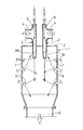
以下,本発明の実施の形態を,図1の図面について説明する。 An embodiment of the present invention will be described below with reference to the drawing of FIG.
この図1において,符号1は,縦型容器を示し,その上部における天井板2には,上下に延びる小径のガス導入ノズル管3の複数本が,その下端におけるノズル部3aを当該縦型容器1内に突出するようにして固着され,この各ガス導入ノズル管3の上部には,当該ガス導入ノズル管3内への排ガス導入口4が接続されているほか,前記各ガス導入ノズル管3の上端には,空気又は水を当該ガス導入ノズル管3の内部を通って前記ノズル部3aの内部に噴出するようにした詰まり清掃用ノズル5が設けられている。
In FIG. 1,
一方,前記縦型容器1の下部には,ガス出口6が設けられており,更に,この縦型容器1には,前記各ガス導入ノズル管3の下端におけるノズル部3aの外側に対して水を噴出するようにした水洗浄用ノズル7が設けられているほか,当該縦型容器1内の全域にわたって水を噴霧するようにしたスプレーノズル8の多数個が設けられている。
On the other hand, a
この構成において,排ガスは,小径の各ガス導入ノズル管3内に,排ガス導入口4が流入し,その下端におけるノズル部3aから縦型容器1内に噴出し,この縦型容器1内において,各水洗浄用ノズル7及び各スプレーノズル8から噴出される水と直接接触することにより洗浄されたのち,ガス出口6から排出される。
In this configuration, the exhaust gas flows into the small diameter gas
この場合において,前記ガス導入ノズル管3は,複数本の小径であることにより,その下端のノズル部3aにおける排ガスの流れ速度を,圧力損失の大幅な増大を招来することなく早くでき,しかも,このノズル部3aが,縦型容器1内に下向きに突出していることにより,前記各ガス導入ノズル管3の内部が,縦型容器1と同様に水分を多く含む雰囲気になることを回避できるから,この各ガス導入ノズル管3内に粉末状固形物にて詰まりが発生することを確実に低減できる。
In this case, since the gas
また,前記各ガス導入ノズル管3の下端におけるノズル部3aの外側には,前記水洗浄用ノズル7から水が吹き付けられていることにより,このノズル部3aの外側に,粉末状固形物が付着・堆積することを阻止できる。
Further, water is sprayed from the
そして,前記各ガス導入ノズル管3の内部に,粉末状固形物による詰まりが発生した場合には,その上端における詰まり清掃用ノズル5から空気又は水を高い圧力で噴射することにより,内部に付着・堆積した粉末状固形物を容易に除去することができる。
When clogging with powdered solids occurs inside each gas
この場合,前記詰まり清掃用ノズル5からの空気又は水の噴射は,詰まりが発生したときに行うことに限らず,適宜時間ごとの間隔で,一定の時間の間のだけ行うように構成しても良いのである。 In this case, the injection of air or water from the clogging cleaning nozzle 5 is not limited to being performed when clogging occurs, and is configured to be performed only at a certain time interval at an appropriate time interval. Is also good.
1 縦型容器
3 ガス導入ノズル管
3a ノズル部
4 排ガス導入口
5 詰まり清掃用ノズル
6 ガス出口
7 水洗浄用ノズル
8 スプレーノズル
DESCRIPTION OF
Claims (2)
前記排ガス導入管路は,下端にノズル部を備えた複数本の小径のガス導入ノズル管にて構成され,この各ガス導入ノズル管の下端におけるノズル部は,前記縦型容器内に,下向きに突出しており,更に,前記ガス導入ノズル管には,当該ガス導入ノズル管の内部を通って,その下端における前記ノズル部内に水又は空気を噴出するようにした詰まり清掃用ノズルが設けられていることを特徴とする排ガスの水洗浄装置。 In the water cleaning device that exhausts the exhaust gas introduced from the exhaust gas introduction pipe into the upper part of the vertical container in direct contact with water in the vertical container, and then discharges it from the gas outlet at the lower part,
The exhaust gas inlet pipe is composed of a plurality of small-diameter gas injection nozzle pipe having a nozzle portion at the lower end, the nozzle section at the lower end of each gas injection nozzle pipe, the vertical vessel, downwardly Further, the clogging cleaning nozzle is provided in the gas introduction nozzle pipe so as to eject water or air into the nozzle portion at the lower end thereof through the inside of the gas introduction nozzle pipe. water cleaning device of the exhaust gas, characterized in that there.
Priority Applications (1)
| Application Number | Priority Date | Filing Date | Title |
|---|---|---|---|
| JP2004366642A JP4518556B2 (en) | 2004-12-17 | 2004-12-17 | Exhaust water cleaning equipment |
Applications Claiming Priority (1)
| Application Number | Priority Date | Filing Date | Title |
|---|---|---|---|
| JP2004366642A JP4518556B2 (en) | 2004-12-17 | 2004-12-17 | Exhaust water cleaning equipment |
Publications (3)
| Publication Number | Publication Date |
|---|---|
| JP2006167664A JP2006167664A (en) | 2006-06-29 |
| JP2006167664A5 JP2006167664A5 (en) | 2008-02-07 |
| JP4518556B2 true JP4518556B2 (en) | 2010-08-04 |
Family
ID=36668966
Family Applications (1)
| Application Number | Title | Priority Date | Filing Date |
|---|---|---|---|
| JP2004366642A Expired - Fee Related JP4518556B2 (en) | 2004-12-17 | 2004-12-17 | Exhaust water cleaning equipment |
Country Status (1)
| Country | Link |
|---|---|
| JP (1) | JP4518556B2 (en) |
Families Citing this family (2)
| Publication number | Priority date | Publication date | Assignee | Title |
|---|---|---|---|---|
| DE202008012958U1 (en) | 2007-10-01 | 2009-05-20 | Iseli Umwelt & Heiztechnik Ag | Apparatus for washing flue gas |
| CN102213543B (en) * | 2010-12-15 | 2014-04-30 | 中国神华能源股份有限公司 | Dust collection device for vibration bed mixed flow dryer |
Citations (4)
| Publication number | Priority date | Publication date | Assignee | Title |
|---|---|---|---|---|
| JPS4857278A (en) * | 1971-11-17 | 1973-08-11 | ||
| JPH09262433A (en) * | 1996-03-28 | 1997-10-07 | Kureha Chem Ind Co Ltd | Cooling absorber for high temperature harmful gas and method thereof |
| JP2001259358A (en) * | 2000-03-16 | 2001-09-25 | Sumitomo Seika Chem Co Ltd | Exhaust gas treatment device |
| JP2002134419A (en) * | 2000-10-24 | 2002-05-10 | Shin Etsu Handotai Co Ltd | Method and system for processing exhaust gas |
-
2004
- 2004-12-17 JP JP2004366642A patent/JP4518556B2/en not_active Expired - Fee Related
Patent Citations (4)
| Publication number | Priority date | Publication date | Assignee | Title |
|---|---|---|---|---|
| JPS4857278A (en) * | 1971-11-17 | 1973-08-11 | ||
| JPH09262433A (en) * | 1996-03-28 | 1997-10-07 | Kureha Chem Ind Co Ltd | Cooling absorber for high temperature harmful gas and method thereof |
| JP2001259358A (en) * | 2000-03-16 | 2001-09-25 | Sumitomo Seika Chem Co Ltd | Exhaust gas treatment device |
| JP2002134419A (en) * | 2000-10-24 | 2002-05-10 | Shin Etsu Handotai Co Ltd | Method and system for processing exhaust gas |
Also Published As
| Publication number | Publication date |
|---|---|
| JP2006167664A (en) | 2006-06-29 |
Similar Documents
| Publication | Publication Date | Title |
|---|---|---|
| JP2009539579A (en) | Wet electrostatic precipitator | |
| TWI739309B (en) | Exhaust Hazardous Substance Removal Unit | |
| CN100463106C (en) | Semiconductor apparatus and cleaning unit thereof | |
| JP5297982B2 (en) | Wet venturi scrubber | |
| JP4518556B2 (en) | Exhaust water cleaning equipment | |
| JP5461236B2 (en) | Semiconductor substrate processing equipment | |
| KR20200041797A (en) | Abatement apparatus, method for exchanging a piping portion of abatement apparatus, and method for cleaning a piping of abatement apparatus | |
| JP2006269517A (en) | Substrate treatment apparatus and method therefor | |
| JP2013071077A (en) | Cleaning device and cleaning method of painting gun | |
| JP2003209337A (en) | Cleaning method for developing apparatus for printed wiring board | |
| JP6030360B2 (en) | Oil mist collector | |
| JP4300030B2 (en) | Cleaning device and method for cleaning gases | |
| TWI830789B (en) | Detoxifying apparatus, method for replacing piping section of detoxifying apparatus, and method for cleaning pipes of detoxifying apparatus | |
| CN216935239U (en) | Chemical water washing separator | |
| CN216064782U (en) | Environment-friendly welding gas cleaning structure | |
| CN213699283U (en) | Wet dust collector with pipeline washing unit | |
| CN218188727U (en) | Power plant dust removal system | |
| CN214972762U (en) | Defogging dust removal mechanism and desulfurizing tower in desulfurizing tower | |
| JP3917812B2 (en) | Exhaust system | |
| JP2004057968A (en) | Separation/recovery equipment for atomized coating material and the like | |
| JPH02144116A (en) | Exhaust gas treatment device | |
| JP2009247983A (en) | Regeneration method of ceramic filter | |
| CN206509282U (en) | A kind of vacuum filter high-pressure cleaning device | |
| JPH0623582Y2 (en) | Yarn fluid treatment equipment | |
| JPH0340336Y2 (en) |
Legal Events
| Date | Code | Title | Description |
|---|---|---|---|
| A521 | Written amendment |
Free format text: JAPANESE INTERMEDIATE CODE: A523 Effective date: 20071214 |
|
| A621 | Written request for application examination |
Free format text: JAPANESE INTERMEDIATE CODE: A621 Effective date: 20071214 |
|
| A977 | Report on retrieval |
Free format text: JAPANESE INTERMEDIATE CODE: A971007 Effective date: 20090612 |
|
| A131 | Notification of reasons for refusal |
Free format text: JAPANESE INTERMEDIATE CODE: A131 Effective date: 20090701 |
|
| A521 | Written amendment |
Free format text: JAPANESE INTERMEDIATE CODE: A523 Effective date: 20090828 |
|
| TRDD | Decision of grant or rejection written | ||
| A01 | Written decision to grant a patent or to grant a registration (utility model) |
Free format text: JAPANESE INTERMEDIATE CODE: A01 Effective date: 20100512 |
|
| A01 | Written decision to grant a patent or to grant a registration (utility model) |
Free format text: JAPANESE INTERMEDIATE CODE: A01 |
|
| A61 | First payment of annual fees (during grant procedure) |
Free format text: JAPANESE INTERMEDIATE CODE: A61 Effective date: 20100517 |
|
| FPAY | Renewal fee payment (event date is renewal date of database) |
Free format text: PAYMENT UNTIL: 20130528 Year of fee payment: 3 |
|
| R150 | Certificate of patent or registration of utility model |
Ref document number: 4518556 Country of ref document: JP Free format text: JAPANESE INTERMEDIATE CODE: R150 Free format text: JAPANESE INTERMEDIATE CODE: R150 |
|
| LAPS | Cancellation because of no payment of annual fees |