JP4514502B2 - Wind turbine for wind power generation - Google Patents
Wind turbine for wind power generation Download PDFInfo
- Publication number
- JP4514502B2 JP4514502B2 JP2004125695A JP2004125695A JP4514502B2 JP 4514502 B2 JP4514502 B2 JP 4514502B2 JP 2004125695 A JP2004125695 A JP 2004125695A JP 2004125695 A JP2004125695 A JP 2004125695A JP 4514502 B2 JP4514502 B2 JP 4514502B2
- Authority
- JP
- Japan
- Prior art keywords
- blade
- fixed
- vertical rotation
- power generation
- hub
- Prior art date
- Legal status (The legal status is an assumption and is not a legal conclusion. Google has not performed a legal analysis and makes no representation as to the accuracy of the status listed.)
- Expired - Fee Related
Links
Images


Classifications
-
- Y—GENERAL TAGGING OF NEW TECHNOLOGICAL DEVELOPMENTS; GENERAL TAGGING OF CROSS-SECTIONAL TECHNOLOGIES SPANNING OVER SEVERAL SECTIONS OF THE IPC; TECHNICAL SUBJECTS COVERED BY FORMER USPC CROSS-REFERENCE ART COLLECTIONS [XRACs] AND DIGESTS
- Y02—TECHNOLOGIES OR APPLICATIONS FOR MITIGATION OR ADAPTATION AGAINST CLIMATE CHANGE
- Y02E—REDUCTION OF GREENHOUSE GAS [GHG] EMISSIONS, RELATED TO ENERGY GENERATION, TRANSMISSION OR DISTRIBUTION
- Y02E10/00—Energy generation through renewable energy sources
- Y02E10/70—Wind energy
- Y02E10/74—Wind turbines with rotation axis perpendicular to the wind direction
Description
この発明は、風力発電用風車に関するもので、更に詳細には、発電機に連結される垂直回転軸を中心として一定角度ごとに複数設けられるブレードを具備する垂直型の風力発電用風車に関するものである。 The present invention relates to a wind turbine for wind power generation, and more particularly to a vertical wind turbine for wind power generation including a plurality of blades provided at a predetermined angle around a vertical rotation shaft connected to a generator. is there.
従来のこの種の垂直型の風力発電用風車として、ブレードを、アルミニウム合金やプラスチック製の薄板状の素材を曲げて流線形の翼形に形成すると共に、翼弦に対して垂直回転軸側が翼弦長の前縁側を残して後縁側を切り欠いて形成したものが知られている(例えば、特許文献1参照)。 As a conventional wind turbine for this type of wind power generation, the blade is formed into a streamlined airfoil by bending a thin plate material made of aluminum alloy or plastic, and the vertical rotating shaft side of the blade chord is the blade What formed the notch of the rear edge side leaving the front edge side of a chord length is known (for example, refer patent document 1).
上記の風力発電用風車によれば、低いレイノルズ数で高い揚力係数を有するブレードの一部の翼弦に対して回転軸側の後縁部に切欠部が形成されているので、ブレードは後方から風を受けて回転すると、切欠部によってブレードに大きな空気抵抗が生じるので、サボニウス型(半円筒形片寄りカップ型)風車効果によってブレードに回転モーメントが発生して、風車の起動トルクが発生する。その結果、風車を発電効率よく回転させることができる。
しかしながら、上記特許第3451085号公報記載の風力発電用風車においては、ブレードは、アルミニウム合金やプラスチック製の薄板状の素材を曲げて流線形の翼形に形成され、ブレード内に断面略コ字状の支持桁を嵌挿すると共にリベットや接着剤によって固定されている。また、支持桁には、ストラット支持金具が装着され、このストラット支持金具により回転軸から放射状に延びる支持ストラットの端部を固定する構造となっている。 However, in the wind turbine for wind power generation described in Japanese Patent No. 3451085, the blade is formed into a streamlined airfoil by bending a thin plate material made of aluminum alloy or plastic, and the cross-section is substantially U-shaped in the blade. The support girders are inserted and fixed with rivets or adhesives. The support girder is provided with a strut support fitting, and the strut support fitting fixes the ends of the support struts extending radially from the rotation shaft.
したがって、上記特許第3451085号公報記載のものにおいては、構成部材が多い上、構成部材同士の位置決めに手間がかかり、組立て作業が面倒であるという問題があった。また、回転軸と支持ストラットとの固定については具体的にされていないが、固定手段が溶接やねじ結合のいずれであっても、位置決めに細心の注意が必要であり、特に、溶接の場合は、位置決めが面倒な上、固定作業が面倒であるという問題がある。更には、ブレードの位置決めが不十分であると、発電効率の低下を招く虞もある。 Therefore, in the thing of the said patent 3451085 gazette, there existed a problem that there were many component members, and it took time and effort for positioning of component members, and an assembly operation was troublesome. In addition, although the rotation shaft and the support strut are not specifically fixed, even if the fixing means is either welding or screw connection, careful attention is required for positioning, particularly in the case of welding. There are problems that positioning is troublesome and fixing work is troublesome. Furthermore, inadequate positioning of the blades may lead to a decrease in power generation efficiency.
この発明は、上記事情に鑑みてなされたもので、構成部材の削減を図り、位置決め及び組立を容易にし、発電効率よく回転する風力発電用風車を提供することを目的とするものである。 The present invention has been made in view of the above circumstances, and an object thereof is to provide a wind turbine for wind power generation that reduces the number of components, facilitates positioning and assembly, and rotates with high power generation efficiency.
上記課題を解決するために、この発明の風力発電用風車は、発電機に連結されるパイプ状の垂直回転軸を中心として一定角度ごとに複数設けられるブレードと、各ブレードと上記垂直回転軸とを連結する複数の支持部材とを具備する風力発電用風車において、 上記ブレードは、流線形の翼形に形成されると共に、翼弦に対して上記垂直回転軸側が翼弦長の前縁側を残して後縁側が切り欠かれたブレード基部と、ブレード基部における切欠部の内方側を連結するリブと、上記ブレード基部とリブとで形成される凹所を一体に形成してなり、 上記支持部材は、一端が上記ブレードに当接し、該ブレード及び上記凹所内に嵌挿されるホルダを貫通するねじ部材によって固定されると共に、他端部が、上記垂直回転軸に装着されるハブにねじ部材によって固定され、 上記ハブは、垂直回転軸の中空部内に嵌挿固定される固定突部を有するハブ基部と、このハブ基部の外周に適宜角度をおいて放射状に突出する支持腕部とを具備し、上記支持腕部に、上記支持部材を保持する凹状受け溝を形成してなる、ことを特徴とする(請求項1)。 In order to solve the above-described problems, a wind turbine for wind power generation according to the present invention includes a plurality of blades provided at predetermined angles around a pipe-shaped vertical rotation shaft connected to a generator, each blade, and the vertical rotation shaft. The blade is formed in a streamlined airfoil, and the vertical rotation axis side with respect to the chord remains the leading edge side of the chord length. A blade base part whose rear edge side is cut off, a rib that connects the inner side of the notch part in the blade base part, and a recess that is formed by the blade base part and the rib. The one end abuts on the blade and is fixed by a screw member passing through the blade and a holder inserted into the recess, and the other end is fixed to the screw member on the hub mounted on the vertical rotation shaft. Fixed I, the hub includes a hub base having a fixed projection which is fitted secured in the hollow portion of the vertical shaft, and a support arm portion projecting radially at appropriate angles to the outer periphery of the hub base And a concave receiving groove for holding the support member is formed in the support arm portion (claim 1).
この発明において、上記支持部材は、断面略流線形状に形成されると共に、長手通しの貫通孔を形成し、かつ貫通孔にねじ部を設ける方が好ましい(請求項4)。 In the present invention, the support member is formed in a substantially streamlined shape, a through hole is formed in the through longitudinal and who provided the screw portion into the through-hole is preferable (claim 4).
また、この発明の風力発電用風車は、発電機に連結されるパイプ状の垂直回転軸を中心として一定角度ごとに複数設けられるブレードと、各ブレードと上記垂直回転軸とを連結する複数の支持部材とを具備する風力発電用風車において、 上記ブレードは、流線形の翼形に形成されると共に、翼弦に対して上記垂直回転軸側が翼弦長の前縁側を残して後縁側が切り欠かれたブレード基部と、ブレード基部における切欠部の内方側を連結するリブと、上記ブレード基部とリブとで形成される凹所を一体に形成してなり、 上記支持部材は、一端が上記ブレードに当接し、該ブレード及び上記凹所内に嵌挿されるホルダを貫通するねじ部材によって固定されると共に、他端部が、上記垂直回転軸に装着されるハブにねじ部材によって固定され、 上記ブレードに形成される凹所の開口部における一方のブレード基部側に、開口部の対向側に向かって隆起すると共に、開口部の外方側に向かって拡開傾斜面を有する第1の係止突起を形成し、他方のブレード基部の切欠部には、開口部の対向側に向かって膨隆する第2の係止突起を形成し、 上記ホルダは、一端に上記第1及び第2の係止突起にそれぞれ係合可能な係止段部を形成すると共に、他端の両側部には、先端に向かって狭小なテーパ面を形成してなる、ことを特徴とする(請求項2)。 In addition, the wind turbine for wind power generation according to the present invention includes a plurality of blades provided at fixed angles around a pipe-shaped vertical rotation shaft connected to the generator, and a plurality of supports for connecting each blade and the vertical rotation shaft. In the wind turbine for wind power generation comprising the member, the blade is formed in a streamlined airfoil shape, and the vertical rotation shaft side with respect to the chord is notched on the trailing edge side while leaving the leading edge side of the chord length. A blade base, a rib connecting the inner side of the notch in the blade base, and a recess formed by the blade base and the rib, and one end of the support member is the blade. Is fixed by a screw member that penetrates the blade and a holder that is inserted into the recess, and the other end is fixed by a screw member to a hub that is attached to the vertical rotation shaft, A first latch having a sloped surface that protrudes toward the opposite side of the opening on the one blade base side of the opening of the recess formed in the raid and that extends toward the outer side of the opening A protrusion is formed, and a second locking protrusion that bulges toward the opposite side of the opening is formed in the notch of the other blade base, and the holder has the first and second locking protrusions at one end. A locking step portion that can be respectively engaged with the protrusion is formed, and a tapered surface that is narrow toward the tip is formed on both side portions of the other end (claim 2) .
また、この発明の風力発電用風車は、発電機に連結されるパイプ状の垂直回転軸を中心として一定角度ごとに複数設けられるブレードと、各ブレードと上記垂直回転軸とを連結する複数の支持部材とを具備する風力発電用風車において、 上記ブレードは、流線形の翼形に形成されると共に、翼弦に対して上記垂直回転軸側が翼弦長の前縁側を残して後縁側が切り欠かれたブレード基部と、ブレード基部における切欠部の内方側を連結するリブと、上記ブレード基部とリブとで形成される凹所を一体に形成してなり、 上記支持部材は、一端が上記ブレードに当接し、該ブレード及び上記凹所内に嵌挿されるホルダを貫通するねじ部材によって固定されると共に、他端部が、上記垂直回転軸に装着されるハブにねじ部材によって固定され、 上記ハブは、垂直回転軸の中空部内に嵌挿固定される固定突部を有するハブ基部と、このハブ基部の外周に適宜角度をおいて放射状に突出する支持腕部とを具備し、上記支持腕部に、支持部材を保持する凹状受け溝を形成してなり、 上記ブレードに形成される凹所の開口部における一方のブレード基部側に、開口部の対向側に向かって隆起すると共に、開口部の外方側に向かって拡開傾斜面を有する第1の係止突起を形成し、他方のブレード基部の切欠部には、開口部の対向側に向かって膨隆する第2の係止突起を形成し、 上記ホルダは、一端に上記第1及び第2の係止突起にそれぞれ係合可能な係止段部を形成すると共に、他端の両側部には、先端に向かって狭小なテーパ面を形成してなる、ことを特徴とする(請求項3)。 In addition, the wind turbine for wind power generation according to the present invention includes a plurality of blades provided at fixed angles around a pipe-shaped vertical rotation shaft connected to the generator, and a plurality of supports for connecting each blade and the vertical rotation shaft. In the wind turbine for wind power generation comprising the member, the blade is formed in a streamlined airfoil shape, and the vertical rotation shaft side with respect to the chord is notched on the trailing edge side while leaving the leading edge side of the chord length. A blade base, a rib connecting the inner side of the notch in the blade base, and a recess formed by the blade base and the rib, and one end of the support member is the blade. Is fixed by a screw member that penetrates the blade and a holder that is inserted into the recess, and the other end is fixed by a screw member to a hub that is attached to the vertical rotation shaft, The hub comprises a hub base having a fixed protrusion that is fitted and fixed in the hollow part of the vertical rotation shaft, and a support arm that protrudes radially at an appropriate angle to the outer periphery of the hub base, A concave receiving groove for holding the support member is formed in the part, and the one side of the blade base in the opening of the recess formed in the blade is raised toward the opposite side of the opening, and the opening A first locking projection having an expanding inclined surface is formed toward the outer side of the second blade, and a second locking projection that bulges toward the opposite side of the opening is formed in the notch of the other blade base. The holder is formed with a locking step portion engageable with each of the first and second locking projections at one end, and a tapered surface narrowing toward the tip at both sides of the other end. by forming a, characterized in that (claim 3).
加えて、上記垂直回転軸、ブレード、支持部材及びホルダを、それぞれアルミニウム合金製押出形材にて形成し、上記ハブを、アルミニウム合金製鋳物にて形成する方が好ましい(請求項5)。 In addition, it is preferable that the vertical rotation shaft, the blade, the support member, and the holder are each formed of an aluminum alloy extruded shape, and the hub is formed of an aluminum alloy casting.
この発明によれば、上記のように構成されているので、以下のような効果が得られる。 According to this invention, since it is configured as described above, the following effects can be obtained.
(1)請求項1,2,3記載の発明によれば、ブレードは、流線形の翼形に形成されると共に、翼弦に対して垂直回転軸側が翼弦長の前縁側を残して後縁側が切り欠かれたブレード基部と、ブレード基部における切欠部の内方側を連結するリブと、ブレード基部とリブとで形成される凹所を一体に形成することにより、構成部材の削減が図れると共に、ブレードを軽量かつ強固にすることができる。また、支持部材は、一端がブレードに当接し、該ブレード及び上記凹所内に嵌挿されるホルダを貫通するねじ部材によって固定されると共に、他端部が、垂直回転軸に装着されるハブにねじ部材によって固定されるので、垂直回転軸に対するブレードの位置決めを容易にすることができ、正確に位置決めすることができる。したがって、発電効率の向上を図ることができる。
(1) According to the inventions of
(2)請求項4記載の発明によれば、支持部材は、断面略流線形状に形成されると共に、長手通しの貫通孔を形成し、かつ貫通孔にねじ部を設けるので、上記(1)に加えて更に形状及び重量による支持部材による空気抵抗を可及的に少なくすることができると共に、ブレードへの取付すなわちねじ部材の固定を容易にすることができる。
(2) According to the invention described in
(3)請求項1,3記載の発明によれば、ハブは、垂直回転軸の中空部内に嵌挿固定される固定突部を有するハブ基部と、このハブ基部の外周に適宜角度をおいて放射状に突出する支持腕部とを具備し、支持腕部に、支持部材を保持する凹状受け溝を形成することにより、上記(1)及び(2)に加えて更にハブと垂直回転軸の固定を容易かつ強固にすることができると共に、支持部材の固定を容易かつ強固にすることができる。 (3) According to the first and third aspects of the present invention, the hub has a hub base portion having a fixed projection portion fitted and fixed in the hollow portion of the vertical rotation shaft, and an appropriate angle between the outer periphery of the hub base portion. In addition to the above (1) and (2), the hub and the vertical rotation shaft can be further fixed by forming a support arm portion projecting radially and forming a concave receiving groove for holding the support member in the support arm portion. Can be easily and strengthened, and the fixing of the support member can be facilitated and strengthened.
(4)請求項2,3記載の発明によれば、ブレードに形成される凹所の開口部における一方のブレード基部側に、開口部の対向側に向かって隆起すると共に、開口部の外方側に向かって拡開傾斜面を有する第1の係止突起を形成し、他方のブレード基部の切欠部には、開口部の対向側に向かって膨隆する第2の係止突起を形成し、ホルダは、一端に第1及び第2の係止突起にそれぞれ係合可能な係止段部を形成すると共に、他端の両側部には、先端に向かって狭小なテーパ面を形成することにより、ホルダを開口部の開口方向から容易に嵌挿することができると共に、ホルダを凹所内に強固に嵌挿することができる。したがって、上記(1)〜(3)に加えて更に支持部材とブレードとの位置決めを容易にすることができると共に、強固に固定することができる。 (4) According to the second and third aspects of the invention, one of the blade bases in the opening of the recess formed in the blade protrudes toward the opposite side of the opening, and the outside of the opening. Forming a first locking projection having an expanding inclined surface toward the side, and forming a second locking projection bulging toward the opposite side of the opening in the notch of the other blade base; The holder is formed with a locking step portion that can be engaged with the first and second locking projections at one end, and a tapered surface that is narrow toward the tip at both sides of the other end. The holder can be easily inserted from the opening direction of the opening, and the holder can be firmly inserted into the recess. Therefore, in addition to the above (1) to (3), the positioning of the support member and the blade can be facilitated and can be firmly fixed.
(5)請求項5記載の発明によれば、垂直回転軸、ブレード、支持部材及びホルダを、それぞれアルミニウム合金製押出形材にて形成し、ハブを、アルミニウム合金製鋳物にて形成することにより、上記(1)〜(4)に加えて更に風車全体を軽量にすることができ、発電効率の向上を図ることができる。
(5) According to the invention described in
以下に、この発明の最良の実施形態を添付図面に基づいて詳細に説明する。 DESCRIPTION OF THE PREFERRED EMBODIMENTS Hereinafter, the best embodiment of the present invention will be described in detail with reference to the accompanying drawings.
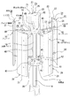
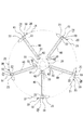
図1は、この発明に係る風力発電用風車の全体を示す斜視図、図2は、上記風車の概略側面図、図3は、上記風車の平面図である。 FIG. 1 is a perspective view showing an entire wind turbine for wind power generation according to the present invention, FIG. 2 is a schematic side view of the wind turbine, and FIG. 3 is a plan view of the wind turbine.
この発明に係る発電用風車は、図1ないし図3に示すように、発電機1に連結されるパイプ状の垂直回転軸10(以下に、支柱パイプ10という)を中心として一定角度ごとに複数例えば5個設けられるブレード20と、支柱パイプ10の上下端部に装着される2個のハブ30と、これらハブ30を介して各ブレード20と支柱パイプ10とを連結する複数例えば5本の支持部材40(以下に、ストラット40という)とで主に構成されている。
As shown in FIGS. 1 to 3, the power generation wind turbine according to the present invention includes a plurality of pipe-shaped vertical rotating shafts 10 (hereinafter referred to as column pipes 10) connected to the
上記ブレード20は、アルミニウム合金製押出形材にて形成されている。このブレード20は、低いレイノルズ数で高い揚力係数を有するように流線形の翼形に形成されると共に、翼弦に対して回転軸側が翼弦長の前縁側を残して後縁側が切り欠かれたブレード基部21と、ブレード基部21における切欠部22の内方側を連結するリブ23と、ブレード基部21とリブ23とで形成される凹所24を一体に形成してなる。
The
このように形成されるブレード20は、軽量かつ強固に形成され、また、ブレードの一部の翼弦に対して回転軸側の後縁部に切欠部22が形成されているので、ブレード20が後方から風を受けて回転すると、切欠部22によってブレード20に大きな空気抵抗が生じ、サボニウス型(半円筒形片寄りカップ型)風車効果によってブレード20に回転モーメントが発生して、風車の起動トルクを発生するようになっている。
The
上記ストラット40は、アルミニウム合金製押出形材にて形成されている。このストラット40は、、空気抵抗を可及的に少なくすべく断面略流線形状に形成されると共に、長手通しの貫通孔41が形成され、かつ貫通孔41の一端部に雌ねじ部42が形成(刻設)され、また、他端部には、長手方向と直交する方向にねじ孔43が2個刻設されている。
The
このように形成されるストラット40は、図4及び図5に示すように、一端がブレード20に当接し、該ブレード20及び凹所24内に嵌挿されるホルダ50を貫通してストラット40に設けられた雌ねじ部42にねじ結合するねじ部材例えば第1の固定ねじ61によって固定される。また、ストラット40の他端部は、ねじ部材例えば第2の固定ねじ62によってハブ30に固定されている。
As shown in FIGS. 4 and 5, the
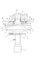
この場合、ハブ30は、アルミニウム合金製の鋳物にて形成されている。このハブ30は、図6に示すように、支柱パイプ10の中空部内に嵌挿されて、固定される円筒状の固定突部31を突設する略円盤状のハブ基部32と、このハブ基部32の外周に適宜角度をおいて放射状に突出する支持腕部33とを具備し、支持腕部33の上面又は下面に、ストラット40を保持する凹状の受け溝34が形成され、この受け溝34の底部に2個の貫通孔35が設けられている。
In this case, the
上記のように、支持腕部33の上面又は下面に、ストラット40を保持する受け溝34を形成すると共に、受け溝34の底部に貫通孔35を設けることにより、ストラット40の端部を受け溝34内にガタツキなく位置決めした状態で、貫通孔35を貫通する第2の固定ねじ62をストラット40に設けられたねじ孔43にねじ結合することによって固定することができる。
As described above, the receiving
なお、図6に示すように、支柱パイプ10の側部に設けられた透孔11を貫通する第3の固定ねじ63を、ハブ30の固定突部31に設けられたねじ孔31aにねじ結合することによって、支柱パイプ10とハブ30が固定される。
As shown in FIG. 6, the third fixing
また、ハブ基部32には、径の異なる2つの同心円上にそれぞれ一定角度(120度)をおいて3個の透孔36が設けられており、これら透孔36を貫通する取付ボルト37を発電機1のフランジ2に設けられたねじ孔3にねじ結合することで、大きさの異なる2種類の発電機1にハブ30を介して支柱パイプ10を連結することができるように構成されている(図6参照)。
The
この場合、上記発電機1は、固定シャフト4にベアリング(図示せず)を介在して回転胴体5を回転自在に装着してなり、固定シャフト4が支柱6に固定ボルト7によって固定されている。また、回転胴体5には、ブレーキディスク8が固定され、支柱6には、ブレーキシュー9が固定されている。なお、発電機1の電気ケーブル(図示せず)は、中空状の固定シャフト4内に配線されている。
In this case, the
また、上記ブレード20に形成される凹所24の開口部における一方のブレード基部側には、開口部25の対向側に向かって隆起すると共に、開口部25の外方側に向かって拡開傾斜面26aを有する第1の係止突起26が形成されている。また、他方のブレード基部21の切欠部22には、開口部25の対向側に向かって膨隆する断面略円弧状の第2の係止突起27が形成されている。
Also, one blade base side of the opening portion of the
一方、上記ホルダは、アルミニウム合金製押出形材を所定の寸法に切断したブロック状に形成されている。このホルダ50は、一端に第1及び第2の係止突起26,27にそれぞれ係合可能な係止段部51,52を形成すると共に、他端の両側部には、先端に向かって狭小なテーパ面53が形成されている。また、ホルダ50は、上記第1及び第2の係止突起27と狭小テーパ面53を設けた対向面と直交する対向面に取付孔54が貫通されている。
On the other hand, the holder is formed in a block shape obtained by cutting an extruded shape made of aluminum alloy into a predetermined dimension. The
このように形成されるホルダ50は、ブレード20に形成された凹所24の開口部側から狭小テーパ面53を押圧することにより、ブレード20自体の弾性により開口部25が拡開変形するので、凹所24内に容易に嵌挿することができる。また、ホルダ50の嵌挿後は、ブレード20の開口部25がスプリングバックによって元の状態に戻り、第1及び第2の係止突起26,27がそれぞれホルダ50に設けられた係止段部51,52に係合するので、凹所24内に強固に嵌挿される。
Since the
次に、上記のように構成されるこの発明に係る風力発電用風車の組立手順の一例について説明する。 Next, an example of an assembly procedure of the wind turbine for wind power generation according to the present invention configured as described above will be described.
まず、ブレード20の凹所24の開口部25側から凹所24内の所定箇所にホルダ50を嵌挿する。次に、ホルダ50が嵌挿された部位のブレード基部21に、ストラット40の雌ねじ部42が設けられた一端部を当接し、ブレード20の外側からブレード基部21及びホルダ50の取付孔54を貫通する第1の固定ねじ61を雌ねじ部42にねじ結合して、ブレード20とストラット40を固定する。次に、ストラット40の他端部を、支柱パイプ10の上端又は下端に固定されたハブ30の支持腕部33に設けられた受け溝34にセットし、受け溝34に設けられた貫通孔35を貫通する第2の固定ねじ62をストラット40に設けられたねじ孔43にねじ結合して、ストラット40とハブ30とを固定する。
First, the
なお、上記説明では、ストラット40とブレード20を固定した後、ストラット40とハブ30を固定する場合について説明したが、取付手順を逆にしてもよい。すなわち、ストラット40とハブ30を固定した後に、ストラット40とブレード20を固定してもよい。
In the above description, the case where the
上記のようにして、各ブレード20の上下の2箇所と2個のハブ30をそれぞれストラット40によって固定して風車を組み立てる。
As described above, the wind turbine is assembled by fixing the two upper and lower portions of each
上記のようにして組み立てられた風車は、下部のハブ30のハブ基部32に設けられた透孔36を貫通する取付ボルト37を発電機1のフランジ2に設けられたねじ孔3にねじ結合することにより、支柱パイプ10と発電機1が連結される。その後、発電機1の固定シャフト4を支柱6に固定して、使用可能な状態に設置される。
In the wind turbine assembled as described above, the mounting
なお、上記実施形態では、ブレード20が5個設けられる場合について説明したが、ブレード20の数は5個である必要はなく、4個あるいは6個以上であってもよい。
In the above embodiment, the case where five
1 発電機
10 支柱パイプ(垂直回転軸)
20 ブレード
21 ブレード基部
22 切欠部
23 リブ
24 凹所
25 開口部
26 第1の係止突起
26a 拡開傾斜面
27 第2の係止突起
30 ハブ
31 固定突部
32 ハブ基部
33 支持腕部
34 受け溝
40 ストラット(支持部材)
41 貫通孔
42 雌ねじ部
43 ねじ孔
50 ホルダ
51,52 係止段部
53 狭小テーパ面
54 取付孔
61 第1の固定ねじ(ねじ部材)
62 第2の固定ねじ(ねじ部材)
1
20
41 Through-
62 Second fixing screw (screw member)
Claims (5)
上記ブレードは、流線形の翼形に形成されると共に、翼弦に対して上記垂直回転軸側が翼弦長の前縁側を残して後縁側が切り欠かれたブレード基部と、ブレード基部における切欠部の内方側を連結するリブと、上記ブレード基部とリブとで形成される凹所を一体に形成してなり、
上記支持部材は、一端が上記ブレードに当接し、該ブレード及び上記凹所内に嵌挿されるホルダを貫通するねじ部材によって固定されると共に、他端部が、上記垂直回転軸に装着されるハブにねじ部材によって固定され、
上記ハブは、垂直回転軸の中空部内に嵌挿固定される固定突部を有するハブ基部と、このハブ基部の外周に適宜角度をおいて放射状に突出する支持腕部とを具備し、上記支持腕部に、上記支持部材を保持する凹状受け溝を形成してなる、ことを特徴とする風力発電用風車。 In a wind turbine for wind power generation comprising a plurality of blades provided at fixed angles around a pipe-shaped vertical rotation shaft connected to a generator, and a plurality of support members for connecting each blade and the vertical rotation shaft,
The blade is formed in a streamlined airfoil shape, and a blade base portion in which the vertical rotation axis side with respect to the chord is cut away on the trailing edge side while leaving a leading edge side of the chord length, and a notch portion in the blade base portion A rib for connecting the inner side of the blade, and a recess formed by the blade base and the rib are integrally formed,
One end of the support member is in contact with the blade, and is fixed by a screw member that passes through the blade and a holder that is inserted into the recess, and the other end is fixed to a hub that is mounted on the vertical rotation shaft. Fixed by a screw member ,
The hub includes a hub base portion having a fixed protrusion portion that is fitted and fixed in a hollow portion of a vertical rotation shaft, and a support arm portion that protrudes radially at an appropriate angle to the outer periphery of the hub base portion. A wind turbine for wind power generation , wherein a concave receiving groove for holding the support member is formed in an arm portion .
上記ブレードは、流線形の翼形に形成されると共に、翼弦に対して上記垂直回転軸側が翼弦長の前縁側を残して後縁側が切り欠かれたブレード基部と、ブレード基部における切欠部の内方側を連結するリブと、上記ブレード基部とリブとで形成される凹所を一体に形成してなり、
上記支持部材は、一端が上記ブレードに当接し、該ブレード及び上記凹所内に嵌挿されるホルダを貫通するねじ部材によって固定されると共に、他端部が、上記垂直回転軸に装着されるハブにねじ部材によって固定され、
上記ブレードに形成される凹所の開口部における一方のブレード基部側に、開口部の対向側に向かって隆起すると共に、開口部の外方側に向かって拡開傾斜面を有する第1の係止突起を形成し、他方のブレード基部の切欠部には、開口部の対向側に向かって膨隆する第2の係止突起を形成し、
上記ホルダは、一端に上記第1及び第2の係止突起にそれぞれ係合可能な係止段部を形成すると共に、他端の両側部には、先端に向かって狭小なテーパ面を形成してなる、ことを特徴とする風力発電用風車。 In a wind turbine for wind power generation comprising a plurality of blades provided at fixed angles around a pipe-shaped vertical rotation shaft connected to a generator, and a plurality of support members for connecting each blade and the vertical rotation shaft,
The blade is formed in a streamlined airfoil shape, and a blade base portion in which the vertical rotation axis side with respect to the chord is cut away on the trailing edge side while leaving a leading edge side of the chord length, and a notch portion in the blade base portion A rib for connecting the inner side of the blade, and a recess formed by the blade base and the rib are integrally formed,
One end of the support member is in contact with the blade, and is fixed by a screw member that passes through the blade and a holder that is inserted into the recess, and the other end is fixed to a hub that is mounted on the vertical rotation shaft. Fixed by a screw member,
A first engaging member that protrudes toward the opposite side of the opening on the one blade base side of the opening of the recess formed in the blade and has an expanding inclined surface toward the outer side of the opening. A stop protrusion is formed, and a second locking protrusion that bulges toward the opposite side of the opening is formed in the notch of the other blade base,
The holder has a locking step portion that can engage with the first and second locking protrusions at one end, and a tapered surface that narrows toward the tip at both sides of the other end. A wind turbine for wind power generation, characterized by
上記ブレードは、流線形の翼形に形成されると共に、翼弦に対して上記垂直回転軸側が翼弦長の前縁側を残して後縁側が切り欠かれたブレード基部と、ブレード基部における切欠部の内方側を連結するリブと、上記ブレード基部とリブとで形成される凹所を一体に形成してなり、The blade is formed in a streamlined airfoil shape, and a blade base portion in which the vertical rotation axis side with respect to the chord is cut away on the trailing edge side while leaving a leading edge side of the chord length, and a notch portion in the blade base portion A rib for connecting the inner side of the blade, and a recess formed by the blade base and the rib are integrally formed,
上記支持部材は、一端が上記ブレードに当接し、該ブレード及び上記凹所内に嵌挿されるホルダを貫通するねじ部材によって固定されると共に、他端部が、上記垂直回転軸に装着されるハブにねじ部材によって固定され、One end of the support member is in contact with the blade, and is fixed by a screw member that passes through the blade and a holder that is inserted into the recess, and the other end is fixed to a hub that is mounted on the vertical rotation shaft. Fixed by a screw member,
上記ハブは、垂直回転軸の中空部内に嵌挿固定される固定突部を有するハブ基部と、このハブ基部の外周に適宜角度をおいて放射状に突出する支持腕部とを具備し、上記支持腕部に、支持部材を保持する凹状受け溝を形成してなり、The hub includes a hub base portion having a fixed protrusion portion that is fitted and fixed in a hollow portion of a vertical rotation shaft, and a support arm portion that protrudes radially at an appropriate angle to the outer periphery of the hub base portion. A concave receiving groove for holding the support member is formed in the arm part,
上記ブレードに形成される凹所の開口部における一方のブレード基部側に、開口部の対向側に向かって隆起すると共に、開口部の外方側に向かって拡開傾斜面を有する第1の係止突起を形成し、他方のブレード基部の切欠部には、開口部の対向側に向かって膨隆する第2の係止突起を形成し、A first engaging member that protrudes toward the opposite side of the opening on the one blade base side of the opening of the recess formed in the blade and has an expanding inclined surface toward the outer side of the opening. A stop protrusion is formed, and a second locking protrusion that bulges toward the opposite side of the opening is formed in the notch of the other blade base,
上記ホルダは、一端に上記第1及び第2の係止突起にそれぞれ係合可能な係止段部を形成すると共に、他端の両側部には、先端に向かって狭小なテーパ面を形成してなる、ことを特徴とする風力発電用風車。The holder has a locking step portion that can engage with the first and second locking protrusions at one end, and a tapered surface that narrows toward the tip at both sides of the other end. A wind turbine for wind power generation, characterized by
上記支持部材は、断面略流線形状に形成されると共に、長手通しの貫通孔を形成し、かつ貫通孔にねじ部を設ける、ことを特徴とする風力発電用風車。 In the wind turbine for wind power generation according to any one of claims 1 to 3 ,
The wind turbine for wind power generation is characterized in that the support member is formed in a substantially streamline cross section, has a longitudinal through hole, and is provided with a screw portion in the through hole.
上記垂直回転軸、ブレード、支持部材及びホルダを、それぞれアルミニウム合金製押出形材にて形成し、上記ハブを、アルミニウム合金製鋳物にて形成してなる、ことを特徴とする風力発電用風車。 In the wind turbine for wind power generation according to any one of claims 1 to 4 ,
A wind turbine for wind power generation, wherein the vertical rotating shaft, the blade, the support member, and the holder are each formed of an extruded product made of an aluminum alloy, and the hub is formed of an aluminum alloy casting.
Priority Applications (1)
| Application Number | Priority Date | Filing Date | Title |
|---|---|---|---|
| JP2004125695A JP4514502B2 (en) | 2004-04-21 | 2004-04-21 | Wind turbine for wind power generation |
Applications Claiming Priority (1)
| Application Number | Priority Date | Filing Date | Title |
|---|---|---|---|
| JP2004125695A JP4514502B2 (en) | 2004-04-21 | 2004-04-21 | Wind turbine for wind power generation |
Publications (3)
| Publication Number | Publication Date |
|---|---|
| JP2005307850A JP2005307850A (en) | 2005-11-04 |
| JP2005307850A5 JP2005307850A5 (en) | 2007-05-24 |
| JP4514502B2 true JP4514502B2 (en) | 2010-07-28 |
Family
ID=35436906
Family Applications (1)
| Application Number | Title | Priority Date | Filing Date |
|---|---|---|---|
| JP2004125695A Expired - Fee Related JP4514502B2 (en) | 2004-04-21 | 2004-04-21 | Wind turbine for wind power generation |
Country Status (1)
| Country | Link |
|---|---|
| JP (1) | JP4514502B2 (en) |
Cited By (1)
| Publication number | Priority date | Publication date | Assignee | Title |
|---|---|---|---|---|
| JP2016156325A (en) * | 2015-02-25 | 2016-09-01 | 株式会社Lixil | Vertical shaft type windmill |
Families Citing this family (21)
| Publication number | Priority date | Publication date | Assignee | Title |
|---|---|---|---|---|
| WO2007064155A1 (en) * | 2005-11-30 | 2007-06-07 | Geumpoong Energy | Aerogenerator |
| CN1873220A (en) * | 2006-06-28 | 2006-12-06 | 严强 | Method for installing blades and wind wheel of wind driven generator with vertical axis |
| US8322035B2 (en) | 2006-03-29 | 2012-12-04 | Yan Qiang | Vertical axis wind turbine and method of installing blades therein |
| JP4647573B2 (en) * | 2006-10-19 | 2011-03-09 | 菊川工業株式会社 | Wind generator blade |
| EP2236819A4 (en) * | 2008-01-25 | 2011-04-27 | Noguchi Tsuneo | Vertical axis wind turbine |
| GB0810094D0 (en) * | 2008-06-03 | 2008-07-09 | Slipstream Energy Ltd | Wind turbine blades |
| JP5506033B2 (en) * | 2008-07-17 | 2014-05-28 | のあい株式会社 | Wind turbine for wind power generation and manufacturing method thereof |
| KR101005473B1 (en) | 2008-10-21 | 2011-01-05 | 주식회사 윈젠 | A manufacturing method of blade for wind power generation with vertical axis |
| JP2011094582A (en) * | 2009-11-02 | 2011-05-12 | Keiyo Aaki Metal Kk | Wind power generation unit and system |
| KR101155964B1 (en) * | 2009-12-24 | 2012-06-18 | 에너진(주) | apparatus for wind power generation |
| US8016544B1 (en) * | 2010-03-08 | 2011-09-13 | Nguyen Huy T | Vertical windmill |
| KR100999320B1 (en) * | 2010-04-23 | 2010-12-08 | 손정희 | Wind blade for wind generator and manufacturing method thereof |
| JP5904352B2 (en) * | 2010-09-14 | 2016-04-13 | 株式会社Winpro | Wind power generator using the planetary magnet gear drive generator |
| KR101055866B1 (en) | 2011-03-31 | 2011-08-11 | 씨에이코리아(주) | Vertical-axis wind power generator which have separated hub |
| CN103527401A (en) * | 2013-10-15 | 2014-01-22 | 沈阳航空航天大学 | Method of vertical-shaft wind turbine for improving wind energy utilization through groove opening technology |
| JP5731048B1 (en) * | 2014-04-04 | 2015-06-10 | 豊 根本 | Wind turbine blades and struts for vertical axis wind power generators |
| JP6505990B2 (en) * | 2014-07-08 | 2019-04-24 | 国立大学法人鳥取大学 | Darrieus type vertical axis windmill |
| CN105673321A (en) * | 2016-03-29 | 2016-06-15 | 范德义 | Multi-column tower type multifunctional turbine blade |
| CN106505789A (en) * | 2016-12-20 | 2017-03-15 | 田曙光 | Electromotor lever and electromotor |
| JP2023137639A (en) * | 2022-03-18 | 2023-09-29 | 日軽金アクト株式会社 | Supporting leg fixing structure of vertical axis wind turbine |
| JP2023137638A (en) * | 2022-03-18 | 2023-09-29 | 日軽金アクト株式会社 | Blade fixing structure of vertical axis wind turbine |
Citations (3)
| Publication number | Priority date | Publication date | Assignee | Title |
|---|---|---|---|---|
| JPS57191871U (en) * | 1981-05-30 | 1982-12-04 | ||
| WO2003074868A1 (en) * | 2002-03-01 | 2003-09-12 | Ebara Corporation | Vertical axis windmill |
| JP3451085B1 (en) * | 2002-09-20 | 2003-09-29 | 常夫 野口 | Windmill for wind power generation |
-
2004
- 2004-04-21 JP JP2004125695A patent/JP4514502B2/en not_active Expired - Fee Related
Patent Citations (3)
| Publication number | Priority date | Publication date | Assignee | Title |
|---|---|---|---|---|
| JPS57191871U (en) * | 1981-05-30 | 1982-12-04 | ||
| WO2003074868A1 (en) * | 2002-03-01 | 2003-09-12 | Ebara Corporation | Vertical axis windmill |
| JP3451085B1 (en) * | 2002-09-20 | 2003-09-29 | 常夫 野口 | Windmill for wind power generation |
Cited By (1)
| Publication number | Priority date | Publication date | Assignee | Title |
|---|---|---|---|---|
| JP2016156325A (en) * | 2015-02-25 | 2016-09-01 | 株式会社Lixil | Vertical shaft type windmill |
Also Published As
| Publication number | Publication date |
|---|---|
| JP2005307850A (en) | 2005-11-04 |
Similar Documents
| Publication | Publication Date | Title |
|---|---|---|
| JP4514502B2 (en) | Wind turbine for wind power generation | |
| CN100410531C (en) | Support arm installation structure for vertical axis wind wheel, and vertical axis wind wheel | |
| US4275993A (en) | Composite fan blade assembly | |
| TW201104071A (en) | Vertical axis wind turbine generator | |
| JP4647573B2 (en) | Wind generator blade | |
| JPWO2010007684A1 (en) | Wind turbine for wind power generation and manufacturing method thereof | |
| JP2019143615A (en) | Arched rib for turbine | |
| US20160153424A1 (en) | Mountable wing tip device for mounting on a rotor blade of a wind turbine arrangement | |
| JP2019210912A (en) | Vertical shaft windmill and wind power generator | |
| US10422314B2 (en) | Spiral blade unit and wind generator and blade connector for the unit | |
| JP2005030375A (en) | Vertical shaft type wind power generator and manufacturing method of blade | |
| EP1571345B1 (en) | Fan | |
| JP6465783B2 (en) | Wings for wind power generation | |
| WO2022059624A1 (en) | Vertical shaft wind turbine and vertical shaft wind turbine generator | |
| EP3168457B1 (en) | Wind turbine with blades with a coning angle | |
| KR20090127629A (en) | Wing assembly for wind power generation | |
| JP2005240632A (en) | Windmill for wind power generation device | |
| KR200418922Y1 (en) | Aerogenerator | |
| US4025233A (en) | Rotor for wind-driven machine | |
| WO2023176309A1 (en) | Blade fixing structure for vertical axis wind turbine | |
| KR101555510B1 (en) | Horizontal axis wind turbine having extruding blade | |
| KR20070098301A (en) | Aerogenerator | |
| JP4293835B2 (en) | Wind power generator using pinwheel windmill | |
| JP2007107448A (en) | Vertical type windmill | |
| JPS6214397Y2 (en) |
Legal Events
| Date | Code | Title | Description |
|---|---|---|---|
| A521 | Written amendment |
Free format text: JAPANESE INTERMEDIATE CODE: A523 Effective date: 20070330 |
|
| A621 | Written request for application examination |
Free format text: JAPANESE INTERMEDIATE CODE: A621 Effective date: 20070330 |
|
| A977 | Report on retrieval |
Free format text: JAPANESE INTERMEDIATE CODE: A971007 Effective date: 20091119 |
|
| A131 | Notification of reasons for refusal |
Free format text: JAPANESE INTERMEDIATE CODE: A131 Effective date: 20091124 |
|
| A521 | Written amendment |
Free format text: JAPANESE INTERMEDIATE CODE: A523 Effective date: 20100120 |
|
| A711 | Notification of change in applicant |
Free format text: JAPANESE INTERMEDIATE CODE: A711 Effective date: 20100215 |
|
| A521 | Written amendment |
Free format text: JAPANESE INTERMEDIATE CODE: A821 Effective date: 20100215 |
|
| TRDD | Decision of grant or rejection written | ||
| A01 | Written decision to grant a patent or to grant a registration (utility model) |
Free format text: JAPANESE INTERMEDIATE CODE: A01 Effective date: 20100511 |
|
| A01 | Written decision to grant a patent or to grant a registration (utility model) |
Free format text: JAPANESE INTERMEDIATE CODE: A01 |
|
| A61 | First payment of annual fees (during grant procedure) |
Free format text: JAPANESE INTERMEDIATE CODE: A61 Effective date: 20100511 |
|
| R150 | Certificate of patent or registration of utility model |
Free format text: JAPANESE INTERMEDIATE CODE: R150 |
|
| FPAY | Renewal fee payment (event date is renewal date of database) |
Free format text: PAYMENT UNTIL: 20130521 Year of fee payment: 3 |
|
| LAPS | Cancellation because of no payment of annual fees |