JP4512736B2 - Pachinko machine - Google Patents
Pachinko machine Download PDFInfo
- Publication number
- JP4512736B2 JP4512736B2 JP2005045537A JP2005045537A JP4512736B2 JP 4512736 B2 JP4512736 B2 JP 4512736B2 JP 2005045537 A JP2005045537 A JP 2005045537A JP 2005045537 A JP2005045537 A JP 2005045537A JP 4512736 B2 JP4512736 B2 JP 4512736B2
- Authority
- JP
- Japan
- Prior art keywords
- frame
- door
- main body
- locking
- body frame
- Prior art date
- Legal status (The legal status is an assumption and is not a legal conclusion. Google has not performed a legal analysis and makes no representation as to the accuracy of the status listed.)
- Expired - Fee Related
Links
Images


Description
この発明は、前側にガラス扉のような開閉扉が開閉可能に装着されたパチンコ機に関する。 The present invention, door, such as glass door about the openable and closable loaded pachinko machine front.
この種の遊技機(例えば、パチンコ機)において、本体枠(前枠、前面枠等とも呼ばれる)の前面の一側に扉開閉用ヒンジ機構によってガラス扉が開閉可能に装着されるようになっている。
また、本体枠後面の自由端側には、ガラス扉を閉じ状態に施錠する扉施錠具を有する施錠装置が配設されるるとともに、本体枠の自由端寄り部分には、扉施錠具に対応する位置においてフック挿通孔が形成されている。
一方、ガラス扉の後面の自由端側には扉施錠フックが後方に向けて突出されている。
そして、ガラス扉を閉じたときには、その後面の扉施錠フックが本体枠を貫通して施錠装置の扉用施錠金具に係脱可能に係合し、これによってガラス扉を閉じ状態に施錠するように構成されたものが知られている(例えば、特許文献1参照)。
In addition, a locking device having a door locking device that locks the glass door in a closed state is disposed on the free end side of the rear surface of the main body frame, and a portion closer to the free end of the main body frame corresponds to the door locking device. A hook insertion hole is formed at the position.
On the other hand, a door locking hook projects rearward from the free end of the rear surface of the glass door.
And when the glass door is closed, the door locking hook on the rear surface penetrates the main body frame and is detachably engaged with the door locking bracket of the locking device, thereby locking the glass door in the closed state. What was comprised is known (for example, refer patent document 1).
ところで、ガラス扉の後面の自由端側に対し扉施錠フックが突出されると、操作者によってガラス扉が開かれたときに、扉施錠フックが突起物となり操作者や異物に当たって、操作者や異物が損傷されたり、あるいは扉施錠フック自体が折損する場合がある。
このような不具合を解消するため、本体枠後面の自由端側に扉施錠フックを配置し、その扉施錠フックを本体枠の自由端側に貫設された挿通部を通して同本体枠の前面から所定量だけ突出させる一方、ガラス扉後面の自由端側に、扉施錠フックと係脱可能に係合する閉止具を装着することが同一出願人によって提案されている。
しかしながら、前記した構造にすると、扉施錠フックと閉止具とを係脱可能に係合させる配置スペースをガラス扉側に確保する必要性が生じ、これによって、ガラス扉の設計の自由度が制限される。
言い換えると、扉施錠フックと閉止具とを係脱可能に係合させる配置スペースをガラス扉側に確保できない場合には、前記した構造をもつ施錠装置を採用することができないという問題点があった。
By the way, if the door locking hook protrudes toward the free end of the rear surface of the glass door, when the glass door is opened by the operator, the door locking hook becomes a protrusion and hits the operator or foreign object. May be damaged, or the door locking hook itself may be broken.
In order to eliminate such problems, a door locking hook is arranged on the free end side of the rear face of the main body frame, and the door locking hook is placed from the front side of the main body frame through an insertion portion provided through the free end side of the main body frame. It has been proposed by the same applicant to mount a closing tool that is detachably engaged with the door locking hook on the free end side of the rear surface of the glass door while protruding by a fixed amount.
However, with the above-described structure, it becomes necessary to secure an arrangement space on the glass door side for releasably engaging the door locking hook and the closing tool, which limits the degree of freedom in designing the glass door. The
In other words, there is a problem that the locking device having the above-described structure cannot be employed when the arrangement space for detachably engaging the door locking hook and the closing tool cannot be secured on the glass door side. .
この発明の目的は、前記問題点に鑑み、扉施錠フックと閉止具とを係脱可能に係合させる配置スペースをガラス扉側に確保する必要性を解消することができ、ガラス扉の設計の自由度を向上させることができるパチンコ機を提供することである。 In view of the above problems, the object of the present invention is to eliminate the necessity of securing the arrangement space on the glass door side for releasably engaging the door locking hook and the closing tool. It is to provide a pachinko machine that can improve the degree of freedom.
前記目的を達成するために、請求項1の発明は、
「縦長方形枠の外枠の前側に、合成樹脂成形された本体枠が本体枠開閉用ヒンジ機構により片持ち起立状態で横開き可能に組付け支持され、この本体枠の前枠体の開口前面側から内部の遊技盤装着枠の収納セット空間内に遊技盤が起立状態で着脱可能に収納セットされるとともに、前記本体枠の前枠体の開口前側にガラス扉が扉開閉用ヒンジ機構により片持ち起立状態で横開き可能に組付け支持され、前記外枠と本体枠及び前記ガラス扉の夫々の反ヒンジ側の自由端枠縁に外枠に対する本体枠の施錠機構と本体枠に対するガラス扉の施錠機能を兼備えた施錠装置が装備されたパチンコ機であって、
前記本体枠は、
前記外枠の前面側に整合する方形枠に成形されて前面が前記遊技盤を出し入れし得る方形広さに開口された前記前枠体と、この前枠体の開口空間に沿った裏側に連続成形されて内部に前記遊技盤を位置決め収納セットし得る収納セット空間を形成した方形筺枠状の前記遊技盤装着枠とが合成樹脂成形により前後の向きに一体に成形されて、前記前枠体の自由端枠縁の裏側上下部に前記施錠装置を装着するための装着部が形成されるとともに、該前枠体の自由端縁の上部と下部に前後に貫通する縦長方形孔状で上下方向の略中央部に横向きの係合片挿通部を設けた略横向き凸形状の挿通部が開口形成され、該前枠体の自由端枠縁の下部に前後方向に貫通する円孔状の錠孔が開口形成されており、
前記施錠装置では、
前記外枠の反ヒンジ側の自由端側枠杆の内側上下部に固定配置された閉止具と、前記ガラス扉の反ヒンジ側の自由端枠縁の裏側上下部に固定配置された閉止具とに対して個々に係合・離脱し得る施錠形態として、
該施錠装置自体の縦長基枠体を構成して前記本体枠の装着部の上下方向に合わせて固定装着される取付基板と、
前記取付基板の下部前側に固着されて前記前枠体の錠孔内に前後方向に嵌合されるシリンダー錠と、
前記シリンダー錠内の前後方向に回動可能に嵌挿支持された錠軸の後端に固着されて第1解錠片と第2解錠片を分岐状態で形成したカム状の解錠体と、
前記外枠の閉止具と係合・離脱し得る施錠フックを上下端部に有し、前記取付基板に沿って昇降可能に縦挿支持されて常に上方向に付勢保持された状態で前記解錠体の回動操作時に下降変位される本体枠施錠部材と、
前記ガラス扉の閉止具と係合・離脱し得る扉施錠フックを上下端部に有し、前記取付基板と前記本体枠施錠部材とに沿って昇降可能に縦挿支持されて常に下方向に付勢保持された状態で前記解錠体の回動操作時に上昇変位される扉施錠部材と、を備えて構成されており、
前記本体枠施錠部材では、上端と下端とに前記各施錠フックを個々に形成した上下の施錠板を1組として、両施錠板が1本の針金状の連結体で連結されて上下の施錠フックを設定長さ位置に配置して構成されるとともに、下の前記施錠板の所定位置に前記解錠体の第1解錠片と係合し得る係合部が形成され、
前記扉施錠部材では、前記本体枠施錠部材の上下の施錠板に対して当接状態で縦挿支持されて、縦長帯板状の施錠本体板の下端に前記解錠体の第2解錠片と係合し得る係合部が形成されるとともに、前記施錠本体板の上下部位に前記各扉施錠フックが前向きに突出形成されて前記本体枠の各挿通部内に突入されており、
前記扉施錠部材の前記各扉施錠フックには、前記各閉止具の後側に突出状態で形成された係合片と当接し得る傾斜状の案内面が形成され、かつ該案内面の後終端位置に前記係合片と係合し得る段差状の係止面が形成され、
前記本体枠に対して前記ガラス扉が閉鎖位置に整合されている状態において、前記各閉止具の係合片が、前記本体枠の各挿通部内に突入し且つ前記係合片挿通部に側端部が入った状態で前記扉施錠部材の各扉施錠フックの係止面に係止保持されるようにしたことを特徴とするパチンコ機。」
を要旨とするものである。
ここで、本体枠とは、遊技盤が着脱可能に装着される遊技盤装着枠が一体に形成されたりあるいは別体の遊技盤装着枠が組み付けられる前枠体であったり、あるいは、前枠体、遊技盤装着枠の他、球払出装置が装着される機構装着体(機構板、裏セット盤等とも呼ばれる)が一体に形成されたものをいう。
また、挿通部とは、本体枠の他側部に形成された貫通孔状のもの、あるいは切り欠き状に形成されたもの等をいう。
To achieve the above object, the inventions of claim 1,
“The main frame made of synthetic resin is assembled and supported in a cantilevered state by a hinge mechanism for opening and closing the main frame on the front side of the outer frame of the vertical rectangular frame. The game board is detachably housed and set in the storage set space of the internal game board mounting frame from the side, and a glass door is separated by a door opening / closing hinge mechanism on the front side of the front frame body of the main body frame. It is assembled and supported so that it can be opened laterally in a standing state, and the outer frame, the main body frame, and the glass door on the free end frame edge on the opposite hinge side of the outer frame, the locking mechanism of the main body frame with respect to the outer frame, and the glass door with respect to the main body frame A pachinko machine equipped with a locking device having a locking function,
The body frame is
The front frame body formed into a square frame that matches the front side of the outer frame and opened to a square area that allows the game board to be taken in and out, and the back side along the opening space of the front frame body The front frame body is integrally molded in the front-rear direction by a synthetic resin molding with a rectangular frame-shaped game board mounting frame that is molded and forms a storage set space in which the game board can be positioned and stored. A mounting portion for mounting the locking device is formed on the upper and lower portions of the back edge of the free end frame edge, and in the vertical direction in the form of a vertical rectangular hole penetrating back and forth in the upper and lower portions of the free end edge of the front frame body A circularly shaped locking hole having a substantially laterally projecting insertion portion provided with a laterally engaging piece insertion portion at the substantially central portion of the front frame body and having an opening formed in the lower end of the free end frame edge of the front frame body in the front-rear direction. Is formed with an opening,
In the locking device,
A closing tool fixedly arranged on the inner upper and lower parts of the free-end-side frame 反 on the side opposite to the hinge of the outer frame, and a closing tool fixedly arranged on the upper and lower parts on the back side of the free-end frame edge on the anti-hinge side of the glass door; As a locking form that can be individually engaged and disengaged,
A mounting substrate that is configured to constitute a vertically long base frame of the locking device itself and is fixedly mounted in accordance with the vertical direction of the mounting portion of the main body frame;
A cylinder lock fixed to the lower front side of the mounting substrate and fitted in the lock hole of the front frame in the front-rear direction;
A cam-shaped unlocking body formed by branching a first unlocking piece and a second unlocking piece fixed to a rear end of a lock shaft that is fitted and supported so as to be rotatable in the front-rear direction in the cylinder lock; ,
Locking hooks that can be engaged / disengaged with the outer frame closing tool are provided at the upper and lower ends, and are vertically inserted and supported along the mounting substrate so as to be vertically movable and always held upwardly biased. A body frame locking member that is displaced downward when the lock body is rotated;
The upper and lower ends have door locking hooks that can be engaged and disengaged with the glass door closing tool, and are vertically inserted and supported along the mounting substrate and the body frame locking member so that they are always attached downward. A door locking member that is lifted and displaced when the unlocking body is rotated in a state where the unlocked body is held,
In the main body frame locking member, a pair of upper and lower locking plates each having the locking hooks formed individually at the upper end and the lower end, and the upper and lower locking hooks are connected by a single wire-like connecting body. And an engagement portion that can be engaged with the first unlocking piece of the unlocking body is formed at a predetermined position of the lower locking plate,
The door locking member is vertically inserted and supported in contact with the upper and lower locking plates of the main body frame locking member, and the second unlocking piece of the unlocking body is provided at the lower end of the vertically long plate-like locking main body plate. An engaging portion that can be engaged with each other, and each door locking hook is formed to project forward in the upper and lower portions of the locking main body plate and is inserted into each insertion portion of the main body frame,
Each door locking hook of the door locking member is formed with an inclined guide surface capable of coming into contact with an engagement piece formed in a protruding state on the rear side of each closing tool, and the rear end of the guide surface A stepped locking surface that can engage with the engagement piece is formed at a position,
In a state where the glass door is aligned with the closed position with respect to the main body frame, the engagement pieces of the respective closing tools protrude into the respective insertion portions of the main body frame and the side ends of the engagement piece insertion portions. A pachinko machine characterized in that it is latched and held on the latching surface of each door locking hook of the door locking member in a state where the portion is inserted. "
Is a summary.
Here, the main body frame is a front frame body in which a game board mounting frame on which a game board is detachably mounted is formed integrally, or a separate game board mounting frame is assembled, or a front frame body In addition to the game board mounting frame, a mechanism mounting body (also called a mechanism plate, a back set board, etc.) on which a ball payout device is mounted is integrally formed.
The insertion portion refers to a through-hole shape formed on the other side portion of the main body frame or a notch shape.
前記構成において、本体枠に対し扉開閉用ヒンジ機構を支点としてガラス扉が閉じ位置まで閉じられたときには、そのガラス扉の閉止具が本体枠の挿通部内に進入して扉施錠フックに係脱可能に係合する。これによって、本体枠に対しガラス扉が閉じ状態に施錠される。このようにして、本体枠の挿通部内において扉施錠フックと閉止具とを係脱可能に係合させる配置スペースを確保することができる。 In the above configuration, when the glass door is closed to the closing position with the door opening / closing hinge mechanism as a fulcrum with respect to the main body frame, the glass door closing tool can enter the insertion portion of the main body frame and be engaged with and disengaged from the door locking hook. Engage with. Thereby, the glass door is locked in a closed state with respect to the main body frame. In this way, it is possible to secure an arrangement space for detachably engaging the door locking hook and the closing tool in the insertion portion of the main body frame.
前記構成において、ガラス扉の自由端部に対向する前枠体の枠体部分の後面に、施錠装置が配設され、その枠体部分に扉施錠フックに対応する挿通部が形成される。
すなわち、遊技盤装着枠の外側において、施錠装置及びその扉施錠フックが配置されるため、遊技盤装着枠に対し遊技盤を着脱する際に、施錠装置や扉施錠フックが妨害物となることを防止することができ、遊技盤装着枠に対し遊技盤を容易に着脱することができる。さらに、遊技盤装着枠に遊技盤が装着された状態において、遊技盤やその遊技盤に装着される装備品に干渉することなく施錠装置や扉施錠フックを配置することができる。
The said structure WHEREIN: A locking device is arrange | positioned by the rear surface of the frame part of the front frame which opposes the free end part of a glass door, The insertion part corresponding to a door locking hook is formed in the frame part.
That is, since the locking device and its door locking hook are arranged outside the gaming board mounting frame, when the gaming board is attached to and detached from the gaming board mounting frame, the locking device and the door locking hook are obstructions. The game board can be easily attached to and detached from the game board mounting frame. Furthermore, in a state where the game board is mounted on the game board mounting frame, the locking device and the door locking hook can be arranged without interfering with the game board and the equipment mounted on the game board.
この発明によれば、本体枠の挿通部内において扉施錠フックと閉止具とを係脱可能に係合させる配置スペースを確保することができるため、その配置スペースをガラス扉側に確保する必要性を解消することができる。この結果、ガラス扉の設計の自由度を向上させることができる。 According to the present invention, since it is possible to secure an arrangement space for detachably engaging the door locking hook and the closing tool in the insertion portion of the main body frame, it is necessary to secure the arrangement space on the glass door side. Can be resolved. As a result, the degree of freedom in designing the glass door can be improved.
次に、この発明を実施するための最良の形態を実施例にしたがって説明する。 Next, the best mode for carrying out the present invention will be described with reference to examples.
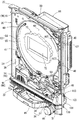
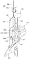
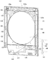
図1は遊技機の外枠の一側に本体枠が開かれその本体枠の一側にガラス扉が開かれた状態を示す斜視図である。図2は遊技機の前側全体を示す正面図である。図3は遊技機の本体枠と遊技盤とを分離して斜め右上前方から示す斜視図である。図4は遊技機の本体枠を斜め右上前方から示す斜視図である。図5は遊技機の本体枠を斜め右上後方から示す斜視図である。図6は施錠装置の下半部を示す斜視図である。図7はガラス扉の閉止具を示す斜視図である。図8は施錠装置の本体枠施錠フック、扉施錠フック及び本体枠の挿通部の関係を示す斜視図である。図9は本体枠の挿通部の正面の孔形状及び扉施錠フックと閉止具の係合状態を示す説明図である。図10は施錠装置の本体枠施錠フック、扉施錠フック及び本体枠の挿通部の関係を示す側断面図である。図11はガラス扉を斜め下後方から示す斜視図である。図12はガラス扉に対し扉拘束体を分離した状態を後方から示す斜視図である。図13は本体枠の扉受け部とガラス扉の扉ガイド体とが分離した状態を示す斜視図である。図14は本体枠に対しガラス扉が閉じられた状態の扉受け部と扉ガイド体との関係を示す側断面図である。図15は本体枠に対しガラス扉が閉じられた状態のヒンジ側を拡大して示す平断面図である。図16は本体枠に対しガラス扉が閉じられた状態の自由端側を拡大して示す平断面図である。なお、説明の便宜上、遊技機において遊技者側を前、反対側を後として説明する。 FIG. 1 is a perspective view showing a state in which a main body frame is opened on one side of an outer frame of the gaming machine and a glass door is opened on one side of the main body frame. FIG. 2 is a front view showing the entire front side of the gaming machine. FIG. 3 is a perspective view showing the main body frame of the gaming machine and the game board separated from each other from the diagonally upper right front. FIG. 4 is a perspective view showing the main body frame of the gaming machine obliquely from the upper right front. FIG. 5 is a perspective view showing the main body frame of the gaming machine obliquely from the upper right rear. FIG. 6 is a perspective view showing the lower half of the locking device. FIG. 7 is a perspective view showing a glass door closing tool. FIG. 8 is a perspective view showing the relationship between the main body frame locking hook, the door locking hook, and the insertion portion of the main body frame of the locking device. FIG. 9 is an explanatory view showing a hole shape in the front of the insertion portion of the main body frame and an engagement state between the door locking hook and the closing tool. FIG. 10 is a side sectional view showing the relationship between the main body frame locking hook, the door locking hook, and the main body frame insertion portion of the locking device. FIG. 11 is a perspective view showing the glass door obliquely from the lower rear. FIG. 12 is a perspective view showing a state in which the door restraint body is separated from the glass door from the rear. FIG. 13 is a perspective view showing a state where the door receiving portion of the main body frame and the door guide body of the glass door are separated. FIG. 14 is a side sectional view showing a relationship between the door receiving portion and the door guide body in a state where the glass door is closed with respect to the main body frame. FIG. 15 is an enlarged plan sectional view showing the hinge side with the glass door closed with respect to the main body frame. FIG. 16 is an enlarged plan view showing a free end side in a state where the glass door is closed with respect to the main body frame. For convenience of explanation, in the gaming machine, the player side will be described as the front and the opposite side as the back.
[遊技機の概要について]
図1と図2に示すように、遊技機としてのパチンコ機は、外枠10、本体枠30、遊技盤61、ガラス扉120等を備えて構成されている。
外枠10は、上下左右の枠材によって縦長四角形の枠状に形成され、同外枠10の前側下部には、本体枠30の下面を受ける下受板15を有している。
外枠10の前面の一側には、本体枠開閉用ヒンジ機構20によって本体枠30が前方に開閉可能に装着されている。
[About the outline of gaming machines]
As shown in FIGS. 1 and 2, a pachinko machine as a gaming machine includes an
The
A
[本体枠について]
図3と図4に示すように、本体枠30は、前枠体31、遊技盤装着枠60及び機構装着体80を合成樹脂材によって一体成形することで構成されている。
本体枠30の前側に形成された前枠体31は、外枠10前側の下受板15を除く外郭形状に対応する大きさの矩形枠状に形成されている。そして、前枠体31の片側の上下部には、外枠10側の外枠側ヒンジ具21に対応する本体枠側ヒンジ具22が固定され、その本体枠側ヒンジ具22において、外枠10の片側の上下部に固定された外枠側ヒンジ具21にヒンジピンとヒンジ孔によって開閉回動可能に装着されている。すなわち、外枠側ヒンジ具21、本体枠側ヒンジ具22、ヒンジピン及びヒンジ孔によって本体枠開閉用ヒンジ機構20が構成されている。
図3と図4に示すように、本体枠30の前枠体31の後部に一体に形成された遊技盤装着枠60は、矩形の遊技盤61が前方から着脱交換可能に装着されるようになっている。
言い換えると、本体枠30の前枠体31は、遊技盤61が装着される開口部を有する遊技盤装着枠60の周囲に張り出すように形成されている。
[About the body frame]
As shown in FIGS. 3 and 4, the
The
As shown in FIGS. 3 and 4, the game
In other words, the
図3と図4に示すように、本体枠30の前枠体31の前側において、遊技盤装着枠60よりも下方に位置する前枠体31の前下部領域の一側寄りには、スピーカ装着板54を介してスピーカ55が装着されている。
また、前枠体31前面の下部領域内には、その上側部分に発射レール装着部が形成され、下側部分には、下皿装着部が発射レール装着部よりも前側に突出して段差状に形成されている。そして、発射レール装着部には、遊技盤61の発射通路に向けて球を導く発射レール50が傾斜状に装着されている。
また、下皿装着部の前側には、その下皿装着部を覆うようにして下前面部材51が装着されている。下前面部材51の前面の略中央部には、下皿45が設けられ、片側寄りには操作ハンドル46が設けられている(図1参照)。
As shown in FIGS. 3 and 4, on the front side of the
Further, in the lower area of the front surface of the
Further, a
[遊技盤について]
図3と図4に示すように、遊技盤61は、遊技盤装着枠60の前方から嵌込まれる大きさの略四角板状に形成されている。
また、遊技盤61の盤面(前面)には、外レール64と内レール65とを備えた案内レール63が設けられ、その案内レール63の内側に遊技領域66が区画形成されている。
遊技盤61には、その遊技領域66内において、遊技に関する役物装置、例えば、センタ役物と呼ばれる役物装置70、図柄表示装置(例えば、液晶表示器、EL表示器,プラズマ表示器,CRT等)72、入賞器、風車器、誘導釘、ランプ装飾部材等の各種の装備品が配設されている。
また、遊技盤61の前面には、その案内レール63の外側領域において、合成樹脂製の前構成部材61aが装着されている。
[About the game board]
As shown in FIGS. 3 and 4, the
Further, a
In the
Further, a front
また、図3に示すように、遊技盤61前面の前構成部材61aの他側寄りの上下2箇所には、ロック部材62がピンと左右方向の長孔によって回動操作可能に装着されている。
そして、遊技盤61(前構成部材61aを含む)は、その左側部が遊技盤装着枠60の後面受け部と前面押え部との間に差し込まれ、ロック部材62の先端部が遊技盤装着枠60の係止部に係合されることで装着されるようになっている(図1参照)。
なお、遊技盤61の後側には、遊技の進行を制御する主制御基板や周辺機器(ランプ、スピーカ等)を制御する副制御基板が配置されている。
また、図5に示すように、本体枠30の後側に一体に形成された機構装着体80には、球タンク81、タンクレール82、球払出装置83等が配設されている。
Further, as shown in FIG. 3,
The game board 61 (including the
A main control board for controlling the progress of the game and a sub control board for controlling peripheral devices (lamps, speakers, etc.) are arranged on the rear side of the
Further, as shown in FIG. 5, a
[施錠装置について]
図5〜図10に示すように、本体枠(前枠体31)30のヒンジ機構と反対側に自由端側の後側には、外枠10に対し本体枠30を施錠する機能と、本体枠30に対し後に詳述するガラス扉120を施錠する機能とを兼ね備えた施錠装置100が装着されている。
すなわち、この実施例において、施錠装置100は、本体枠30の前枠体31の自由端側の後側に固定状態で装着された上下方向に長尺な取付基板101に対し、本体枠施錠部材102、扉施錠部材106、シリンダー錠110等が組み付けられて構成されている。
本体枠施錠部材102は、上下の施錠板102aが連結体104によって一体状に連結されることで形成されるとともに、取付基板101に対し上下方向に移動可能に組み付けられかつばね(図示しない)によってロック方向(上方)に付勢されている。
そして、本体枠施錠部材102の上下の施錠板102aには、外枠10に設けられた閉止具17に係脱可能に係合して本体枠30を閉じ状態に施錠する本体枠施錠フック103が後方に向けて突出されている(図5参照)。なお、本体枠施錠部材102を長尺部材によって一体に形成し、その上下部に本体枠施錠フック103を形成しても実施可能である。
[About locking device]
As shown in FIGS. 5 to 10, a function of locking the
That is, in this embodiment, the
The main body
The upper and
扉施錠部材106は長尺状に形成されて取付基板101に対し上下方向に移動可能に組み付けられかつばね(図示しない)によってロック方向(下方)に付勢されている(図5及び図6参照)。
扉施錠部材106には、ガラス扉120の各閉止具130に対応する複数(この実施例では上下及び中間の計3つ)の扉施錠フック107が前方に向けて突出されている(図4参照)。
図8〜図10に示すように、各扉施錠フック107は、本体枠(前枠体31)30の自由端寄り部分に貫設された角孔状の挿通部40に挿通されてガラス扉120の閉止具130に係脱可能に臨んでいる。そして、各扉施錠フック107の前端下部には、傾斜状の案内面108と上下方向に延びる係止面109とを備えて略三角形状をなす係止部107aが係止されている。
The
On the
As shown in FIGS. 8 to 10, each
また、図8〜図10に示すように、本体枠(前枠体31)30の挿通部40は、施錠装置100の扉施錠フック107、閉止具130の側壁片132及び横方向の係合片133が挿通される縦長の孔状に形成されている。そして、ガラス扉120が閉じ位置まで閉じられたときに、そのガラス扉120の閉止具130の側壁片132及び係合片133が挿通部40内に進入して扉施錠フック107に係脱可能に係合するようになっている。
さらに、図8と図9に示すように、挿通部40には、その縦方向の略中央部に位置しかつ閉止具130の横方向の係合片133の挿通を許容する幅広の係合片挿通部40aが設けられている。
しかも、扉施錠フック107前端の係止部107aが本体枠30の挿通部40から前方に突出することがない程度に挿通部40の前後方向の寸法が設定されている。
なお、閉止具130については後に詳述する。
As shown in FIGS. 8 to 10, the
Further, as shown in FIGS. 8 and 9, the
Moreover, the dimension in the front-rear direction of the
The
また、図5と図6に示すように、取付基板101の所定位置には、シリンダー錠110が装着され、そのシリンダー錠110の前端部は、図2と図3に示すように、遊技機の前方から鍵を挿入されて解錠操作可能に、前枠体31及び下前面部材51を貫通してその下前面部材51の前面に露出されている。
図6に示すように、シリンダー錠110の錠軸111の後端部には解錠体112が一体状に設けられており、その解錠体112には、本体枠施錠部材102の下側の施錠板102aに切り欠き状に形成された係合部102bに係合可能な第1解錠片113と、扉施錠部材106の下端縁に形成された係合部106aに係合可能な第2解錠片114とがそれぞれ形成されている。
そして、シリンダー錠110の鍵穴に鍵が挿入されて一方向に回動操作され、解錠体112が図6に向かって反時計回り方向に回動されることで、その第1解錠片113が下側の施錠板102aの係合部102bに係合しながら本体枠施錠部材102が押し下げられ、これによって本体枠施錠フック103と外枠10の閉止具17との係合が外れて本体枠30が解錠される。これとは逆方向に回動操作され、解錠体112が図6に向かって時計回り方向に回動されることで、第2解錠片114が扉施錠部材106の係合部106aに係合しながら扉施錠部材106が押し上げられ、これによって扉施錠フック107とガラス扉120の閉止具130との係合が外れてガラス扉120が解錠されるようになっている。
Further, as shown in FIGS. 5 and 6, a
As shown in FIG. 6, an unlocking
Then, a key is inserted into the key hole of the
[本体枠の扉用拘束部及び扉受け部について]
図4と図15に示すように、この実施例において、本体枠(前枠体31)30のヒンジ側の枠部内側の上下方向の中間高さ位置から下側寄り部分には、後述するガラス扉120の後面の扉拘束体140に係合することで、ガラス扉120が前方に向けて不測にこじ開けられることを防止するための扉用拘束部39が内方に向けて突設されている。なお、扉用拘束部39は、ガラス扉120の不測のこじ開けを防止できる程度の係合力を確保できる長さ寸法(上下方向の寸法)に設定され、後述する扉拘束体140よりも短尺に形成されている。
また、図4、図13及び図14に示すように、本体枠(前枠体31)30の前側の下部領域の段差部の自由端側寄り部分(左右方向中央部からヒンジ寄りに位置する部分)には、ガラス扉120の下端部を受ける扉受け部34が形成されている。
この扉受け部34は、前側が低く後側が高い傾斜面37上に前後方向に延びる複数又は単数の扉受け用突部38が突設されることで構成されている。そして、各扉受け用突部38の前側上端部には傾斜面、円弧面、湾曲面等の面取り状の案内部38aが形成されている。
[Restraining part for door and door receiving part of main frame]
As shown in FIG. 4 and FIG. 15, in this embodiment, a glass, which will be described later, is disposed on the lower side portion from the middle height position in the vertical direction inside the frame portion on the hinge side of the main body frame (front frame body 31) 30. By engaging with the
Also, as shown in FIGS. 4, 13, and 14, the portion near the free end of the step portion of the lower region on the front side of the main body frame (front frame body 31) (the portion located closer to the hinge from the central portion in the left-right direction) ) Is formed with a
The
[ガラス扉について]
図4に示すように、本体枠(前枠体31)30の前面の一側上下部には、扉開閉用ヒンジ機構90を構成する扉用ヒンジ具91が装着されている。そして、図1に示すように、本体枠(前枠体31)30前面の一側には、扉開閉用ヒンジ機構90によってガラス扉120が前方に開閉可能に装着されている。
図1、図2、図11及び図12に示すように、ガラス扉120は、金属製の扉フレーム120aと、合成樹脂製の単数又は複数の前面装飾部材124とを主体として構成されている。
ガラス扉120の扉フレーム120aは、鉄板等の金属板がプレス加工によって所要とする形状に形成されている。
この実施例において、図1、図11及び図12に示すように、扉フレーム120aは、本体枠30の前枠体31の上端から下部前面板51の上縁にわたる部分を覆う大きさに形成され、その略中央部には、遊技盤61の遊技領域66を前方から透視可能な略円形の開口窓121が形成されている。また、扉フレーム120aの後側には、開口窓121よりも大きいかつ底壁と左右の両側壁を備えて矩形状をなす金属製の窓枠122が溶接によって一体状に固着され、その窓枠122にはガラス板、透明樹脂板等の透明板123が着脱交換可能に装着されている。また、窓枠122の左右の両側壁の上端部に跨ってガラス押え体122aが開閉可能あるいは着脱可能に装着されている。
[About glass doors]
As shown in FIG. 4, a
As shown in FIGS. 1, 2, 11, and 12, the
The
In this embodiment, as shown in FIGS. 1, 11, and 12, the
図2に示すように、ガラス扉120の扉フレーム120aの前面には、その開口窓121の周囲の下側部分を除く略全体にわたって、ランプ等が内設された合成樹脂製の前面装飾部材124が装着されており、同ガラス扉120の扉フレーム120aの前面の下部には上皿部材125が設けられている。
また、図11と図12に示すように、ガラス扉120の後側には、その窓枠122よりも下方でかつヒンジ寄り部分において、球を上皿部材125に導く上皿用球案内筒126が突設されている。そして、ガラス扉120が閉じられた状態において、上皿用球案内筒126の後端部が球払出装置の払出口に連通状に配置されるようになっている。
As shown in FIG. 2, the front
Further, as shown in FIGS. 11 and 12, on the rear side of the
[ガラス扉の閉止具について]
図7〜図12に示すように、ガラス扉120の扉開閉用ヒンジ機構90と反対側の自由端側において、同ガラス扉120の後側には、施錠装置100の各扉施錠フック107に係脱可能に係合してガラス扉120を閉じ状態に施錠する複数(この実施例では上下及び中間の計3つ)の金属製の閉止具130が設けられている。
[About glass door closures]
As shown in FIGS. 7 to 12, on the free end side of the
図7〜図10に示すように、各閉止具130は、ガラス扉120の後面に沿ってビス、溶接等によって固着された取付片131とその取付片131の外端から後方に向けて略直角状に折り曲げられ突出された側壁片132と、その側壁片132の後端から内側に向けて略直角状に折り返されることで本体枠30の前面に平行して横方向に延び、かつ扉施錠フック107に係脱可能な係合片133とを一体に備えている。
そして、図9と図10に示すように、本体枠30に対し扉開閉用ヒンジ機構90を支点としてガラス扉120が閉じ位置まで閉じられたときには、そのガラス扉120の各閉止具130の側壁片132及び係合片133が本体枠30の挿通部40内に進入しかつ係合片133が扉施錠フック107の係止部170aの係止面109に係脱可能に係合するようになっている。
As shown in FIGS. 7 to 10, each closing
9 and 10, when the
また、図9に示すように、閉止具130の係合片133が扉施錠フック107の係止部107aの係止面109に係合してガラス扉120が閉じ位置に施錠された状態において、扉施錠フック107の係止部107aと閉止具130の係合片133との係合部分は閉止具130の側壁片132によって覆い隠されるようになっている。
また、ガラス扉120の金属製の扉フレーム120aの後面に対し、閉止具130をその取付片131においてビス、溶接等によって固着する際に、ビス締め工具、あるいは溶接ガンが閉止具130の係合片133に当たって干渉することがないように閉止具130の取付片131と係合片133とが上下方向に相互に位置ずれして設けられている。この実施例では、閉止具130の上下部に取付片131が形成され、中間部に係合片133が形成されている。
Further, as shown in FIG. 9, in the state where the
Further, when the
また、この実施例において、図16に示すように、ガラス扉120の周縁部と、これに対向する本体枠30の枠体部分のうち、少なくともガラス扉120の自由端縁と、これに対向する本体枠30の枠体部分には、ガラス扉120が閉じられたときに相互に嵌合する上下方向に長尺の嵌合凹部150と嵌合凸部155とがそれぞれ設けられている。
この実施例において、本体枠30の枠体部分の前面には、その上端部から下端部にわたって、外側に浅底部151、内側に深底部152を隣接状に有する段差状の嵌合凹部150が凹設されている。
一方、ガラス扉120の自由端縁には、段差状の嵌合凹部150に対応する第1凸部156と第2凸部157とを隣接状に有する段差状の嵌合凸部155が、ガラス扉120の上端部から下端部にわたって凸設されている。
すなわち、この実施例において、ガラス扉120の合成樹脂製の前面装飾部材124の自由端縁には、その嵌合凹部150の浅底部151に嵌込まれる第1凸部156が一体に形成され、金属製の扉フレーム120aの自由端縁には、嵌合凹部150の深底部152に嵌込まれる第2凸部157が折り曲げ加工によって一体に形成されている。
なお、嵌合凹部150と嵌合凸部155は、ガラス扉120の全周縁部と、これに対向する本体枠30の四辺の枠体部分にそれぞれ設けることも可能である。なお、嵌合凹部150と嵌合凸部155は段差状でなくてもよい。
Further, in this embodiment, as shown in FIG. 16, at least the free edge of the
In this embodiment, a step-like
On the other hand, at the free edge of the
That is, in this embodiment, the first
Note that the
[扉拘束体について]
図11、図12及び図15に示すように、ガラス扉120の後面のヒンジ側には、その上下方向の中間高さ位置近傍から下部近傍にわたる長さを有して上下方向に長尺に形成された金属製の扉拘束体140が装着されている。
この扉拘束体140は、金属板の折り曲げ加工によって横断面略コの字状に形成され、ガラス扉120の金属製の扉フレーム120aの後面に沿ってビス、溶接等によって固着された取付片141と、その取付片141の内端から後方に向けて略直角状に折り曲げられた側壁片142と、その側壁片142の後端から外側に向けて略直角状に折り返されかつ本体枠(前枠体31)30の扉用拘束部39に係脱可能な係合片143とを一体に備えている。
そして、図15に示すように、本体枠30に対し扉開閉用ヒンジ機構90を支点としてガラス扉120が閉じ位置まで閉じられたときには、扉拘束体140の係合片143が本体枠(前枠体31)30の扉用拘束部39の後側に接近して係合可能に配置され、これによってガラス扉120が前方に向けて不測にこじ開けられて不正行為がなされることを防止するようになっている。
また、ガラス扉120の金属製の扉フレーム120aの後面に対し、扉拘束体140をその取付片141においてビス、溶接等によって固着する際に、ビス締め工具、あるいは溶接ガンが扉拘束体140の係合片143に当たって干渉することがないように扉拘束体140の取付片141の横断面の長さ寸法が、係合片143の横断面の長さ寸法よりも大きく設定されている。
[About door restraints]
As shown in FIGS. 11, 12, and 15, on the hinge side of the rear surface of the
The
As shown in FIG. 15, when the
Further, when the
[扉ガイド体について]
図11、図12、図13及び図14に示すように、ガラス扉120の後側の自由端寄り下部には、本体枠(前枠体31)30前側の扉受け部34に対応する位置において、扉ガイド体127が後方に向けて突設されている。
この扉ガイド体127の後端部下面には、扉受け部34の扉受け用突部38上を滑走してガラス扉120を閉じ案内するための傾斜状、円弧状、湾曲状等の面取り状のガイド面128が形成されている。
そして、図14に示すように、本体枠30に対し扉開閉用ヒンジ機構90を支点としてガラス扉120が閉じ位置まで閉じられたときには、扉ガイド体127が扉受け部34の扉受け用突部38上を滑走してガラス扉120を閉じ案内するとともに、ガラス扉120の自由端側が下傾することなく正規の閉じ状態に保持するようになっている。
[About the door guide body]
As shown in FIGS. 11, 12, 13, and 14, the lower portion of the
On the lower surface of the rear end portion of the
As shown in FIG. 14, when the
[実施例に係る遊技機の作用効果について]
上述したように構成されるこの実施例に係る遊技機において、図8〜図10に示すように、本体枠30に対し扉開閉用ヒンジ機構90を支点としてガラス扉120が閉じ位置まで閉じられたときには、そのガラス扉120の閉止具130の側壁片132及び係合片133が本体枠30の挿通部40内に進入しかつ係合片133が扉施錠フック107の係止部170aの係止面109に係脱可能に係合する。これによって、本体枠30に対しガラス扉120が閉じ位置で施錠される。
[About the effects of the gaming machine according to the embodiment]
In the gaming machine according to this embodiment configured as described above, the
このようにして、本体枠30の挿通部40内において扉施錠フック107と閉止具130とを係脱可能に係合させる配置スペースを確保することができる。
このため、扉施錠フックと閉止具とを係脱可能に係合させる配置スペースをガラス扉120側に確保する必要がない。これによって、ガラス扉120の設計の自由度を高めることができる。
言い換えると、扉施錠フックと閉止具とを係脱可能に係合させる配置スペースをガラス扉120側に確保すると、これによってガラス扉120の設計の自由度が制限されるが、この実施例においては、本体枠30の挿通部40内において扉施錠フック107と閉止具130とを係脱可能に係合させる配置スペースを確保することで、ガラス扉120の設計の自由度を高めることができる。例えば、ガラス扉120の奥行き寸法が小さく制限される場合において効果が大きい。
In this way, it is possible to secure an arrangement space for detachably engaging the
For this reason, it is not necessary to ensure the arrangement | positioning space which engages a door locking hook and a closing tool so that engagement / disengagement is possible on the
In other words, if the arrangement space for detachably engaging the door locking hook and the closing tool is secured on the
また、この実施例において、ガラス扉120の自由端部に対向する前枠体31の枠体部分の後面に、施錠装置100が配設され、その枠体部分に扉施錠フック107に対応する挿通部40が形成される。
すなわち、遊技盤装着枠60の外側において、施錠装置100及びその扉施錠フック107が配置されるため、遊技盤装着枠60に対し遊技盤61を着脱する際に、施錠装置100や扉施錠フック107が妨害物となることを防止することができ、遊技盤装着枠60に対し遊技盤61を容易に着脱することができる。さらに、遊技盤装着枠60に遊技盤61が装着された状態において、遊技盤61やその遊技盤61に装着される装備品に干渉することなく施錠装置100や扉施錠フック107を配置することができる。
In this embodiment, the
That is, since the
また、この実施例において、本体枠30は、前枠体31、遊技盤装着枠60及び同遊技盤装着枠60の後側に配置されかつ球タンク81、タンクレール82、球払出装置83等が装着される機構装着体80を一体に備えるととともに、合成樹脂材によって一体成形されている。
前記したように、前枠体31、遊技盤装着枠60及び機構装着体80を備えて合成樹脂材によって一体成形される本体枠30は、奥行き寸法が大きくなる。これによって、前枠体31の後面でかつガラス扉120の自由端部に対向する枠体部分の後方には、奥行き寸法の大きいスペースが生まれる。そして、枠体部分の後方の奥行き寸法の大きいスペースを有効利用して、そのスペース内に施錠装置100を配設することができる。
In this embodiment, the
As described above, the
また、この実施例において、図7に示すように、金属製の閉止具130は、その取付片131において、ガラス扉120の金属製の扉フレーム120a後面にビス、溶接等によって安定よく強固に固着される。
また、本体枠30に対しガラス扉120が閉じられた状態において、閉止具130の側壁片132及び係合片133が本体枠30の挿通部40内に進入しかつその係合片133が扉施錠フック107の係止部107aに係脱可能に係合する。
このようにして、閉止具130の側壁片132及び係合片133を本体枠30の挿通部40内に進入させ、かつ本体枠30の挿通部40内において、閉止具130の係合片133を扉施錠フック107の係止部107aに確実に係合させることができる。
Further, in this embodiment, as shown in FIG. 7, the
When the
In this way, the
また、この実施例において、本体枠30の挿通部40は、施錠装置100の扉施錠フック107及び閉止具130の側壁片132が挿通される縦長の孔状に形成され、挿通部40の略中央部には、閉止具130の横方向の係合片133の挿通を許容する幅広の係合片挿通部40aが設けられている。
このため、縦長の孔状の挿通部40には、施錠装置100の扉施錠フック107及び閉止具130の側壁片132が良好に挿通される。さらに、挿通部40の幅広の係合片挿通部40aには閉止具130の横方向に延びる係合片133が良好に挿通される。
すなわち、縦長の孔状に形成された挿通部を、その縦方向全長にわたり、横方向に延びる係合片133に対応して幅広に形成すると、本体枠30の強度が、その幅広の挿通部が形成される部分において著しく低下する。これによって、幅広の挿通部の近傍に亀裂や破損が発生し易くなるが、前記したように、縦長の孔状をなす挿通部40において、閉止具130の横方向に延びる係合片133に対応する部分においてのみ、幅広の係合片挿通部40aを設けることで、本体枠30の強度低下を良好に抑えることができる。
Further, in this embodiment, the
For this reason, the
That is, when the insertion portion formed in the shape of a vertically long hole is formed wide corresponding to the
また、この実施例において、図9に示すように、本体枠30側の扉施錠フック107の係止部107aと、ガラス扉120側の閉止具130の係合片133との係合部分が同閉止具130の側壁片132によって覆い隠されるため、仮に、本体枠30とガラス扉120との間の隙間から線材、板材等の異物が侵入され、その異物が扉施錠フック107の係止部107aと閉止具130の係合片133との係合部分に向けて侵入することを閉止具130の側壁片132によって阻止することができる。このため、本体枠30とガラス扉120との間の隙間から線材、板材等の異物が侵入され、その異物によって扉施錠フック107の係止部107aと閉止具130の係合片133との係合が外され、ガラス扉120が不正に開かれることを防止することができる。
Further, in this embodiment, as shown in FIG. 9, the engaging portions of the locking
また、この実施例において、扉施錠フック107の前端部、すなわち係合部107aが本体枠30の挿通部40から前方に突出することがない程度に挿通部40の前後方向の寸法が設定されている。このため、本体枠30の挿通部40内において扉施錠フック107と閉止具130とを係脱可能に係合させる配置スペースを充分に確保することができ、扉施錠フック107の係合部107aに対応するスペースにおいてもガラス扉120側に確保する必要がない。この結果、ガラス扉120の設計の自由度を増大させることができる。
Further, in this embodiment, the front and rear dimensions of the
また、この実施例において、図14に示すように、本体枠30に対し扉開閉用ヒンジ機構90を支点としてガラス扉120が閉じ位置まで閉じられるときには、扉ガイド体127の後端部下面の面取り状のガイド面128が、扉受け部34の扉受け用突部38の前側上端部の面取り状の案内部38aに接して滑走した後、扉受け用突部38上を滑走してガラス扉120を閉じ案内することができる。そして、ガラス扉120が閉じ位置まで閉じられたときには、扉ガイド体127の下面が扉受け部34の扉受け用突部38によって受け支えられる。
これによって、ガラス扉120の自由端側が不測に下傾することなく正規の閉じ状態に保持することができ、かつ施錠装置100の扉施錠フック107と閉止具130とを係合不良なく確実に係合させることができる。
In this embodiment, as shown in FIG. 14, when the
As a result, the free end side of the
特に、この実施例において、ガラス扉120は、その下部に上皿部材125が一体状に設けられた大型のガラス扉120であり、上皿部材125が設けられない形式のガラス扉と比べその重量も重い。
このように大型で重量が重いガラス扉120であっても、扉ガイド体127の自由端寄り部分の下面を扉受け部34によって受け支えることで、ガラス扉120の自由端側が不測に下傾する不具合を防止することができる。
また、この実施例において、図13と図14に示すように、扉受け用突部38の前側上端部には傾斜面、円弧面、湾曲面等の面取り状の案内部38aが形成され、扉ガイド体127の後端部下面には、傾斜状、円弧状、湾曲状等の面取り状のガイド面128が形成されている。
これによって、本体枠30に対し扉開閉用ヒンジ機構90を支点としてガラス扉120が閉じ位置まで閉じられる際に、扉受け用突部38の案内部38aに沿って扉ガイド体127のガイド面128が円滑に接しながら滑走するため、扉受け用突部38に扉ガイド体127が衝突して相互に損傷される不具合を解消することができる。
In particular, in this embodiment, the
Even in such a large and
Further, in this embodiment, as shown in FIGS. 13 and 14, a
Thus, when the
また、この実施例において、図16に示すように、ガラス扉120の周縁部とこれに対向する本体枠30の枠体部分のうち、少なくとも前記ガラス扉120の自由端縁と、これに対向する本体枠30の枠体部分には、ガラス扉120が閉じられたときに相互に嵌合する上下方向に長尺の嵌合凹部150と嵌合凸部155とがそれぞれ設けられている。そして、ガラス扉120が閉じられた状態にあるときには、上下方向に長尺の嵌合凹部150と嵌合凸部155と嵌合によって、ガラス扉120の自由端縁と、これに対向する本体枠30の枠体部分との間の隙間が塞がれる。
このようにして、ガラス扉120の自由端縁と、これに対向する本体枠30の枠体部分との間の隙間が塞がれることで、本体枠30とガラス扉120との間に、線材、板材等の異物が侵入されることを防止することができる。このため、本体枠30とガラス扉120との間の隙間から侵入される線材、板材等の異物によって扉施錠フック107と閉止具130との係合が外され、ガラス扉120が不正に開かれることを防止することができる。
Further, in this embodiment, as shown in FIG. 16, at least the free edge of the
In this manner, the gap between the free edge of the
また、この実施例において、本体枠30の枠体部分の前面の嵌合凹部150は、外側に浅底部151、内側に深底部152を隣接状に有する段差状に形成される一方、ガラス扉120の自由端縁の嵌合凸部155は、段差状の嵌合凹部150に対応する第1凸部156と第2凸部157とを隣接状に有している。
さらに、ガラス扉120の合成樹脂製の前面装飾部材124の自由端縁に、第1凸部156が一体に形成され、ガラス扉120の金属製の扉フレーム120aの自由端縁に第2凸部157が折り曲げ加工によって一体に形成されている。
このため、仮に、合成樹脂製の本体枠30の嵌合凹部150の外側壁153やガラス扉120の合成樹脂製の前面装飾部材124の第1凸部156が、加熱された金属棒やタバコの火等によって部分的に溶融されて孔が明けられ、その孔から異物が不測に侵入されたとしても、その異物を金属製の扉フレーム120aに第2凸部157によってこれ以上奥まで侵入されることを防止することができる。
Further, in this embodiment, the
Furthermore, the first
For this reason, temporarily, the
また、この実施例において、図15に示すように、本体枠30に対し扉開閉用ヒンジ機構90を支点としてガラス扉120が閉じ位置まで閉じられたときには、ガラス扉120の扉拘束体140の係合片143が本体枠(前枠体31)30の扉用拘束部39の後側に接近して係合可能に配置される。
これによって、本体枠30とガラス扉120との間のヒンジ側において、ワイヤ、ドライバー等の異物が挿入されてガラス扉120が前方に向けて不測にこじ開けられて不正行為がなされることを防止することができる。
しかも、金属製の扉拘束体140は、ガラス扉120の上下方向の略中間高さ位置近傍から下端部近傍にわたる長さを有して上下方向に長尺に形成されるとともに、遊技盤61の上下方向の略中間高さ位置から下端にわたる長さを有している。
このため、遊技盤61の上下方向の略中間高さ位置から下端との間に配置される入賞役物(入賞装置)、例えば、大入賞口を開閉可能に有するアタッカとも呼ばれている可変入賞役物(図示しない)に対する不正行為の防止に効果が大きい。
すなわち、アタッカ(可変入賞役物)をねらって、そのアタッカの側方における本体枠30とガラス扉120との間のヒンジ側の隙間に対し、ワイヤ、ドライバー等の異物が侵入されたとしても、上下方向に長尺の金属製の扉拘束体140によって異物の侵入を阻止することができ、アタッカ(可変入賞役物)に対する不正行為の防止に効果が大きい。さらに、ワイヤ、ドライバー等の異物が加熱されている場合においても、金属製の扉拘束体140によって異物の侵入を阻止することができる。
Further, in this embodiment, as shown in FIG. 15, when the
As a result, foreign matter such as a wire or a screwdriver is inserted on the hinge side between the
In addition, the metal
For this reason, a winning combination (winning device), for example, an attacker having a large winning opening that can be opened and closed, is arranged between a substantially intermediate height position in the vertical direction of the
That is, even if a foreign object such as a wire or a driver enters the gap on the hinge side between the
また、ガラス扉120の金属製の扉フレーム120aの後面に対し、扉拘束体140をその取付片141においてビス、溶接等によって固着する際に、ビス締め工具、あるいは溶接ガンが扉拘束体140の係合片143に当たって干渉することがないように扉拘束体140の取付片141の横断面の長さ寸法が、係合片143の横断面の長さ寸法よりも大きく設定されている。
このため、ガラス扉120の金属製の扉フレーム120aの後面に対し、扉拘束体140をその取付片141においてビス、溶接等によって固着する際に、係合片143が妨害物とならないため、金属製の扉フレーム120aの後面に対し、扉拘束体140をその取付片141においてビス、溶接等によって容易にかつ強固に固着することができる。
Further, when the
For this reason, since the
[この発明の他の実施例について]
なお、この発明は実施例に限定するものではない。
例えば、実施例においては、前枠体31、遊技盤装着枠60及び機構装着体80が合成樹脂材によって一体成形されることで本体枠30が構成される場合を例示したが、遊技盤が着脱可能に装着される遊技盤装着枠が一体に形成されたりあるいは別体の遊技盤装着枠が組み付けられる前枠体が本体枠である場合おいてもこの発明を実施することができる。。また、前枠体は合成樹脂材以外の木質製であってもよい。
また、ガラス扉120の閉止具130及び扉施錠フック107に対応して本体枠30の自由端部に形成された挿通部40においては、貫通孔状であってもよく、また切り欠き状であってもよい。
[Other Embodiments of the Invention]
In addition, this invention is not limited to an Example.
For example, in the embodiment, the case where the
Further, the
前記実施例は次に述べる他の発明を含んでいる。 The embodiment includes other inventions described below.
[他の発明の手段及び作用効果について]
他の発明1の手段1は、
「(請求項1)本体枠の前面の一側部には、扉開閉用ヒンジ機構によってガラス扉が開閉可能に装着され、前記本体枠の後面の他側部には、前記ガラス扉を閉じ状態に施錠する施錠装置が配設された遊技機であって、
前記本体枠と前記ガラス扉のヒンジ側には、同ガラス扉が閉じられたときに係脱可能に係合してガラス扉がこじ開けられることを阻止する扉拘束手段が設けられ、
前記扉拘束手段は、前記本体枠に設けられた扉拘束部と、前記ガラス扉の後面に設けられかつ前記扉拘束部に係脱可能に係合する扉拘束体と、を備え、
前記扉拘束体は、上下方向に長尺状に形成されるていることを特徴とする遊技機。」を要旨とする。
ここで、本体枠は、外枠に開閉可能に装着された前枠体、あるいは前枠体と遊技盤装着枠とを一体に備えたもの、あるいは前枠体、遊技盤装着枠及び機構装着体を一体に備えたものも含む。
[Means and effects of other inventions]
The means 1 of the other invention 1 is as follows:
“(Claim 1) A glass door is mounted on one side of the front surface of the main body frame by a door opening / closing hinge mechanism, and the glass door is closed on the other side of the rear surface of the main body frame. A gaming machine provided with a locking device for locking the
On the hinge side of the main body frame and the glass door, a door restraining means is provided for preventing the glass door from being pry open by detachably engaging when the glass door is closed,
The door restraining means includes a door restraining portion provided on the main body frame, and a door restraining body provided on a rear surface of the glass door and detachably engaged with the door restraining portion,
The gaming machine, wherein the door restraint body is formed in an elongated shape in the vertical direction. Is the gist.
Here, the main body frame is a front frame body that is attached to the outer frame so as to be openable and closable, or a body that integrally includes the front frame body and the game board mounting frame, or the front frame body, the game board mounting frame, and the mechanism mounting body. Including those that are integrated.
前記構成において、本体枠とガラス扉との間のヒンジ側において、ワイヤ、ドライバー等の異物が挿入されてガラス扉が前方に向けて不測にこじ開けられることを防止することができる。
特に、扉拘束体は、上下方向に長尺状に形成されるため、ワイヤ、ドライバー等の異物の挿入防止やガラス扉のこじ開け防止に効果が大きい。
例えば、本体枠に設けられた遊技盤装着枠に遊技盤が装着された遊技機において、扉拘束体が、遊技盤の上下方向の略中間高さ位置から下端にわたって上下方向に長尺に形成された場合には、遊技盤の上下方向の略中間高さ位置から下端との間に配置される入賞役物(入賞装置)、例えば、大入賞口を開閉可能に有するアタッカとも呼ばれている可変入賞役物(図示しない)に対する不正行為の防止に効果が大きい。
The said structure WHEREIN: On the hinge side between a main body frame and a glass door, foreign materials, such as a wire and a driver, are inserted, and it can prevent that a glass door is opened unexpectedly toward the front.
In particular, since the door restraint body is formed in an elongated shape in the vertical direction, it is highly effective in preventing the insertion of foreign matters such as wires and drivers and the opening of the glass door.
For example, in a gaming machine in which a game board is mounted on a game board mounting frame provided on the main body frame, the door restraint body is formed in a vertically long shape from a substantially middle height position in the vertical direction of the game board to the lower end. In such a case, a winning combination (winning device), for example, an attacker having a large winning opening that can be opened and closed, is arranged between a substantially middle height position in the vertical direction of the game board and the lower end. Greatly effective in preventing fraudulent acts against prize-winning objects (not shown).
他の発明1の手段2は、
「(請求項2)請求項1に記載の遊技機であって、
本体枠は、合成樹脂材によって形成され、
扉拘束部は、前記本体枠を合成樹脂材によって形成すると同時に、同本体枠と一体に形成されていることを特徴とする遊技機。」を要旨とする。
The means 2 of the other invention 1 is as follows:
“(Claim 2) The gaming machine according to claim 1,
The body frame is formed of a synthetic resin material,
The door restraining portion is formed of the synthetic resin material at the same time as the main body frame, and is formed integrally with the main body frame. Is the gist.
前記構成において、本体枠を合成樹脂材によって形成すると同時に、同本体枠と一体に扉拘束部を形成することで、本体枠とは別個に扉拘束部を形成して本体枠に組み付ける手間を省くことができ、部品点数や組付工数を削減してコスト低減を図ることができる。 In the above configuration, the main body frame is formed of a synthetic resin material, and at the same time, the door restraining portion is formed integrally with the main body frame, thereby eliminating the trouble of forming the door restraining portion separately from the main body frame and assembling the main body frame. It is possible to reduce costs by reducing the number of parts and the number of assembly steps.
他の発明1の手段3は、
「(請求項3)請求項1又は2に記載の遊技機であって、
ガラス扉はその後側に金属製の扉フレームを有し、
扉拘束体は、金属板の曲げ加工によって上下方向に長尺状に形成されるとともに、前記ガラス扉の金属製の扉フレームの後面にビス、溶接等によって固着される取付片と、その取付片から後方に向けて突出された側壁片と、その側壁片の先端に設けられかつ本体枠の扉拘束部に係脱可能に係合する係合片と、を一体に備えていることを特徴とする遊技機。」を要旨とする。
The means 3 of the other invention 1 is as follows:
“(Claim 3) The gaming machine according to claim 1 or 2,
The glass door has a metal door frame on its rear side,
The door restraint body is formed in a vertically long shape by bending a metal plate, and is attached to the rear surface of the metal door frame of the glass door by screws, welding, and the like, and the mounting piece A side wall piece projecting rearward from the side wall, and an engagement piece provided at the front end of the side wall piece and detachably engaged with the door restraining portion of the main body frame. To play. Is the gist.
前記構成において、金属板の曲げ加工によって取付片、側壁片及び係合片を備えた扉拘束体を容易に形成することができるとともに、金属製の扉フレームの後面に対し、金属製の扉拘束体をビス、溶接等によって安定よく強固に固着することができる。 In the above configuration, the door restraint body including the attachment piece, the side wall piece, and the engagement piece can be easily formed by bending the metal plate, and the metal door restraint is performed on the rear surface of the metal door frame. The body can be firmly and firmly fixed by screws, welding or the like.
他の発明1の手段4は、
「(請求項4)請求項3に記載の遊技機であって、
ガラス扉の金属製の扉フレームの後面に対し、扉拘束体をその取付片においてビス、溶接等によって固着する際に、前記扉拘束体の係合片が妨害物とならないように、前記扉拘束体の取付片の横断面の長さ寸法が、前記係合片の横断面の長さ寸法よりも大きく設定されていることを特徴とする遊技機。」を要旨とする。
The means 4 of the other invention 1 is as follows:
“(Claim 4) The gaming machine according to claim 3,
When the door restraint body is fixed to the rear surface of the metal door frame of the glass door by screws, welding, or the like, the door restraint body does not interfere with the engagement piece of the door restraint body. A gaming machine characterized in that a length dimension of a cross section of a body attachment piece is set larger than a length dimension of a cross section of the engagement piece. Is the gist.
前記構成において、金属製の扉フレームの後面に対し、扉拘束体をその取付片においてビス、溶接等によって固着する際に、係合片が妨害物とならないため、金属製の扉フレームの後面に対し、扉拘束体をその取付片においてビス、溶接等によって容易に固着することができる。 In the above configuration, when the door restraint body is fixed to the rear surface of the metal door frame by screws, welding, etc., the engagement piece does not become an obstruction, so the rear surface of the metal door frame On the other hand, the door restraint body can be easily fixed to the mounting piece by screws, welding or the like.
遊技機としては、前側にガラス扉のような開閉扉が開閉可能に装着された遊技機であればこの発明を実施可能である。例えば、パチンコ機の他、メダルを用いてスロット遊技を行うスロットマシン、あるいは、球(パチンコ球)を用いてスロット遊技を行う遊技機でる場合においてもこの発明を実施可能である。 As the gaming machine, the present invention can be implemented as long as the opening / closing door such as a glass door is detachably mounted on the front side. For example, in addition to pachinko machines, the present invention can be implemented in the case of slot machines that perform slot games using medals or game machines that perform slot games using balls (pachinko balls).
他の発明2の手段1は、
「(請求項1)
本体枠の前面の一側部に扉開閉用ヒンジ機構によってガラス扉が開閉可能に装着された遊技機であって、
前記ガラス扉の後側の中央部から自由端寄り部分には、同ガラス扉が閉じられたときに、前記本体枠の前側の扉受け部に受け支えられる扉ガイド体が後方に向けて突設されていることを特徴とする遊技機。」
を要旨とする。
ここで、本体枠は、外枠に開閉可能に装着された前枠体、あるいは前枠体と遊技盤装着枠とを一体に備えたもの、あるいは前枠体、遊技盤装着枠及び機構装着体を一体に備えたものも含む。
The means 1 of the other invention 2 is as follows:
“(Claim 1)
A gaming machine in which a glass door can be opened and closed by a door opening and closing hinge mechanism on one side of the front surface of the main body frame,
A door guide body that is received and supported by the door receiving portion on the front side of the main body frame when the glass door is closed protrudes rearward from the rear central portion of the glass door toward the free end. A gaming machine characterized by being made. "
Is the gist.
Here, the main body frame is a front frame body that is attached to the outer frame so as to be openable and closable, or a body that integrally includes the front frame body and the game board mounting frame, or the front frame body, the game board mounting frame, and the mechanism mounting body. Including those that are integrated.
前記構成において、ガラス扉が閉じ位置まで閉じられたときには、扉ガイド体の下面が本体枠の扉受け部によって受け支えらることができる。このため、ガラス扉の自由端側が不測に下傾することなく正規の閉じ状態に保持することができる。特に、大型で重量が重いガラス扉である場合にはその効果が大きい。 In the above configuration, when the glass door is closed to the closed position, the lower surface of the door guide body can be received and supported by the door receiving portion of the main body frame. For this reason, the free end side of a glass door can be hold | maintained in a regular closed state, without falling down unexpectedly. The effect is particularly great when the glass door is large and heavy.
10 外枠
17 閉止具
20 扉開閉用ヒンジ機構
30 本体枠
31 前枠体
40 挿通部
40a 係合片挿通部
60 遊技盤装着枠
61 遊技盤
90 本体枠開閉用ヒンジ機構
100 施錠装置
101 取付基板
102 本体枠施錠部材
102a 施錠板
102b 係合部
103 施錠フック
104 連結体
106 扉施錠部材
106a 係合部
107 扉施錠フック
108 案内面
109 係止面
110 シリンダー錠
111 錠軸
112 解錠体
113 第1解錠片
114 第2解錠片
120 ガラス扉
130 閉止具
130,130 閉止具
131 取付片
132 側壁片
133 係合片(横方向の係合片)
10 Outer frame
17 Closure
20 Door opening /
40a Engagement
61 game board
90 Body frame opening /
101 Mounting board
102 Body frame locking member
102a Locking plate
102b engagement part
103 Locking hook
104 Connected body
106 Door locking member
108 Information surface
109
111 lock shaft
112 Unlocked body
113 First unlocking piece
114
130, 130
Claims (1)
前記本体枠は、The body frame is
前記外枠の前面側に整合する方形枠に成形されて前面が前記遊技盤を出し入れし得る方形広さに開口された前記前枠体と、この前枠体の開口空間に沿った裏側に連続成形されて内部に前記遊技盤を位置決め収納セットし得る収納セット空間を形成した方形筺枠状の前記遊技盤装着枠とが合成樹脂成形により前後の向きに一体に成形されて、前記前枠体の自由端枠縁の裏側上下部に前記施錠装置を装着するための装着部が形成されるとともに、該前枠体の自由端縁の上部と下部に前後に貫通する縦長方形孔状で上下方向の略中央部に横向きの係合片挿通部を設けた略横向き凸形状の挿通部が開口形成され、該前枠体の自由端枠縁の下部に前後方向に貫通する円孔状の錠孔が開口形成されており、The front frame body formed into a square frame that matches the front side of the outer frame and opened to a square area that allows the game board to be taken in and out, and the back side along the opening space of the front frame body The front frame body is integrally molded in the front-rear direction by a synthetic resin molding with a rectangular frame-shaped game board mounting frame that is molded and forms a storage set space in which the game board can be positioned and stored. A mounting portion for mounting the locking device is formed on the upper and lower portions of the back edge of the free end frame edge, and in the vertical direction in the form of a vertical rectangular hole penetrating back and forth in the upper and lower portions of the free end edge of the front frame body A circularly shaped locking hole having a substantially laterally projecting insertion portion provided with a laterally engaging piece insertion portion at the substantially central portion of the front frame body and having an opening formed in the lower end of the free end frame edge of the front frame body in the front-rear direction. Is formed with an opening,
前記施錠装置では、In the locking device,
前記外枠の反ヒンジ側の自由端側枠杆の内側上下部に固定配置された閉止具と、前記ガラス扉の反ヒンジ側の自由端枠縁の裏側上下部に固定配置された閉止具とに対して個々に係合・離脱し得る施錠形態として、A closing tool fixedly arranged on the inner upper and lower parts of the free end side frame ridge on the side opposite to the hinge of the outer frame, and a closing tool fixedly arranged on the upper and lower parts on the back side of the free end frame edge on the anti-hinge side of the glass door As a locking form that can be individually engaged and disengaged,
該施錠装置自体の縦長基枠体を構成して前記本体枠の装着部の上下方向に合わせて固定装着される取付基板と、A mounting substrate that is configured to constitute a vertically long base frame of the locking device itself and is fixedly mounted in accordance with the vertical direction of the mounting portion of the main body frame;
前記取付基板の下部前側に固着されて前記前枠体の錠孔内に前後方向に嵌合されるシリンダー錠と、A cylinder lock fixed to the lower front side of the mounting substrate and fitted in the lock hole of the front frame in the front-rear direction;
前記シリンダー錠内の前後方向に回動可能に嵌挿支持された錠軸の後端に固着されて第1解錠片と第2解錠片を分岐状態で形成したカム状の解錠体と、A cam-shaped unlocking body formed by branching a first unlocking piece and a second unlocking piece fixed to a rear end of a lock shaft that is fitted and supported so as to be rotatable in the front-rear direction in the cylinder lock; ,
前記外枠の閉止具と係合・離脱し得る施錠フックを上下端部に有し、前記取付基板に沿って昇降可能に縦挿支持されて常に上方向に付勢保持された状態で前記解錠体の回動操作時に下降変位される本体枠施錠部材と、Locking hooks that can be engaged / disengaged with the outer frame closing tool are provided at the upper and lower ends, and are vertically inserted and supported along the mounting substrate so as to be vertically movable and always held upwardly biased. A body frame locking member that is displaced downward when the lock is rotated;
前記ガラス扉の閉止具と係合・離脱し得る扉施錠フックを上下端部に有し、前記取付基板と前記本体枠施錠部材とに沿って昇降可能に縦挿支持されて常に下方向に付勢保持された状態で前記解錠体の回動操作時に上昇変位される扉施錠部材と、を備えて構成されており、The upper and lower ends have door locking hooks that can be engaged and disengaged with the glass door closing tool, and are vertically inserted and supported along the mounting substrate and the body frame locking member so that they are always attached downward. A door locking member that is lifted and displaced when the unlocking body is rotated in a state where the unlocked body is held,
前記本体枠施錠部材では、上端と下端とに前記各施錠フックを個々に形成した上下の施錠板を1組として、両施錠板が1本の針金状の連結体で連結されて上下の施錠フックを設定長さ位置に配置して構成されるとともに、下の前記施錠板の所定位置に前記解錠体の第1解錠片と係合し得る係合部が形成され、In the main body frame locking member, a pair of upper and lower locking plates each having the locking hooks formed on the upper end and the lower end are combined into one set, and both locking plates are connected by a single wire-like connecting body. And an engagement portion that can be engaged with the first unlocking piece of the unlocking body is formed at a predetermined position of the lower locking plate,
前記扉施錠部材では、前記本体枠施錠部材の上下の施錠板に対して当接状態で縦挿支持されて、縦長帯板状の施錠本体板の下端に前記解錠体の第2解錠片と係合し得る係合部が形成されるとともに、前記施錠本体板の上下部位に前記各扉施錠フックが前向きに突出形成されて前記本体枠の各挿通部内に突入されており、The door locking member is vertically inserted and supported in contact with the upper and lower locking plates of the main body frame locking member, and the second unlocking piece of the unlocking body is provided at the lower end of the vertically long plate-like locking main body plate. An engaging portion that can be engaged with each other, and each door locking hook is formed to project forward in the upper and lower portions of the locking main body plate and is inserted into each insertion portion of the main body frame,
前記扉施錠部材の前記各扉施錠フックには、前記各閉止具の後側に突出状態で形成された係合片と当接し得る傾斜状の案内面が形成され、かつ該案内面の後終端位置に前記係合片と係合し得る段差状の係止面が形成され、Each door locking hook of the door locking member is formed with an inclined guide surface capable of coming into contact with an engagement piece formed in a protruding state on the rear side of each closing tool, and the rear end of the guide surface A stepped locking surface that can engage with the engagement piece is formed at a position,
前記本体枠に対して前記ガラス扉が閉鎖位置に整合されている状態において、前記各閉止具の係合片が、前記本体枠の各挿通部内に突入し且つ前記係合片挿通部に側端部が入った状態で前記扉施錠部材の各扉施錠フックの係止面に係止保持されるようにしたことを特徴とするパチンコ機。In a state where the glass door is aligned with the closed position with respect to the main body frame, the engagement pieces of the respective closing tools protrude into the respective insertion portions of the main body frame and the side ends of the engagement piece insertion portions. A pachinko machine characterized in that it is latched and held on the latching surface of each door locking hook of the door locking member in a state where the portion is inserted.
Priority Applications (1)
| Application Number | Priority Date | Filing Date | Title |
|---|---|---|---|
| JP2005045537A JP4512736B2 (en) | 2004-02-27 | 2005-02-22 | Pachinko machine |
Applications Claiming Priority (2)
| Application Number | Priority Date | Filing Date | Title |
|---|---|---|---|
| JP2004053975 | 2004-02-27 | ||
| JP2005045537A JP4512736B2 (en) | 2004-02-27 | 2005-02-22 | Pachinko machine |
Publications (3)
| Publication Number | Publication Date |
|---|---|
| JP2005270643A JP2005270643A (en) | 2005-10-06 |
| JP2005270643A5 JP2005270643A5 (en) | 2009-05-14 |
| JP4512736B2 true JP4512736B2 (en) | 2010-07-28 |
Family
ID=35170894
Family Applications (1)
| Application Number | Title | Priority Date | Filing Date |
|---|---|---|---|
| JP2005045537A Expired - Fee Related JP4512736B2 (en) | 2004-02-27 | 2005-02-22 | Pachinko machine |
Country Status (1)
| Country | Link |
|---|---|
| JP (1) | JP4512736B2 (en) |
Families Citing this family (24)
| Publication number | Priority date | Publication date | Assignee | Title |
|---|---|---|---|---|
| JP2007105235A (en) * | 2005-10-13 | 2007-04-26 | Daiichi Shokai Co Ltd | Game machine |
| JP4967369B2 (en) * | 2006-02-22 | 2012-07-04 | 株式会社三洋物産 | Game machine |
| JP5408835B2 (en) * | 2006-02-22 | 2014-02-05 | 株式会社三洋物産 | Game machine |
| JP2007267815A (en) * | 2006-03-30 | 2007-10-18 | Samii Kk | Game machine |
| JP4928162B2 (en) * | 2006-05-30 | 2012-05-09 | 株式会社大一商会 | Pachinko machine |
| JP4928163B2 (en) * | 2006-05-30 | 2012-05-09 | 株式会社大一商会 | Pachinko machine |
| JP2008093140A (en) * | 2006-10-11 | 2008-04-24 | Olympia:Kk | Pachinko machine |
| JP2008183224A (en) * | 2007-01-30 | 2008-08-14 | Olympia:Kk | Separation unit for game machine |
| JP5070640B2 (en) * | 2007-03-12 | 2012-11-14 | 株式会社大一商会 | Pachinko machine |
| JP2009131455A (en) * | 2007-11-30 | 2009-06-18 | Sammy Corp | Locking device for game machine |
| JP2010207317A (en) * | 2009-03-09 | 2010-09-24 | Abilit Corp | Pachinko game machine |
| JP5608893B2 (en) * | 2010-03-25 | 2014-10-22 | 豊丸産業株式会社 | Game machine |
| JP5488986B2 (en) * | 2010-03-31 | 2014-05-14 | 豊丸産業株式会社 | Game machine |
| JP5445531B2 (en) * | 2011-07-27 | 2014-03-19 | 株式会社三洋物産 | Game machine |
| JP5330490B2 (en) * | 2011-12-02 | 2013-10-30 | 京楽産業.株式会社 | Game machine |
| JP5708687B2 (en) * | 2013-03-08 | 2015-04-30 | 株式会社三洋物産 | Game machine |
| JP5874663B2 (en) * | 2013-03-08 | 2016-03-02 | 株式会社三洋物産 | Game machine |
| JP5954378B2 (en) * | 2014-08-21 | 2016-07-20 | 株式会社三洋物産 | Game machine |
| JP5954379B2 (en) * | 2014-08-21 | 2016-07-20 | 株式会社三洋物産 | Game machine |
| JP6181112B2 (en) * | 2015-07-01 | 2017-08-16 | 株式会社藤商事 | Bullet ball machine |
| JP6241474B2 (en) * | 2015-12-21 | 2017-12-06 | 株式会社三洋物産 | Game machine |
| JP6372579B2 (en) * | 2017-01-10 | 2018-08-15 | 株式会社三洋物産 | Game machine |
| JP7366414B2 (en) | 2020-02-06 | 2023-10-23 | 豊丸産業株式会社 | gaming machine |
| JP7449775B2 (en) | 2020-05-19 | 2024-03-14 | 株式会社平和 | gaming machine |
-
2005
- 2005-02-22 JP JP2005045537A patent/JP4512736B2/en not_active Expired - Fee Related
Also Published As
| Publication number | Publication date |
|---|---|
| JP2005270643A (en) | 2005-10-06 |
Similar Documents
| Publication | Publication Date | Title |
|---|---|---|
| JP4512736B2 (en) | Pachinko machine | |
| JP2003220250A (en) | Pachinko game machine | |
| JP2005218792A (en) | Pachinko machine | |
| JP2005204842A (en) | Pachinko game machine | |
| JP2008017984A (en) | Game machine | |
| JP4235639B2 (en) | Game machine | |
| JP2001204942A (en) | Game machine | |
| JP2007252490A (en) | Lock device and game machine | |
| JP2006166982A (en) | Game board attaching device of pachinko game machine | |
| JP2006149969A (en) | Front door return preventive device of game machine frame | |
| JP4423252B2 (en) | Game machine | |
| JP6554577B2 (en) | Game machine | |
| JP5048527B2 (en) | Game machine | |
| JP4374525B2 (en) | Game machine | |
| JP4629070B2 (en) | Game machine | |
| JP4473882B2 (en) | Game machine | |
| JP4784026B2 (en) | Game machine | |
| JP4124176B2 (en) | Game machine | |
| JP3907434B2 (en) | Game machine | |
| JP4402024B2 (en) | Game machine | |
| JP6500426B2 (en) | Ball game machine | |
| JP5104976B2 (en) | Game machine | |
| JP2005237439A (en) | Game machine | |
| JP4987091B2 (en) | Game machine | |
| JP4625899B2 (en) | Game machine |
Legal Events
| Date | Code | Title | Description |
|---|---|---|---|
| A621 | Written request for application examination |
Free format text: JAPANESE INTERMEDIATE CODE: A621 Effective date: 20060531 |
|
| RD05 | Notification of revocation of power of attorney |
Free format text: JAPANESE INTERMEDIATE CODE: A7425 Effective date: 20080715 |
|
| A521 | Written amendment |
Free format text: JAPANESE INTERMEDIATE CODE: A523 Effective date: 20090325 |
|
| A977 | Report on retrieval |
Free format text: JAPANESE INTERMEDIATE CODE: A971007 Effective date: 20091112 |
|
| A131 | Notification of reasons for refusal |
Free format text: JAPANESE INTERMEDIATE CODE: A131 Effective date: 20091117 |
|
| RD02 | Notification of acceptance of power of attorney |
Free format text: JAPANESE INTERMEDIATE CODE: A7422 Effective date: 20091229 |
|
| A521 | Written amendment |
Free format text: JAPANESE INTERMEDIATE CODE: A523 Effective date: 20100116 |
|
| A521 | Written amendment |
Free format text: JAPANESE INTERMEDIATE CODE: A821 Effective date: 20091229 |
|
| TRDD | Decision of grant or rejection written | ||
| A01 | Written decision to grant a patent or to grant a registration (utility model) |
Free format text: JAPANESE INTERMEDIATE CODE: A01 Effective date: 20100302 |
|
| A01 | Written decision to grant a patent or to grant a registration (utility model) |
Free format text: JAPANESE INTERMEDIATE CODE: A01 |
|
| A61 | First payment of annual fees (during grant procedure) |
Free format text: JAPANESE INTERMEDIATE CODE: A61 Effective date: 20100330 |
|
| R150 | Certificate of patent or registration of utility model |
Free format text: JAPANESE INTERMEDIATE CODE: R150 |
|
| FPAY | Renewal fee payment (event date is renewal date of database) |
Free format text: PAYMENT UNTIL: 20130521 Year of fee payment: 3 |
|
| FPAY | Renewal fee payment (event date is renewal date of database) |
Free format text: PAYMENT UNTIL: 20130521 Year of fee payment: 3 |
|
| R250 | Receipt of annual fees |
Free format text: JAPANESE INTERMEDIATE CODE: R250 |
|
| R250 | Receipt of annual fees |
Free format text: JAPANESE INTERMEDIATE CODE: R250 |
|
| R250 | Receipt of annual fees |
Free format text: JAPANESE INTERMEDIATE CODE: R250 |
|
| LAPS | Cancellation because of no payment of annual fees |