JP4512423B2 - Reclining adjuster - Google Patents
Reclining adjuster Download PDFInfo
- Publication number
- JP4512423B2 JP4512423B2 JP2004167136A JP2004167136A JP4512423B2 JP 4512423 B2 JP4512423 B2 JP 4512423B2 JP 2004167136 A JP2004167136 A JP 2004167136A JP 2004167136 A JP2004167136 A JP 2004167136A JP 4512423 B2 JP4512423 B2 JP 4512423B2
- Authority
- JP
- Japan
- Prior art keywords
- seat back
- gear
- worm gear
- reclining adjuster
- seat
- Prior art date
- Legal status (The legal status is an assumption and is not a legal conclusion. Google has not performed a legal analysis and makes no representation as to the accuracy of the status listed.)
- Expired - Fee Related
Links
Images


Description
本発明は、車両等のシートに取り付けられ、シートクッションに対するシートバックの傾斜角を適宜調節するためのリクライニングアジャスタに関する。 The present invention relates to a reclining adjuster that is attached to a seat of a vehicle or the like and appropriately adjusts an inclination angle of a seat back with respect to a seat cushion.
従来のリクライニングアジャスタにおいては、セクタギヤがシートバックに固定される一方、セクタギヤと嵌脱自在のウォームギヤをシートクッションに回動自在に取り付けている。ウォームギヤは作動軸に連結されており、この作動軸を軸方向に引っ張り、更に持ち上げることにより、ウォームギヤのセクタギヤとの噛合は解除される。この状態で、シートバックに負荷を加えると、シートバックは傾倒しその傾斜角を迅速に変更することが可能となり、作動軸より手を放すと、ウォームギヤはセクタギヤと再び噛合し、シートバックはその位置に保持される。また、シートバックの傾斜角の微調節が必要な場合には、作動軸を回転させてウォームギヤを回転させると、ウォームギヤと噛合するセクタギヤが徐々に回転し、シートバックを任意の傾斜角に無段階に変更することができる(例えば、特許文献1参照。)。 In the conventional reclining adjuster, the sector gear is fixed to the seat back, while the sector gear and the detachable worm gear are rotatably attached to the seat cushion. The worm gear is connected to the operating shaft, and the meshing of the worm gear with the sector gear is released by pulling the operating shaft in the axial direction and further lifting it. When a load is applied to the seat back in this state, the seat back tilts and the tilt angle can be quickly changed.When the hand is released from the operating shaft, the worm gear meshes with the sector gear again, and the seat back Held in position. Also, if fine adjustment of the seat back tilt angle is required, rotating the operating shaft and rotating the worm gear will cause the sector gear meshing with the worm gear to gradually rotate, making the seat back stepless to any tilt angle. (For example, refer to Patent Document 1).
また、摩擦角以上のリード角を有するセクタギヤとウォームギヤをシートバックとシートクッションにそれぞれ取り付け、シートバックを傾倒することによりセクタギヤを介してウォームギヤを回転させてシートバックの傾斜角を適宜変更するようにしたリクライニングアジャスタも提案されている(例えば、特許文献2参照。)。 Also, a sector gear and a worm gear having a lead angle greater than the friction angle are attached to the seat back and the seat cushion, respectively, and the seat back is tilted so that the worm gear is rotated via the sector gear to appropriately change the seat back tilt angle. A reclining adjuster has also been proposed (see, for example, Patent Document 2).
さらに、互いに噛合するセクタギヤとウォームギヤとを有するリクライニングアジャスタの場合、セクタギヤとウォームギヤとの歯面間の遊びであるバックラッシにより異音が発生したりすることがあることから、セクタギヤとウォームギヤ間のバックラッシを低減するようにしたものも提案されている(例えば、特許文献3参照。)。 Furthermore, in the case of a reclining adjuster having a sector gear and a worm gear that mesh with each other, abnormal noise may occur due to backlash that is play between the tooth surfaces of the sector gear and the worm gear. A reduction is also proposed (for example, see Patent Document 3).
上述した従来のリクライニングアジャスタにおいては、車両の衝突等により車体に大きな減加速度が加わると、セクタギヤとウォームギヤ間の噛合面に大荷重が加わることから、所定サイズのセクタギヤとウォームギヤを採用することにより必要な強度を確保していた。 In the conventional reclining adjuster described above, if a large deceleration is applied to the vehicle body due to a vehicle collision or the like, a large load is applied to the meshing surface between the sector gear and the worm gear. The strength was secured.
したがって、リクライニングアジャスタの強度を向上させる場合には、セクタギヤとウォームギヤ及び関連部品のサイズを大きくする必要があった。 Therefore, in order to improve the strength of the reclining adjuster, it is necessary to increase the sizes of the sector gear, the worm gear and related parts.
本発明は、従来技術の有するこのような問題点に鑑みてなされたものであり、通常使用時に必要な強度を有するセクタギヤとウォームギヤを使用して、大荷重にも耐えうるコンパクトなリクライニングアジャスタを提供することを目的としている。 The present invention has been made in view of such problems of the prior art, and provides a compact reclining adjuster that can withstand heavy loads using a sector gear and a worm gear that have the required strength during normal use. The purpose is to do.
上記目的を達成するために、本発明のうちで請求項1に記載の発明は、シートクッションに対するシートバックの傾斜角を適宜調節するためのリクライニングアジャスタであって、シートクッションに回動自在に取り付けられたウォームギヤと、該ウォームギヤと噛合しシートバックに補助ロック機構を介して取り付けられたはすば歯車とを備え、上記補助ロック機構が、上記はすば歯車に連結されシートバックの一部と嵌合する外歯歯車と、シートクッションに取り付けられ上記外歯歯車を内装する内歯とを有し、通常使用時は上記ウォームギヤと上記はすば歯車との噛合により上記シートバックを上記シートクッションに対し所定の角度で保持する一方、上記シートバックに所定値以上の荷重が入力された場合には上記外歯歯車の一部を変形させて上記内歯と噛合させることにより上記シートバックを上記シートクッションに対し所定の角度で保持するようにしたことを特徴とする。 In order to achieve the above object, the invention according to claim 1 of the present invention is a reclining adjuster for appropriately adjusting the inclination angle of the seat back with respect to the seat cushion, and is attached to the seat cushion so as to be rotatable. And a helical gear meshed with the worm gear and attached to the seat back via an auxiliary lock mechanism, and the auxiliary lock mechanism is connected to the helical gear and is part of the seat back. An external gear to be fitted and an internal tooth that is attached to the seat cushion and houses the external gear, and in normal use, the seat back is seated by engaging the worm gear and the helical gear. When a load greater than a predetermined value is input to the seat back, a part of the external gear is By shape, characterized in that so as to hold the seat back relative to said seat cushion at a predetermined angle by the inner teeth meshed.
また、請求項2に記載の発明は、上記シートバックの一部がシートバック取付ブラケットであり、該シートバック取付ブラケットに形成された複数の突設部と上記外歯歯車に形成された複数の第1の凸部とを嵌合させたことを特徴とする。 According to a second aspect of the present invention, a part of the seat back is a seat back mounting bracket, and a plurality of protrusions formed on the seat back mounting bracket and a plurality of protrusions formed on the external gear. The first convex portion is fitted.
さらに、請求項3に記載の発明は、隣接する二つの上記第1の凸部間に二つの第2の凸部を形成し、上記はすば歯車に一端が連結されたピンの他端を上記二つの第2の凸部間の凹部に嵌入させたことを特徴とする。 Furthermore, in the invention described in claim 3, two second convex portions are formed between the two adjacent first convex portions, and the other end of the pin whose one end is connected to the helical gear. It is made to fit in the recessed part between the said 2nd convex parts.
本発明によれば、ウォームギヤをシートクッションに回動自在に取り付け、ウォームギヤと噛合するはすば歯車を補助ロック機構を介してシートバックに取り付けるとともに、補助ロック機構に、はすば歯車に連結されシートバックの一部と嵌合する外歯歯車と、シートクッションに取り付けられ外歯歯車を内装する内歯とを設け、通常使用時はウォームギヤとはすば歯車との噛合によりシートバックをシートクッションに対し所定の角度で保持する一方、シートバックに所定値以上の荷重が入力された場合には外歯歯車の一部を変形させて内歯と噛合させることによりシートバックをシートクッションに対し所定の角度で保持するようにしたので、通常使用時に必要な強度を有するセクタギヤとウォームギヤを使用して、大荷重にも耐えうるコンパクトなリクライニングアジャスタを提供することができる。 According to the present invention, the worm gear is rotatably attached to the seat cushion, the helical gear meshing with the worm gear is attached to the seat back via the auxiliary lock mechanism, and the auxiliary lock mechanism is connected to the helical gear. An external gear that fits with a part of the seat back and an internal tooth that is attached to the seat cushion and houses the external gear are provided. During normal use, the seat back is seat cushioned by meshing with the worm gear and the helical gear. In contrast, when a load greater than a predetermined value is input to the seat back, the seat back is predetermined with respect to the seat cushion by deforming a part of the external gear and meshing with the internal teeth. Because it is held at an angle of, it can withstand heavy loads by using sector gears and worm gears that have the required strength during normal use It is possible to provide a compact reclining adjuster.
以下、本発明の実施の形態について、図面を参照しながら説明する。
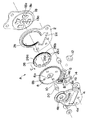
図1乃至図4は、本発明にかかるリクライニングアジャスタAを示しており、互いに対向して一体的に連結された一対のブラケット2,4と、ブラケット2,4間に回動自在に取り付けられたウォームギヤ6と、このウォームギヤ6と噛合するはすば歯車8とを備えており、ブラケット2,4はシートクッション(図示せず)に取り付けられる一方、はすば歯車8は後述するように複数のピン、外歯歯車及びシートバック取付ブラケットを介してシートバック(図示せず)に取り付けられる。なお、シートバックはバランススプリング(図示せず)の弾性力により常に前方に付勢されている。また、互いに噛合するウォームギヤ6及びはすば車8は摩擦角よりも大きいリード角を有している。
Hereinafter, embodiments of the present invention will be described with reference to the drawings.
1 to 4 show a reclining adjuster A according to the present invention, which is attached to a pair of
ウォームギヤ6の前端及び後端は、前部軸受10及び後部軸受12にそれぞれ回動自在に支持されており、前部軸受10及び後部軸受12はブラケット2,4に保持されている。また、ブラケット2,4は、ウォームギヤ6と対向する部位に穿設された矩形開口2a,4aを有し、ウォームギヤ6の一部が矩形開口2a,4aより外部に突き出ることでウォームギヤ6とブラケット2,4との干渉を防止している。すなわち、ブラケット2,4に矩形開口2a,4aを設けることによりブラケット2,4の離間距離を短く設定している。
The front end and the rear end of the
前部軸受10の近傍に位置するウォームギヤ6の刃先面には、被ロック部としてのギヤ状の多数のノッチ6aが形成され、これらノッチ6aに対し下方から対向し、必要に応じ噛合するロック爪14aを有するロック部材14がブラケット2,4間に介装され、取付軸16回りに揺動自在に取り付けられている。ロック部材14は、手動操作によりロック爪14aを上下動させてロック爪14aのノッチ6aに対するロックあるいはロック解除を行う操作レバー(図示せず)に連結されており、コイルスプリング等の付勢手段(図示せず)によりロック爪14aは常に上方(ロック方向)に付勢されている。
A number of gear-shaped notches 6a as locked portions are formed on the cutting edge surface of the
また、ブラケット4及びはすば歯車8の中心には円孔4b,8aが穿設されており、一端が円孔4bに嵌入し,中間部が円孔8aに遊挿された中心軸20廻りにはすば歯車8は回動自在に取り付けられている。また、中心軸20の他端(ブラケット2側の端部)にはシートバック取付ブラケット18が回動自在に取り付けられており、シートバック取付ブラケット18にシートバックは取り付けられている。さらに、円孔8aの周囲には複数(例えば、四つ)のピン孔8bが所定の間隔で穿設されており、各ピン孔8bにピン22の一端が嵌入している。
Further, circular holes 4b and 8a are formed in the center of the bracket 4 and the
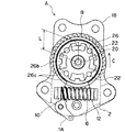
はすば歯車8とシートバック取付ブラケット18との間には、ブラケット2に形成された内歯2bと大荷重入力時に噛合する外歯歯車26が設けられており、外歯歯車26の外周面に形成された外歯26aの内側には中心部に向かって突出する複数の凸部が形成されている。これらの凸部は、円周方向に沿って所定の間隔で形成された複数(例えば、四つ)の略矩形状の第1の凸部26bと、隣接する二つの第1の凸部26bの間に形成された二つの山形状の第2の凸部26cからなり、はすば歯車8のピン孔8bに一端が嵌入した各ピン22の他端は、二つの第2の凸部26c間の凹部26dに嵌入している。
Between the
また、シートバック取付ブラケット18には、その中心部に中心軸20の端部が遊挿される円孔18aが形成され、円孔18aの周囲には例えばプレス成形によりはすば歯車8に向かって凸状に形成された略U字状の複数(外歯歯車26の第1の凸部26bと同数)の突設部18bが円周方向に沿って所定の間隔で設けられており、各突設部18bには、外歯歯車26の第1の凸部26bと相補形状の凹部18cが形成されている。
Further, the seat
この凹部18cに、外歯歯車26の第1の凸部26bが嵌入することで、はすば歯車8と外歯歯車26とシートバック取付ブラケット18とシートバックは中心軸20廻りに一体的に回動自在に構成されており、外歯歯車26は、その外歯26aがブラケット2の内歯2bと所定間隔だけ離間した状態でブラケット2に同心状に内装されている。なお、ウォームギヤ6の上方に位置する内歯2bは、ウォームギヤ6との干渉を避けるため、その一部(下部)が切り欠かかれている。
The
上記構成のリクライニングアジャスタAの作用につき以下説明する。
ロック部材14に連結された操作レバーを操作しない通常の状態では、コイルスプリング等の付勢手段の弾性力によりロック部材14は矢印B方向に付勢されており、ロック爪14aはウォームギヤ6のノッチ6aの一つと噛合している。したがって、ウォームギヤ6は回転できない状態にあり、ウォームギヤ6と噛合するはすば歯車8の回転も阻止されている。また、外歯歯車26はピン22を介してはすば歯車8に一体的に固定されるとともに、外歯歯車26の第1の凸部26bとシートバック取付ブラケット18の突設部18bとが嵌合していることから、シートバックのシートクッションに対する傾斜角は所定の角度に保持されている。
The operation of the reclining adjuster A having the above configuration will be described below.
In a normal state where the operation lever connected to the
シートバックの傾斜角を変更したい場合、操作レバーを操作して付勢手段の弾性力に抗してロック部材14を矢印Bの逆方向に回転させると、ロック爪14aとウォームギヤ6のノッチ6aとの噛合が解除されるので、ウォームギヤ6は自由に回動できる状態となる。
When it is desired to change the inclination angle of the seat back, the lock claw 14a and the notch 6a of the
ここで、互いに噛合するウォームギヤ6とはすば歯車8のリード角は摩擦角よりも大きく設定されており、はすば歯車8に中心軸20廻りの回転力が加わるとウォームギヤ6が回転するので、シートバックはバランススプリングの弾性力により前倒するか、あるいは、バランススプリングの弾性力に抗して着座者がシートバックに後方への荷重を加えることにより後倒する。所望の位置で操作レバーから手を離すと、付勢手段の弾性力によりロック部材14のロック爪14aがウォームギヤ6のノッチ6aの一つと再び噛合してウォームギヤ6の回転が阻止されるので、シートバックの傾斜角は現在の角度に保持される。
Here, the lead angle of the
次に、車両の衝突等によりシートバックに所定値以上の大荷重が入力された場合につき説明する。 Next, a case where a large load exceeding a predetermined value is input to the seat back due to a vehicle collision or the like will be described.
通常使用時にシートバックに加わる荷重以上の大荷重がシートバックに加わると、その荷重はシートバックからシートバック取付ブラケット18、外歯歯車26、ピン22、はすば歯車8の順に伝達される。この時、はすば歯車8はウォームギヤ6と噛合しており、その回転は阻止されているので、外歯歯車26の第2の凸部26cの内面とピン22との当接面に大荷重が加わることになる。
When a load greater than the load applied to the seat back during normal use is applied to the seat back, the load is transmitted from the seat back to the seat back mounting
すなわち、シートバックに車両前方への大荷重が加わると、ピン22のC方向に隣接する第2の凸部26cに大荷重が加わる一方、シートバックに車両後方への大荷重が加わると、ピン22のC方向とは逆方向に隣接する第2の凸部26cに大荷重が加わることになる。その結果、各ピン22の両側に位置する二つの第2の凸部26cのいずれか一方が外側に押圧されて変形し、その半径方向の外側に位置する歯面が外側に移動してブラケット2の内歯2bと噛合するので、シートバックはそれ以上前倒あるいは後倒することはない。
That is, when a large load is applied to the front of the vehicle on the seat back, a large load is applied to the second
換言すると、車両の衝突等により車体に大きな減加速度が入力されても、ピン22、外歯歯車26、内歯2b等により構成される補助ロック機構によりシートバックの急激な前倒あるいは後倒は防止される。
In other words, even if a large deceleration is input to the vehicle body due to a vehicle collision or the like, the seat back is suddenly moved forward or backward by the auxiliary lock mechanism including the
なお、上記構成は、上述したように、通常着座時においてシートバック取付ブラケット18の突設部18bと外歯歯車26の第1の凸部26bとの嵌合によりシートバックは所定の傾斜角度に維持されているが、この嵌合部と中心軸20の軸心までの距離L(図4参照)を比較的長く設定できることから、簡素な構成で強度向上を図ることができる。
Note that, as described above, in the above-described configuration, the seat back is kept at a predetermined inclination angle by fitting the protruding
本発明にかかるリクライニングアジャスタは、通常使用時に必要な強度を有するセクタギヤとウォームギヤを使用しながら大荷重にも耐えうる構成を有しているので、衝突等により大荷重が加わる車両用シート等に有用である。 The reclining adjuster according to the present invention has a structure capable of withstanding a heavy load while using a sector gear and a worm gear having a strength required in normal use, and is therefore useful for a vehicle seat or the like to which a heavy load is applied due to a collision or the like. It is.
2,4 ブラケット、 2a,4a 矩形開口、 2b 内歯、 4b 円孔、
6 ウォームギヤ、 6a ノッチ、 8 はすば歯車、 8a 円孔、
8b ピン孔、 10 前部軸受、 12 後部軸受、 14 ロック部材、
14a ロック爪、 16 取付軸、 18 シートバック取付ブラケット、
18a 円孔、 18b 突設部、 18c 凹部、 20 中心軸、 22 ピン、
26 外歯歯車、 26a 外歯、 26b 第1の凸部、 26c 第2の凸部、
26d 凹部、 A リクライニングアジャスタ。
2,4 bracket, 2a, 4a rectangular opening, 2b internal teeth, 4b circular hole,
6 Worm gear, 6a Notch, 8 Helical gear, 8a Circular hole,
8b pin hole, 10 front bearing, 12 rear bearing, 14 lock member,
14a lock claw, 16 mounting shaft, 18 seat back mounting bracket,
18a circular hole, 18b projecting part, 18c concave part, 20 central axis, 22 pin,
26 external gear, 26a external tooth, 26b first convex part, 26c second convex part,
26d recess, A reclining adjuster.
Claims (3)
シートクッションに回動自在に取り付けられたウォームギヤと、該ウォームギヤと噛合しシートバックに補助ロック機構を介して取り付けられたはすば歯車とを備え、上記補助ロック機構が、上記はすば歯車に連結されシートバックの一部と嵌合する外歯歯車と、シートクッションに取り付けられ上記外歯歯車を内装する内歯とを有し、通常使用時は上記ウォームギヤと上記はすば歯車との噛合により上記シートバックを上記シートクッションに対し所定の角度で保持する一方、上記シートバックに所定値以上の荷重が入力された場合には上記外歯歯車の一部を変形させて上記内歯と噛合させることにより上記シートバックを上記シートクッションに対し所定の角度で保持するようにしたことを特徴とするリクライニングアジャスタ。 A reclining adjuster for appropriately adjusting the inclination angle of the seat back with respect to the seat cushion,
A worm gear rotatably attached to a seat cushion, and a helical gear meshing with the worm gear and attached to a seat back via an auxiliary lock mechanism, the auxiliary lock mechanism being attached to the helical gear. It has an external gear that is connected and fits with a part of the seat back, and an internal tooth that is attached to the seat cushion and houses the external gear. In normal use, the worm gear and the helical gear mesh with each other. While the seat back is held at a predetermined angle with respect to the seat cushion, when a load greater than a predetermined value is input to the seat back, a part of the external gear is deformed to mesh with the internal teeth. A reclining adjuster characterized in that the seat back is held at a predetermined angle with respect to the seat cushion.
Two second protrusions are formed between the two adjacent first protrusions, and the other end of the pin whose one end is connected to the helical gear is connected to the recess between the two second protrusions. The reclining adjuster according to claim 2, wherein the reclining adjuster is inserted into the reclining adjuster.
Priority Applications (1)
| Application Number | Priority Date | Filing Date | Title |
|---|---|---|---|
| JP2004167136A JP4512423B2 (en) | 2004-06-04 | 2004-06-04 | Reclining adjuster |
Applications Claiming Priority (1)
| Application Number | Priority Date | Filing Date | Title |
|---|---|---|---|
| JP2004167136A JP4512423B2 (en) | 2004-06-04 | 2004-06-04 | Reclining adjuster |
Publications (3)
| Publication Number | Publication Date |
|---|---|
| JP2005342303A JP2005342303A (en) | 2005-12-15 |
| JP2005342303A5 JP2005342303A5 (en) | 2007-07-05 |
| JP4512423B2 true JP4512423B2 (en) | 2010-07-28 |
Family
ID=35495194
Family Applications (1)
| Application Number | Title | Priority Date | Filing Date |
|---|---|---|---|
| JP2004167136A Expired - Fee Related JP4512423B2 (en) | 2004-06-04 | 2004-06-04 | Reclining adjuster |
Country Status (1)
| Country | Link |
|---|---|
| JP (1) | JP4512423B2 (en) |
Families Citing this family (2)
| Publication number | Priority date | Publication date | Assignee | Title |
|---|---|---|---|---|
| CN104088995A (en) * | 2014-07-04 | 2014-10-08 | 巢湖市金业电工机械有限公司 | Worm wheel and worm angle adjustment device |
| KR102111294B1 (en) * | 2019-05-15 | 2020-05-15 | 주식회사 만도 | Steer-by-wire type power steering apparatus |
Citations (4)
| Publication number | Priority date | Publication date | Assignee | Title |
|---|---|---|---|---|
| JPH0739600U (en) * | 1993-12-30 | 1995-07-18 | 株式会社タチエス | Emergency locking device for vehicle seats |
| JPH09131240A (en) * | 1995-11-08 | 1997-05-20 | Ikeda Bussan Co Ltd | Inner tooth type reclining device |
| JP2000245561A (en) * | 1999-02-25 | 2000-09-12 | Bertrand Faure Equip Sa | Pivot mechanism for vehicle seat and seat having the same |
| JP2000342371A (en) * | 1999-06-08 | 2000-12-12 | Delta Tooling Co Ltd | Backlash reducing structure for reclining adjuster |
-
2004
- 2004-06-04 JP JP2004167136A patent/JP4512423B2/en not_active Expired - Fee Related
Patent Citations (4)
| Publication number | Priority date | Publication date | Assignee | Title |
|---|---|---|---|---|
| JPH0739600U (en) * | 1993-12-30 | 1995-07-18 | 株式会社タチエス | Emergency locking device for vehicle seats |
| JPH09131240A (en) * | 1995-11-08 | 1997-05-20 | Ikeda Bussan Co Ltd | Inner tooth type reclining device |
| JP2000245561A (en) * | 1999-02-25 | 2000-09-12 | Bertrand Faure Equip Sa | Pivot mechanism for vehicle seat and seat having the same |
| JP2000342371A (en) * | 1999-06-08 | 2000-12-12 | Delta Tooling Co Ltd | Backlash reducing structure for reclining adjuster |
Also Published As
| Publication number | Publication date |
|---|---|
| JP2005342303A (en) | 2005-12-15 |
Similar Documents
| Publication | Publication Date | Title |
|---|---|---|
| JP4528041B2 (en) | Reclining adjuster | |
| JP5008671B2 (en) | Vehicle seat fitting | |
| JP4335252B2 (en) | Fixing and tilt adjustment device for mounting bracket | |
| JP4184775B2 (en) | Reclining adjuster | |
| US20100056317A1 (en) | Adjuster | |
| JP2009509597A (en) | Vehicle seat fittings | |
| JP2009509596A5 (en) | ||
| JP2008516651A (en) | Vehicle seat fittings | |
| EP0617676A1 (en) | Double enveloping worm and gear seat recliner | |
| US20030222193A1 (en) | Ratchet-type lever mechanism for seat lifter | |
| JPH09308541A (en) | Inner gearing reclining device | |
| JP2008265365A (en) | Height mechanism of vehicle seat | |
| JP3415057B2 (en) | Seat lifter and ratchet lever mechanism | |
| JP6750471B2 (en) | Vehicle seat | |
| JP5531875B2 (en) | Vehicle seat coupling device and vehicle seat | |
| JP4336218B2 (en) | Reclining device | |
| JP4512423B2 (en) | Reclining adjuster | |
| JP3755858B2 (en) | Reclining device | |
| WO2012001769A1 (en) | Seat reclining device for tiltably holding seat back | |
| KR101659231B1 (en) | Recliner of vehicle seat | |
| AU2004228432A1 (en) | An infinitely variable continuous recliner mechanism for vehicle seats and similar applications | |
| JP4596694B2 (en) | Reclining device | |
| JP4545523B2 (en) | Reclining device | |
| JP2004314749A (en) | Electric reclining adjuster | |
| JP2014040133A (en) | Vehicle seat |
Legal Events
| Date | Code | Title | Description |
|---|---|---|---|
| A521 | Written amendment |
Free format text: JAPANESE INTERMEDIATE CODE: A523 Effective date: 20070523 |
|
| A621 | Written request for application examination |
Free format text: JAPANESE INTERMEDIATE CODE: A621 Effective date: 20070523 |
|
| RD03 | Notification of appointment of power of attorney |
Free format text: JAPANESE INTERMEDIATE CODE: A7423 Effective date: 20070523 |
|
| A977 | Report on retrieval |
Free format text: JAPANESE INTERMEDIATE CODE: A971007 Effective date: 20100419 |
|
| TRDD | Decision of grant or rejection written | ||
| A01 | Written decision to grant a patent or to grant a registration (utility model) |
Free format text: JAPANESE INTERMEDIATE CODE: A01 Effective date: 20100427 |
|
| A01 | Written decision to grant a patent or to grant a registration (utility model) |
Free format text: JAPANESE INTERMEDIATE CODE: A01 |
|
| A61 | First payment of annual fees (during grant procedure) |
Free format text: JAPANESE INTERMEDIATE CODE: A61 Effective date: 20100510 |
|
| FPAY | Renewal fee payment (event date is renewal date of database) |
Free format text: PAYMENT UNTIL: 20130514 Year of fee payment: 3 |
|
| R150 | Certificate of patent or registration of utility model |
Ref document number: 4512423 Country of ref document: JP Free format text: JAPANESE INTERMEDIATE CODE: R150 Free format text: JAPANESE INTERMEDIATE CODE: R150 |
|
| FPAY | Renewal fee payment (event date is renewal date of database) |
Free format text: PAYMENT UNTIL: 20130514 Year of fee payment: 3 |
|
| FPAY | Renewal fee payment (event date is renewal date of database) |
Free format text: PAYMENT UNTIL: 20140514 Year of fee payment: 4 |
|
| R250 | Receipt of annual fees |
Free format text: JAPANESE INTERMEDIATE CODE: R250 |
|
| R250 | Receipt of annual fees |
Free format text: JAPANESE INTERMEDIATE CODE: R250 |
|
| R250 | Receipt of annual fees |
Free format text: JAPANESE INTERMEDIATE CODE: R250 |
|
| R250 | Receipt of annual fees |
Free format text: JAPANESE INTERMEDIATE CODE: R250 |
|
| R250 | Receipt of annual fees |
Free format text: JAPANESE INTERMEDIATE CODE: R250 |
|
| R250 | Receipt of annual fees |
Free format text: JAPANESE INTERMEDIATE CODE: R250 |
|
| LAPS | Cancellation because of no payment of annual fees |