JP4512011B2 - Internal combustion engine - Google Patents
Internal combustion engine Download PDFInfo
- Publication number
- JP4512011B2 JP4512011B2 JP2005250152A JP2005250152A JP4512011B2 JP 4512011 B2 JP4512011 B2 JP 4512011B2 JP 2005250152 A JP2005250152 A JP 2005250152A JP 2005250152 A JP2005250152 A JP 2005250152A JP 4512011 B2 JP4512011 B2 JP 4512011B2
- Authority
- JP
- Japan
- Prior art keywords
- chamber
- piston
- vent hole
- crankcase
- crank chamber
- Prior art date
- Legal status (The legal status is an assumption and is not a legal conclusion. Google has not performed a legal analysis and makes no representation as to the accuracy of the status listed.)
- Expired - Fee Related
Links
Images


Classifications
-
- F—MECHANICAL ENGINEERING; LIGHTING; HEATING; WEAPONS; BLASTING
- F01—MACHINES OR ENGINES IN GENERAL; ENGINE PLANTS IN GENERAL; STEAM ENGINES
- F01M—LUBRICATING OF MACHINES OR ENGINES IN GENERAL; LUBRICATING INTERNAL COMBUSTION ENGINES; CRANKCASE VENTILATING
- F01M13/00—Crankcase ventilating or breathing
-
- F—MECHANICAL ENGINEERING; LIGHTING; HEATING; WEAPONS; BLASTING
- F02—COMBUSTION ENGINES; HOT-GAS OR COMBUSTION-PRODUCT ENGINE PLANTS
- F02F—CYLINDERS, PISTONS OR CASINGS, FOR COMBUSTION ENGINES; ARRANGEMENTS OF SEALINGS IN COMBUSTION ENGINES
- F02F7/00—Casings, e.g. crankcases or frames
- F02F7/0065—Shape of casings for other machine parts and purposes, e.g. utilisation purposes, safety
Description
本発明は、内燃機関、特に密封状クランク室を備えた四サイクル内燃機関に関する。 The present invention relates to an internal combustion engine, and more particularly to a four-cycle internal combustion engine having a sealed crank chamber.
従来、密閉状のクランク室を備えたドライサンプ式の潤滑手段を備えた内燃機関において、前記クランク室12とオイル室13とを区画する隔壁14に一方向弁16を設け、ピストン32の下降による、クランク室12内の圧力で、クランク室12内のオイルをオイル室13に送給するようにし、また、シリンダ壁に、シリンダ内とオイル室13とを連通するバランシング孔22を設けたものは公知である(特許文献1参照)。
ところで、前記特許文献1のものは、バランシング孔は、ピストンが往復摺動するシリンダ壁の途中に設けられていることから、ピストンが下死点から上昇する初期段階では、前記バランシング孔がピストンのスカート部で塞がれることになり、クランク室の負圧が高くなり過ぎることから、機関の始動時にクランク室内の負圧に抗してクランク軸を回転させなければならず、機関の始動初期において回転変動が発生するという課題がある。 By the way, the thing of the said patent document 1 has the balancing hole provided in the middle of the cylinder wall which a piston reciprocates, and in the initial stage that a piston raises from a bottom dead center, the said balancing hole is a piston of a piston. Since the negative pressure in the crank chamber becomes too high due to blockage at the skirt, the crankshaft must be rotated against the negative pressure in the crank chamber when starting the engine. There is a problem that rotational fluctuation occurs.
本発明はかかる実情に鑑みてなされたものであり、前記課題を解決できるようにした、新規な内燃機関を提供することを目的とする。 The present invention has been made in view of such circumstances, and an object thereof is to provide a novel internal combustion engine that can solve the above-described problems.
上記目的を達成するために、請求項1記載の発明は、クランクケースに回転自在に支承されるクランク軸と、該クランクケースに連なるシリンダ内を往復運動するピストンとを連結し、前記クランクケースにより画成される密閉状クランク室に隣接して潤滑オイル室を設け、前記ピストンの往復運動に伴うクランク室の圧力変動により、該クランク室内の潤滑オイルを一方向弁を介して潤滑オイル室に送給するようにした内燃機関において、
前記クランクケースには、クランク室の内、外を連通する通気孔を設け、この通気孔は、前記ピストンが下死点より上死点に至る何れの位置にある場合にも、該ピストンにより閉塞されることがない位置に設けられ、また、前記クランク室を画成するクランクケースに回転自在に支承されるクランク軸には、コンロッドを介して前記ピストンが連結され、該クランク軸は、前記コンロッドの連結されるクランクピン部と径方向反対側にクランクウエブ部を有し、前記通気孔は、クランク軸の軸方向視で、前記クランクウエブ部の最大外径の回転軌跡内に設けられ、さらに、前記クランクウエブ部は、その軸方向視の形状が劣弧状であって、前記ピストンが下死点に位置しているときは、前記通気孔は、前記クランク軸の軸方向視で前記クランクウエブ部と重なり合うことがないことを特徴としている。
In order to achieve the above object, the invention according to claim 1 is characterized in that a crankshaft rotatably supported by a crankcase and a piston that reciprocates in a cylinder connected to the crankcase are connected to each other by the crankcase. A lubricating oil chamber is provided adjacent to the defined closed crank chamber, and the lubricating oil in the crank chamber is sent to the lubricating oil chamber through a one-way valve due to pressure fluctuations in the crank chamber caused by the reciprocating motion of the piston. In an internal combustion engine designed to supply
The crankcase is provided with a vent hole that communicates the inside and the outside of the crank chamber, and this vent hole is blocked by the piston in any position from the bottom dead center to the top dead center. The piston is connected via a connecting rod to a crankshaft which is provided at a position where the crankshaft is not provided and is rotatably supported by a crankcase defining the crank chamber, and the crankshaft is connected to the connecting rod. A crank web portion on the opposite side of the crank pin portion connected to the crank pin portion, and the vent hole is provided in a rotation locus of the maximum outer diameter of the crank web portion in the axial direction of the crank shaft, and When the crank web portion is in an arcuate shape when viewed in the axial direction and the piston is located at the bottom dead center, the vent hole is the crank shaft when viewed from the axial direction of the crankshaft. Is characterized in that do not overlap with the web portion.
上記目的を達成するために、請求項2記載の発明は、前記請求項1記載のものにおいて、前記通気孔は、前記クランク室と前記潤滑オイル室とを連通するとともに、前記クランク軸のジャーナル軸部の上方にあって該ジャーナル軸部の径方向の投影面内に位置していることを特徴としている。 In order to achieve the above object, according to a second aspect of the present invention, in the first aspect of the present invention, the vent hole communicates the crank chamber and the lubricating oil chamber, and the journal shaft of the crankshaft. It is characterized in that it is located in the radial projection plane of the journal shaft portion above the portion .
上記目的を達成するために、請求項3記載の発明は、クランクケースに回転自在に支承されるクランク軸と、該クランクケースに連なるシリンダ内を往復運動するピストンとを連結し、前記クランクケースにより画成される密閉状クランク室に隣接して潤滑オイル室を設け、前記ピストンの往復運動に伴うクランク室の圧力変動により、該クランク室内の潤滑オイルを一方向弁を介して潤滑オイル室に送給するようにした内燃機関において、
前記クランクケースには、クランク室の内、外を連通する通気孔を設け、この通気孔は、前記ピストンが下死点より上死点に至る何れの位置にある場合にも、該ピストンにより閉塞されることがない位置に設けられ、前記通気孔は、前記クランク室と前記潤滑オイル室とを連通するとともに、前記潤滑オイル室に設けた調時伝動機構の上方に設けられていて、該調時伝動機構のテンショナーアームを回動可能に支持するピボットボス部の径方向の投影面内に位置していることを特徴としている。
In order to achieve the above object, a third aspect of the invention relates to a crankshaft rotatably supported by a crankcase and a piston that reciprocates in a cylinder connected to the crankcase, and A lubricating oil chamber is provided adjacent to the defined closed crank chamber, and the lubricating oil in the crank chamber is sent to the lubricating oil chamber through a one-way valve due to pressure fluctuations in the crank chamber caused by the reciprocating motion of the piston. In an internal combustion engine designed to supply
The crankcase is provided with a vent hole that communicates the inside and the outside of the crank chamber, and this vent hole is blocked by the piston in any position from the bottom dead center to the top dead center. The vent hole communicates with the crank chamber and the lubricating oil chamber, and is provided above a timing transmission mechanism provided in the lubricating oil chamber. It is characterized in that it is located in the radial projection plane of the pivot boss part that rotatably supports the tensioner arm of the hour transmission mechanism .
上記目的を達成するために、請求項4記載の発明は、クランクケースに回転自在に支承されるクランク軸と、該クランクケースに連なるシリンダ内を往復運動するピストンとを連結し、前記クランクケースにより画成される密閉状クランク室に隣接して潤滑オイル室を設け、前記ピストンの往復運動に伴うクランク室の圧力変動により、該クランク室内の潤滑オイルを一方向弁を介して潤滑オイル室に送給するようにした内燃機関において、
前記クランクケースには、クランク室の内、外を連通する通気孔を設け、この通気孔は
、前記ピストンが下死点より上死点に至る何れの位置にある場合にも、該ピストンにより閉塞されることがない位置に設けられ、前記クランク室内において、クランク軸の上方には、バランサ軸が回転自在に設けられ、このバランサ軸に固定した、クランク軸に連動するバランサギヤの側面には、前記通気孔に対面し得る円弧状の突部が一体に設けられ、この突部は、ピストンが上死点から下死点に至る間、通気孔を塞ぐようにされていることを特徴としている。
In order to achieve the above object, a fourth aspect of the present invention relates to a crankshaft rotatably supported by a crankcase and a piston that reciprocates in a cylinder connected to the crankcase. A lubricating oil chamber is provided adjacent to the defined closed crank chamber, and the lubricating oil in the crank chamber is sent to the lubricating oil chamber through a one-way valve due to pressure fluctuations in the crank chamber caused by the reciprocating motion of the piston. In an internal combustion engine designed to supply
The crankcase is provided with a vent hole that communicates the inside and outside of the crank chamber.
When the piston is in any position from the bottom dead center to the top dead center, the piston is provided at a position where it is not blocked by the piston. Is provided on the side of the balancer gear, which is fixed to the balancer shaft and interlocks with the crankshaft, and is integrally provided with an arc-shaped projection that can face the vent hole. It is characterized by closing the vent hole from the top dead center to the bottom dead center .
前記請求項1記載の発明によれば、クランク室を画成するクランクケースには、クランク室の内、外を連通する通気孔を設け、この通気孔はピストンが下死点より上死点に至る何れの位置にある場合にも、ピストンにより閉塞されることがない位置に設けられているので、クランク室に負圧の発生する初期段階からクランク室内が必要以上に負圧になるのを緩和でき、機関の始動初期の回転変動を抑えることができる。また、前記通気孔は、クランク軸の軸方向視で、前記クランクウエブ部の最大外径の回転軌跡内に設けられているので、該通気孔を設けることでクランク室の容積を径方向に大きくしないですむ。さらに、ピストンが下死点に位置しているときは、通気孔は、クランク軸の軸方向視でクランクウエブ部と重なり合うことがないので、通気孔をクランク軸の軸方向視で、前記クランクウエブ部の最大外径の回転軌跡内に設けたにも拘らず、ピストンが下死点から上昇する負圧の発生初期段階から通気孔は露出状態を維持して負圧の発生を緩和でき、クランク室内が必要以上に負圧になるのを緩和でき、機関の始動初期の回転変動を抑えることができる。 According to the first aspect of the present invention, the crankcase that defines the crank chamber is provided with a vent hole that communicates the inside and the outside of the crank chamber, and the vent hole is located at a top dead center from the bottom dead center. Since it is provided at a position where it is not blocked by the piston in any position, it is possible to alleviate negative pressure in the crank chamber from the initial stage when negative pressure is generated in the crank chamber. It is possible to suppress rotational fluctuations at the start of the engine. Further, since the vent hole is provided in the rotation trajectory of the maximum outer diameter of the crank web portion as viewed in the axial direction of the crankshaft, the volume of the crank chamber is increased in the radial direction by providing the vent hole. I don't need to. Further, when the piston is located at the bottom dead center, the vent hole does not overlap with the crank web portion as viewed in the axial direction of the crankshaft. In spite of being provided in the rotation trajectory of the maximum outer diameter of the part, the vent hole can maintain the exposed state from the initial stage when negative pressure is generated when the piston rises from bottom dead center, and the generation of negative pressure can be reduced. It is possible to alleviate the negative pressure in the room more than necessary, and to suppress rotational fluctuations at the start of the engine.
前記請求項2記載の発明によれば、通気孔は、クランク軸のジャーナル軸部の上方にあって該ジャーナル軸部の径方向の投影面内に位置しているので、潤滑オイル室内の潤滑オイルが、機関の振動などで跳ね上がってもクランク軸により遮られて、通気孔へ近づくのを妨げることができ、潤滑オイルが潤滑オイル室からクランク室内へ流入するのを抑えることができる。 According to the second aspect of the present invention, the vent hole is located above the journal shaft portion of the crankshaft and is located in the radial projection surface of the journal shaft portion. However, even if it jumps up due to engine vibration or the like, it can be blocked by the crankshaft and prevented from approaching the vent hole, and the lubricating oil can be prevented from flowing from the lubricating oil chamber into the crank chamber.
前記請求項3記載の発明によれば、クランク室を画成するクランクケースには、クランク室の内、外を連通する通気孔を設け、この通気孔はピストンが下死点より上死点に至る何れの位置にある場合にも、ピストンにより閉塞されることがない位置に設けられているので、クランク室に負圧の発生する初期段階からクランク室内が必要以上に負圧になるのを緩和でき、機関の始動初期の回転変動を抑えることができる。また、通気孔は、潤滑オイル室に設けた調時伝動機構の上方に設けられていて、該調時伝動機構のテンショナーアームを回動可能に支持するピボットボス部の径方向の投影面内に位置しているので、潤滑オイル室内の潤滑オイルが、機関の振動などで跳ね上がっても前記ピボットボス部により遮られて、通気孔へ近づくのを妨げることができ、潤滑オイルが潤滑オイル室からクランク室内へ流入するのを抑えることができる。 According to the third aspect of the present invention, the crankcase defining the crank chamber is provided with a vent hole that communicates the inside and the outside of the crank chamber, and the vent hole is located at a top dead center from the bottom dead center. Since it is provided at a position where it is not blocked by the piston in any position, it is possible to alleviate negative pressure in the crank chamber from the initial stage when negative pressure is generated in the crank chamber. It is possible to suppress rotational fluctuations at the start of the engine. Further, the vent hole is provided above the timing transmission mechanism provided in the lubricating oil chamber, and in the radial projection plane of the pivot boss portion that rotatably supports the tensioner arm of the timing transmission mechanism. Therefore, even if the lubricating oil in the lubricating oil chamber jumps up due to the vibration of the engine etc., it can be blocked by the pivot boss part and prevent it from approaching the vent hole. Inflow into the room can be suppressed.
前記請求項4記載の発明によれば、クランク室を画成するクランクケースには、クランク室の内、外を連通する通気孔を設け、この通気孔はピストンが下死点より上死点に至る何れの位置にある場合にも、ピストンにより閉塞されることがない位置に設けられているので、クランク室に負圧の発生する初期段階からクランク室内が必要以上に負圧になるのを緩和でき、機関の始動初期の回転変動を抑えることができる。また、クランク室内において、クランク軸の上方には、バランサ軸が回転自在に設けられ、このバランサ軸に固定した、クランク軸に連動するバランサギヤの側面には、前記通気孔に対面し得る円弧状の突部が一体に設けられ、この突部は、ピストンが上死点から下死点に至る間、通気孔を塞ぐようにされているので、通気孔をクランク室の高い位置に設けることができて、該通気孔は潤滑オイル室のオイルレベルから十分な距離を確保することができ、機関の振動などで跳ね上がった潤滑オイルが潤滑オイル室からクランク室内へ流入しにくくすることがで
き、さらに既存のバランサギヤにに突部を設けるという簡単な構造で、負圧発生初期段階からクランク室内が必要以上に負圧になるのを防止しながらクランク室の加圧時の圧力損失を低減できる。
According to the fourth aspect of the present invention, the crankcase defining the crank chamber is provided with a vent hole that communicates the inside and the outside of the crank chamber, and the vent hole is located at a top dead center from the bottom dead center. Since it is provided at a position where it is not blocked by the piston in any position, it is possible to alleviate negative pressure in the crank chamber from the initial stage when negative pressure is generated in the crank chamber. It is possible to suppress rotational fluctuations at the start of the engine. Further, in the crank chamber, a balancer shaft is rotatably provided above the crankshaft, and a side surface of a balancer gear that is fixed to the balancer shaft and interlocks with the crankshaft is formed in an arc shape that can face the vent hole. The protrusion is provided integrally, and this protrusion is designed to block the vent hole while the piston moves from the top dead center to the bottom dead center, so the vent hole can be provided at a high position in the crank chamber. Thus, the vent hole can secure a sufficient distance from the oil level of the lubricating oil chamber, the lubricating oil splashed up by engine vibration or the like can be made difficult to flow into the crank chamber from the lubricating oil chamber, and The balancer gear has a simple structure in which a protrusion is provided, and the pressure loss during pressurization of the crank chamber is reduced while preventing the crank chamber from becoming unnecessarily negative from the initial stage of negative pressure generation. It can be reduced.
以下、本発明の実施の形態を、添付図面に示した本発明の実施例に基づいて以下に具体的に説明する。 DESCRIPTION OF THE PREFERRED EMBODIMENTS Embodiments of the present invention will be specifically described below based on examples of the present invention shown in the accompanying drawings.
この実施例は、自動二輪車用内燃機関に、本発明を実施した場合であり、以下の説明において、自動二輪車の前輪側を「前」、その後輪側を「後」、自動二輪車の進行方向左側を「左」、その右側を「右」とする。 This embodiment is a case where the present invention is applied to an internal combustion engine for a motorcycle. In the following description, the front wheel side of the motorcycle is “front”, the rear wheel side is “rear”, and the left side in the traveling direction of the motorcycle. Is “left” and the right side is “right”.
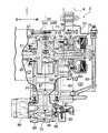
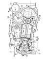
まず、図1〜11を参照して、本発明の第1実施例について説明するに、図1は、本発明内燃機関を備えた自動二輪車の全体側面図、図2は、その自動二輪車の後部の一部破断側面図、図3は、図2の3−3線に沿う拡大断面図、図4は、図3の仮想線囲い部分の拡大図、図5は、図4の5−5線に沿う断面図、図6は、図4の6−6断面図、図7は、図5の7−7線に沿う断面図、図8は、図5の8−8線に沿う断面図、図9は、図5の9−9線に沿う拡大断面図、図10は、図8の10−10線に沿う拡大断面図、図11は、ピストンが下死点にあるときの、機関要部の断面図である。 First, a first embodiment of the present invention will be described with reference to FIGS. 1 to 11. FIG. 1 is an overall side view of a motorcycle equipped with the internal combustion engine of the present invention, and FIG. 2 is a rear portion of the motorcycle. 3 is a partially broken side view, FIG. 3 is an enlarged cross-sectional view taken along line 3-3 in FIG. 2, FIG. 4 is an enlarged view of the imaginary line enclosing portion in FIG. 3, and FIG. 6 is a cross-sectional view taken along line 6-6 of FIG. 4, FIG. 7 is a cross-sectional view taken along line 7-7 of FIG. 5, and FIG. 8 is a cross-sectional view taken along line 8-8 of FIG. 9 is an enlarged cross-sectional view taken along line 9-9 in FIG. 5, FIG. 10 is an enlarged cross-sectional view taken along line 10-10 in FIG. 8, and FIG. 11 is a view of the engine when the piston is at bottom dead center. It is sectional drawing of a part.
図1,図2において、スクータ型自動二輪車は、その車体フレームFの前端のヘッドパイプ1に、前輪WFをが軸支したフロントフォーク2が操向可能に支持され、このフロントフォーク2の上部に操向ハンドル3が設けられる。また、車体フレームFの後部には、後述の懸架手段Sを介してユニットスイング式パワープユニットPUが上下にスイング可能に支承される。このユニットスイング式パワーユニットPUは、車体フレームFに対して前後方向に配置される内燃機関Eと、その内燃機関Eから後方に延長される変速機Mと、その変速機Mの後部に軸支される後輪WRとを備えている。
1 and 2, a scooter type motorcycle has a
前記懸架手段Sは、上、下リンク6,7とリヤクッション8とを備え、上リンク6は、その上端が車体フレームFに、その下端がパワーユニットPUの前方上部のハンガ部にそれぞれ前後方向に揺動可能に軸支され、また、下リンク7は、その上端がパワーユニットPUの前方下部のハンガ部に、その下端が車体フレームFにそれぞれ前後方向に揺動可能に軸支され、さらに前記リヤクッション8は、その上端が車体フレームFに、その下端がパワーユニットPUの後部にそれぞれ連結される。したがって、ユニットスイング式パワーユニットPUは、上、下リンク6,7およびリヤクッション8とよりなる懸架手段Sを介して車体フレームFに上下方向にスイング可能に懸架される、
パワーユニットPUの内燃機関Eは、四サイクル、単気筒、四バルブ、水冷、燃料噴射式であって、そのシリンダ軸線L−Lは、車体フレームFの前後方向に略水平(若干前上がりに傾斜)に延長されている。また、パワーユニットPUの変速機Mは、内燃機関Eの出力を、伝動Vベルトとコーンプーリによって無段階に変速して後輪WRに伝達する、従来公知のVベルト式無段変速機により構成される。
The suspension means S includes upper and
The internal combustion engine E of the power unit PU is a four-cycle, single-cylinder, four-valve, water-cooled, fuel-injection type, and its cylinder axis L-L is substantially horizontal in the front-rear direction of the vehicle body frame F (slightly inclined upward). Has been extended. Further, the transmission M of the power unit PU is configured by a conventionally known V-belt continuously variable transmission that continuously changes the output of the internal combustion engine E by means of a transmission V-belt and a cone pulley and transmits it to the rear wheel WR. .
図2に示すように、車体フレームF後部のシートレール5上には、タンデムシートSEが搭載されている。このタンデムシートSEは、前部シート10と後部シート12とを前後に縦列配置して構成されており、前部シート10は、その後部にバックレスト11が設けられ、また、後部シート12はその後部にバックレスト13が設けられる。また、前部シート10は、その前端が車体フレームFに上下方向の開閉可能にヒンジ連結されていて、その下に設けられる収納ボックスBの出入口を開閉可能である。タンデムシートSEの直下において、車体フレームFには、このタンデムシートSEと略同じ前後長さを有する収納ボックスBが一体に支持されており、この収納ボックスBの下に前記ユニットスイン
グ式パワーユニットPUが配置される。収納ボックスBの前部上面には、出入口が開口される。
As shown in FIG. 2, a tandem seat SE is mounted on the
つぎに、前記ユニットスイング式パワーユニットPUの構成について、主に図3〜10を参照して説明すると、このパワーユニットPUは、車体フレームFの前後方向に長く形成されていて、その駆動部を構成する内燃機関Eの機関ブロック20は、図3〜5に示すように、シリンダ21を有する単一のシリンダブロック22と、その前面(デッキ面)に接合されるシリンダヘッド23とを備えて、車体フレームFの前後方向に略水平に延長されている。また、機関ブロック20の後面(シリンダヘッド23と反対側の面)には、クランク軸25が回転自在に支承されるクランクケース24が固着され、シリンダブロック20、シリンダヘッド23およびクランクケース24の三者は、複数の通しボルト36(図4参照)により一体に結合される。
Next, the configuration of the unit swing type power unit PU will be described mainly with reference to FIGS. 3 to 10. The power unit PU is formed long in the front-rear direction of the vehicle body frame F, and constitutes a drive unit thereof. As shown in FIGS. 3 to 5, the
シリンダブロック22のシリンダ21に往復運動自在に嵌合されるピストン26と、クランク軸25のクランクピン部25pはコンロッド27を介して連接される。シリンダヘッド23の燃焼室に開口した各一対の吸気ポート28および排気ポート29には、一対の吸気バルブ30と一対の排気バルブ31がそれぞれ開閉可能に設けられ、これらのバルブ30,31には、シリンダヘッド23に設けた従来公知の動弁機構33により、通常のように所定のタイミングをもって開閉作動される。シリンダヘッド23の燃焼室には点火栓44が設けられる。シリンダヘッド23の外面には、動弁機構33を覆うヘッドカバー35が固着される。動弁機構33の動弁カム軸32は、調時伝動機構34を介してクランク軸25に連動されており、クランク軸25により1/2の減速比をもって回転駆動される。
A
図2,5に示すように、シリンダヘッド23の上部に形成される吸気ポート28には、吸気系Inが接続され、この吸気系Inは、その下流部に、燃料噴射バルブ40およびスロットルボデー41を備えて内燃機関Eの上方を後方へと延長されており、その上流端にエアクリーナ42が接続される。また、シリンダヘッド23の下部に形成される排気ポート29には、排気系Exが接続され、この排気系Exは内燃機関Eの下方を後方へと延長されており、その下流端に排気マフラー43(図1参照)が接続される。
As shown in FIGS. 2 and 5, an intake system In is connected to an
図3〜5に示すように、クランクケース24は、車体フレームFの左側の左ケース半体24Lと、車体フレームFの右側の右ケース半体24Rとによって車幅方向に分割形成されており、それらの左、右ケース半体24L,24Rは複数の連結ボルト37により一体に結合されている。クランクケース24の左右ケース半体24L,24Rは、互いに平行な左右側壁を有し、これらの左右側壁に、左右ジャーナル軸受部が一体に形成され、これらの左右ジャーナル軸受部に、車体フレームFを横切って略水平に配置されるクランク軸25がプレーン軸受50,50を介して回転自在に支承されている。
3-5, the
図3〜8に示すように、クランクケース24により画成される密封状のクランク室CCは、オイルパンを備えておらず、比較的容積が小さく形成されていて、その内部に収容されるクランク軸25のクランクピン部25pおよびクランクウエブ部25w,25wとの間に形成される間隙を可及的に小さくしてある。
As shown in FIGS. 3 to 8, the sealed crank chamber CC defined by the
図3に示すように、クランクケース24の左ケース半体24Lの外側には、伝動ケース本体64が一体的に形成され、さらに、この伝動ケース本体64の開口外側面に伝動ケースカバー65が固定されており、伝動ケース本体64と、伝動ケースカバー65とで伝動ケース66が形成される。この伝動ケース66により伝動室CTが画成される。伝動ケース66は車体フレームFの後方へと延長されていて、伝動室CT内に前記Vベルト式無段変速機Mが収容されており、この無段変速機Mの入力側には、オイルシール51を経て伝
動ケース66内に延出したクランク軸25の左側の軸端部25lが連結されている。無段変速機Mは、伝動室CT内を後方に延長されており、その出力側に、伝動ケース66に回転自在に支承されるカウンタ軸68が連結されている。このカウンタ軸68は、伝動ケース66の後部に設けた減速ギヤ群69を経て、伝動ケース66の後部に回転自在に軸架した後車軸70に連動され、この後車軸70の外端に後輪WRが一体に支持される。
As shown in FIG. 3, a transmission case
なお、前記Vベルト式無段変速機Mは従来公知のものであり、クランク軸25の回転を無段に変速して後輪WRに伝達できるようにされる。
The V-belt type continuously variable transmission M is a conventionally known one, and the rotation of the
図7,8に示すように、クランクケース24の右ケース半体24Rには、クランク軸25方向に延びる延長壁部71が一体に形成され、この延長壁部71の外側面にクランクケースカバー72が固定されている。そして、この右ケース半体24Rとクランクケースカバー72とによって、密閉状のクランク室CCに隣接する密封状の潤滑オイル室COが形成され、この潤滑オイル室COの上方には、フライホイールマグネトー75が収容され、このフライホイールマグネトー75は、右ケース半体24Rのジャーナル軸受部を貫通して潤滑オイル室CO内に延長されるクランク軸25の右側の軸端部25rが連結され、クランク軸25により駆動される。
As shown in FIGS. 7 and 8, an
図7,8に示すように、潤滑オイル室COは、クランクケース24の側方からその下方へと及んでおり、この潤滑オイル室CO内において、クランク軸25には、2つの駆動スプロケット76,77およびスタータギヤ78が固定され、一方の駆動スプロケット76には、機関ブロック20内に設けた前記調時伝動機構34(図4,6)が連結され、また、他方の駆動スプロケット77には、後述のオイルポンプ(フィードポンプ)80(図5,7)が連結され、さらに、スタータギヤ78には、スタータを駆動するスタータモータ110(図7)が連結されている。
As shown in FIGS. 7 and 8, the lubricating oil chamber CO extends from the side of the
図4,6,10に示すように、クランク軸25と動弁カム軸32とを連動する調時伝動機構34は、クランク軸25に固定される前記駆動スプロケット76と、動弁カム軸32に固定される被動スプロケット53と、それら両スプロケット76,53間に懸回される無端状伝動チエン54とより構成されており、クランク軸25の回転は、この調時伝動機構34を介して動弁カム軸32に1/2の減速比で伝達される。図6に示すように、無端状伝動チエン54の緩み側には、この伝動チエン54に所定の張力を付与するテンショナー55が設けられる。このテンショナー55は、前記伝動チエン54の緩み側の外側に沿って設けられるテンショナーアーム56と、このテンショナーアーム56を、伝動チエン54に向けて押圧調整するラッシュアジャスタ57とより構成される。図6,8,10に示すように、前記テンショナーアーム56は、その基端のピボットボス部56bが、クランク軸25の真上において、クランクケース24の右ケース半体24Rより突設したボス部59にピボットピン60をもってピボット連結されて、伝動チエン55に対して進退可能とされている。そして、テンショナーアーム56は、ラッシュアジャスタ57により伝動チエン54に向けて押圧されて、該伝動チエン54に所定の張力を付与するようにされている。また、図6に示すように、無端状伝動チエン55の張り側には、押え部材61が設けられる。
As shown in FIGS. 4, 6, and 10, the
前記内燃機関Eには、ドライサンプ式の潤滑手段が備えられる。以下に、この潤滑手段の構成について説明する。 The internal combustion engine E is provided with dry sump type lubricating means. Below, the structure of this lubricating means is demonstrated.
このドライサンプ式の潤滑手段は、オイルポンプ(フィードポンプ)80と、内燃機関Eの運転により密封状のクランク室CC内に発生する圧力変動により開閉される、一方向弁、すなわちリードバルブ102を備え、オイルポンプ80により潤滑オイル室CO内の潤滑オイルを吸い上げてクランク軸25の各被潤滑部に給油し、クランク室CCに溜まっ
た潤滑オイルをリードバルブ102の開弁により潤滑オイル室COに戻すようにされている。
This dry sump-type lubrication means includes an oil pump (feed pump) 80 and a one-way valve, that is, a
図5〜8において、前記密封状の潤滑オイル室CO内の下部には潤滑オイルが貯溜される。この潤滑オイル室CO内において、クランクケース24の右ケース半体24Rの下部には、オイルポンプ80(図8参照)が設けられる。このオイルポンプ80のポンプ軸81に固定された被動スプロケット82は、無端伝動チエーン83を介してクランク軸25と一体の前記駆動スプロケット77に連動されていて、クランク軸25により駆動される。オイルポンプ80の吸込側は、潤滑オイル室COの潤滑オイル内に浸漬されるオイルストレーナ84に連通されている。オイルポンプ80からの潤滑オイルは、油回路Ciを介してクランク軸25の被潤滑部などに給油されるようにされており、すなわち、オイルポンプ80の吐出側に連なる吐出油路85は、クランクケース24の下部一側に設けたオイルフィルタ86(図7,8参照)の入口に連通され、該オイルフィルタ86の出口は、クランクケース24の底壁に形成したメインギャラリ87に連通されている。
5 to 8, the lubricating oil is stored in the lower part of the sealed lubricating oil chamber CO. In this lubricating oil chamber CO, an oil pump 80 (see FIG. 8) is provided below the
図8に示すように、メインギャラリ87は、クランクケースカバー72およびクランクケース24に形成した第1、第2および第3の分岐油路91,92および93に分岐されている。オイルフィルタ86からの潤滑オイルは、第1、第2の分岐油路91,92からクランク軸25のジャーナル軸部25j,25jにそれぞれ給油される。また第3の分岐油路93からクランクピン部25pに給油される。
As shown in FIG. 8, the
クランク軸25のジャーナル軸部25j,25jはプレーン軸受50,50を介して回転自在に支承され、伝動室CT側のプレーン軸受50に隣接してオイルシール51が設けられる。
The
図8に示すように、油回路Ciには、油圧レギュレータ88が接続され、油回路Ci内の油圧が所定圧を越えると、油回路Ciは、油圧レギュレータ88を介して潤滑オイル室COに短絡される。
As shown in FIG. 8, a
図5,9に示すように、密封状のクランク室CCと、密閉状の潤滑オイル室COとの下部には、それらを連通する連通油路101が形成され、この連通油路101には、クランク室CC内の圧力変動により開閉される、一方向弁すなわちリードバルブ102が設けられる。内燃機関Eの運転により、密封状のクランク室CCに圧力変動が生じると、このリードバルブ102は間欠的に開弁されて、クランク室CC内の潤滑オイルを連通油路101を通して潤滑オイル室COに還流させることができる。
As shown in FIGS. 5 and 9, a
図6,10に示すように、右ケース半体24Rとクランクケースカバー72内の上部一側には、ブリーザ室105が形成されている。このブリーザ室105は、その下部の連通口106を通して循環オイル室COに連通され、また、その上部がブリーザパイプ107を通して大気に開口されており、潤滑オイル室CO内は、このブリーザ室105を通して呼吸作用がなされる。また、ブリーザ室105内は、千鳥状に配置した複数枚の邪魔板108により迷路になっており、エア中に混入するオイルミストが分離されて潤滑オイル室COに戻される。
As shown in FIGS. 6 and 10, a
図5,7に示すように、クランクケース24の上方には、スタータモータ110が橋架支持され、該スタータモータ110のモータ軸111は、クランクケース24に支持されるアイドラー112を介して前記スタータギヤ78に連動されている。
As shown in FIGS. 5 and 7, a
図5,6,8,11に示すように、互いに隣接して配置される、クランク室CCと潤滑オイル室COとを区画する隔壁、すなわちクランクケース24の右ケース半体24Rの上
部には、クランク室CC内と潤滑室CO内とを相互に連通する、小孔よりなる通気孔115が穿設されている。この通気孔115は、機関Eの運転時に、ピストン26が下死点(図11参照)から上死点(図5参照)に移動する際に、密閉状のクランク室CC内の圧力が、該機関Eの運転に支障を及ぼす程に過剰に負圧になるのを防止するためのものであり、この通気孔115の大きさは、クランク室CC内の正圧、負圧の値が略等しくなるように設定される。
As shown in FIGS. 5, 6, 8, and 11, the partition wall that is disposed adjacent to each other and that partitions the crank chamber CC and the lubricating oil chamber CO, that is, the upper portion of the
しかして、この第1実施例によれば、機関Eの全運転運状態において、前記通気孔115は、ピストン26が下死点から上昇して上死点に至る間、すなわちクランク室CC内に負圧の発生する初期段階から負圧の発生が止まる終了段階に至るまで、前記通気孔15は常に露出状態におかれ、また機関Eの運転によって、その通気孔115の良好な通気機能が妨げられないように、後記(1) 〜(4) のような工夫がされている。
Thus, according to the first embodiment, in the entire operating state of the engine E, the
(1) 図5,11に示すように、前記通気孔115は、ピストン26が下死点に位置しているときの、該ピストン26のスカート部26sから離れた、クランク室CC内の上部位置に設けられる。これにより、ピストン26が下死点から上死点に至る何れの位置にある場合(クランク室CCが負圧になる領域)にも、通気孔115は、ピストン26により閉塞されることがなく、クランク室CC内に負圧の発生する初期段階からその終了段階に至るまでクランク室CC内の負圧を緩和して、クランク室内が必要以上に負圧になるのを緩和でき、機関の始動初期の回転変動を抑えることができる。
(1) As shown in FIGS. 5 and 11, the
(2) 図5,11の示すように、前記通気孔115は、クランク室CC内において、クランク軸25の略真上にあって、該クランク軸25の軸方向視で、クランクウエブ部25wの最大外径の回転軌跡内に位置している。また、クランク軸25のクランクウエブ部25wは、そのクランクピン部25pと径方向で反対側に設けられており、クランク軸25の軸方向視で劣弧状(円弧の長さが180°よりも短い)に形成されるので、前記通気孔115をこのクランクウエブ部25wの最大外径の回転軌跡内に設けても、ピストン26が下死点から上死点に至る間、この通気孔115がクランクウエブ部25wで塞がれることがない。すなわち、図5,11において、クランク軸25が矢印a方向(反時計方向)に回転されるとき、ピストン26が下死点(図11参照)から上死点(図5参照)に至るまでに、通気孔115は、このクランクウエブ部25wで塞がることがない。したがって、その間、通気孔115は常に露出状態にあって、所期の通気作用が維持され、クランク室CC内が必要以上に負圧になるのを緩和でき、機関の始動初期の回転変動を抑えることができる。
(2) As shown in FIGS. 5 and 11, the
(3) 図5,11に示すように、通気孔115は、クランク軸25のジャーナル軸部25jの上方において、該クランク軸25のジャーナル軸部25jの径方向の投影面内に設けられる。これにより、潤滑オイル室CO内のオイル飛沫が、機関Eの揺動、振動などにより跳ね上がることがあっても、そのオイル飛沫をクランク軸25により遮ることができて、そのオイル飛沫が通気孔115の近傍に近づくのを防止することができ、潤滑オイル室CO内の飛沫オイルが通気孔115を通してクランク室CC内へ流入するのを抑制することができる。
(3) As shown in FIGS. 5 and 11, the
(4) 図6,8,10に示すように、クランク軸25のジャーナル軸部25jと、それよりも上に位置する通気孔115との間には、前記テンショナー55のピボットボス部55bが設けられ、このピボットボス部55bの径方向の投影面内に前記通気孔115が位置している。これにより、潤滑オイル室CO内の潤滑オイル飛沫が、機関Eの揺動、振動などにより跳ね上がることがあっても、そのオイル飛沫をテンショナー55のピボットボス部56bにより遮って、そのオイル飛沫が通気孔115の近傍に近づくのを防止することができ、潤滑オイル室CO内の飛沫オイルが通気孔を通してクランク室CC内へ流入する
のを防止することができる。
(4) As shown in FIGS. 6, 8, and 10, a pivot boss portion 55b of the
なお、図10に示すように、隔壁、すなわち右クランクケース半体24Rの上方の壁面には、複数の補強リブ116,117が一体に隆起されており、これらの補強リブ116,117は、前記ピボットボス部56bと共に通気孔115を下側から囲んでいるので、これらの補強リブ116,117とピボットボ部56bとでオイル飛沫の通気孔115への流入を一層確実に防止することができる。
As shown in FIG. 10, a plurality of reinforcing
つぎに、図12〜14を参照して、本発明の第2実施例について説明する。 Next, a second embodiment of the present invention will be described with reference to FIGS.
図12は、第2実施例の、前記第1実施例の図5に対応する図、図13は、図12の13−13線に沿う断面図、図14は、図13の14−14線に沿う拡大断面図であり、図中前記第1実施例と同じ要素には同じ符号が付される。 12 is a view of the second embodiment corresponding to FIG. 5 of the first embodiment, FIG. 13 is a cross-sectional view taken along line 13-13 in FIG. 12, and FIG. 14 is a line 14-14 in FIG. The same reference numerals are given to the same elements as those in the first embodiment.
この第2実施例は、クランク室CC内の上部にバランサ120が設けられる。このバランサ120のバランサ軸121の上方において、クランク室CCと潤滑オイル室COとの隔壁、すなわち右ケース半体24Rには、通気孔115が穿設される。この通気孔115はピストン26が下死点から上死点に至る間は、該通気孔115を露出状態として、クランク室CC内が必要以上の負圧になるのを緩和しながら、通気孔115への潤滑オイルの流入を防止するようにしたものである。
In the second embodiment, a
図12,13に示すように、クランク室CC内の上部において、クランクケース24の右ケース半体24Rには、前記通気孔115の下方でバランサ軸121が回転自在に支承さる。このバランサ軸121は、これと一体のバランサギヤ122と、これと噛合されるクランク軸25に固定の駆動ギヤ123を介してクランク軸25により、1:1の回転比をもって逆方向に回転駆動され、単気筒内燃機関Eの振動を打ち消すようにされる。
As shown in FIGS. 12 and 13, the
前記バランサギヤ122には、従来公知のセラシ機構125を備えている。すなわち、このバランサギヤ122は、互いに重ね合わされるメインギヤ122mとサブギヤ122sとよりなり、メインギヤ122mはバランサ軸121に固定支持され、一方、サブギヤ122sはバランサ軸12回転自在に支持される。メインギヤ122mと、サブギヤ122sとの間には、それらの間に回転方向のズレを発生させるための複数のスプリング126を設けられる。これによりバランスギヤ122と駆動ギヤ123との間のバックラッシュを無くし、同時にノイズを低減させることができる。
The
前記バランサギヤ122の側面には、半円状の突部127が一体に形成されている。この突部127は、通気孔115と対面しており、バランサギヤ122の回転で、通気孔115を塞ぐようにされている。すなわち、図12に示すように、ピストン26が上死点から下死点に移動する間は、突部127は、通気孔115を塞ぐ位置にあり、また、ピストン26が下死点から上死点に移動する間は、突部127は、通気孔115から離れて、その通気孔115の塞ぎを解除する位置にある。したがって、ピストン26が下死点から上死点に移動する負圧の発生時には、クランク室CC内が過剰に負圧になるのを防止し、またピストン26が上死点から下死点に移動する加圧時には、突部127により通気孔115を塞いで、クランク室CC内の圧力損失を低減することができる。
A
しかして、この第2実施例によれば、通気孔115は、潤滑オイルのオイルレベルとの間に距離を十分に確保して、潤滑オイルが潤滑オイル室COからクランク室CC内へ流入しにくくすることができ、また既存のバランサギヤを利用して、クランク室の加圧時の圧力損失を低減することができる。
Therefore, according to the second embodiment, the
以上、本発明の実施例について説明したが、本発明はその実施例に限定されることなく、本発明の範囲内で種々の実施例が可能である。 As mentioned above, although the Example of this invention was described, this invention is not limited to the Example, A various Example is possible within the scope of the present invention.
たとえば、前記実施例では、本発明にかかる内燃機関を自動二輪車用に実施した場合を説明したが、これを他の用途の内燃機関にも実施することができる。 For example, in the above-described embodiment, the case where the internal combustion engine according to the present invention is implemented for a motorcycle has been described, but this can also be implemented for an internal combustion engine of another application.
21・・・・・・・シリンダ
24・・・・・・・クランクケース
25・・・・・クランク軸
25j・・・・ジャーナル軸部
25p・・・・クランクピン部
25w・・・・クランクウエブ部
26・・・・・ピストン
27・・・・・コンロッド
34・・・・・調時伝動機構
56・・・・・テンショナーアーム
56b・・・・ピボットボス部
102・・・・一方向弁(リードバルブ)
115・・・・通気孔
121・・・・バランサ軸
122・・・・バランサギヤ
127・・・・突部
CC・・・・・クランク室
CO・・・・・潤滑オイル室
21 ....
115 ...
Claims (4)
前記クランクケース(24)には、クランク室(CC)の内、外を連通する通気孔(115)を設け、この通気孔(115)は、前記ピストン(26)が下死点より上死点に至る何れの位置にある場合にも、該ピストン(26)により閉塞されることがない位置に設けられ、
また、前記クランク室(CC)を画成するクランクケース(24)に回転自在に支承されるクランク軸(25)には、コンロッド(27)を介して前記ピストン(26)が連結され、該クランク軸(25)は、前記コンロッド(27)の連結されるクランクピン部(25p)と径方向反対側にクランクウエブ部(25w)を有し、前記通気孔(115)は、クランク軸(25)の軸方向視で、前記クランクウエブ部(25w)の最大外径の回転軌跡内に設けられ、
さらに、前記クランクウエブ部(25w)は、その軸方向視の形状が劣弧状であって、前記ピストン(26)が下死点に位置しているときは、前記通気孔(115)は、前記クランク軸(25)の軸方向視で前記クランクウエブ部(25w)と重なり合うことがないことを特徴とする、内燃機関。 A crankshaft (25) rotatably supported by the crankcase (24) and a piston (26) reciprocating in a cylinder (21) connected to the crankcase (24) are connected, and the crankcase (24 ), A lubricating oil chamber (CO) is provided adjacent to the closed crank chamber (CC) defined by the cylinder chamber (CC), and the crank chamber (CC) is caused by pressure fluctuations in the crank chamber (CC) accompanying the reciprocating motion of the piston (26). In the internal combustion engine in which the lubricating oil in CC) is supplied to the lubricating oil chamber (CO) via the one-way valve (102),
The crankcase (24) is provided with a vent hole (115) that communicates the inside and outside of the crank chamber (CC), and the vent hole (115) is such that the piston (26) is above the top dead center from the bottom dead center. Is provided at a position where it is not blocked by the piston (26),
The piston (26) is connected via a connecting rod (27) to a crankshaft (25) rotatably supported by a crankcase (24) defining the crank chamber (CC). The shaft (25) has a crank web portion (25w) on the opposite side to the crank pin portion (25p) to which the connecting rod (27) is connected, and the vent hole (115) is formed on the crankshaft (25). The crank web portion (25w) is provided in the rotation locus of the maximum outer diameter as viewed in the axial direction of
Further, the crank web portion (25w) has an inferior arc shape when viewed in the axial direction, and when the piston (26) is located at the bottom dead center, the vent hole (115) An internal combustion engine characterized by not overlapping with the crank web portion (25w) as viewed in the axial direction of the crankshaft (25) .
オイル室(CO)を設け、前記ピストン(26)の往復運動に伴うクランク室(CC)の圧力変動により、該クランク室(CC)内の潤滑オイルを一方向弁(102)を介して潤滑オイル室(CO)に送給するようにした内燃機関において、
前記クランクケース(24)には、クランク室(CC)の内、外を連通する通気孔(115)を設け、この通気孔(115)は、前記ピストン(26)が下死点より上死点に至る何れの位置にある場合にも、該ピストン(26)により閉塞されることがない位置に設けられ、
前記通気孔(115)は、前記クランク室(CC)と前記潤滑オイル室(CO)とを連通するとともに、前記潤滑オイル室(CO)に設けた調時伝動機構(34)の上方に設けられていて、該調時伝動機構(34)のテンショナーアーム(56)を回動可能に支持するピボットボス部(56b)の径方向の投影面内に位置していることを特徴とする、内燃機関。 A crankshaft (25) rotatably supported by the crankcase (24) and a piston (26) reciprocating in a cylinder (21) connected to the crankcase (24) are connected, and the crankcase (24 ) Lubricated adjacent to the closed crank chamber (CC) defined by
An oil chamber (CO) is provided, and the lubricating oil in the crank chamber (CC) is lubricated through the one-way valve (102) due to pressure fluctuations in the crank chamber (CC) accompanying the reciprocating motion of the piston (26). In an internal combustion engine that is fed to a chamber (CO),
The crankcase (24) is provided with a vent hole (115) that communicates the inside and outside of the crank chamber (CC), and the vent hole (115) is such that the piston (26) is above the top dead center from the bottom dead center. Is provided at a position where it is not blocked by the piston (26),
The vent hole (115) communicates the crank chamber (CC) and the lubricating oil chamber (CO), and is provided above a timing transmission mechanism (34) provided in the lubricating oil chamber (CO). It has been, and being located in該調transmission mechanism (34) of the tensioner arm (56) pivot boss rotatably supporting (56b) radial projection plane of the inner combustion organ.
前記クランクケース(24)には、クランク室(CC)の内、外を連通する通気孔(115)を設け、この通気孔(115)は、前記ピストン(26)が下死点より上死点に至る何れの位置にある場合にも、該ピストン(26)により閉塞されることがない位置に設けられ、
前記クランク室(CC)内において、クランク軸(25)の上方には、バランサ軸(121)が回転自在に設けられ、このバランサ軸(121)に固定した、クランク軸(25)に連動するバランサギヤ(122)の側面には、前記通気孔(115)に対面し得る円弧状の突部(127)が一体に設けられ、この突部(127)は、ピストン(26)が上死点から下死点に至る間、通気孔(115)を塞ぐようにされていることを特徴とする、内燃機関。 A crankshaft (25) rotatably supported by the crankcase (24) and a piston (26) reciprocating in a cylinder (21) connected to the crankcase (24) are connected, and the crankcase (24 ), A lubricating oil chamber (CO) is provided adjacent to the closed crank chamber (CC) defined by the cylinder chamber (CC), and the crank chamber (CC) is caused by pressure fluctuations in the crank chamber (CC) accompanying the reciprocating motion of the piston (26). In the internal combustion engine in which the lubricating oil in CC) is supplied to the lubricating oil chamber (CO) via the one-way valve (102),
The crankcase (24) is provided with a vent hole (115) that communicates the inside and outside of the crank chamber (CC), and the vent hole (115) is such that the piston (26) is above the top dead center from the bottom dead center. Is provided at a position where it is not blocked by the piston (26),
In the crank chamber (CC), a balancer shaft (121) is rotatably provided above the crankshaft (25), and is a balancer gear fixed to the balancer shaft (121) and interlocking with the crankshaft (25). An arcuate protrusion (127) that can face the vent hole (115) is integrally provided on the side surface of (122), and the piston (26) is located below the top dead center in the protrusion (127). while fatal point, characterized in that it is adapted to close the vent hole (115), an inner combustion engine.
Priority Applications (2)
| Application Number | Priority Date | Filing Date | Title |
|---|---|---|---|
| JP2005250152A JP4512011B2 (en) | 2005-08-30 | 2005-08-30 | Internal combustion engine |
| ES200601990A ES2319360B2 (en) | 2005-08-30 | 2006-07-25 | INTERNAL COMBUSTION ENGINE. |
Applications Claiming Priority (1)
| Application Number | Priority Date | Filing Date | Title |
|---|---|---|---|
| JP2005250152A JP4512011B2 (en) | 2005-08-30 | 2005-08-30 | Internal combustion engine |
Publications (3)
| Publication Number | Publication Date |
|---|---|
| JP2007064081A JP2007064081A (en) | 2007-03-15 |
| JP2007064081A5 JP2007064081A5 (en) | 2008-07-03 |
| JP4512011B2 true JP4512011B2 (en) | 2010-07-28 |
Family
ID=37926570
Family Applications (1)
| Application Number | Title | Priority Date | Filing Date |
|---|---|---|---|
| JP2005250152A Expired - Fee Related JP4512011B2 (en) | 2005-08-30 | 2005-08-30 | Internal combustion engine |
Country Status (2)
| Country | Link |
|---|---|
| JP (1) | JP4512011B2 (en) |
| ES (1) | ES2319360B2 (en) |
Families Citing this family (11)
| Publication number | Priority date | Publication date | Assignee | Title |
|---|---|---|---|---|
| JP5119141B2 (en) * | 2008-12-26 | 2013-01-16 | 川崎重工業株式会社 | Vehicle with engine |
| JP5225910B2 (en) * | 2009-03-27 | 2013-07-03 | 本田技研工業株式会社 | Internal combustion engine |
| JP2011038437A (en) | 2009-08-07 | 2011-02-24 | Suzuki Motor Corp | Internal combustion engine |
| US8833328B2 (en) | 2010-12-29 | 2014-09-16 | Ford Global Technologies, Llc | Structural frame |
| US8887703B2 (en) | 2011-10-10 | 2014-11-18 | Ford Global Technologies, Llc | Integrated positive crankcase ventilation vent |
| CN103306845B (en) * | 2013-06-28 | 2015-05-20 | 力帆实业(集团)股份有限公司 | Right crankcase of engine |
| CN103321771B (en) * | 2013-06-28 | 2015-07-01 | 力帆实业(集团)股份有限公司 | Left crankcase for engines |
| JP6029705B2 (en) * | 2015-03-31 | 2016-11-24 | 本田技研工業株式会社 | Oil discharge structure from crank chamber in internal combustion engine |
| JP6549659B2 (en) * | 2017-08-21 | 2019-07-24 | 本田技研工業株式会社 | Breather device for internal combustion engine |
| JP2020084976A (en) * | 2018-11-30 | 2020-06-04 | 本田技研工業株式会社 | Internal combustion engine |
| JP7472756B2 (en) | 2020-10-27 | 2024-04-23 | スズキ株式会社 | engine |
Citations (2)
| Publication number | Priority date | Publication date | Assignee | Title |
|---|---|---|---|---|
| JPH0363710U (en) * | 1989-10-24 | 1991-06-21 | ||
| JP2005030304A (en) * | 2003-07-14 | 2005-02-03 | Yamaha Motor Co Ltd | Lubrication device of dry sump type four-cycle engine |
Family Cites Families (5)
| Publication number | Priority date | Publication date | Assignee | Title |
|---|---|---|---|---|
| JPS58113522A (en) * | 1981-12-28 | 1983-07-06 | Fuji Heavy Ind Ltd | Oil returning device of internal-combustion engine |
| JPS58200019A (en) * | 1982-05-18 | 1983-11-21 | Fuji Heavy Ind Ltd | Internal-combustion engine |
| DE3727073C2 (en) * | 1986-08-27 | 1994-08-11 | Volkswagen Ag | Crankcase for an internal combustion engine with a ventilation duct |
| JP2769984B2 (en) * | 1994-12-22 | 1998-06-25 | リョービ株式会社 | Blow-by gas discharge structure |
| JP3965960B2 (en) * | 2001-10-12 | 2007-08-29 | スズキ株式会社 | Breather equipment for motorcycles |
-
2005
- 2005-08-30 JP JP2005250152A patent/JP4512011B2/en not_active Expired - Fee Related
-
2006
- 2006-07-25 ES ES200601990A patent/ES2319360B2/en not_active Expired - Fee Related
Patent Citations (2)
| Publication number | Priority date | Publication date | Assignee | Title |
|---|---|---|---|---|
| JPH0363710U (en) * | 1989-10-24 | 1991-06-21 | ||
| JP2005030304A (en) * | 2003-07-14 | 2005-02-03 | Yamaha Motor Co Ltd | Lubrication device of dry sump type four-cycle engine |
Also Published As
| Publication number | Publication date |
|---|---|
| ES2319360B2 (en) | 2010-01-11 |
| ES2319360A1 (en) | 2009-05-06 |
| JP2007064081A (en) | 2007-03-15 |
Similar Documents
| Publication | Publication Date | Title |
|---|---|---|
| JP4512011B2 (en) | Internal combustion engine | |
| JP4139779B2 (en) | engine | |
| US7334556B2 (en) | Engine configuration for a motorcycle | |
| CA2599824C (en) | Oil filter mounting structure in internal combustion engine | |
| JP3891756B2 (en) | Lubrication structure of internal combustion engine | |
| JP4546206B2 (en) | Motorcycle | |
| JP2003129819A (en) | Breather device for four-cycle engine | |
| JP3746015B2 (en) | Dry sump 4-cycle engine | |
| JP5119141B2 (en) | Vehicle with engine | |
| JP2002235548A (en) | Parallel four cylinder engine | |
| JP7382163B2 (en) | hybrid vehicle | |
| JP7208865B2 (en) | Straddle vehicle | |
| JP4530782B2 (en) | Engine oil passage structure | |
| JP2011190787A (en) | Blow-by gas ventilation structure of internal combustion engine | |
| WO2011132574A1 (en) | Engine oil passage structure | |
| JP2021008218A (en) | Hybrid vehicle | |
| JP4066677B2 (en) | Engine lubrication equipment | |
| JP3657303B2 (en) | Engine lubrication equipment | |
| JP4467377B2 (en) | Motorcycle unit swing type power unit | |
| JP5823360B2 (en) | Lubricating oil supply structure for internal combustion engines | |
| JP5353538B2 (en) | Cam chain lubrication structure for motorcycle engines | |
| JP2006090241A (en) | Four-cycle engine for motorcycle | |
| JP3445263B2 (en) | Water-cooled parallel 4-cylinder engine | |
| JP3549605B2 (en) | Engine generator layout | |
| JP5225910B2 (en) | Internal combustion engine |
Legal Events
| Date | Code | Title | Description |
|---|---|---|---|
| A521 | Written amendment |
Free format text: JAPANESE INTERMEDIATE CODE: A523 Effective date: 20080516 |
|
| A621 | Written request for application examination |
Free format text: JAPANESE INTERMEDIATE CODE: A621 Effective date: 20080516 |
|
| A977 | Report on retrieval |
Free format text: JAPANESE INTERMEDIATE CODE: A971007 Effective date: 20100125 |
|
| A131 | Notification of reasons for refusal |
Free format text: JAPANESE INTERMEDIATE CODE: A131 Effective date: 20100203 |
|
| A521 | Written amendment |
Free format text: JAPANESE INTERMEDIATE CODE: A523 Effective date: 20100401 |
|
| TRDD | Decision of grant or rejection written | ||
| A01 | Written decision to grant a patent or to grant a registration (utility model) |
Free format text: JAPANESE INTERMEDIATE CODE: A01 Effective date: 20100428 |
|
| A01 | Written decision to grant a patent or to grant a registration (utility model) |
Free format text: JAPANESE INTERMEDIATE CODE: A01 |
|
| A61 | First payment of annual fees (during grant procedure) |
Free format text: JAPANESE INTERMEDIATE CODE: A61 Effective date: 20100507 |
|
| FPAY | Renewal fee payment (event date is renewal date of database) |
Free format text: PAYMENT UNTIL: 20130514 Year of fee payment: 3 |
|
| R150 | Certificate of patent or registration of utility model |
Free format text: JAPANESE INTERMEDIATE CODE: R150 |
|
| FPAY | Renewal fee payment (event date is renewal date of database) |
Free format text: PAYMENT UNTIL: 20130514 Year of fee payment: 3 |
|
| FPAY | Renewal fee payment (event date is renewal date of database) |
Free format text: PAYMENT UNTIL: 20140514 Year of fee payment: 4 |
|
| LAPS | Cancellation because of no payment of annual fees |