JP4507962B2 - Gas chromatograph - Google Patents
Gas chromatograph Download PDFInfo
- Publication number
- JP4507962B2 JP4507962B2 JP2005116562A JP2005116562A JP4507962B2 JP 4507962 B2 JP4507962 B2 JP 4507962B2 JP 2005116562 A JP2005116562 A JP 2005116562A JP 2005116562 A JP2005116562 A JP 2005116562A JP 4507962 B2 JP4507962 B2 JP 4507962B2
- Authority
- JP
- Japan
- Prior art keywords
- retention
- retention time
- analysis
- compounds
- index
- Prior art date
- Legal status (The legal status is an assumption and is not a legal conclusion. Google has not performed a legal analysis and makes no representation as to the accuracy of the status listed.)
- Active
Links
Images


Description
本発明は、カラムを用いて試料成分を分離して分析するガスクロマトグラフ装置に関する。 The present invention relates to a gas chromatograph apparatus that separates and analyzes sample components using a column.
一般にガスクロマトグラフ分析では、クロマトグラムに出現しているピークを同定するために、化合物がカラムを通過するのに要する時間である保持時間(リテンションタイム)が用いられる。しかしながら、保持時間は化合物に固有の値ではなく、キャリアガス流量、カラム温度、カラムのサイズ、カラム液相厚など様々な分析条件によって変わる値である。したがって、こうした様々な分析条件を同一にした状態でないと、保持時間を利用したピークの同定は正確に行えない。そこで、例えば分析対象化合物の標品を所望の分析条件の下で分析することで保持時間を予め求めておき、その保持時間を用いて、分析対象化合物を含む試料を上記所望の分析条件の下で分析することで取得したクロマトグラムに現れているピークを同定するといったデータ処理が行われる。 In general, in gas chromatographic analysis, in order to identify a peak appearing in a chromatogram, a retention time (retention time) that is a time required for a compound to pass through a column is used. However, the retention time is not a value intrinsic to the compound, but is a value that varies depending on various analysis conditions such as the carrier gas flow rate, the column temperature, the column size, and the column liquid phase thickness. Therefore, unless these various analysis conditions are the same, the peak identification using the retention time cannot be performed accurately. Therefore, for example, a retention time is obtained in advance by analyzing a sample of the analysis target compound under a desired analysis condition, and the sample containing the analysis target compound is analyzed under the desired analysis condition using the retention time. Data processing such as identifying peaks appearing in the chromatogram obtained by analyzing in step (b) is performed.
しかしながら、こうしたピーク同定を行うためには、分析対象化合物全ての標品を用意してそれらを予め分析する必要があり、分析対象化合物が多い場合には準備が面倒であって手間もコストも掛かる。 However, in order to perform such peak identification, it is necessary to prepare preparations for all the compounds to be analyzed and analyze them in advance. If there are many compounds to be analyzed, preparation is troublesome and takes time and effort. .
一方、上記のような保持時間とは異なり、分析条件や装置間器差などに依存しないパラメータとして、保持指標(リテンションインデックス)が従来より使用されている(例えば特許文献1など参照)。GC分析における保持指標について図10により簡単に説明する。ここでは、最も一般的なn−アルカンの同族体系列が基準物質である場合について考える。 On the other hand, unlike the above-described holding time, a holding index (retention index) has been conventionally used as a parameter that does not depend on analysis conditions or instrument differences (see, for example, Patent Document 1). The retention index in the GC analysis will be briefly described with reference to FIG. Here, consider the case where the most common n-alkane homologue series is the reference substance.
いま、図10に示すクロマトグラムにおいてメタン(CH4)のピークの出現位置を基準とし、n−アルカンの隣接するCnとCn+1のピークの保持時間がそれぞれt1、t2であるものとする。CnとCn+1との間に存在する物質Xの保持時間がtxであるとき、恒温分析においては、この物質Xの保持指標RIxを次の(1)式で定義する。
RIx=[(logtx−logt1)/(logt2−logt1)]×100+100×n …(1)
また、昇温分析(例えば昇温レート:20℃/分など)においては、物質Xの保持指標RIxを次の(2)式で定義する。
RIx=[(tx−t1)/(t2−t1)]×100+100×n …(2)
様々な化合物についてn−アルカンと共にGC分析を行ってそれぞれの保持時間を求め、(1)式又は(2)式に基づいて保持指標を算出してまとめたものが保持指標データベースである。
Now, based on the appearance position of the methane (CH 4 ) peak in the chromatogram shown in FIG. 10, the retention times of the adjacent C n and C n + 1 peaks of the n -alkane are t 1 and t 2 , respectively. To do. When the retention time of the substance X existing between C n and C n + 1 is t x , the retention index RIx of the substance X is defined by the following equation (1) in the isothermal analysis.
RIx = [(logt x -logt 1 ) / (logt 2 -logt 1 )] × 100 + 100 × n (1)
Further, in the temperature rising analysis (for example, the temperature rising rate: 20 ° C./min), the retention index RIx of the substance X is defined by the following equation (2).
RIx = [(t x −t 1 ) / (t 2 −t 1 )] × 100 + 100 × n (2)
A retention index database is obtained by performing GC analysis on various compounds together with n-alkanes to obtain respective retention times, calculating retention indices based on the formula (1) or (2), and collecting the retention indices.
こうした保持指標データベースを利用してクロマトグラムに現れている未知の化合物のピーク同定を行う場合、保持指標は装置や分析条件の依存性が殆どないためこうした要因をあまり気にする必要がないという利点がある。しかしながら、その反面、分析対象化合物とともに基準物質(上記例ではn−アルカン)も同一条件の下で分析してその基準物質の保持時間を求め、基準物質の保持時間と分析対象化合物の保持指標とから分析対象化合物の保持時間を推測する必要がある。したがって、基準物質の標品を用意しなければならず、また少なくとも1回は基準物質の標品のガスクロマトグラフ分析を行う必要があった。 When using this retention index database to identify peaks of unknown compounds appearing in chromatograms, the retention index has little dependency on the instrument and analysis conditions, so there is no need to worry about these factors. There is. However, on the other hand, the reference substance (n-alkane in the above example) is analyzed together with the analysis target compound under the same conditions to determine the retention time of the reference substance, and the retention time of the reference substance and the retention index of the analysis target compound From this, it is necessary to estimate the retention time of the analysis target compound. Therefore, it is necessary to prepare a reference material standard, and it is necessary to perform a gas chromatographic analysis of the reference material standard at least once.
上述したように従来のガスクロマトグラフ装置におけるピーク同定方法では、分析対象化合物の標品や基準物質の標品といった決まった標品を分析しなければならず、そうした標品を揃える面倒さがあった。また、分析対象化合物や基準物質ではない標品が手元にあったとしても、こうした標品を利用することはできなかった。 As described above, in the peak identification method in the conventional gas chromatograph apparatus, it is necessary to analyze a predetermined standard such as a standard of a target compound to be analyzed and a standard of a reference material, and it is troublesome to prepare such standard. . Moreover, even if there was a sample that was not an analysis target compound or a reference material, such a sample could not be used.
本発明は上記課題に鑑みて成されたものであり、その目的とするところは、分析対象化合物の標品や保持指標の基準物質の標品をわざわざ用意して分析する必要がなく、標品を揃える面倒さや分析者の手間を軽減することができるガスクロマトグラフ装置を提供することにある。 The present invention has been made in view of the above problems, and the object of the present invention is to eliminate the need to prepare and analyze the preparation of the analysis target compound and the reference substance of the retention index. It is an object of the present invention to provide a gas chromatograph apparatus that can reduce the troublesomeness of aligning and the labor of analysts.
上記課題を解決するために成された本発明に係るガスクロマトグラフ装置は、
a)所定の基準物質を基準とした保持指標が既知である複数の化合物についてガスクロマトグラフ分析を行ってそれら各化合物の保持時間を取得する分析実行手段と、
b)前記複数の化合物の保持時間とその各物質の既知の保持指標との関係に基づいて、前記基準物質の保持時間を推定する第1保持時間推定手段と、
c)該第1保持時間推定手段により得られる前記基準物質の保持時間と分析対象化合物の既知の保持指標とから、該分析対象化合物の保持時間を推定する第2保持時間推定手段と、
d)該第2保持時間推定手段により推定された保持時間を用いて、前記分析対象化合物を含む試料をガスクロマトグラフ分析して作成したクロマトグラムに現れているピークを同定する同定処理手段と、
を備えることを特徴としている。
Gas chromatograph according to the present invention was made in order to solve the above SL problem,
a) an analysis execution means for performing a gas chromatographic analysis on a plurality of compounds having a known retention index based on a predetermined reference substance and obtaining a retention time of each compound;
b) first retention time estimation means for estimating the retention time of the reference substance based on the relationship between the retention times of the plurality of compounds and the known retention index of each substance;
c) second retention time estimation means for estimating the retention time of the analyte compound from the retention time of the reference substance obtained by the first retention time estimation means and the known retention index of the analyte compound;
d) an identification processing means for identifying a peak appearing in a chromatogram created by gas chromatographic analysis of a sample containing the analysis target compound using the retention time estimated by the second retention time estimation means;
It is characterized by having.
ここで、上記基準物質としては、例えばn−アルカン、多環芳香族、又はPFB−Br(ペンタフルオロベンジルブロミド)で誘導体化された脂肪酸などとすることができる。
Here, examples of the reference substance include n-alkanes, polycyclic aromatics, and fatty acids derivatized with PFB-Br (pentafluorobenzyl bromide) .
本発明に係るガスクロマトグラフ装置は、所定の基準物質を基準とする保持指標が既知である分析対象ではない化合物(もちろん分析対象であっても構わない)をガスクロマトグラフ分析することで得られた該化合物の保持時間と、その化合物の保持指標との関係に基づいて、保持指標が既知である別の化合物の保持時間を推定する。その「別の化合物」は基準物質であって、一旦基準物質の保持時間を求めた後にその保持時間の推定値から分析対象化合物の保持時間を推定する。
The gas chromatograph apparatus according to the present invention is obtained by gas chromatographic analysis of a compound that is not an analysis target (of course, may be an analysis target) with a known retention index based on a predetermined reference substance. time and holding of the compound, based on the relationship between the retention indices of the compounds, the retention index is that to estimate the retention time of the different compounds are known. "Another compound" of that is a reference material, you estimate the retention time of the analytes after temporarily determined retention time of the reference material from the estimated value of the retention time.
したがって、本発明に係るガスクロマトグラフ装置においては、分析対象化合物や基準物質の標品ではなく、手元にある保持指標が既知である任意の化合物の標品の分析を行うことで、分析対象化合物を同定するために必要な情報を取得することができる。これにより、分析対象化合物や基準物質の標品を用意しこれを分析するという手間が不要になり、分析作業の効率化とコスト削減が図れる。
Therefore, Oite gas chromatograph equipment according to the present invention, the analysis rather than the preparation of the subject compounds or reference substance, retention index at hand is by performing an analysis of a preparation of any compound which is known, analysis Information necessary for identifying the target compound can be obtained. As a result, it is not necessary to prepare the analysis target compound or the reference material and analyze it, thereby improving the efficiency and cost of the analysis work.
[参考例1]
本発明に係るガスクロマトグラフ装置の実施例を説明する前に、本発明に関連した参考例について、図1〜図4を参照して説明する。図1はこの参考例によるガスクロマトグラフ装置の全体構成図である。
[ Reference Example 1]
Before explaining an embodiment of a gas chromatograph apparatus according to the present invention, reference example relating to the present invention will be described with reference to FIGS. FIG. 1 is an overall configuration diagram of a gas chromatograph apparatus according to this reference example.
カラムオーブン4内に設置されたカラム5の入口には試料気化室2が設けられ、キャリアガス導入管3から試料気化室2を通してカラム5内に一定流量で以てキャリアガスが送られる。所定のタイミングでインジェクタ1より試料気化室2内に少量の液体試料が注入されると、液体試料は短時間で気化してキャリアガスに乗ってカラム5内に送り込まれる。カラム5はカラムオーブン4により一定温度に維持されたり(恒温分析)、或いは所定の昇温プログラムに従って昇温制御されたり(昇温分析)する。カラム5を通過する間に試料に含まれる各種化合物はカラム5の長手方向に分離され、時間的にずれてカラム5から溶出して検出器6により検出される。
A
検出器6の検出信号はデータ処理部10に送られ、ここでクロマトグラムが作成され、さらに所定のデータ処理が実行されることで定性分析や定量分析が遂行される。制御部7はデータ処理部10や上記各部の動作を制御することで、GC分析動作を達成する。この制御部7には、分析者が各種の指示を与えたり条件を設定したりするための入力部8と、分析結果などを表示するための表示部9が接続されている。制御部7やデータ処理部10の機能の多くは、例えばパーソナルコンピュータ上で所定の制御・処理プログラムを動作させることにより具現化される。
The detection signal of the detector 6 is sent to the
本参考例に特徴的な構成としてデータ処理部10は、保持指標データベース13と、保持時間推定部12と、ピーク同定処理部11とを備える。保持指標データベース13には一例としてn−アルカンを基準物質とした各種化合物の保持指標が化合物名に対応して収録されている。もちろん、基準物質が他の化合物、例えば多環芳香族のベンゼンなどである保持指標データベースを用いてもよい。
As a characteristic configuration of the present reference example, the
次に、本参考例のガスクロマトグラフ装置における特徴的なピーク同定処理について、図2のフローチャート及び図3、図4を参照して説明する。
Next, characteristic peak identification processing in the gas chromatograph apparatus of this reference example will be described with reference to the flowchart of FIG. 2 and FIGS. 3 and 4.
まず制御部7の制御の下に、保持指標データベース13に収録されている、n−アルカンを基準とする保持指標が既知である任意の2種の化合物α、βについて、所定の分析条件(ここでは昇温分析とする)で以てGC分析を実行する。この分析により、図3に示すようなクロマトグラムを取得し、保持時間推定部12は各化合物α、βの保持時間(RT)a、bを求める(ステップS1)。化合物α、βの保持指標(RI)は保持指標データベース13より与えられるから、保持時間(RT)と保持指標(RI)との組み合わせ(RT,RI)は、(a,A)、(b,B)となる。
First, under the control of the
化合物α、βについての上記分析結果による(RT,RI)を、横軸に保持指標(RI)、縦軸に保持時間(RT)をとったグラフ上にプロットすると図4中の点Pa、Pb、に示すようになる。そこで、この2点Pa、Pbを通るような線を描く。いま図4では、2点Pa、Pbを直線的に内挿補間する線を引いている。ここで描いた線は、上記分析条件の下での保持指標と保持時間との関係を示すものであり、保持指標から保持時間への換算式を表すものである。 When plotting (RT, RI) of the compounds α and β on the graph with the retention index (RI) on the horizontal axis and the retention time (RT) on the vertical axis, points Pa and Pb in FIG. As shown in Therefore, a line passing through these two points Pa and Pb is drawn. In FIG. 4, a line for linearly interpolating the two points Pa and Pb is drawn. The line drawn here represents the relationship between the retention index and the retention time under the above analysis conditions, and represents a conversion formula from the retention index to the retention time.
そこで、保持時間推定部12では、保持指標(RI)から保持時間(RT)への換算式として、次の(3)式を作成して保持する(ステップS3)。
RT=[(b−a)/(B−A)]×(RI−A)+a …(3)
なお、A、Bの間の区間以外の範囲においても(3)式で決まる直線を外挿することで保持時間を算出することができる。そして、保持時間推定部12では、保持指標データベース13により保持指標が既知であって保持時間が不明であるような化合物について、上記換算式に基づいてそれぞれ保持時間を推測する。ピーク同定処理部11は保持時間推定部12から与えられる、この推測された保持時間を利用して、未知試料に対するGC分析により取得されたクロマトグラム上のピークを同定する(ステップS4)。
Therefore, the holding
RT = [(ba) / (BA)] * (RI-A) + a (3)
Note that the holding time can be calculated by extrapolating the straight line determined by the expression (3) in a range other than the section between A and B. Then, the retention
例えば、分析対象化合物Un1、Un2の保持指標がRI1、RI2であるとき、(3)式より保持時間RT1、RT2をそれぞれ求め(図4参照)、この保持時間を中心値として所定の時間幅の余裕を持たせたRT1±Δt、RT2±Δtを分析対象化合物Un1、Un2のピーク同定用の窓として設定する。そして、未知試料をGC分析することで例えば図3中の点線に示すように得られたクロマトグラムについて上記2つの窓内にピークが存在した場合に、それらをそれぞれ分析対象化合物Un1、Un2のピークであると同定する。保持指標が既知である、即ち保持指標データベース13において収録されている全ての化合物について、上記のようにして保持時間を推定してそれによりピーク同定を行うことができる。
For example, when the retention indices of the analysis target compounds Un 1 and Un 2 are RI 1 and RI 2 , the retention times RT 1 and RT 2 are obtained from the equation (3), respectively (see FIG. 4), and this retention time is the central value. RT 1 ± Δt and RT 2 ± Δt having a margin of a predetermined time width are set as the peak identification windows of the analysis target compounds Un 1 and Un 2 . Then, when there are peaks in the two windows in the chromatogram obtained by GC analysis of the unknown sample, for example, as shown by the dotted line in FIG. 3, these are analyzed compounds Un 1 and Un 2 , respectively. Is identified as a peak. For all compounds for which the retention index is known, that is, recorded in the
[上記参考例の変形例]
上記参考例によるガスクロマトグラフ装置では、2種の化合物α、βについての分析結果を利用して(3)式のような保持指標と保持時間との換算式を作成したが、分析する化合物の種類を増やすことで換算式の精度を上げることができる。例えば保持指標が既知である4種の化合物α、β、γ、δについてGC分析を行って図5に示すようなクロマトグラムが得られたとすると、保持時間(RT)と保持指標(RI)との組み合わせ(RT,RI)は、(a,A)、(b,B)、(c,C)、(d,D)となる。
[Modification of the above reference example]
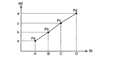
The gas chromatograph apparatus according to the above Reference Example, two compounds alpha, created a conversion formula between retention index and the retention time as a result of analyzing the using (3) for β, but the compound to be analyzed The accuracy of the conversion formula can be increased by increasing the number of types. For example, when GC analysis is performed on four types of compounds α, β, γ, and δ whose retention indices are known, and a chromatogram as shown in FIG. 5 is obtained, retention time (RT) and retention index (RI) The combinations (RT, RI) are (a, A), (b, B), (c, C), and (d, D).
この4種の化合物α、β、γ、δについての上記分析結果による(RT,RI)を、横軸に保持指標、縦軸に保持時間をとったグラフ上にプロットすると図6中の点Pa、Pb、Pc、Pdに示すようになる。そこで、隣接する2点間を直線的に内挿するような線を描き、この線を表す換算式を作成するものとする。
すると、A〜B区間では、
RT=[(b−a)/(B−A)]×(RI−A)+a …(4)
B〜C区間では、
RT=[(c−b)/(C−B)]×(RI−B)+b …(5)
C〜D区間では、
RT=[(d−c)/(D−C)]×(RI−C)+c …(6)
と換算式が求まる。なお、A以下の区間では(4)式で決まる線を点Paの外側にそのまま外挿し、D以上の区間では(6)式で決まる線を点Pdの外側にそのまま外挿すればよい。
When the (RT, RI) based on the above analysis results for these four types of compounds α, β, γ, and δ are plotted on a graph with the horizontal axis representing the retention index and the vertical axis representing the retention time, point Pa in FIG. , Pb, Pc, Pd. Therefore, a line that linearly interpolates between two adjacent points is drawn, and a conversion formula representing this line is created.
Then, in the A to B section,
RT = [(ba) / (BA)] * (RI-A) + a (4)
In the B-C section,
RT = [(c−b) / (C−B)] × (RI−B) + b (5)
In section C to D,
RT = [(dc) / (DC)] * (RI-C) + c (6)
And the conversion formula is obtained. In the section below A, the line determined by equation (4) is extrapolated outside the point Pa, and in the section above D, the line determined by equation (6) is extrapolated as it is outside the point Pd.
上記換算式によれば、上記参考例の場合よりも保持指標から保持時間を推定する精度が向上するためピーク同定の正確性を高めることができ、ピークの誤同定や見逃しを軽減することができる。もちろん、上記のような直線的な内挿補間を行った換算式ではなく、n次多項式が上記各点を通過するとして係数を算出し、この多項式を換算式としてもよい。
According to the above conversion formula, the accuracy of estimating the retention time from the retention index is improved as compared with the case of the above reference example, so that the accuracy of peak identification can be improved, and erroneous identification or oversight of peaks can be reduced. . Of course, instead of the conversion formula obtained by performing the linear interpolation as described above, the coefficient may be calculated on the assumption that the nth order polynomial passes through each point, and this polynomial may be used as the conversion formula.
[実施例]
上記参考例では、保持指標データベース13に収録されている任意の複数の化合物の保持時間を測定し、その保持時間と保持指標との関係から分析対象である化合物の保持時間を推定していたが、本発明に係る実施例では、この保持指標の基準物質であるn−アルカンの保持時間を推算し、そのn−アルカンの保持時間と分析対象化合物の保持指標とからその保持時間を推定する。こうした処理動作を行う実施例によるガスクロマトグラフ装置について、次に説明する。
[ Example]
In the above reference example, the retention times of any of a plurality of compounds recorded in the
この実施例によるガスクロマトグラフ装置の基本的な構成は上記参考例と同じであり、データ処理部10におけるピーク同定処理方法が異なるだけであるので構成についての説明は省略する。
The basic configuration of a gas chromatograph apparatus according to this embodiment is the same as the reference example, description of the structure since the peak identification processing method in the
まず制御部7の制御の下に、保持指標データベースに収録されている、n−アルカンを基準とする保持指標が既知である3種の化合物α、β、γについて、所定の分析条件(ここでは昇温分析とする)で以てGC分析を実行する。ここで、化合物α、β、γは、保持指標の基準物質であるn−アルカンCn、Cn+1、Cn+2に対し次のような条件を満たすものを選択する。
Cn <RI(α)、RI(β)<Cn+1 但しRI(α)≠RI(β)
Cn+1 <RI(γ)<Cn+2
上記分析により、図7に示すようなクロマトグラムを取得し、各化合物α、β、γの保持時間(RT)a、b、cを求める。化合物α、β、γの保持時間(RT)と保持指標(RI)との組み合わせ(RT,RI)は、(a,A)、(b,B)、(c,C)となる。
First, under the control of the
C n <RI (α), RI (β) <C n + 1 where RI (α) ≠ RI (β)
C n + 1 <RI (γ) <C n + 2
By the above analysis, a chromatogram as shown in FIG. 7 is obtained, and retention times (RT) a, b, and c of the respective compounds α, β, and γ are obtained. The combinations (RT, RI) of the retention times (RT) and retention indices (RI) of the compounds α, β, γ are (a, A), (b, B), (c, C).
次に、化合物α、βの保持時間と保持指標、つまり(a,A)、(b,B)より、Cn、Cn+1の保持時間を推算する。昇温分析においては(2)式より、
RI={[RT−RT(Cn)]/[RT(Cn+1)−RT(Cn)]}×100+100×n …(7)
となり、これを変形すると、
(RI−100×n)×RT(Cn+1)+(100×n+100−RI)×RT(Cn)=RT …(8)
となる。この(8)式に化合物α、βのRI、RTを代入し、式を解くことによりRT(Cn)、RT(Cn+1)が求まる。
Next, the retention times of C n and C n + 1 are estimated from the retention times and retention indices of the compounds α and β, that is, (a, A) and (b, B). In temperature rising analysis, from equation (2):
RI = {[RT−RT (C n )] / [RT (C n + 1 ) −RT (C n )]} × 100 + 100 × n (7)
And when this is transformed,
(RI-100 × n) × RT (C n + 1) + (100 × n + 100-RI) × RT (C n) = RT ... (8)
It becomes. By substituting RI and RT of the compounds α and β into the equation (8) and solving the equation, RT (C n ) and RT (C n + 1 ) are obtained.
また、Cn+1とCn+2の保持時間についても(8)式と同様の式を求めることができ、化合物γの保持時間と保持指標とが既知であるとともに、上記計算よりCn+1の保持時間RT(Cn+1)も得られているから、これらを式に代入することによりCn+2の保持時間が求まる。さらにn+3以上のn−アルカンの保持時間が必要な場合には、上記と同様の処理を繰り返すことで保持時間を推算することができる。 Further, the retention times of C n + 1 and C n + 2 can be obtained by the same equation as the equation (8), and the retention time and retention index of compound γ are known, and the retention time RT of C n + 1 is known from the above calculation. Since (C n + 1 ) is also obtained, the retention time of C n + 2 is obtained by substituting these into the equation. Furthermore, when the retention time of n + alkane of n + 3 or more is required, the retention time can be estimated by repeating the same process as described above.
その後、上記のように推算されたn−アルカンの保持時間と分析対象化合物の保持指標とから、(8)式によりその分析対象化合物の保持時間を推算することができる。分析対象化合物の保持時間が求まったならば、上記参考例と同様にこれを利用して、試料をクロマトグラフ分析することにより得られたクロマトグラフに現れているピークを同定する。これによって、参考例と同様に、任意の分析対象化合物を同定することが可能となる。
Thereafter, from the n-alkane retention time estimated as described above and the retention index of the analysis target compound, the retention time of the analysis target compound can be estimated by the equation (8). When the retention time of the analysis target compound is obtained, the peak appearing in the chromatograph obtained by chromatographic analysis of the sample is identified using this as in the above Reference Example . This makes it possible to identify any analysis target compound as in the reference example .
[実施例の変形例]
また上記実施例によるガスクロマトグラフ装置の変形例によるデータ処理として次のようにしてもよい。即ち、制御部7の制御の下に、保持指標データベースに収録されている、n−アルカンを基準とする保持指標が既知である3種の化合物α、β、γについて、所定の分析条件(ここでは昇温分析とする)で以てGC分析を実行する。ここで、化合物α、β、γは、保持指標の基準物質であるn−アルカンCn、Cn+1に対し次のような条件を満たすものを選択する。
RI(α)<Cn <RI(β)
Cn+1 <RI(γ)<Cn+2
上記分析により、図8に示すようなクロマトグラムを取得し、上記実施例2と同様に、化合物α、β、γの保持時間(RT)と保持指標(RI)との組み合わせ(a,A)、(b,B)、(c,C)を取得する。
[Modification Example]
Or it may be as follows as a data processing according to the modification of the gas chromatograph apparatus according to the aforementioned embodiments. That is, under the control of the
RI (α) <C n <RI (β)
C n + 1 <RI (γ) <C n + 2
By the above analysis, a chromatogram as shown in FIG. 8 is obtained, and the combination (a, A) of the retention time (RT) and retention index (RI) of the compounds α, β, γ as in Example 2 above. , (B, B), (c, C) are acquired.
次に、化合物α、βの保持時間と保持指標、つまり(a,A)、(b,B)より、Cn、Cn+1の保持時間を推算する。Cnの保持時間RT(Cn)は次の(9)式となる。
RT(Cn)=[(b−a)/(B−A)]×[RI(Cn)−A]+a …(9)
即ち、この(9)式は、図9に示すように横軸を保持指標、縦軸を保持時間としたグラフにおいて2点(a,A)、(b,B)を直線的に内挿補間した線を表す式となる。また同様にして、Cn+1の保持時間も求めることができる。それ以降は、上記実施例と同様である。
Next, the retention times of C n and C n + 1 are estimated from the retention times and retention indices of the compounds α and β, that is, (a, A) and (b, B). C n retention time RT (C n) is represented by the following equation (9).
RT (C n ) = [(b−a) / (BA)] × [RI (C n ) −A] + a (9)
That is, the equation (9) is obtained by linearly interpolating two points (a, A) and (b, B) in a graph in which the horizontal axis is the holding index and the vertical axis is the holding time as shown in FIG. This is the expression that represents the line. Similarly, the holding time of C n + 1 can be obtained. Thereafter is the same as the above embodiment.
なお、昇温分析においては、メチレンユニット当たりのエントロピーがほぼ等しいので、1メチレンユニット間隔の保持時間はほぼ等しくなる。したがって、例えば化合物αの保持指標Aと化合物βの保持指標Bとの間に複数のn−アルカンCn、Cn+1、…が含まれていても、これらCn、Cn+1、…を推測することが可能である。 In the temperature rising analysis, since the entropy per methylene unit is substantially equal, the retention time of one methylene unit interval is substantially equal. Therefore, for example, even when a plurality of n-alkanes C n , C n + 1 ,... Are included between the retention index A of the compound α and the retention index B of the compound β, these C n , C n + 1 ,. It is possible.
また、参考例でも同様であるが、昇温分析のときには保持時間と保持指標との関係がほぼ直線的になるため、例えば(9)式のような換算式を用いた推定値の精度が高い。これに対し、昇温分析ではなく恒温分析の場合には、(1)式と(2)式との比較でも分かるように対数log分だけのずれが生じることになる。しかしながら、分析条件によってはあまり大きな差とはならないので、恒温分析においても上記のような換算が適用可能な場合がある。
As in the reference example, since the relationship between the retention time and the retention index becomes almost linear during the temperature rise analysis, the accuracy of the estimated value using a conversion equation such as the equation (9) is improved. high. On the other hand, in the case of constant temperature analysis instead of temperature rise analysis, a shift of logarithm log occurs as can be seen from comparison between the equations (1) and (2). However, since the difference is not so large depending on the analysis conditions, the above-mentioned conversion may be applicable even in the constant temperature analysis.
なお、上記実施例は本発明の一例にすぎず、本発明の趣旨に沿った範囲で適宜変形や修正を行うことができることは明らかである。例えば、本発明において検出器としては様々なものを利用できるから、例えばガスクロマトグラフと質量分析装置とを組み合わせたガスクロマトグラフ質量分析装置にも適用することができる。ガスクロマトグラフ質量分析装置の場合、トータルイオンクロマトグラムや特定の質量数に着目したマスクロマトグラムに出現しているピークを保持時間に基づいて同定するとともに、マススペクトルに現れるピークによる同定も行い、両者の同定結果を併せて最終的に正確な成分同定を行うような処理が行われる場合があるが、こうした処理に際しても本発明のようなデータ処理を適用して同様の効果を奏することは容易に想到し得る。 It should be noted that the above embodiment is merely an example of the present invention, and it is apparent that modifications and corrections can be made as appropriate within the scope of the present invention. For example, since various detectors can be used in the present invention, for example, the present invention can be applied to a gas chromatograph mass spectrometer combining a gas chromatograph and a mass spectrometer. In the case of a gas chromatograph mass spectrometer, the peaks appearing in the total ion chromatogram and the mass chromatogram focusing on a specific mass number are identified based on the retention time, and the peaks appearing in the mass spectrum are also identified. In some cases, a process for finally identifying the correct component is performed together with the identification results, but it is easy to apply the data processing as in the present invention to achieve the same effect even in such a process. I can think of it.
1…インジェクタ
2…試料気化室
3…キャリアガス導入管
4…カラムオーブン
5…カラム
6…検出器
7…制御部
8…入力部
9…表示部
10…データ処理部
11…ピーク同定処理部
12…保持時間推定部
13…保持指標データベース
DESCRIPTION OF
Claims (2)
b)前記複数の化合物の保持時間とその各物質の既知の保持指標との関係に基づいて、前記基準物質の保持時間を推定する第1保持時間推定手段と、
c)該第1保持時間推定手段により得られる前記基準物質の保持時間と分析対象化合物の既知の保持指標とから、該分析対象化合物の保持時間を推定する第2保持時間推定手段と、
d)該第2保持時間推定手段により推定された保持時間を用いて、前記分析対象化合物を含む試料をガスクロマトグラフ分析して作成したクロマトグラムに現れているピークを同定する同定処理手段と、
を備えることを特徴とするガスクロマトグラフ装置。 a) an analysis execution means for performing a gas chromatographic analysis on a plurality of compounds having a known retention index based on a predetermined reference substance and obtaining a retention time of each compound;
b) first retention time estimation means for estimating the retention time of the reference substance based on the relationship between the retention times of the plurality of compounds and the known retention index of each substance;
c) second retention time estimation means for estimating the retention time of the analyte compound from the retention time of the reference substance obtained by the first retention time estimation means and the known retention index of the analyte compound;
d) an identification processing means for identifying a peak appearing in a chromatogram created by gas chromatographic analysis of a sample containing the analysis target compound using the retention time estimated by the second retention time estimation means;
A gas chromatograph apparatus comprising:
Priority Applications (1)
| Application Number | Priority Date | Filing Date | Title |
|---|---|---|---|
| JP2005116562A JP4507962B2 (en) | 2005-04-14 | 2005-04-14 | Gas chromatograph |
Applications Claiming Priority (1)
| Application Number | Priority Date | Filing Date | Title |
|---|---|---|---|
| JP2005116562A JP4507962B2 (en) | 2005-04-14 | 2005-04-14 | Gas chromatograph |
Publications (3)
| Publication Number | Publication Date |
|---|---|
| JP2006292652A JP2006292652A (en) | 2006-10-26 |
| JP2006292652A5 JP2006292652A5 (en) | 2007-07-26 |
| JP4507962B2 true JP4507962B2 (en) | 2010-07-21 |
Family
ID=37413361
Family Applications (1)
| Application Number | Title | Priority Date | Filing Date |
|---|---|---|---|
| JP2005116562A Active JP4507962B2 (en) | 2005-04-14 | 2005-04-14 | Gas chromatograph |
Country Status (1)
| Country | Link |
|---|---|
| JP (1) | JP4507962B2 (en) |
Families Citing this family (5)
| Publication number | Priority date | Publication date | Assignee | Title |
|---|---|---|---|---|
| US8134121B2 (en) * | 2006-10-31 | 2012-03-13 | Shimadzu Corporation | Chromatographic mass spectrometer |
| JP6067549B2 (en) * | 2011-03-02 | 2017-01-25 | 株式会社堀場エステック | Data processing apparatus for gas chromatograph and data processing program used therefor |
| JP6064359B2 (en) * | 2012-04-10 | 2017-01-25 | 富士通株式会社 | Environmental load evaluation device, environmental load evaluation method and program |
| KR20190098601A (en) * | 2018-02-14 | 2019-08-22 | (주)바이오니아 | Method of analyzing gas samples and analyzing apparatus thereof |
| CN117434186A (en) * | 2023-12-22 | 2024-01-23 | 中国市政工程华北设计研究总院有限公司 | Synchronous identification and quantification method for complex odor gas composition of sewage-carrying rainwater |
Citations (8)
| Publication number | Priority date | Publication date | Assignee | Title |
|---|---|---|---|---|
| JPS63204146A (en) * | 1987-02-19 | 1988-08-23 | Shimadzu Corp | Qualitative analysis for gas chromatography mass spectrometer |
| JPH03142358A (en) * | 1989-10-30 | 1991-06-18 | Ogawa Koryo Kk | Quantitative analysis by using gc/ms |
| JPH11153587A (en) * | 1997-11-19 | 1999-06-08 | Mitsubishi Chemical Corp | Component determining method in chromatography |
| JPH11201960A (en) * | 1998-01-08 | 1999-07-30 | Shimadzu Corp | Gas chromatograph |
| JP2003139755A (en) * | 2001-11-05 | 2003-05-14 | Kitakyushu Foundation For The Advancement Of Industry Science & Technology | Method for simultaneous identification and quantitative determination for widely used multi-component in chromatograph/mass spectrograph |
| JP2006284371A (en) * | 2005-03-31 | 2006-10-19 | Shimadzu Corp | Method of analyzing mass |
| JP2006292446A (en) * | 2005-04-07 | 2006-10-26 | Shimadzu Corp | Gas chromatograph device |
| JP2006292613A (en) * | 2005-04-13 | 2006-10-26 | Shimadzu Corp | Gas chromatograph device, and data processing method of the same |
-
2005
- 2005-04-14 JP JP2005116562A patent/JP4507962B2/en active Active
Patent Citations (8)
| Publication number | Priority date | Publication date | Assignee | Title |
|---|---|---|---|---|
| JPS63204146A (en) * | 1987-02-19 | 1988-08-23 | Shimadzu Corp | Qualitative analysis for gas chromatography mass spectrometer |
| JPH03142358A (en) * | 1989-10-30 | 1991-06-18 | Ogawa Koryo Kk | Quantitative analysis by using gc/ms |
| JPH11153587A (en) * | 1997-11-19 | 1999-06-08 | Mitsubishi Chemical Corp | Component determining method in chromatography |
| JPH11201960A (en) * | 1998-01-08 | 1999-07-30 | Shimadzu Corp | Gas chromatograph |
| JP2003139755A (en) * | 2001-11-05 | 2003-05-14 | Kitakyushu Foundation For The Advancement Of Industry Science & Technology | Method for simultaneous identification and quantitative determination for widely used multi-component in chromatograph/mass spectrograph |
| JP2006284371A (en) * | 2005-03-31 | 2006-10-19 | Shimadzu Corp | Method of analyzing mass |
| JP2006292446A (en) * | 2005-04-07 | 2006-10-26 | Shimadzu Corp | Gas chromatograph device |
| JP2006292613A (en) * | 2005-04-13 | 2006-10-26 | Shimadzu Corp | Gas chromatograph device, and data processing method of the same |
Also Published As
| Publication number | Publication date |
|---|---|
| JP2006292652A (en) | 2006-10-26 |
Similar Documents
| Publication | Publication Date | Title |
|---|---|---|
| JP6494588B2 (en) | Use of windowed mass spectrometry data to determine or confirm residence time | |
| US10121643B2 (en) | Chromatography/mass spectrometry data processing device | |
| JP4973628B2 (en) | Chromatograph mass spectrometry data analysis method and apparatus | |
| EP1995593B1 (en) | Chromatograph mass spectrometer | |
| JP5347932B2 (en) | Chromatograph mass spectrometer | |
| JP5262482B2 (en) | Gas chromatograph | |
| JP4507962B2 (en) | Gas chromatograph | |
| WO2018087824A1 (en) | Data analysis apparatus for chromatography mass spectrometry | |
| US11567047B2 (en) | Chromatographic data system processing apparatus | |
| WO2014064790A1 (en) | Data processing device for comprehensive two-dimensional chromatograph | |
| JP2013195099A (en) | Chromatograph mass spectrometry data processing device | |
| JP2006292446A (en) | Gas chromatograph device | |
| JP4595825B2 (en) | Data processor for automatic analysis | |
| WO2015198385A1 (en) | Data processing device for comprehensive two-dimensional chromatography | |
| JP4438674B2 (en) | Gas chromatograph apparatus and data processing method of the apparatus | |
| JP4470811B2 (en) | Chromatographic analyzer | |
| JP6743972B2 (en) | Sample analyzer | |
| US20150168360A1 (en) | Chromatogram display method, chromatogram display device, and chromatograph comprising said device | |
| JP2005321200A (en) | Data control device for instrumental analysis | |
| JPWO2020110864A1 (en) | Analytical methods and programs | |
| JP4009737B2 (en) | Chromatogram analyzer | |
| JP6123300B2 (en) | Chromatographic data processor | |
| Lebrón-Aguilar et al. | Improving the accuracy of Kováts’ retention indices in isothermal gas chromatography | |
| Dettmer-Wilde et al. | Quantitative analysis | |
| EP2793020A1 (en) | Data processing device for gas chromatograph, data processing method, and data processing program |
Legal Events
| Date | Code | Title | Description |
|---|---|---|---|
| A521 | Written amendment |
Free format text: JAPANESE INTERMEDIATE CODE: A523 Effective date: 20070611 |
|
| A621 | Written request for application examination |
Free format text: JAPANESE INTERMEDIATE CODE: A621 Effective date: 20070611 |
|
| A977 | Report on retrieval |
Free format text: JAPANESE INTERMEDIATE CODE: A971007 Effective date: 20091207 |
|
| A131 | Notification of reasons for refusal |
Free format text: JAPANESE INTERMEDIATE CODE: A131 Effective date: 20100209 |
|
| A521 | Written amendment |
Free format text: JAPANESE INTERMEDIATE CODE: A523 Effective date: 20100312 |
|
| RD02 | Notification of acceptance of power of attorney |
Free format text: JAPANESE INTERMEDIATE CODE: A7422 Effective date: 20100312 |
|
| TRDD | Decision of grant or rejection written | ||
| A01 | Written decision to grant a patent or to grant a registration (utility model) |
Free format text: JAPANESE INTERMEDIATE CODE: A01 Effective date: 20100413 |
|
| A01 | Written decision to grant a patent or to grant a registration (utility model) |
Free format text: JAPANESE INTERMEDIATE CODE: A01 |
|
| A61 | First payment of annual fees (during grant procedure) |
Free format text: JAPANESE INTERMEDIATE CODE: A61 Effective date: 20100426 |
|
| FPAY | Renewal fee payment (event date is renewal date of database) |
Free format text: PAYMENT UNTIL: 20130514 Year of fee payment: 3 |
|
| R151 | Written notification of patent or utility model registration |
Ref document number: 4507962 Country of ref document: JP Free format text: JAPANESE INTERMEDIATE CODE: R151 |
|
| FPAY | Renewal fee payment (event date is renewal date of database) |
Free format text: PAYMENT UNTIL: 20130514 Year of fee payment: 3 |
|
| FPAY | Renewal fee payment (event date is renewal date of database) |
Free format text: PAYMENT UNTIL: 20130514 Year of fee payment: 3 |
|
| FPAY | Renewal fee payment (event date is renewal date of database) |
Free format text: PAYMENT UNTIL: 20140514 Year of fee payment: 4 |