JP4507616B2 - Projection type display device, image output device, and control method for projection type display device - Google Patents
Projection type display device, image output device, and control method for projection type display device Download PDFInfo
- Publication number
- JP4507616B2 JP4507616B2 JP2004028043A JP2004028043A JP4507616B2 JP 4507616 B2 JP4507616 B2 JP 4507616B2 JP 2004028043 A JP2004028043 A JP 2004028043A JP 2004028043 A JP2004028043 A JP 2004028043A JP 4507616 B2 JP4507616 B2 JP 4507616B2
- Authority
- JP
- Japan
- Prior art keywords
- light
- display device
- modulated
- projection
- unit
- Prior art date
- Legal status (The legal status is an assumption and is not a legal conclusion. Google has not performed a legal analysis and makes no representation as to the accuracy of the status listed.)
- Expired - Fee Related
Links
Images


Description
本発明は、投射型表示装置および投射型表示装置の制御方法に関する。 The present invention relates to a projection display device and a control method for the projection display device.
光変調デバイスとして液晶表示装置(LCD)や、例えばTI(テキサスインスツルメンツ)社のDMD(デジタルマイクロミラーデバイス、登録商標)素子などのミラーデバイスなどを用いた投射型表示装置(プロジェクタ)が知られ、オフィスでのデータプロジェクタ、家庭でのビデオプロジェクタとして広く使用されている。
従来の投射型表示装置における投射画像のダイナミックレンジは、投射型表示装置の最大出力と最低出力で決まり、映像の中における1部のシーンや、1フレームでのダイナミックレンジは、画素値の最大値と最小値に応じた投射型表示装置からの出力値で決まっている(例えば、非特許文献1参照。)。
The dynamic range of the projected image in the conventional projection display device is determined by the maximum output and the minimum output of the projection display device, and the dynamic range in one scene or one frame in the video is the maximum pixel value. And the output value from the projection type display device corresponding to the minimum value (for example, see Non-Patent Document 1).
そのため、表示する画像(シーン)によっては、画像の暗い部分や明るい部分においてダイナミックレンジの不足により不鮮明となりやすいという問題があった。 For this reason, depending on the image (scene) to be displayed, there is a problem that the dark portion or the bright portion of the image tends to become unclear due to the lack of the dynamic range.
本発明は、上記の課題を解決するためになされたものであって、投射画像のダイナミックレンジを増加させ、投射画像の画質を高めることができる投射型表示装置およびその制御方法を提供することを目的とする。 The present invention has been made to solve the above-described problems, and provides a projection display device that can increase the dynamic range of a projected image and enhance the image quality of the projected image, and a control method thereof. Objective.
上記目的を達成するために、本発明の投射型表示装置は、光を射出する第1の光源と、第1の光源からの光を変調する第1の光変調手段と、光を射出する第2の光源と、第1の光変調手段により変調された光および第2の光源からの光を重畳させる光合成手段と、重畳された光を投射する投射手段と、を有し、第2の光源から射出された光が、投射する画像に応じて変調されることを特徴とする。 In order to achieve the above object, a projection display device according to the present invention includes a first light source that emits light, a first light modulation unit that modulates light from the first light source, and a first light source that emits light. A second light source, a light combining unit that superimposes the light modulated by the first light modulation unit and the light from the second light source, and a projection unit that projects the superimposed light. The light emitted from is modulated in accordance with the image to be projected.
すなわち、本発明の投射型表示装置は、第1の光変調手段により変調された画像を表す光に画像に応じて変調された第2の光源からの光を重畳させて画像を表示しているため、第1の光変調手段により変調された光のみで表示される画像のダイナミックレンジと比較して、当該投射型表示装置により投射される画像のダイナミックレンジを拡大させることができ、投射画像の画質を高めることができる。
つまり、第1の光変調手段により変調された光のみで表示される画像の上に、画像に応じて変調された第2の光源からの光を重畳させることにより、ダイナミックレンジの上限を拡大し、より広いダイナミックレンジでの画像表示を可能としている。
That is, the projection display device of the present invention displays an image by superimposing light from the second light source modulated according to the image on the light representing the image modulated by the first light modulation means. Therefore, compared with the dynamic range of the image displayed only with the light modulated by the first light modulation means, the dynamic range of the image projected by the projection display device can be expanded, The image quality can be improved.
In other words, the upper limit of the dynamic range is expanded by superimposing the light from the second light source modulated according to the image on the image displayed only with the light modulated by the first light modulation means. This enables image display with a wider dynamic range.
上記の構成を実現するために、より具体的には、第2の光源と光合成手段との間には、第2の光源から射出された光を変調する第2の光変調手段が配置されていることが望ましい。
この構成によれば、第2の光変調手段により第2の光源から射出された光を変調しているため、投射画像の細かい領域(例えば画素)単位でダイナミックレンジを拡大させることができる。そのため、同じ投射画像の中に明るさが大きく異なる領域が存在しても、明るい領域のダイナミックレンジを拡大させることができるため、明るい領域および暗い領域の画像が不鮮明になることを防止することができる。
In order to realize the above configuration, more specifically, a second light modulation unit that modulates the light emitted from the second light source is arranged between the second light source and the light combining unit. It is desirable.
According to this configuration, since the light emitted from the second light source is modulated by the second light modulation unit, the dynamic range can be expanded in units of fine regions (for example, pixels) of the projection image. Therefore, even if there are areas with significantly different brightness in the same projected image, the dynamic range of the bright area can be expanded, so that the image of the bright area and the dark area can be prevented from becoming unclear. it can.
上記の構成を実現するために、より具体的には、第1の光変調手段に形成された画素数と、第2の光変調手段に形成された画素数とが同じであってもよい。
この構成によれば、第1の光変調手段および第2の光変調手段における画素の数が同じであるため、投射される画像のダイナミックレンジを投射画像の画素ごとに柔軟に制御することができる。
つまり、第1の光変調手段の画素と第2の光変調手段の画素とが1対1に対応しているため、投射される画像の各画素について、第1の光変調手段の画素および第2の光変調手段の画素が対応することになる。その結果、画像の各画素において第1の光変調手段により変調された光と第2の光変調手段により変調された光とが重畳されるため、投射される画像のダイナミックレンジを画素ごとに柔軟に制御することができる。
In order to realize the above configuration, more specifically, the number of pixels formed in the first light modulation unit and the number of pixels formed in the second light modulation unit may be the same.
According to this configuration, since the number of pixels in the first light modulation unit and the second light modulation unit is the same, the dynamic range of the projected image can be flexibly controlled for each pixel of the projection image. .
That is, since the pixels of the first light modulator and the pixels of the second light modulator have a one-to-one correspondence, for each pixel of the projected image, the first light modulator and the first light modulator The pixels of the second light modulation means correspond to each other. As a result, the light modulated by the first light modulation means and the light modulated by the second light modulation means are superimposed on each pixel of the image, so that the dynamic range of the projected image can be flexibly changed for each pixel. Can be controlled.
上記の構成を実現するために、より具体的には、第1の光変調手段に形成された画素数よりも、第2の光変調手段に形成された画素数が多くてもよい。
この構成によれば、投射される画像のダイナミックレンジの制御は、第2の光変調手段に形成された画素に対応する画素ごとに行うことができる。例えば、第1の光変調手段に形成された1つの画素により変調された光の照明領域上に、第2の光変調手段に形成された複数の画素より変調された光が重畳されるため、投射される画像のダイナミックレンジ制御可能な領域は、第2の光変調手段に形成された画素により規定される。
In order to realize the above configuration, more specifically, the number of pixels formed in the second light modulation unit may be larger than the number of pixels formed in the first light modulation unit.
According to this configuration, the dynamic range of the projected image can be controlled for each pixel corresponding to the pixel formed in the second light modulation unit. For example, light modulated by a plurality of pixels formed on the second light modulation unit is superimposed on an illumination area of light modulated by one pixel formed on the first light modulation unit. The region in which the dynamic range of the projected image can be controlled is defined by the pixels formed in the second light modulation unit.
上記の構成を実現するために、より具体的には、第1の光変調手段に形成された画素数よりも、第2の光変調手段に形成された画素数が少なくてもよい。
この構成によれば、例えば、第1の光変調手段に形成された複数の画素により変調された光の複数の照明領域上に、第2の光変調手段に形成された1つの画素により変調された光を重畳させて、投射される画像のダイナミックレンジの制御を行うことができる。
そのため、例えば第2の光変調手段としてミラーデバイスを用いる場合、投射画像の画素よりも大きなマイクロミラーを用いることができ、比較的安価で製造容易なミラーデバイスを用いることができる。
In order to realize the above configuration, more specifically, the number of pixels formed in the second light modulation unit may be smaller than the number of pixels formed in the first light modulation unit.
According to this configuration, for example, the light is modulated by one pixel formed in the second light modulation unit on the plurality of illumination regions of the light modulated by the plurality of pixels formed in the first light modulation unit. The dynamic range of the projected image can be controlled by superimposing the reflected light.
Therefore, for example, when a mirror device is used as the second light modulation means, a micromirror larger than the pixel of the projected image can be used, and a mirror device that is relatively inexpensive and easy to manufacture can be used.
上記の構成を実現するために、より具体的には、第2の光変調手段が、入射した光の射出方向を制御することにより、入射した光を時間変調するミラーデバイスであることが望ましい。
この構成によれば、第2の光変調手段がミラーデバイスであるため、入射光の射出方向をミラーで制御することで光の変調を行うことができる。ミラーデバイスは、例えば液晶パネルを比較すると、光の変調効率が高く(液晶パネルは所定の直線偏光しか変調できない)、光源から発生する熱に対しても劣化し難い(液晶は高熱に弱い)特性を有する。そのため、ミラーデバイスを用いることにより、強い光を射出する光源を用いることができるとともに、光源から射出された光の利用効率を向上させることができる。
More specifically, in order to realize the above-described configuration, it is desirable that the second light modulation unit is a mirror device that time-modulates the incident light by controlling the emission direction of the incident light.
According to this configuration, since the second light modulation means is a mirror device, the light can be modulated by controlling the emission direction of the incident light with the mirror. Mirror devices, for example, have higher light modulation efficiency than liquid crystal panels (liquid crystal panels can only modulate predetermined linearly polarized light) and are less susceptible to heat generated from light sources (liquid crystals are vulnerable to high heat). Have Therefore, by using a mirror device, a light source that emits strong light can be used, and the utilization efficiency of light emitted from the light source can be improved.
上記の構成を実現するために、より具体的には、第2の光変調手段によるダイナミックレンジの拡大を、投射画像の1フレームごとに決定してもよい。
この構成によれば、1フレームごとにダイナミックレンジの拡大を決定しているため、複数フレームごとにダイナミックレンジの拡大を決定する場合と比較して、ダイナミックレンジの拡大を決定する回路構成を簡略化することができる。また、ダイナミックレンジの拡大を決定する演算アルゴリズムを簡略化することができる。
例えば、複数フレーム分のデータを一時保存する記憶部を回路構成に追加する必要がない分、回路構成を簡略化することができる。また、複数フレームにわたって階調の整合性を取る演算を行う必要がない分、演算アルゴリズムを簡略化することができる。
In order to realize the above configuration, more specifically, expansion of the dynamic range by the second light modulation unit may be determined for each frame of the projection image.
According to this configuration, since the expansion of the dynamic range is determined for each frame, the circuit configuration for determining the expansion of the dynamic range is simplified compared to the case where the expansion of the dynamic range is determined for each frame. can do. In addition, it is possible to simplify the arithmetic algorithm for determining the expansion of the dynamic range.
For example, the circuit configuration can be simplified because it is not necessary to add a storage unit for temporarily storing data for a plurality of frames to the circuit configuration. Further, the calculation algorithm can be simplified because it is not necessary to perform an operation for obtaining gradation consistency over a plurality of frames.
上記の構成を実現するために、より具体的には、第2の光変調手段によるダイナミックレンジの拡大を、投射画像の複数フレームごとに決定してもよい。
この構成によれば、複数フレームごとにダイナミックレンジの拡大を決定しているため、1フレームごとにダイナミックレンジの拡大を決定する場合と比較して、連続するフレーム間における画像の輝度の連続性がよくなる。
つまり、1フレームごとにダイナミックレンジの拡大を決定している場合、連続するフレームにおける同一の画素の輝度は、連続して変化しない(急に明るくなったり暗くなったりする)恐れがあるが、複数フレームごとにダイナミックレンジの拡大を決定することにより、前述のような不具合の発生を確実に防止することができる。
In order to realize the above configuration, more specifically, expansion of the dynamic range by the second light modulation unit may be determined for each of a plurality of frames of the projection image.
According to this configuration, since the expansion of the dynamic range is determined for each of a plurality of frames, the continuity of the luminance of the image between consecutive frames is higher than when the expansion of the dynamic range is determined for each frame. Get better.
In other words, if the expansion of the dynamic range is determined for each frame, the brightness of the same pixel in successive frames may not change continuously (it will suddenly become brighter or darker). By determining the expansion of the dynamic range for each frame, it is possible to reliably prevent the occurrence of the above-described problems.
上記の構成を実現するために、より具体的には、第2の光変調手段への制御信号の生成を、当該装置内で行ってもよい。
この構成によれば、当該投射型表示装置内で制御信号の生成を行うため、画像情報のみを有する映像信号を入力するだけでダイナミックレンジの拡大された画像を投射することができる。つまり、当該投射型表示装置に、通常のTV信号、ビデオ信号などを入力することにより、ダイナミックレンジの拡大されたTV画像や、ビデオ画像を容易に投射することができる。
また、当該投射型表示装置の外に制御信号の生成を行う機器を備える場合と比べ、当該投射型表示装置のみでダイナミックレンジが拡大された画像を投射できるため、持ち運び性に優れ、設置場所を必要としないといった優れた点を有する。
In order to realize the above configuration, more specifically, the generation of the control signal to the second optical modulation unit may be performed in the apparatus.
According to this configuration, since the control signal is generated in the projection display device, an image with an expanded dynamic range can be projected only by inputting a video signal having only image information. That is, by inputting a normal TV signal, a video signal, or the like to the projection display device, a TV image or a video image with an expanded dynamic range can be easily projected.
Compared with the case where a device for generating a control signal is provided outside the projection type display device, an image with an expanded dynamic range can be projected only by the projection type display device. It has the advantage that it is not necessary.
上記の構成を実現するために、より具体的には、第2の光変調手段への制御信号の生成を、当該装置外の画像出力機器内で行ってもよい。
この構成によれば、当該投射型表示装置外の画像出力機器に画像情報のみを有する映像信号を入力して制御信号の生成を行っているため、当該投射型表示装置内で制御信号の生成を行っている場合と比較して、より細かくダイナミックレンジが拡大された画像を投射することができる。つまり、投射型表示装置よりもスペースの制約が少ない外部の画像出力機器で制御信号の生成を行うため、より複雑、大型な回路を用いることができ、それにより複雑な演算アルゴリズムによるきめ細かな制御を行うことができる。
In order to realize the above configuration, more specifically, the generation of the control signal to the second light modulation unit may be performed in an image output device outside the apparatus.
According to this configuration, since the control signal is generated by inputting the video signal having only the image information to the image output device outside the projection display device, the control signal is generated in the projection display device. Compared with the case where it is performed, the image where the dynamic range was expanded more finely can be projected. In other words, the control signal is generated by an external image output device that has less space restrictions than the projection display device, so that a more complicated and large circuit can be used, thereby enabling fine control by a complicated arithmetic algorithm. It can be carried out.
上記の構成を実現するために、より具体的には、周囲の環境光を検出する光検出手段を備え、光検出手段の出力に応じて、ダイナミックレンジの拡大を決定してもよい。
この構成によれば、環境の明るさに応じてダイナミックレンジの拡大を決定するため、明るい環境の時にはダイナミックレンジをより明るく拡大させ、暗い環境の時にはダイナミックレンジの拡大を抑制することができる。そのため、当該投射型表示装置は周囲の明るさに対して、明るすぎず暗すぎない画像を投射することができ、視聴者に対して見やすい画像を投射することができる。
In order to realize the above configuration, more specifically, a light detection unit that detects ambient ambient light may be provided, and the expansion of the dynamic range may be determined according to the output of the light detection unit.
According to this configuration, since the expansion of the dynamic range is determined according to the brightness of the environment, the dynamic range can be expanded more brightly in a bright environment, and the expansion of the dynamic range can be suppressed in a dark environment. Therefore, the projection display device can project an image that is neither too bright nor too dark with respect to ambient brightness, and can project an image that is easy to see for the viewer.
本発明の投射型表示装置の制御方法は、光を射出する第1の光源と、第1の光源からの光を変調する第1の光変調手段と、光を射出する第2の光源と、第1の光変調手段により変調された光および第2の光源からの光を重畳させる光合成手段と、重畳された光を投射する投射手段と、を有する投射型表示装置の制御方法であって、投射する画像に応じて、第1の光変調手段により変調された光に第2の光源からの光を重畳し、投射される画像のダイナミックレンジを明るい方向に拡大することを特徴とする。 A control method for a projection display device according to the present invention includes: a first light source that emits light; a first light modulator that modulates light from the first light source; a second light source that emits light; A control method for a projection display device, comprising: a light combining unit that superimposes light modulated by a first light modulation unit and light from a second light source; and a projection unit that projects the superimposed light. According to the image to be projected, the light from the second light source is superimposed on the light modulated by the first light modulation means, and the dynamic range of the projected image is expanded in the bright direction.
すなわち、本発明の投射型表示装置の制御方法は、第1の光変調手段により変調された画像を表す光に画像に応じて変調された第2の光源からの光を重畳させて画像を表示しているため、第1の光変調手段により変調された光のみで表示される画像のダイナミックレンジと比較して、当該投射型表示装置により投射される画像のダイナミックレンジを拡大させることができ、投射画像の画質を高めることができる。
つまり、第1の光変調手段により変調された光のみで表示される画像の上に、画像に応じて変調された第2の光源からの光を重畳させることにより、ダイナミックレンジの上限を拡大(明るい方向に拡大)し、より広いダイナミックレンジでの画像表示を可能としている。
That is, according to the control method of the projection display apparatus of the present invention, the image representing the image modulated by the first light modulation means is displayed by superimposing the light from the second light source modulated according to the image. Therefore, compared with the dynamic range of the image displayed only with the light modulated by the first light modulation means, the dynamic range of the image projected by the projection display device can be expanded, The image quality of the projected image can be improved.
That is, the upper limit of the dynamic range is expanded by superimposing the light from the second light source modulated in accordance with the image on the image displayed only with the light modulated by the first light modulation means ( The image can be displayed in a wider dynamic range.
〔第1の実施の形態〕
以下、本発明の実施の形態に係る投射型表示装置およびその制御方法について図1から図7を参照して説明する。
まず、図1を参照しながら、本発明の一実施形態に係る投射型表示装置について説明する。本実施形態の投射型表示装置は、R(赤)、G(緑)、B(青)の異なる色毎に透過型液晶ライトバルブを備え、透過型液晶ライトバルブにより空間変調された光と、ミラーデバイスにより時間変調された白色光と、を重畳して投射する投射型カラー液晶表示装置である。
[First Embodiment]
Hereinafter, a projection display device and a control method thereof according to an embodiment of the present invention will be described with reference to FIGS.
First, a projection display device according to an embodiment of the present invention will be described with reference to FIG. The projection display device of the present embodiment includes a transmissive liquid crystal light valve for each of different colors of R (red), G (green), and B (blue), and light that is spatially modulated by the transmissive liquid crystal light valve; This is a projection type color liquid crystal display device that projects white light that has been time-modulated by a mirror device.
図1は、本実施の形態に係る投射型表示装置の概略を示す図である。
投射型表示装置は、図1に示すように、白色光を射出する照明装置1と、白色の光をR、G、Bの異なる色光に分光するダイクロイックミラー41、42と、各色光を空間変調する液晶ライトバルブ(第1の光変調手段)51、52、53と、空間変調された各色光を合成するクロスダイクロイックプリズム60と、白色光を射出する照明装置2と、白色光を時間変調するミラーデバイス(第2の光変調手段)30と、空間変調され合成された画像光および時間変調された光を合成するクロスプリズム(光合成手段)62と、合成された光を投射する投射レンズ(投射手段)70とから概略構成されている。
FIG. 1 is a diagram showing an outline of a projection display device according to the present embodiment.
As shown in FIG. 1, the projection display device includes a
照明装置1は、照明光としての白色光を射出する光源(第1の光源)10Aと白色光の照度分布を均一化するインテグレータレンズ21、22と、照明光を一方の直線偏光にそろえる偏光変換素子23と、から構成されている。光源10Aは高圧水銀ランプ等のランプ11Aとランプ11Aの光を反射するリフレクタ12とから構成されている。
照明装置2は、白色光を射出する光源(第2の光源)10Bと白色光の照度分布を均一化するインテグレータレンズ21、22とから構成されている。光源10Bは高圧水銀ランプ等のランプ11Bとランプ11Bの光を反射するリフレクタ12とから構成されている。
なお、光源10Aおよび光源10Bは、前述のように高圧水銀ランプ等のランプおよびリフレクタから構成されてもよいし、発光ダイオード(LED)のような固体光源から構成されてもよい。
The
The
The
また、光源光の照度分布を被照明領域である液晶ライトバルブ51、52、53、およびミラーデバイス30において均一化させるため、光源10A、10B側から第1のインテグレータレンズ21、第2のインテグレータレンズ22が順次設置されている。ここで、インテグレータレンズ21、22は複数のマイクロレンズを平面状に配列したマイクロレンズアレイとして形成され、第1のインテグレータレンズ21は光源10A、10Bから射出された光(照明光)を複数の光束に分割し、第2のインテグレータレンズ22はライトバルブ位置においてそれらを重畳する重畳レンズとしての機能を有する。場合によっては2次光源像を重畳するためのコンデンサーレンズを第2のインテグレータレンズ22の位置、もしくはその後段に配しても良い。以下では重畳レンズとして第2のインテグレータレンズが用いられた場合について説明を行う。
Further, in order to make the illuminance distribution of the light source light uniform in the liquid
偏光変換素子23は、第2のインテグレータレンズ22に光射出側に設けられた偏光ビームスプリッタアレイ(PBSアレイ)と、PBSアレイによって反射された偏光の偏光方向を変換する1/2波長板アレイとから構成され、光源光の光強度を損なうことなく光の偏光方向を一方向にそろえるようになっている。
ダイクロイックミラー41、42は、例えばガラス表面に誘電体多層膜を積層したもので、所定の色光を選択的に反射し、それ以外の波長の光を透過するようになっている。すなわち、青色光・緑色光反射のダイクロイックミラー41は、光源10Aからの白色光のうちの赤色光LRを透過させるとともに、青色光LBと緑色光LGとを反射するようになっている。また、緑色光反射のダイクロイックミラー42は、ダイクロイックミラー41で反射された青色光LBと緑色光LGの内、青色光LBを透過し緑色光LGを反射するようになっている。
The
The dichroic mirrors 41 and 42 are formed by, for example, laminating a dielectric multilayer film on the glass surface, and selectively reflect predetermined color light and transmit light of other wavelengths. That is, the dichroic mirror 41 of the blue light, green light reflection, transmits red light L R of the white light from the
青色光・緑色光反射のダイクロイックミラー41は、光源10Aからの白色光のうちの赤色光LRを透過させるとともに、青色光LBと緑色光LGとを反射させるものである。ダイクロイックミラー41を透過した赤色光LRは反射ミラー45で反射されて赤色光用液晶ライトバルブ51に入射される。
一方、ダイクロイックミラー41で反射した色光のうち、緑色光LGは緑色光反射用のダイクロイックミラー42によって反射され、緑色光用液晶ライトバルブ52に入射される。一方、青色光LBはダイクロイックミラー42も透過し、リレーレンズ46、反射ミラー43、リレーレンズ47、反射ミラー44、リレーレンズ48を経て青色光用液晶ライトバルブ53に入射される。
The dichroic mirror 41 of the blue light, green light reflection, transmits red light L R of the white light from the
Meanwhile, among the color light reflected by the dichroic mirror 41, the green light L G is reflected by the
液晶ライトバルブ51、52、53は、本実施形態の場合、画像を表示する画素がマトリクス状に配置されたアクティブマトリクス型の透過型液晶パネルから構成されており、信号処理した映像信号に基づいて入射した光を画素ごとに光の透過率を変える(空間変調する)ように駆動される。つまり、液晶ライトバルブの光透過性電極に印加する電圧を制御することにより、光の透過率を0%に近い値から100%の間で制御している。
また、液晶ライトバルブ51、52、53には、画素スイッチング用素子として薄膜トランジスタ(Thin Film Transistor、以下、TFTと略記する)を用いたTN(Twisted Nematic)モードのアクティブマトリクス方式透過型液晶セルが使用されている。
そして、液晶ライトバルブ51、52、53は、変調した色光LR、LG、LBがクロスダイクロイックプリズム60の異なる面に入射されるように配置されている。
In the case of this embodiment, the liquid
The liquid
The liquid
クロスダイクロイックプリズム60は、直角プリズムが貼り合わされた構造となっており、その内面に赤色光LRを反射するミラー面と青色光LBを反射するミラー面とが十字状に形成されている。そして、三つの色光LR、LG、LBがこれらのミラー面によって合成されてカラー画像を表す光が形成される。
クロスダイクロイックプリズム60のカラー画像光の射出面には、リレーレンズ61が配置され、カラー画像光をクロスプリズム62に集光させている。
The cross
A
ミラーデバイス30は、画像の画素に対応するマイクロミラーがマトリクス状に配置されるとともに、マイクロミラーの反射面の向きを変えられるように(首振り可能に)、配置されている。また、信号処理した映像信号に基づいて光源10Bからの光を時間変調するように駆動される。ミラーデバイス30に配置されたマイクロミラーの数は、液晶ライトバルブ51、52、53に形成された画素の数と同じ数であるとともに、その配置パターンも同じとされている。
The
クロスプリズム62は、直角プリズムが貼り合わされた構造となっており、その内面にカラー画像光を反射するミラー面と、光源10Bからの光を反射するミラー面とが十字状に形成されている。そして、カラー画像光および光源10Bからの光がこれらミラー面によって重畳されて、投射レンズ70に向けて射出される。
投射レンズ70は、ミラーデバイス30に時間変調された光をスクリーン71上に拡大投射するように配置されている。
The
The
次に、上記の構成からなる投射型表示装置における作用について説明する。
照明装置1のランプ11Aから射出された照明光(白色光)の一部は、図1に示すように、直接第1のインテグレータレンズ21に入射する。残りの光は、リフレクタ12に反射されて第1のインテグレータレンズ21に入射する。
第1のインテグレータレンズ21に入射された照明光は、第1のインテグレータレンズ21および第2のインテグレータレンズ22により液晶ライトバルブ51、52、53においてその照度分布が均一化するように重畳される。
Next, the operation of the projection display device having the above configuration will be described.
A part of the illumination light (white light) emitted from the
The illumination light incident on the
照度分布が均一化された照明光は、偏光変換素子23のPBSアレイにより互いに直交する直線偏光に分離され、1/2波長板アレイにより一方の直線偏光にそろえられる。
一方の直線偏光となった照明光はダイクロイックミラー41に入射し、ダイクロイックミラー41は赤色光LRを透過させるとともに青色光LBおよび緑色光LGを反射する。反射された青色光LBおよび緑色光LGはダイクロイックミラー42に入射し、ダイクロイックミラー42は青色光LBを透過するとともに緑色光LGを反射する。
Illumination light having a uniform illuminance distribution is separated into linearly polarized light orthogonal to each other by the PBS array of
The illumination light become one of the linearly polarized light is incident on the dichroic mirror 41, dichroic mirror 41 reflects the blue light L B and the green light L G transmits red light L R. The reflected blue light L B and the green light L G is incident on the
赤色光LRは反射ミラー45で反射されて赤色光用液晶ライトバルブ51に入射され、緑色光LGは緑色光用液晶ライトバルブ52に入射される。青色光LBは、リレーレンズ46、反射ミラー43、リレーレンズ47、反射ミラー44、リレーレンズ48を経て青色光用液晶ライトバルブ53に入射される。
The red light L R is incident on the liquid crystal
各液晶ライトバルブ51、52、53に入射された各色光は、投射型表示装置に入力された映像信号に基づいて画素ごとに空間変調されてクロスダイクロイックプリズム60に入射される。空間変調された各色光は、クロスダイクロイックプリズム60において合成され、カラー画像を表す光としてリレーレンズ61を介してクロスプリズム62に射出される。
Each color light incident on each liquid crystal
一方、照明装置2のランプ11Bから射出された照明光(白色光)は、図1に示すように、第1のインテグレータレンズ21に入射する。第1のインテグレータレンズ21に入射された照明光は、第1のインテグレータレンズ21および第2のインテグレータレンズ22によりミラーデバイス30においてその照度分布が均一化するように重畳される。
On the other hand, the illumination light (white light) emitted from the lamp 11B of the
照度分布が均一化された照明光はミラーデバイス30のマイクロミラーが配置された面に入射する。マイクロミラーは、入力される映像信号に基づいてマイクロミラーごとに反射される光の射出方向を、クロスプリズム62方向と、それ以外の方向、例えば光を吸収する吸収体(図示せず)方向とに制御する。
Illumination light having a uniform illuminance distribution is incident on the surface of the
クロスプリズム62に入射したカラー画像光とミラーデバイス30に変調された光は、重畳されて投射レンズ70に入射し、スクリーン71上に拡大投射される。
The color image light incident on the
ここで、液晶ライトバルブ51、52、53およびミラーデバイス30により、投射される画像のダイナミックレンジが拡大する作用について説明する。
図2(a)は、照明光が液晶ライトバルブにより変調される概念を示す図である。図2(b)は、液晶ライトバルブに変調された光に、ミラーデバイスにより変調され光が重畳される概念を示す図である。
液晶ライトバルブ51、52、53における所定の画素においては、図2(a)に示すように、入力される映像信号に基づいて各色光R、G、Bが所定の照度となるように空間変調されている。その後、空間変調された各色光R、G、Bに、図2(b)に示すように、映像信号に基づいてミラーデバイス30により、時間変調された光源10Bの白色光が重畳され、所定の画素におけるダイナミックレンジが明るい方向に拡大されている。
Here, the effect | action which the dynamic range of the image projected by liquid crystal
FIG. 2A is a diagram illustrating a concept in which illumination light is modulated by a liquid crystal light valve. FIG. 2B is a diagram illustrating a concept in which light modulated by the liquid crystal light valve is modulated by the mirror device and superimposed.
In predetermined pixels in the liquid
図3(a)は、照明光が液晶ライトバルブにより空間変調される概念を示す図である。図3(b)は、空間変調された光にミラーデバイスにより時間的に変調された光が重畳される概念を示した図である。
上述した光の変調を、時間を横軸に表して示したのが図3(a)、(b)となる。ここでは、説明を簡単にするために、RGB値が同じ白色光を例に挙げて説明する。
液晶ライトバルブにおける所定の画素においては、図3(a)に示すように、時間的に連続する光が、映像信号に基づいてフレームごとに所定の照度となるように空間変調されている。その後、空間変調された光に、図3(b)に示すように、映像信号に基づいてミラーデバイス30により時間変調された光源10Bの光が重畳され、所定の画素におけるダイナミックレンジが明るい方向に拡大されている。
なお、重畳させるミラーデバイス30の変調光強度は、フレーム毎に制御することができ、例えば図3(b)においては、時間が経過するにつれてミラーデバイス30の変調光強度が増加する場合を示している。
FIG. 3A is a diagram illustrating a concept in which illumination light is spatially modulated by a liquid crystal light valve. FIG. 3B is a diagram illustrating a concept in which light temporally modulated by a mirror device is superimposed on spatially modulated light.
FIGS. 3A and 3B show the light modulation described above with time shown on the horizontal axis. Here, in order to simplify the description, white light having the same RGB value will be described as an example.
In a predetermined pixel in the liquid crystal light valve, as shown in FIG. 3A, temporally continuous light is spatially modulated to have a predetermined illuminance for each frame based on the video signal. Thereafter, as shown in FIG. 3B, the light of the
The modulated light intensity of the
図4(a)は、ミラーデバイスによる変調が無い場合の出力値のダイナミックレンジを説明する図であり、図4(b)は、ミラーデバイスによる変調がある場合の出力値のダイナミックレンジを説明する図である。
図4(a)、(b)は、横軸に映像信号の画素値、縦軸に出力値を示したものであり、液晶ライトバルブ51、52、53により空間変調を行った光に、ミラーデバイス30により時間変調を行った光を重畳させて、投射画像のダイナミックレンジを拡大する概念を示している。
例えば、液晶ライトバルブ51、52、53による空間変調のみの場合、図4(a)に示すように、画素値が0からmax1まで増加するのに応じて、出力値が0からmaxまで増加するダイナミックレンジとして表現することができる。
一方、液晶ライトバルブ51、52、53の変調光およびミラーデバイス30の変調光を重畳させる場合、図4(b)に示すように、画素値が0からmax1まで増加するのに応じて、出力値が0から光源10Bの光が重畳された値であるmax2まで増加する拡大されたダイナミックレンジとして表現することができる。
FIG. 4A is a diagram for explaining the dynamic range of the output value when there is no modulation by the mirror device, and FIG. 4B is a diagram for explaining the dynamic range of the output value when there is modulation by the mirror device. FIG.
4A and 4B, the horizontal axis indicates the pixel value of the video signal, and the vertical axis indicates the output value. The light subjected to spatial modulation by the liquid
For example, in the case of only spatial modulation by the liquid
On the other hand, when the modulated light of the liquid
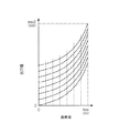
図5は、ミラーデバイスによる変調がある場合の出力値の階調を説明する図である。
図5は、横軸に映像信号の画素値、縦軸に出力値を示したものであり、液晶ライトバルブ51、52、53により空間変調を行った光に、ミラーデバイス30により時間変調を行った光を重畳させて、投射画像の階調を増加する概念を示している。
例えば、液晶ライトバルブ51、52、53およびミラーデバイス30による表現可能な階調が8階調の場合、液晶ライトバルブ51、52、53およびミラーデバイス30の組合せで表現可能な階調は、図中の曲線と縦線との交点として表すことができる(この場合、64階調となる)。
液晶ライトバルブ51、52、53のみで表現可能な階調は、前述した8階調であるので、液晶ライトバルブ51、52、53およびミラーデバイス30を組み合わせることで投射画像の階調を増加させることができる。
FIG. 5 is a diagram for explaining the gradation of the output value when there is modulation by the mirror device.
FIG. 5 shows the pixel value of the video signal on the horizontal axis and the output value on the vertical axis. The light subjected to spatial modulation by the liquid
For example, when the gradations that can be expressed by the liquid
Since the gradations that can be expressed only by the liquid
図6(a)は、ミラーデバイスによる変調が無い場合の出力値のダイナミックレンジおよび階調を説明する図であり、図6(b)は、ミラーデバイスによる変調がある場合の出力値のダイナミックレンジおよび階調を説明する図である。
上述したように、液晶ライトバルブ51、52、53による空間変調を行った光に、ミラーデバイス30による時間変調を行った光を重畳させることで、投射画像のダイナミックレンジを拡大させることができるとともに、階調を増加させることができる。このことを図で示したのが、図6(a)、(b)であり、横軸に映像信号の画素値、縦軸に出力値を示したものである。
例えば、液晶ライトバルブ51、52、53による空間変調のみの場合、図6(a)に示すように、画素値i1からi2に対して出力値o1からo2というダイナミックレンジとして表現することができる。また、画素値i1からi2の間を3段階に分割し、出力値o1からo2の間を3段階の階調として表現することができる。
一方、液晶ライトバルブ51、52、53の変調光およびミラーデバイス30の変調光を重畳させる場合、図6(a)に示すように、画素値i1からi2に対して出力値o′1からo′2という明るい方向に拡大されたダイナミックレンジとして表現することができる。
また、画素値i1からi2の間を3段階に分割した上に、ミラーデバイス30による空間変調で各段階を2段階に分割し(全体として6段階に分割し)、出力値o′1からo′2を6段階の階調として表現することができる。
FIG. 6A is a diagram for explaining the dynamic range and gradation of the output value when there is no modulation by the mirror device, and FIG. 6B is the dynamic range of the output value when there is modulation by the mirror device. It is a figure explaining a gradation.
As described above, the dynamic range of the projected image can be expanded by superimposing the light subjected to the time modulation by the
For example, in the case of only spatial modulation by the liquid
On the other hand, when the modulated light of the liquid
Further, the pixel values i1 to i2 are divided into three stages, and each stage is divided into two stages by spatial modulation by the mirror device 30 (divided into six stages as a whole), and the output values o′1 to o '2 can be expressed as 6 levels of gradation.
次に、本実施形態の投射型表示装置の駆動方法について説明する。
図7は本実施形態における投射型表示装置の駆動回路の構成を示すブロック図である。
本実施形態では、図7に示すように、例えばPCや、DVD、TVアンテナから出力されたアナログ信号である映像信号がA/D変換部81に入力され、デジタル信号に変換されて制御部82に入力される。
なお、投射型表示装置に入力される映像信号がデジタル信号である場合には、アナログ信号をデジタル信号に変換するA/D変換部81は不要となり、制御部82へ直接デジタル信号を入力してもよい。また、投射型表示装置に入力される映像信号が、例えばMPEG2などの圧縮されたデータの場合、A/D変換部81の代わりに圧縮データをデコードするデコーダ部を備え、デコーダ部に圧縮信号を入力してもよいし、制御部82にデコード機能を持たせ、制御部82に圧縮信号を入力してもよい。
Next, a driving method of the projection display device of this embodiment will be described.
FIG. 7 is a block diagram showing the configuration of the drive circuit of the projection display device according to this embodiment.
In the present embodiment, as shown in FIG. 7, for example, a video signal that is an analog signal output from a PC, a DVD, or a TV antenna is input to the A /
When the video signal input to the projection display device is a digital signal, the A /
また、投射型表示装置には、周囲の環境の明るさを検知する光センサ(光検出手段)95が備えられている。光センサ95としては、例えばCCD(Charge Coupled Device)を用いることができ、環境の明るさに応じて信号を出力することができる。光センサ95から出力された信号は、A/D変換部96を介して制御部82に入力される。
なお、光センサ95と制御部82との間には、前述のようにA/D変換部96を配置してもよいし、配置しなくてもよい。
Further, the projection display device is provided with an optical sensor (light detection means) 95 that detects the brightness of the surrounding environment. As the
Note that the A /
制御部82では、複数フレーム分の映像信号および光センサ95の出力から、各色光に対応した液晶ライトバルブ51、52、53の1フレーム当たりの光透過率の制御信号値と、ミラーデバイス30の反射率に対応する制御信号値と、を画素ごとに決定する。複数フレーム分の映像信号は、制御部82からデータ記憶部83に一時的に記憶されていて、必要に応じて制御部82へ読み込まれる。
なお、複数フレーム分の映像信号から前述の各信号値を決定してもよいし、1フレーム分の映像信号から前述の各信号値を決定してもよい。この場合、複数フレーム分の映像信号を一時的に記憶するデータ記憶部83は用いられないため、データ記憶部83を設けない構成であってもよい。
In the
Each signal value described above may be determined from video signals for a plurality of frames, or each signal value described above may be determined from a video signal for one frame. In this case, since the
液晶ライトバルブ51、52、53の光透過率の制御信号(デジタル信号)は、各液晶ライトバルブ51、52、53に対応するD/A変換部84、85、86に入力され、アナログ信号の制御信号に変換される。制御信号(アナログ信号)は、各液晶ライトバルブ51、52、53に対応するパネルドライバ87、88、89に入力され、パネルドライバ87、88、89は、制御信号に基づき液晶ライトバルブ51、52、53の各画素における光透過率を制御する。
ミラーデバイス30の反射率に対応する制御信号(デジタル信号)は、ミラーデバイスドライバ29に入力され、ミラーデバイスドライバ29は制御信号に基づきミラーデバイス30の各ミラーにおける反射率を制御する。
The light transmittance control signals (digital signals) of the liquid
A control signal (digital signal) corresponding to the reflectance of the
上記の構成によれば、液晶ライトバルブ51、52、53により変調された光のみで表示される画像の上に、ミラーデバイス30により変調された第2の光源からの光を重畳させることにより、投射画像のダイナミックレンジの上限を拡大し、より広いダイナミックレンジでの画像表示を可能とし、投射画像の画質を高めることができる。
According to the above configuration, by superimposing the light from the second light source modulated by the
液晶ライトバルブ51、52、53の画素とミラーデバイス30のマイクロミラーとが同じ数だけ形成され、1対1に対応しているため、投射される画像の各画素について、液晶ライトバルブ51、52、53の画素およびミラーデバイス30の画素が対応することになる。その結果、画像の各画素において液晶ライトバルブ51、52、53により変調された光とミラーデバイス30により変調された光とが重畳されるため、投射される画像のダイナミックレンジを画素ごとに柔軟に制御することができる。
Since the same number of pixels of the liquid
ミラーデバイス30は、例えば液晶パネルと比較すると、光の変調効率が高く(液晶パネルは所定の直線偏光しか変調できない)、光源から発生する熱に対しても劣化しにくい(液晶は高熱に弱い)特性を有する。そのため、ミラーデバイス30を用いることにより、強い光を射出する光源を用いることができるとともに、光源から射出された光の利用効率を向上させることができる。
The
複数フレームごとに階調の増加を決定しているため、連続するフレーム間における画像の輝度の連続性を考慮することができ、画素の輝度が不連続に変化することを確実に防止することができる。 Since the increase in gradation is determined for each of a plurality of frames, it is possible to consider the continuity of the luminance of the image between consecutive frames, and to reliably prevent the luminance of the pixels from changing discontinuously. it can.
投射型表示装置内に配置された制御部82でダイナミックレンジの拡大を決定する計算を行うため、通常のTV信号、ビデオ信号などを入力することにより、ダイナミックレンジが拡大されたTV画像や、ビデオ画像を投射することができる。
また、投射型表示装置の外にダイナミックレンジ拡大の計算を行う機器を備える場合と比べ、投射型表示装置のみでダイナミックレンジが拡大された画像を投射できるため、持ち運び性に優れ、設置場所を必要としないといった優れた点を有する。
In order to perform the calculation for determining the expansion of the dynamic range by the
Compared to the case where a device that calculates the dynamic range expansion is provided outside the projection display device, it can project images with an expanded dynamic range using only the projection display device, so it is highly portable and requires an installation location. It has the excellent point of not.
光センサ95の出力に基づいてダイナミックレンジの拡大を決定しているため、明るい環境の時にはダイナミックレンジをより明るく拡大させ、暗い環境の時にはダイナミックレンジの拡大を抑制することができる。そのため、投射型表示装置は周囲の明るさに対して、明るすぎず暗すぎない画像を投射することができ、視聴者に対して見やすい画像を投射することができる。
Since the expansion of the dynamic range is determined based on the output of the
なお、液晶ライトバルブ51、52、53に形成された画素の数と、ミラーデバイス30に形成されたマイクロミラーの数が、上述のように同じであり、1対1に対応していてもよいし、液晶ライトバルブ51、52、53に形成された画素の数がミラーデバイス30に形成されたマイクロミラーの数よりも多くてもよいし、逆に液晶ライトバルブ51、52、53に形成された画素の数がミラーデバイス30に形成されたマイクロミラーの数よりも少なくてもよい。さらには、ミラーデバイス30に形成されたマイクロミラーの数が1つであってもよい。
The number of pixels formed in the liquid
液晶ライトバルブ51、52、53に形成された画素の数がミラーデバイス30に形成されたマイクロミラーの数よりも多い場合には、例えば、液晶ライトバルブ51、52、53に形成された複数の画素により変調された光の複数の照明領域上に、ミラーデバイス30に形成された1つのマイクロミラーにより変調された光を重畳させて、投射される画像のダイナミックレンジの制御を行うことができる。
そのため、ミラーデバイス30を用いる場合、投射画像の画素よりも大きなマイクロミラーを用いることができ、比較的安価で製造容易なミラーデバイスを用いることができる。
When the number of pixels formed in the liquid
Therefore, when using the
液晶ライトバルブ51、52、53に形成された画素の数がミラーデバイス30に形成されたマイクロミラーの数よりも少ない場合には、例えば、液晶ライトバルブ51、52、53に形成された1つの画素により変調された光の照明領域上に、ミラーデバイス30のマイクロミラーにより変調された光が重畳されるため、投射される画像のダイナミックレンジ制御可能な領域は、ミラーデバイス30のマイクロミラーにより規定される。また、階調も同時にミラーデバイス30のマイクロミラーに対応した領域ごとに制御できるため、投射画像の画素よりも大きな画素を有する液晶ライトバルブを用いることができ、比較的安価で製造容易な液晶ライトバルブを用いることができる。
When the number of pixels formed in the liquid
ミラーデバイス30に形成されたマイクロミラーの数が1つの場合であっても、液晶ライトバルブ51、52、53により空間変調された各色光に、複数フレームにわたって時間変調された光源10Bの光を重畳させることにより、ダイナミックレンジを拡大させることができる。
Even if the number of micromirrors formed in the
なお、投射型表示装置には、上述のように、光センサ95を設けて周囲の明るさに応じてダイナミックレンジの拡大を制御してもよいし、光センサ95の代わりに視聴者が好みによりダイナミックレンジの拡大量を指示する入力部を備え、入力部からの信号に基づいてダイナミックレンジを拡大させてもよい。
As described above, the projection display device may be provided with the
なお、投射型表示装置に入力される映像信号(アナログ信号)は、上述のように、A/D変換部81に直接入力されてもよいし、図8に示すように、外部のPCや専用コンバータなどの画像出力機器91に入力させて、ミラーデバイス30を制御する制御信号を画像出力機器91において算出し、映像信号をA/D変換部81に入力し、制御信号を制御部82に入力させてもよい。
この構成によれば、投射型表示装置よりもスペースの制約が少ない外部の画像出力機器91に制御部82より複雑、大型な回路を配置することができ、それにより複雑な演算アルゴリズムによるきめ細かな階調制御を行うことができる。
Note that the video signal (analog signal) input to the projection display device may be directly input to the A /
According to this configuration, a complicated and large circuit can be arranged in the external
なお、光源10Bから射出される光は、上述のように白色光でもよいし、白色光でなくてもよい。例えば、液晶ライトバルブ51、52、53により合成されたカラー画像のバランスが取れていない場合、カラー画像のバランスを取る色光を光源10Bから射出させてもよい。
The light emitted from the
なお、本発明の技術範囲は上記実施形態に限定されるものではなく、本発明の趣旨を逸脱しない範囲において種々の変更を加えることが可能である。
例えば、上記の実施の形態においては、光源10Bからの光をミラーデバイス30により時間変調する構成に適応して説明したが、このミラーデバイス30により時間変調する構成に限られることなく、ミラーデバイスの代わりに液晶ライトバルブを用いる構成など、その他各種のライトバルブを用いる構成に適応することができるものである。
The technical scope of the present invention is not limited to the above embodiment, and various modifications can be made without departing from the spirit of the present invention.
For example, in the above-described embodiment, the light from the
また、上記の実施の形態においては、光源10Bを常時点灯させて、ミラーデバイス30により時間変調する構成に適応して説明したが、このミラーデバイス30により時間変調する構成に限られることなく、光源10Bを点灯、消灯させて時間変調させる構成など、その他各種の構成に適応することができるものである。
In the above embodiment, the
10A・・・光源(第1の光源)、 10B・・・光源(第2の光源) 30・・・ミラーデバイス(第2の光変調手段)、 51、52、53・・・液晶ライトバルブ(第1の光変調手段)、 62・・・クロスプリズム(光合成手段)、 70・・・投射レンズ(投射手段)、 91・・・画像出力機器、 95・・・光センサ(光検出手段)
DESCRIPTION OF
Claims (15)
前記第1の光源から射出される光を変調する第1の光変調手段と、
白色光を射出する第2の光源と、
前記第2の光源から射出される白色光を変調する第2の光変調手段と、
前記第1の光変調手段により変調された光および前記第2の光変調手段により変調された前記白色光を重畳させる光合成手段と、
前記重畳された光を投射する投射手段と、
を有し、
前記第2の光変調手段は、前記第1の光変調手段に入力される映像信号の画素値に基づき、相対的に大きい画素値を示す画素に対しては重畳される前記白色光の出力値が大きく、相対的に小さい画素値を示す画素に対しては重畳される前記白色光の出力値が小さくなるように前記白色光を変調することを特徴とする投射型表示装置。 A first light source that emits light;
First light modulating means for modulating light emitted from the first light source;
A second light source that emits white light;
Second light modulating means for modulating white light emitted from the second light source;
Light combining means for superimposing the light modulated by the first light modulating means and the white light modulated by the second light modulating means;
Projecting means for projecting the superimposed light;
I have a,
The second light modulation means is based on the pixel value of the video signal input to the first light modulation means, and the output value of the white light to be superimposed on a pixel having a relatively large pixel value A projection type display apparatus , wherein the white light is modulated so that an output value of the white light to be superimposed becomes small for a pixel having a large and relatively small pixel value .
前記第2の光変調手段への制御信号の値は前記光検出手段から出力された信号に応じて決定されることを特徴とする請求項1から10のいずれかに記載の投射型表示装置。 Light detection means for detecting ambient light around the projection display device and outputting a signal corresponding to the detected ambient light;
11. The projection type display device according to claim 1, wherein a value of a control signal to the second light modulation unit is determined according to a signal output from the light detection unit.
前記色光分離光学系によって分離された前記複数の色光のそれぞれを変調する複数の前記第1の光変調手段と、 A plurality of first light modulation means for modulating each of the plurality of color lights separated by the color light separation optical system;
前記複数の第1の光変調手段によって変調された光を合成する色光合成光学系と、を有し、 A color light combining optical system for combining the light modulated by the plurality of first light modulation means,
前記光合成手段は、前記色光合成光学系で合成された光および前記第2の光変調手段により変調された前記白色光を重畳させることを特徴とする請求項1から12のいずれか1項に記載の投射型表示装置。 13. The light combining unit superimposes the light combined by the color light combining optical system and the white light modulated by the second light modulation unit. Projection type display device.
前記第1の光変調手段に入力される映像信号の画素値に基づき、相対的に大きい画素値を示す画素に対しては重畳される前記白色光の出力値が大きく、相対的に小さい画素値を示す画素に対しては重畳される前記白色光の出力値が小さくなるように前記白色光を変調する前記第2の光変調手段への制御信号の生成を行う制御手段と、
前記生成された制御信号を前記投射型表示装置に出力する出力手段と、
を有することを特徴とする画像出力機器。 A first light source that emits light, a first light modulation unit that modulates light emitted from the first light source, and a second light source that is different from the first light source and emits white light. and a light source, the second light modulating means for modulating the light emitted from the second light source, modulated by the first light lights modulated by the modulating means and the second light modulating means and said An image output device connected to a projection display device having a light combining unit that superimposes white light and a projection unit that projects the superimposed light,
Based on the pixel value of the video signal input to the first light modulation means, the pixel value indicating the relatively large pixel value is large and the pixel value of the white light to be superimposed is large and relatively small. Control means for generating a control signal to the second light modulation means for modulating the white light so that an output value of the white light superimposed on the pixel indicating
Output means for outputting the generated control signal to the projection display device;
An image output device comprising:
前記第1の光変調手段により変調された光に前記第2の光変調手段により変調された光を重畳し、投射される画像のダイナミックレンジを明るい方向に拡大することを特徴とする投射型表示装置の制御方法。 A first light source that emits light; a first light modulator that modulates light from the first light source; a second light source that emits white light; and the light from the second light source. Second light modulating means, light combining means for superimposing the light modulated by the first light modulating means and the white light modulated by the second light modulating means, and projecting the superimposed light A projection type display device control method comprising:
A projection type display characterized in that the light modulated by the second light modulation means is superimposed on the light modulated by the first light modulation means, and the dynamic range of the projected image is expanded in the bright direction. Control method of the device.
Priority Applications (1)
| Application Number | Priority Date | Filing Date | Title |
|---|---|---|---|
| JP2004028043A JP4507616B2 (en) | 2004-02-04 | 2004-02-04 | Projection type display device, image output device, and control method for projection type display device |
Applications Claiming Priority (1)
| Application Number | Priority Date | Filing Date | Title |
|---|---|---|---|
| JP2004028043A JP4507616B2 (en) | 2004-02-04 | 2004-02-04 | Projection type display device, image output device, and control method for projection type display device |
Related Child Applications (1)
| Application Number | Title | Priority Date | Filing Date |
|---|---|---|---|
| JP2010050841A Division JP4821915B2 (en) | 2010-03-08 | 2010-03-08 | Projection type display device and image output device |
Publications (3)
| Publication Number | Publication Date |
|---|---|
| JP2005221629A JP2005221629A (en) | 2005-08-18 |
| JP2005221629A5 JP2005221629A5 (en) | 2007-03-22 |
| JP4507616B2 true JP4507616B2 (en) | 2010-07-21 |
Family
ID=34997331
Family Applications (1)
| Application Number | Title | Priority Date | Filing Date |
|---|---|---|---|
| JP2004028043A Expired - Fee Related JP4507616B2 (en) | 2004-02-04 | 2004-02-04 | Projection type display device, image output device, and control method for projection type display device |
Country Status (1)
| Country | Link |
|---|---|
| JP (1) | JP4507616B2 (en) |
Families Citing this family (3)
| Publication number | Priority date | Publication date | Assignee | Title |
|---|---|---|---|---|
| JP4432818B2 (en) | 2005-04-01 | 2010-03-17 | セイコーエプソン株式会社 | Image display device, image display method, and image display program |
| BR112013026538B1 (en) * | 2011-04-19 | 2022-06-07 | Dolby Laboratories Licensing Corporation | Highlight projector system, display system and method for displaying an image according to image data |
| WO2020021980A1 (en) * | 2018-07-24 | 2020-01-30 | ソニー株式会社 | Illumination device and projector |
Citations (7)
| Publication number | Priority date | Publication date | Assignee | Title |
|---|---|---|---|---|
| JP2000131668A (en) * | 1998-10-26 | 2000-05-12 | Hitachi Ltd | Light source adjusting device for liquid crystal projector |
| JP2000305040A (en) * | 1999-04-19 | 2000-11-02 | Toshiba Corp | Projection type display device |
| JP2001100689A (en) * | 1999-09-30 | 2001-04-13 | Canon Inc | Display device |
| JP2002287245A (en) * | 2001-03-27 | 2002-10-03 | Ricoh Co Ltd | Image projection device |
| JP2003158747A (en) * | 2001-11-20 | 2003-05-30 | Canon Inc | Image display device |
| JP2003186107A (en) * | 2001-12-17 | 2003-07-03 | Seiko Epson Corp | Projection display device and driving method therefor |
| JP2003195417A (en) * | 2001-12-21 | 2003-07-09 | Eastman Kodak Co | System and method for calibration of display system with linear array modulator |
Family Cites Families (3)
| Publication number | Priority date | Publication date | Assignee | Title |
|---|---|---|---|---|
| JPH08294138A (en) * | 1995-04-21 | 1996-11-05 | Mitsubishi Electric Corp | Liquid crystal projector |
| US6002452A (en) * | 1995-06-08 | 1999-12-14 | Texas Instruments Incorporated | Sequential color display system with spoke synchronous frame rate conversion |
| JPH11184398A (en) * | 1997-12-19 | 1999-07-09 | Casio Comput Co Ltd | Projector |
-
2004
- 2004-02-04 JP JP2004028043A patent/JP4507616B2/en not_active Expired - Fee Related
Patent Citations (7)
| Publication number | Priority date | Publication date | Assignee | Title |
|---|---|---|---|---|
| JP2000131668A (en) * | 1998-10-26 | 2000-05-12 | Hitachi Ltd | Light source adjusting device for liquid crystal projector |
| JP2000305040A (en) * | 1999-04-19 | 2000-11-02 | Toshiba Corp | Projection type display device |
| JP2001100689A (en) * | 1999-09-30 | 2001-04-13 | Canon Inc | Display device |
| JP2002287245A (en) * | 2001-03-27 | 2002-10-03 | Ricoh Co Ltd | Image projection device |
| JP2003158747A (en) * | 2001-11-20 | 2003-05-30 | Canon Inc | Image display device |
| JP2003186107A (en) * | 2001-12-17 | 2003-07-03 | Seiko Epson Corp | Projection display device and driving method therefor |
| JP2003195417A (en) * | 2001-12-21 | 2003-07-09 | Eastman Kodak Co | System and method for calibration of display system with linear array modulator |
Also Published As
| Publication number | Publication date |
|---|---|
| JP2005221629A (en) | 2005-08-18 |
Similar Documents
| Publication | Publication Date | Title |
|---|---|---|
| US7159987B2 (en) | Display device, lighting device and projector | |
| US6758579B2 (en) | Illuminating-light controller, projector, and illuminating-light control method | |
| JP4893004B2 (en) | projector | |
| US8593579B2 (en) | Projection display | |
| US9978315B2 (en) | Image display apparatus and method of controlling image display apparatus | |
| JP2009216857A (en) | Projector, image display system, and image correction method | |
| JP2007206343A (en) | Optical display device and method | |
| JP3891141B2 (en) | Display device | |
| JP3710455B2 (en) | Image display device and light source unit for image display device | |
| WO2015122001A1 (en) | Projector and image display method | |
| JP4821915B2 (en) | Projection type display device and image output device | |
| JP2007241097A (en) | Image display device and projector | |
| US20150022554A1 (en) | Image display device and image display method | |
| JP2008065137A (en) | Liquid crystal projector and image display control method | |
| US9300968B2 (en) | Image processing device, image display device, and projector | |
| JP4507616B2 (en) | Projection type display device, image output device, and control method for projection type display device | |
| JP4539099B2 (en) | Projection type display device, control method for projection type display device, and image output device | |
| JP4501503B2 (en) | Image display device | |
| JP2008089836A (en) | Projector | |
| US9894334B2 (en) | Signal processing circuit, circuit substrate, and projector | |
| JP2009103905A (en) | Projector | |
| JP2005114914A (en) | Projector | |
| JP6314439B2 (en) | Display device and control method of display device | |
| JP2009244850A (en) | Projection display device and driving method | |
| KR20070084273A (en) | Display device with time-multiplexed led light source |
Legal Events
| Date | Code | Title | Description |
|---|---|---|---|
| A521 | Written amendment |
Free format text: JAPANESE INTERMEDIATE CODE: A523 Effective date: 20070131 |
|
| A621 | Written request for application examination |
Free format text: JAPANESE INTERMEDIATE CODE: A621 Effective date: 20070131 |
|
| A521 | Written amendment |
Free format text: JAPANESE INTERMEDIATE CODE: A821 Effective date: 20070201 |
|
| A977 | Report on retrieval |
Free format text: JAPANESE INTERMEDIATE CODE: A971007 Effective date: 20091216 |
|
| A131 | Notification of reasons for refusal |
Free format text: JAPANESE INTERMEDIATE CODE: A131 Effective date: 20100105 |
|
| A521 | Written amendment |
Free format text: JAPANESE INTERMEDIATE CODE: A523 Effective date: 20100308 |
|
| A521 | Written amendment |
Free format text: JAPANESE INTERMEDIATE CODE: A821 Effective date: 20100309 |
|
| TRDD | Decision of grant or rejection written | ||
| A01 | Written decision to grant a patent or to grant a registration (utility model) |
Free format text: JAPANESE INTERMEDIATE CODE: A01 Effective date: 20100413 |
|
| A01 | Written decision to grant a patent or to grant a registration (utility model) |
Free format text: JAPANESE INTERMEDIATE CODE: A01 |
|
| A61 | First payment of annual fees (during grant procedure) |
Free format text: JAPANESE INTERMEDIATE CODE: A61 Effective date: 20100426 |
|
| FPAY | Renewal fee payment (event date is renewal date of database) |
Free format text: PAYMENT UNTIL: 20130514 Year of fee payment: 3 |
|
| R150 | Certificate of patent or registration of utility model |
Free format text: JAPANESE INTERMEDIATE CODE: R150 |
|
| FPAY | Renewal fee payment (event date is renewal date of database) |
Free format text: PAYMENT UNTIL: 20140514 Year of fee payment: 4 |
|
| S531 | Written request for registration of change of domicile |
Free format text: JAPANESE INTERMEDIATE CODE: R313531 |
|
| R350 | Written notification of registration of transfer |
Free format text: JAPANESE INTERMEDIATE CODE: R350 |
|
| LAPS | Cancellation because of no payment of annual fees |