JP4506504B2 - Control device for internal combustion engine - Google Patents
Control device for internal combustion engine Download PDFInfo
- Publication number
- JP4506504B2 JP4506504B2 JP2005051861A JP2005051861A JP4506504B2 JP 4506504 B2 JP4506504 B2 JP 4506504B2 JP 2005051861 A JP2005051861 A JP 2005051861A JP 2005051861 A JP2005051861 A JP 2005051861A JP 4506504 B2 JP4506504 B2 JP 4506504B2
- Authority
- JP
- Japan
- Prior art keywords
- reverse rotation
- signal
- rotation
- counter
- timing
- Prior art date
- Legal status (The legal status is an assumption and is not a legal conclusion. Google has not performed a legal analysis and makes no representation as to the accuracy of the status listed.)
- Expired - Fee Related
Links
Images


Classifications
-
- B—PERFORMING OPERATIONS; TRANSPORTING
- B60—VEHICLES IN GENERAL
- B60W—CONJOINT CONTROL OF VEHICLE SUB-UNITS OF DIFFERENT TYPE OR DIFFERENT FUNCTION; CONTROL SYSTEMS SPECIALLY ADAPTED FOR HYBRID VEHICLES; ROAD VEHICLE DRIVE CONTROL SYSTEMS FOR PURPOSES NOT RELATED TO THE CONTROL OF A PARTICULAR SUB-UNIT
- B60W20/00—Control systems specially adapted for hybrid vehicles
-
- B—PERFORMING OPERATIONS; TRANSPORTING
- B60—VEHICLES IN GENERAL
- B60W—CONJOINT CONTROL OF VEHICLE SUB-UNITS OF DIFFERENT TYPE OR DIFFERENT FUNCTION; CONTROL SYSTEMS SPECIALLY ADAPTED FOR HYBRID VEHICLES; ROAD VEHICLE DRIVE CONTROL SYSTEMS FOR PURPOSES NOT RELATED TO THE CONTROL OF A PARTICULAR SUB-UNIT
- B60W10/00—Conjoint control of vehicle sub-units of different type or different function
- B60W10/04—Conjoint control of vehicle sub-units of different type or different function including control of propulsion units
- B60W10/06—Conjoint control of vehicle sub-units of different type or different function including control of propulsion units including control of combustion engines
-
- F—MECHANICAL ENGINEERING; LIGHTING; HEATING; WEAPONS; BLASTING
- F01—MACHINES OR ENGINES IN GENERAL; ENGINE PLANTS IN GENERAL; STEAM ENGINES
- F01L—CYCLICALLY OPERATING VALVES FOR MACHINES OR ENGINES
- F01L1/00—Valve-gear or valve arrangements, e.g. lift-valve gear
- F01L1/34—Valve-gear or valve arrangements, e.g. lift-valve gear characterised by the provision of means for changing the timing of the valves without changing the duration of opening and without affecting the magnitude of the valve lift
- F01L1/344—Valve-gear or valve arrangements, e.g. lift-valve gear characterised by the provision of means for changing the timing of the valves without changing the duration of opening and without affecting the magnitude of the valve lift changing the angular relationship between crankshaft and camshaft, e.g. using helicoidal gear
- F01L1/352—Valve-gear or valve arrangements, e.g. lift-valve gear characterised by the provision of means for changing the timing of the valves without changing the duration of opening and without affecting the magnitude of the valve lift changing the angular relationship between crankshaft and camshaft, e.g. using helicoidal gear using bevel or epicyclic gear
-
- F—MECHANICAL ENGINEERING; LIGHTING; HEATING; WEAPONS; BLASTING
- F02—COMBUSTION ENGINES; HOT-GAS OR COMBUSTION-PRODUCT ENGINE PLANTS
- F02D—CONTROLLING COMBUSTION ENGINES
- F02D37/00—Non-electrical conjoint control of two or more functions of engines, not otherwise provided for
- F02D37/02—Non-electrical conjoint control of two or more functions of engines, not otherwise provided for one of the functions being ignition
-
- F—MECHANICAL ENGINEERING; LIGHTING; HEATING; WEAPONS; BLASTING
- F02—COMBUSTION ENGINES; HOT-GAS OR COMBUSTION-PRODUCT ENGINE PLANTS
- F02D—CONTROLLING COMBUSTION ENGINES
- F02D41/00—Electrical control of supply of combustible mixture or its constituents
- F02D41/009—Electrical control of supply of combustible mixture or its constituents using means for generating position or synchronisation signals
-
- F—MECHANICAL ENGINEERING; LIGHTING; HEATING; WEAPONS; BLASTING
- F02—COMBUSTION ENGINES; HOT-GAS OR COMBUSTION-PRODUCT ENGINE PLANTS
- F02P—IGNITION, OTHER THAN COMPRESSION IGNITION, FOR INTERNAL-COMBUSTION ENGINES; TESTING OF IGNITION TIMING IN COMPRESSION-IGNITION ENGINES
- F02P5/00—Advancing or retarding ignition; Control therefor
- F02P5/04—Advancing or retarding ignition; Control therefor automatically, as a function of the working conditions of the engine or vehicle or of the atmospheric conditions
- F02P5/145—Advancing or retarding ignition; Control therefor automatically, as a function of the working conditions of the engine or vehicle or of the atmospheric conditions using electrical means
- F02P5/15—Digital data processing
- F02P5/1502—Digital data processing using one central computing unit
- F02P5/1506—Digital data processing using one central computing unit with particular means during starting
-
- G—PHYSICS
- G01—MEASURING; TESTING
- G01M—TESTING STATIC OR DYNAMIC BALANCE OF MACHINES OR STRUCTURES; TESTING OF STRUCTURES OR APPARATUS, NOT OTHERWISE PROVIDED FOR
- G01M15/00—Testing of engines
- G01M15/04—Testing internal-combustion engines
- G01M15/06—Testing internal-combustion engines by monitoring positions of pistons or cranks
-
- F—MECHANICAL ENGINEERING; LIGHTING; HEATING; WEAPONS; BLASTING
- F01—MACHINES OR ENGINES IN GENERAL; ENGINE PLANTS IN GENERAL; STEAM ENGINES
- F01L—CYCLICALLY OPERATING VALVES FOR MACHINES OR ENGINES
- F01L13/00—Modifications of valve-gear to facilitate reversing, braking, starting, changing compression ratio, or other specific operations
- F01L13/02—Modifications of valve-gear to facilitate reversing, braking, starting, changing compression ratio, or other specific operations for reversing
-
- F—MECHANICAL ENGINEERING; LIGHTING; HEATING; WEAPONS; BLASTING
- F01—MACHINES OR ENGINES IN GENERAL; ENGINE PLANTS IN GENERAL; STEAM ENGINES
- F01L—CYCLICALLY OPERATING VALVES FOR MACHINES OR ENGINES
- F01L1/00—Valve-gear or valve arrangements, e.g. lift-valve gear
- F01L1/02—Valve drive
- F01L1/04—Valve drive by means of cams, camshafts, cam discs, eccentrics or the like
- F01L1/047—Camshafts
- F01L1/053—Camshafts overhead type
- F01L2001/0537—Double overhead camshafts [DOHC]
-
- F—MECHANICAL ENGINEERING; LIGHTING; HEATING; WEAPONS; BLASTING
- F01—MACHINES OR ENGINES IN GENERAL; ENGINE PLANTS IN GENERAL; STEAM ENGINES
- F01L—CYCLICALLY OPERATING VALVES FOR MACHINES OR ENGINES
- F01L2800/00—Methods of operation using a variable valve timing mechanism
- F01L2800/03—Stopping; Stalling
-
- F—MECHANICAL ENGINEERING; LIGHTING; HEATING; WEAPONS; BLASTING
- F01—MACHINES OR ENGINES IN GENERAL; ENGINE PLANTS IN GENERAL; STEAM ENGINES
- F01L—CYCLICALLY OPERATING VALVES FOR MACHINES OR ENGINES
- F01L2820/00—Details on specific features characterising valve gear arrangements
- F01L2820/04—Sensors
- F01L2820/041—Camshafts position or phase sensors
-
- F—MECHANICAL ENGINEERING; LIGHTING; HEATING; WEAPONS; BLASTING
- F01—MACHINES OR ENGINES IN GENERAL; ENGINE PLANTS IN GENERAL; STEAM ENGINES
- F01L—CYCLICALLY OPERATING VALVES FOR MACHINES OR ENGINES
- F01L2820/00—Details on specific features characterising valve gear arrangements
- F01L2820/04—Sensors
- F01L2820/042—Crankshafts position
-
- F—MECHANICAL ENGINEERING; LIGHTING; HEATING; WEAPONS; BLASTING
- F01—MACHINES OR ENGINES IN GENERAL; ENGINE PLANTS IN GENERAL; STEAM ENGINES
- F01L—CYCLICALLY OPERATING VALVES FOR MACHINES OR ENGINES
- F01L9/00—Valve-gear or valve arrangements actuated non-mechanically
- F01L9/20—Valve-gear or valve arrangements actuated non-mechanically by electric means
- F01L9/22—Valve-gear or valve arrangements actuated non-mechanically by electric means actuated by rotary motors
-
- F—MECHANICAL ENGINEERING; LIGHTING; HEATING; WEAPONS; BLASTING
- F02—COMBUSTION ENGINES; HOT-GAS OR COMBUSTION-PRODUCT ENGINE PLANTS
- F02D—CONTROLLING COMBUSTION ENGINES
- F02D41/00—Electrical control of supply of combustible mixture or its constituents
- F02D41/009—Electrical control of supply of combustible mixture or its constituents using means for generating position or synchronisation signals
- F02D2041/0095—Synchronisation of the cylinders during engine shutdown
-
- F—MECHANICAL ENGINEERING; LIGHTING; HEATING; WEAPONS; BLASTING
- F02—COMBUSTION ENGINES; HOT-GAS OR COMBUSTION-PRODUCT ENGINE PLANTS
- F02D—CONTROLLING COMBUSTION ENGINES
- F02D2250/00—Engine control related to specific problems or objectives
- F02D2250/06—Reverse rotation of engine
-
- F—MECHANICAL ENGINEERING; LIGHTING; HEATING; WEAPONS; BLASTING
- F02—COMBUSTION ENGINES; HOT-GAS OR COMBUSTION-PRODUCT ENGINE PLANTS
- F02D—CONTROLLING COMBUSTION ENGINES
- F02D41/00—Electrical control of supply of combustible mixture or its constituents
- F02D41/02—Circuit arrangements for generating control signals
- F02D41/04—Introducing corrections for particular operating conditions
- F02D41/06—Introducing corrections for particular operating conditions for engine starting or warming up
-
- Y—GENERAL TAGGING OF NEW TECHNOLOGICAL DEVELOPMENTS; GENERAL TAGGING OF CROSS-SECTIONAL TECHNOLOGIES SPANNING OVER SEVERAL SECTIONS OF THE IPC; TECHNICAL SUBJECTS COVERED BY FORMER USPC CROSS-REFERENCE ART COLLECTIONS [XRACs] AND DIGESTS
- Y02—TECHNOLOGIES OR APPLICATIONS FOR MITIGATION OR ADAPTATION AGAINST CLIMATE CHANGE
- Y02T—CLIMATE CHANGE MITIGATION TECHNOLOGIES RELATED TO TRANSPORTATION
- Y02T10/00—Road transport of goods or passengers
- Y02T10/10—Internal combustion engine [ICE] based vehicles
- Y02T10/40—Engine management systems
Description
本発明は、内燃機関の制御装置に関するものである。 The present invention relates to a control device for an internal combustion engine.
自動車用エンジン等の内燃機関においては、クランク信号及びカム信号からクランク角が把握され、当該クランク角に基づいて燃料噴射及び点火が行われる(特許文献1参照)。 In an internal combustion engine such as an automobile engine, a crank angle is grasped from a crank signal and a cam signal, and fuel injection and ignition are performed based on the crank angle (see Patent Document 1).
ここで、上記クランク信号は、クランクシャフトに取り付けられたクランクロータ近傍のクランクポジションセンサから、同シャフトの回転に伴い例えばクランク角30°毎に出力されるものである。すなわち、上記クランクロータの外形は、このような等間隔のクランク信号がクランクポジションセンサから出力されるような形状に形成される。一方、上記カム信号は、カムシャフトに取り付けられたカムロータ近傍のカムポジションセンサから、カムシャフトの360°回転毎(クランク角720°毎)に出力されるものである。すなわち、上記カムロータの外形は、このようなカム信号がカムポジションセンサから出力されるような形状に形成される。なお、上記カム信号の出力間隔については、同カム信号が気筒判別等に用いられるだけであり、クランク信号のように30°CA毎といった短い出力間隔とする必要はないことから、クランク信号の出力間隔(30°CA毎)に比べてクランク角720°毎という長い間隔にされている。
Here, the crank signal is output from the crank position sensor near the crank rotor attached to the crankshaft, for example, every 30 ° of crank angle as the shaft rotates. That is, the outer shape of the crank rotor is formed in such a shape that crank signals of such equal intervals are output from the crank position sensor. On the other hand, the cam signal is output every 360 ° rotation (
そして、上記クランク信号及びカム信号に基づいてクランク角を把握する際には、例えばクランク信号出力毎にインクリメントされるカウンタが用いられることとなる。このカウンタは、機関始動開始後にスタータによりクランクシャフト及びカムシャフトをある程度回転させ、クランク信号及びカム信号に基づき最初にクランク角が0°になった旨判断できたとき「0」にセットされる。その後、カウンタは、クランク信号出力毎にインクリメントされ、クランク角0°から始まる内燃機関の1サイクルが終了したとき、言い換えればクランク角720°に達してカウンタが720°CAに対応した値になるときには「0」に戻される。従って、0〜720°CAの間にはカウンタがクランク角30°毎に「1」ずつ増加し、そのカウンタに基づいてクランク角を把握することが可能になる。 And when grasping | ascertaining a crank angle based on the said crank signal and a cam signal, the counter incremented for every crank signal output will be used, for example. This counter is set to “0” when the crankshaft and the camshaft are rotated to some extent by the starter after the start of the engine, and it is first determined that the crank angle has become 0 ° based on the crank signal and the cam signal. Thereafter, the counter is incremented every time the crank signal is output, and when one cycle of the internal combustion engine starting from a crank angle of 0 ° is completed, in other words, when the crank angle reaches 720 ° and the counter reaches a value corresponding to 720 ° CA. Returned to "0". Accordingly, the counter increases by “1” every 30 ° of crank angle between 0 and 720 ° CA, and the crank angle can be grasped based on the counter.
ところで、内燃機関の始動性を向上させるには、始動開始後の早期に燃料噴射及び点火を開始することが好ましい。このため、機関運転終了時(クランクシャフト停止時)のカウンタのカウント値を記憶しておき、次回の機関始動開始時には当該記憶されたカウント値をカウンタの初期値とすることで、上記カウント値を機関停止を間においた機関運転間で引き継ぐことが考えられる。このカウント値の引き継ぎを行うことで、機関始動開始後に直ちにカウンタに基づきクランク角を把握することができ、当該クランク角に基づき燃料噴射及び点火を機関始動開始後の早期に開始することが可能になる。 By the way, in order to improve the startability of the internal combustion engine, it is preferable to start fuel injection and ignition at an early stage after the start of the start. For this reason, the count value of the counter at the end of engine operation (when the crankshaft is stopped) is stored, and when the engine starts next time, the stored count value is set as the initial value of the counter. It is conceivable to take over between engine operations with the engine stopped. By taking over the count value, the crank angle can be grasped based on the counter immediately after the engine start is started, and fuel injection and ignition can be started early after the engine start is started based on the crank angle. Become.
しかしながら、内燃機関の運転中からの停止に際しては、燃料噴射や点火の停止後に機関回転速度が圧縮行程での燃焼室内の圧力等による回転抵抗によって徐々に低下してゆき、最終的に上記燃焼室内の圧力によって内燃機関が一旦逆回転した後に機関回転が停止する。このため、クランク信号の出力毎にカウンタをインクリメントするだけでは、上記逆回転の発生後にカウンタと実クランク角との間にずれが生じる。これは、逆回転発生後は、クランク信号の出力毎に実クランク角が小になるのにもかかわらずカウンタがインクリメントされるためである。このため、上記逆回転が発生したときには、カウント値を実クランク角に合わせるための対策を講じないと、クランクシャフト停止時のカウンタのカウント値が実クランク角に対応しなくなる。 However, when the internal combustion engine is stopped during operation, the engine rotational speed gradually decreases due to the rotational resistance due to the pressure in the combustion chamber during the compression stroke after the fuel injection and ignition stop, and finally the combustion chamber The engine rotation is stopped after the internal combustion engine once reversely rotates due to the pressure of. For this reason, only by incrementing the counter for each output of the crank signal, a deviation occurs between the counter and the actual crank angle after the reverse rotation occurs. This is because after the reverse rotation occurs, the counter is incremented every time the crank signal is output, even though the actual crank angle becomes small. For this reason, when the reverse rotation occurs, the counter value when the crankshaft is stopped does not correspond to the actual crank angle unless measures are taken to match the count value to the actual crank angle.
ここで、上記対策を講じるには逆回転発生を検出する必要がある。しかし、クランク信号及びカム信号の出力パターンは内燃機関の正回転時と逆回転時とでほとんど変わらないため、それらの出力パターンに基づいて逆回転の発生を検出することは困難である。そこで、特許文献2の技術を適用して内燃機関の逆回転発生を検出することも考えられる。この特許文献2では、二つのクランクポジションセンサを設け、機関正回転時に二つのクランクポジションセンサからのクランク信号が互いに異なるタイミングで出力されるように各センサを配置している。この場合、二つのセンサからのクランク信号の出力タイミングのずれ状態が内燃機関の正回転時と逆回転時とで異なるようになるため、そのずれ状態に基づき内燃機関での逆回転発生が検出される。
上記のように特許文献2の技術を適用して内燃機関の逆回転発生を検出した場合、逆回転が実際に発生した後の比較的早い時期に当該逆回転の発生を検出することはできる。これは、内燃機関の逆回転に伴う上記ずれ状態の変化が、実際に逆回転が発生した後の比較的早い時期に現れるためである。しかし、こうした逆回転発生の検出では、二つのクランクポジションセンサを設けなければならず、余分にクランクポジションセンサを設ける分の手間やコストアップは避けられない。
When the reverse rotation of the internal combustion engine is detected by applying the technique of
また、逆回転発生の検出を実際の逆回転発生後の比較的早期に行うことができるといっても、実際の逆回転発生から当該逆回転発生の検出までにはある程度の時差(タイミングのずれ)が生じる。このため、当該時差に対応する期間中には上記対策を実施することができず、その時差に起因して上記対策を実施するのが遅れてしまう。その結果、当該対策の実施遅れの分だけ、同対策の実施後にもカウンタと実クランク角との間にずれが残り、クランクシャフト停止時のカウンタのカウント値を実クランク角に対応させることが困難になる。 Even if it can be said that the reverse rotation occurrence can be detected relatively early after the actual reverse rotation occurrence, there is a certain time difference (timing shift) from the actual reverse rotation occurrence to the detection of the reverse rotation occurrence. ) Occurs. For this reason, during the period corresponding to the time difference, the above countermeasure cannot be implemented, and the implementation of the above countermeasure is delayed due to the time difference. As a result, there is a difference between the counter and the actual crank angle even after the implementation of the countermeasure, and it is difficult to match the counter count value when the crankshaft is stopped to the actual crank angle. become.
そして、クランクシャフト停止時のカウンタのカウンタ値が実クランク角に対応していないまま記憶され、次回の機関始動開始時のカウンタの初期値として用いられると、その始動開始後にカウンタに基づいて把握されるクランク角が誤ったものとなる。その結果、始動開始後の初回の燃料噴射及び点火を的確なタイミング(クランク角)で実施できず、内燃機関の始動性を向上させることができなくなる。 The counter value of the counter at the time of stopping the crankshaft is stored without corresponding to the actual crank angle, and is used as the initial value of the counter at the start of the next engine start, and is grasped based on the counter after the start of the start. The crank angle is incorrect. As a result, the first fuel injection and ignition after the start of the engine cannot be performed at an accurate timing (crank angle), and the startability of the internal combustion engine cannot be improved.
本発明はこのような実情に鑑みてなされたものであって、その目的は、新たなセンサを設けることなく機関逆回転の発生を速やかに検出することができ、且つ、クランクシャフト停止時のカウンタを的確に実クランク角に対応させて次回の機関運転時における始動性向上を図ることのできる内燃機関の制御装置を提供することにある。 The present invention has been made in view of such a situation, and an object of the present invention is to quickly detect the occurrence of reverse engine rotation without providing a new sensor, and to provide a counter when the crankshaft is stopped. It is an object of the present invention to provide a control device for an internal combustion engine that can improve the startability at the next engine operation by accurately corresponding to the actual crank angle.
以下、上記目的を達成するための手段及びその作用効果について記載する。
上記目的を達成するため、請求項1記載の発明では、クランクシャフトが一定角度回転する毎にクランク信号を出力するクランクポジションセンサと、前記クランクシャフト及びカムシャフトのうちの一方に連結された回転電機とを備える内燃機関に適用され、前記回転電機のロータ周りに配設されて同ロータの回転によって生じる誘起電圧に応じた信号を出力する複数の回転センサからの信号を加味して前記回転電機を制御するとともに、前記クランク信号の出力毎にインクリメントされるカウンタに基づきクランク角を把握して当該クランク角に基づき内燃機関の運転制御を実行する内燃機関の制御装置において、前記複数の回転センサからの信号の出力パターンが正回転時の出力パターンと異なることに基づき内燃機関での逆回転発生を検出する検出手段と、前記検出手段による逆回転発生の検出後、前記クランク信号の出力毎に前記カウンタをデクリメントするデクリメント手段と、内燃機関での実際の逆回転発生と当該逆回転発生の検出とのタイミングのずれに起因する前記カウンタと実際のクランク角とのずれに対応した減算値を算出し、その減算値の分だけ前記カウンタを減算する減算手段と、機関停止時の前記カウンタのカウント値を記憶しておき、次回の機関始動時には前記記憶されたカウント値を前記カウンタの初期値とする初期値設定手段とを備え、内燃機関の回転時、前記検出手段は、前記クランク信号に基づき各回転センサからの信号の理論上の立ち上がりタイミング及び立ち下がりタイミングを判別し、その理論上の立ち上がりタイミング及び立ち下がりタイミングは機関正回転時における実際の立ち上がりタイミング及び立ち下がりタイミングに対応しており、前記検出手段は、前記理論上のタイミングにて各回転センサからの信号の立ち上がり及び立ち下がりが実際に生じているか否かを判断し、理論上のタイミングにて同信号の立ち上がり及び立ち下がりが実際に生じてない旨判断されることに基づき、内燃機関の逆回転が発生していることを検出し、前記減算手段は、前記検出手段による逆回転発生の検出直前に信号の理論上の立ち上がりタイミング及び立ち下がりタイミングを迎えた回転センサについて、同センサからの信号が前記タイミング以降に立ち上がりと立ち下がりとの間で変化するまでの期間のクランク信号の出力回数に基づき、前記減算値を算出するようにした。
In the following, means for achieving the above object and its effects are described.
In order to achieve the above object, according to the first aspect of the present invention, a crank position sensor that outputs a crank signal each time the crankshaft rotates by a certain angle, and a rotating electrical machine connected to one of the crankshaft and the camshaft. In consideration of signals from a plurality of rotation sensors arranged around the rotor of the rotating electrical machine and outputting signals corresponding to the induced voltage generated by the rotation of the rotor, the rotating electrical machine is And controlling the internal combustion engine based on the crank angle based on a counter that is incremented each time the crank signal is output, and controlling the internal combustion engine based on the crank angle. Reverse rotation generation in an internal combustion engine based on the difference between the signal output pattern and the output pattern during forward rotation Detecting means for detecting, decrementing means for decrementing the counter for each output of the crank signal after detection of occurrence of reverse rotation by the detecting means, detection of actual reverse rotation occurrence in the internal combustion engine and occurrence of the reverse rotation; Subtracting means for calculating a subtraction value corresponding to the deviation between the counter and the actual crank angle due to the timing deviation of the counter, and subtracting the counter by the subtraction value, and the count value of the counter when the engine is stopped And an initial value setting means that uses the stored count value as an initial value of the counter at the next engine start, and when the internal combustion engine is rotated, the detection means is based on the crank signal. Determine the theoretical rise timing and fall timing of the signal from the rotation sensor, and the theoretical rise timing and fall timing The detection timing corresponds to the actual rise timing and fall timing at the time of normal engine rotation, and the detection means actually generates rise and fall of the signal from each rotation sensor at the theoretical timing. And detecting that reverse rotation of the internal combustion engine has occurred based on the determination that the rise and fall of the signal does not actually occur at the theoretical timing , The subtracting means, for a rotation sensor that has reached the theoretical rise timing and fall timing of the signal immediately before detection of reverse rotation by the detection means, the signal from the sensor is between the rise and fall after the timing. The subtraction value is calculated based on the number of output of the crank signal during the period until it changes .
内燃機関においては、通常、クランクシャフトやカムシャフトに各種回転電機が接続されている。こうした回転電機としては、例えばクランクシャフトに連結された発電機があげられる。また、ハイブリッド車両に搭載される内燃機関においては、クランクシャフトに同機関の回転をアシストする電動機が回転電機として連結される。更に、クランクシャフトに対するカムシャフトの相対回転位相を変更するバルブタイミング可変機構を備える内燃機関であって、そのバルブタイミング可変機構として電動式のものを採用した場合には、カムシャフトに連結された上記相対回転位相を変更するための電動機が回転電機として連結される。そして、上述した各種回転電機は、クランクシャフト及びカムシャフトと一体的に回転する。また、回転電機のロータの回転によって誘起電圧が生じると、その誘起電圧に応じた信号が各回転センサから出力される。回転電機は各回転センサからの信号を加味して制御される。 In an internal combustion engine, various rotating electric machines are usually connected to a crankshaft and a camshaft. An example of such a rotating electric machine is a generator connected to a crankshaft. In an internal combustion engine mounted on a hybrid vehicle, an electric motor that assists the rotation of the engine is connected to a crankshaft as a rotating electric machine. Further, when the internal combustion engine is provided with a variable valve timing mechanism for changing the relative rotational phase of the camshaft with respect to the crankshaft, and the electric timing is adopted as the variable valve timing mechanism, the above-mentioned connected to the camshaft. An electric motor for changing the relative rotational phase is connected as a rotating electric machine. And the various rotary electric machines mentioned above rotate integrally with a crankshaft and a camshaft. When an induced voltage is generated by the rotation of the rotor of the rotating electrical machine, a signal corresponding to the induced voltage is output from each rotation sensor. The rotating electrical machine is controlled in consideration of signals from each rotation sensor.
上記各回転センサからの信号の立ち上がり及び立ち下がりについては、それら回転センサがロータ周りに配設されているため、回転センサ毎に異なるタイミングで生じる。すなわち、内燃機関の正回転時における各回転センサからの信号の出力パターンについては、同信号の立ち上がり及び立ち下がりがそれぞれ異なるタイミングで生じるというパターン、言い換えれば比較的短い間隔で上記立ち上がり及び立ち下がりが生じるというパターンになる。そして、内燃機関の逆回転が発生して回転電機のロータも逆回転すると、すぐに、上記信号の立ち上がり及び立ち下がりのタイミングが正回転時と異なるようになり、その信号の出力パターンの変化に基づき同機関の逆回転発生を速やかに検出することができる。また、こうした逆回転発生の検出では、回転電機を制御するのに用いられる回転センサという既存の部品を利用しているため、新たなセンサを設けることなく当該逆回転発生の検出が可能になる。 The rise and fall of the signals from the rotation sensors occur at different timings for each rotation sensor because the rotation sensors are arranged around the rotor. That is, the output pattern of the signal from each rotation sensor during the normal rotation of the internal combustion engine is a pattern in which the rise and fall of the signal occur at different timings, in other words, the rise and fall occur at relatively short intervals. It becomes a pattern that occurs. As soon as the reverse rotation of the internal combustion engine occurs and the rotor of the rotating electrical machine also rotates reversely, the timing of the rise and fall of the signal becomes different from that at the forward rotation, and the output pattern of the signal changes. Based on this, it is possible to quickly detect the reverse rotation of the engine. In addition, in the detection of the occurrence of reverse rotation, since an existing component called a rotation sensor used for controlling the rotating electrical machine is used, the occurrence of the reverse rotation can be detected without providing a new sensor.
そして、内燃機関での逆回転発生が検出されると、以後はカウンタがクランク信号出力毎にデクリメントされる。このため、逆回転発生の検出後にはクランク信号の出力毎に小となってゆくクランク角に合わせて、カウンタをクランク信号の出力毎に小とすることが可能になる。ただし、実際に逆回転が発生してから当該逆回転発生を検出するまでにある程度の時間がかかり、それら逆回転発生と当該逆回転発生の検出との時差(タイミングのずれ)に起因してカウンタのデクリメント開始が遅れてしまう。その結果、上記時差に対応する期間中は、逆回転状態にあるにもかかわらずカウンタがインクリメントされ、カウンタと実クランク角との間にずれが生じる。 When occurrence of reverse rotation in the internal combustion engine is detected, the counter is decremented every time a crank signal is output. For this reason, the counter can be made small for every output of the crank signal in accordance with the crank angle that becomes small for every output of the crank signal after the occurrence of reverse rotation is detected. However, it takes a certain amount of time to detect the occurrence of reverse rotation after the occurrence of reverse rotation, and the counter is caused by the time difference (timing difference) between the occurrence of reverse rotation and the detection of reverse rotation. The start of decrement is delayed. As a result, during the period corresponding to the time difference, the counter is incremented despite the reverse rotation state, and a deviation occurs between the counter and the actual crank angle.
しかし、逆回転発生と当該逆回転発生の検出とのタイミングのずれに起因する前記カウンタと実際のクランク角とのずれは、そのずれに対応した値である減算値の算出、及び、当該減算値の分のカウンタの減算を通じて解消される。これにより、カウンタの実クランク角への対応が図られることとなる。このため、内燃機関の運転停止過程で逆回転が生じたとしても、クランクシャフト停止時のカウンタを的確に実クランク角に対応させることができる。そして、このときのカウンタのカウンタ値は、記憶されて次回の機関始動開始時にカウンタの初期値として用いられる。従って、上記機関始動開始時にカウンタに基づき把握されるクランク角を正確なものとすることができ、その始動開始後の早期に初回の燃料噴射及び点火を的確なタイミング(クランク角)にて実行し、内燃機関の始動性向上を図ることができるようになる。 However, the difference between the counter and the actual crank angle resulting from the timing difference between the occurrence of reverse rotation and the detection of the occurrence of reverse rotation is the calculation of the subtraction value that is a value corresponding to the deviation, and the subtraction value It is eliminated through subtraction of the minute counter. Thereby, correspondence to the actual crank angle of the counter is achieved. For this reason, even if reverse rotation occurs in the process of stopping the operation of the internal combustion engine, the counter when the crankshaft is stopped can accurately correspond to the actual crank angle. The counter value of the counter at this time is stored and used as the initial value of the counter at the next start of engine start. Therefore, the crank angle grasped based on the counter at the start of the engine start can be made accurate, and the first fuel injection and ignition are executed at an accurate timing (crank angle) early after the start of the engine start. As a result, the startability of the internal combustion engine can be improved.
内燃機関の正回転時における各回転センサからの信号の理論上の立ち上がりタイミング及び立ち下がりタイミングについては、クランクポジションセンサからのクランク信号に基づき判別することができる。そして、それらタイミングがきたときに同信号の立ち上がり及び立ち下がりが実際に生じることとなる。一方、内燃機関の逆回転が生じると、回転電機のロータが逆回転して各回転センサからの信号の出力パターンが変化するのに対し、クランク信号の出力パターンは正回転時と変わらない。このため、内燃機関の逆回転時にも、正回転時と同じように、各回転センサからの信号の理論上の立ち上がりタイミング及び立ち下がりタイミングの判別が行われる。ただし、逆回転時には、ロータ逆回転に伴う上記信号の出力パターンの変化が生じていることから、クランク信号に基づき把握される上記信号の理論上の立ち上がりタイミング及び立ち下がりタイミングがきたとしても、そのときに実際に上記信号の立ち上がり及び立ち下がりが生じることはない。上記構成によれば、こうした現象が発生しているか否かが判断され、発生している旨判断されることに基づき、内燃機関の逆回転発生を的確に検出することができる。 The theoretical rise timing and fall timing of the signal from each rotation sensor during the normal rotation of the internal combustion engine can be determined based on the crank signal from the crank position sensor. And when those timings come, the rise and fall of the same signal actually occur. On the other hand, when the reverse rotation of the internal combustion engine occurs, the rotor of the rotating electrical machine rotates reversely and the output pattern of the signal from each rotation sensor changes, whereas the output pattern of the crank signal does not change from the normal rotation. For this reason, the theoretical rise timing and fall timing of the signals from the respective rotation sensors are discriminated at the time of reverse rotation of the internal combustion engine as in the case of normal rotation. However, at the time of reverse rotation, the change in the output pattern of the signal due to the reverse rotation of the rotor occurs, so even if the theoretical rise timing and fall timing of the signal grasped based on the crank signal come. Sometimes the signal does not actually rise or fall. According to the above configuration, whether or not such a phenomenon has occurred is determined, and based on the determination that it has occurred, it is possible to accurately detect the occurrence of reverse rotation of the internal combustion engine.
内燃機関での逆回転発生の有無の判断は、各回転センサからの信号の理論上の立ち上がりタイミング及び立ち下がりタイミング毎に行われる。そして、各回転センサの信号における逆回転発生後の出力パターンは、当該逆回転発生前のパターンを逆回転発生時点を中心として反転させたパターンとなる。このため、逆回転発生の検出直前に信号の理論上の立ち上がりタイミング及び立ち下がりタイミングを迎えた回転センサについては、逆回転発生直後に信号の立ち上がりと立ち下がりとの間での変化が生じることになる。そして、上記回転センサにおける逆回転発生検出前の信号の理論上の立ち上がりタイミング及び立ち下がりタイミングから、逆回転発生後に同信号の立ち上がりと立ち下がりとの間で変化が生じるまでの期間(以下、出力回数判定期間という)は次のような傾向を有する。すなわち、逆回転発生のタイミングが同信号における次回の理論上の立ち上がりタイミング又は立ち下がりタイミング、言い換えれば次回の逆回転発生の有無の判断時点に近いほど長くなり、逆に遠い(判断時点よりも早い)ほど短くなる。また、この出力回数判定期間が長くなるほど、当該期間中でのクランク信号の出力回数は多くなる。 The determination of whether or not reverse rotation has occurred in the internal combustion engine is made at each theoretical rise timing and fall timing of the signal from each rotation sensor. Then, the output pattern after the occurrence of reverse rotation in the signal of each rotation sensor is a pattern obtained by inverting the pattern before the occurrence of reverse rotation around the point of occurrence of reverse rotation. For this reason, for a rotation sensor that has reached the theoretical rise timing and fall timing of the signal immediately before the occurrence of reverse rotation, a change occurs between the rise and fall of the signal immediately after the occurrence of reverse rotation. Become. A period from the theoretical rise timing and fall timing of the signal before the occurrence of reverse rotation in the rotation sensor to a change between the rise and fall of the signal after the occurrence of reverse rotation (hereinafter referred to as output) The frequency determination period) has the following tendency. In other words, the reverse rotation occurrence timing becomes longer as it approaches the next theoretical rise timing or fall timing of the same signal, in other words, the next reverse rotation occurrence determination time, and is farther away (earlier than the determination time). ). Further, the longer the output number determination period, the greater the number of outputs of the crank signal during the period.
従って、上記クランク信号の出力回数が少なくなるほど、実際の逆回転発生から当該逆回転発生の検出までの期間は長くなり、逆回転が発生しているのにカウンタがインクリメントされるという期間も長くなって、同カウンタと実クランク角とのずれが大きくなる。逆に、上記クランク信号の出力回数が多くなるほど、実際の逆回転発生から当該逆回転発生の検出までの期間は短くなり、逆回転が発生しているのにカウンタがインクリメントされるという期間も短くなって、同カウンタと実クランク角とのずれが小さくなる。 Therefore, the smaller the number of times the crank signal is output, the longer the period from the actual reverse rotation occurrence to the detection of the reverse rotation occurrence, and the longer the period during which the counter is incremented even though the reverse rotation has occurred. Thus, the deviation between the counter and the actual crank angle becomes large. Conversely, as the number of times the crank signal is output increases, the period from the actual reverse rotation occurrence to the detection of the reverse rotation occurrence is shortened, and the period in which the counter is incremented even though the reverse rotation has occurred is shortened. Thus, the deviation between the counter and the actual crank angle is reduced.
上記構成によれば、同カウンタと実クランク角とのずれを解消すべくカウンタを減算するための減算値が、当該ずれの大きさに関連するパラメータである上記クランク信号の出力回数に基づき算出される。従って、この減算値の分だけカウンタを減算することで、同カウンタと実クランク角とのずれを的確に解消し、クランクシャフト停止時のカウンタを実クランク角に的確に対応させることができるようになる。 According to the above configuration, the subtraction value for subtracting the counter to eliminate the difference between the counter and the actual crank angle is calculated based on the number of output of the crank signal, which is a parameter related to the magnitude of the difference. The Therefore, by subtracting the counter by this subtraction value, the deviation between the counter and the actual crank angle can be eliminated accurately, and the counter at the time of stopping the crankshaft can be accurately matched to the actual crank angle. Become.
請求項2記載の発明では、請求項1記載の発明において、前記内燃機関は前記カムシャフトに連結された電動機の駆動制御を通じて同カムシャフトの前記クランクシャフトに対する相対回転位相を変更するバルブタイミング可変機構を備えるものであり、前記回転電機は前記バルブタイミング可変機構の電動機であることを要旨とした。 According to a second aspect of the present invention, there is provided a variable valve timing mechanism according to the first aspect , wherein the internal combustion engine changes a relative rotational phase of the camshaft with respect to the crankshaft through drive control of an electric motor coupled to the camshaft. The rotating electrical machine is an electric motor for the variable valve timing mechanism.
上記構成によれば、内燃機関は電動機の駆動制御を通じてクランクシャフトに対するカムシャフトの相対回転位相を変更するバルブタイミング可変機構を備えており、同機構の電動機はカムシャフトと一体回転するようになる。また、電動機のロータの回転によって誘起電圧が生じると、その誘起電圧に応じた信号が各回転センサから出力される。この電動機は各回転センサからの信号を加味して駆動制御される。上記各回転センサからの信号出力パターンについては、同信号の立ち上がり及び立ち下がりがそれぞれ異なるタイミングであって比較的短い間隔で生じるというパターンになる。そして、内燃機関の逆回転が発生して電動機のロータも逆回転すると、すぐに、上記信号の立ち上がり及び立ち下がりのタイミングが正回転時と異なるようになり、その信号の出力パターンの変化に基づき同機関の逆回転発生を速やかに検出することができる。また、こうした逆回転発生の検出では、バルブタイミング可変機構の電動機を駆動制御するのに用いられる回転センサという既存の部品を利用しているため、新たなセンサを設けることなく当該逆回転発生の検出が可能になる。 According to the above configuration, the internal combustion engine includes the variable valve timing mechanism that changes the relative rotation phase of the camshaft with respect to the crankshaft through drive control of the electric motor, and the electric motor of the mechanism rotates integrally with the camshaft. Further, when an induced voltage is generated by the rotation of the rotor of the electric motor, a signal corresponding to the induced voltage is output from each rotation sensor. This electric motor is driven and controlled in consideration of signals from each rotation sensor. The signal output pattern from each rotation sensor is a pattern in which the rise and fall of the signal occur at different timings at relatively short intervals. As soon as the reverse rotation of the internal combustion engine occurs and the rotor of the motor also rotates reversely, the timing of the rise and fall of the signal becomes different from that at the forward rotation, and based on the change in the output pattern of the signal It is possible to quickly detect the reverse rotation of the engine. In addition, since the detection of reverse rotation uses an existing component called a rotation sensor that is used to drive and control the electric motor of the variable valve timing mechanism, detection of the occurrence of reverse rotation is performed without providing a new sensor. Is possible.
以下、本発明を自動車用の多気筒エンジンに適用した一実施形態について図1〜図22を参照して説明する。
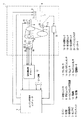
図1のエンジン1においては、その燃焼室2に燃料噴射弁3から噴射された燃料と吸気通路4から吸入される空気とが供給され、それら燃料と空気とからなる混合気に対し点火プラグ5による点火が行われる。このように混合気に対する点火が行われて同混合気が燃焼すると、その際の燃焼エネルギによりエンジン1が駆動されてクランクシャフト6が回転する。なお、クランクシャフト6には、エンジン1の始動時に同シャフト6を強制回転(クランキング)させるためのスタータ25が接続される。
Hereinafter, an embodiment in which the present invention is applied to a multi-cylinder engine for an automobile will be described with reference to FIGS.
In the
また、クランクシャフト6の回転は、吸気カムシャフト7及び排気カムシャフト8に伝達される。これらカムシャフト7,8は、クランクシャフト6からの回転伝達により、クランクシャフト6が720°回転するに当たり360°回転する。こうした吸気カムシャフト7及び排気カムシャフト8の回転を通じてエンジン1の吸気バルブ及び排気バルブが開閉駆動される。
The rotation of the
吸気カムシャフト7には、クランクシャフト6に対する吸気カムシャフト7の相対回転位相を変更して、吸気バルブのバルブタイミングを進角又は遅角させるバルブタイミング可変機構9が設けられている。このバルブタイミング可変機構9としては、吸気カムシャフト7に出力軸10aを連結した電動機10の駆動制御を通じて、クランクシャフト6に対する吸気カムシャフト7の相対回転位相を変更する電動式のものが用いられている。上記電動機10は、その出力軸10aに連結される電動機ロータ17に巻線された励磁コイルと、ステータ(図示せず)に配設されたU相、V相、W相の電機子コイルとを備える巻線界磁式の三相交流回転電気機として構成されている。この電動機10の出力軸10aは、吸気カムシャフト7に連結され、同シャフト7と一体回転する。
The intake camshaft 7 is provided with a variable
上記出力軸10aの回転速度は電動機10の駆動制御を通じて増減される。そして、出力軸10aの回転速度を吸気カムシャフト7の回転速度よりも速くすると、吸気カムシャフト7の回転が増速されて同シャフト7のクランクシャフト6に対する相対回転位相が進角側に変更される。その結果、吸気バルブのバルブタイミングが進角されるようになる。また、出力軸10aの回転速度を吸気カムシャフト7の回転速度よりも遅くすると、吸気カムシャフト7の回転が減速されて同シャフト7のクランクシャフト6に対する相対回転位相が遅角側に変更される。その結果、吸気バルブのバルブタイミングが遅角されるようになる。
The rotational speed of the
次に、クランクシャフト6及び吸気カムシャフト7の回転状態を検出する検出装置について説明する。
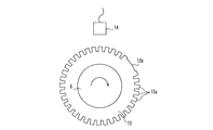
クランクシャフト6にはクランクロータ13が取り付けられ、同クランクロータ13の近傍にはクランクポジションセンサ14が設けられている。図2は、クランクロータ13及びクランクポジションセンサ14を拡大して示した略図である。同図に示されるように、クランクロータ13の外周部には、クランクシャフト6の軸線を中心とする所定角度(この実施形態では10°)毎に合計34個の突起13aと一つの欠歯13bとが設けられている。そして、クランクシャフト6が回転すると、クランクロータ13の各突起13a及び欠歯13bが順次クランクポジションセンサ14の側方を通過する。その結果、クランクポジションセンサ14からは、図4(a)に示されるような信号、すなわちクランク角が10°進む毎に突起13aに対応したパルス状のクランク信号が出力されるとともに、クランク角180°、540°ではの欠歯13bに対応したクランク信号が出力される。この欠歯13bに対応したクランク信号は、突起13aに対応したクランク信号の三つ分の幅を有する。そして、クランクポジションセンサ14から出力されるクランク信号は、エンジン回転速度を求める際などに用いられる。
Next, a detection device that detects the rotation state of the
A
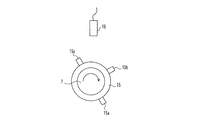
図1に示されるように、吸気カムシャフト7にはカムロータ15が取り付けられ、同カムロータ15の近傍にはカムポジションセンサ16が設けられている。図3は、このカムロータ15及びカムポジションセンサ16を拡大して示した略図である。同図に示されるように、カムロータ15の外周部には合計三つの突起15a〜15cが設けられている。そして、各突起15a〜15cの吸気カムシャフト7の軸線を中心とする角度間隔はそれぞれ、突起15aと突起15bとで90°、突起15bと突起15cとで90°、突起15cと突起15aとで180°になっている。そして、吸気カムシャフト7が回転すると、カムロータ15の各突起15a〜15cが順次カムポジションセンサ16の側方を通過する。その結果、カムポジションセンサ16からは、図4(b)に示されるような信号、すなわちクランク角が約0°、180°、360°になったときに突起15a〜突起15cに対応したパルス状のカム信号が出力される。そして、カムポジションセンサ16から出力されるカム信号は、エンジン1の気筒判別や吸気バルブのバルブタイミング検出などに用いられる。
As shown in FIG. 1, a
次に、電動機10の回転状態を検出する検出装置について説明する。
図1に示されるように、電動機10においては、その出力軸10aに取り付けられた電動機ロータ17の周囲に合計三つの回転センサ、すなわち第1〜第3の回転センサ18〜20が等間隔に設けられている。そして、これら第1〜第3の回転センサ18〜20は、クランクシャフト6及び吸気カムシャフト7と一体回転する出力軸10aの回転に伴う電動機ロータ17の回転時、その回転によって生じる誘起電圧に応じた矩形の信号、例えば図4(c)〜(e)に示されるような信号を出力する。同図から分かるように、第1〜第3の回転センサ18〜20からそれぞれ出力される矩形の信号は、クランク角90°毎に立ち上がりと立ち下がりを繰り返し、互いにクランク角60°分ずれた状態となる。そして、第1〜第3の回転センサ18〜20からの信号は、吸気バルブのバルブタイミングを変更すべく電動機10を駆動制御するにあたって、同電動機10(出力軸10a)の回転速度や回転位置を求める際などに用いられる。
Next, a detection device that detects the rotation state of the
As shown in FIG. 1, in the
次に、エンジン1の制御装置の電気的構成について図1を参照して説明する。
この制御装置は、エンジン1の燃料噴射制御や点火時期制御、及び、吸気バルブのバルブタイミング制御といったエンジン1の運転制御、並びに、スタータ25の駆動制御を行うエンジン制御用コンピュータ11を備えている。エンジン制御用コンピュータ11は、エンジン1の制御にかかる演算処理を実行するCPU、その制御に必要なプログラムやデータの記憶されたROM、CPUの演算結果が一時的に記憶されるRAM、外部との間で信号を入・出力するための入・出力ポート等を備えて構成されている。
Next, the electrical configuration of the control device of the
The control device includes an engine control computer 11 that performs operation control of the
エンジン制御用コンピュータ11には、上述したクランクポジションセンサ14及びカムポジションセンサ16が接続されるほか、更に以下のセンサを含む各種センサが接続されている。
In addition to the crank
・自動車の運転者によって踏み込み操作されるアクセルペダルの踏み込み量(アクセル踏込量)を検出するアクセルポジションセンサ21。
・エンジン1の吸気通路4に設けられたスロットルバルブの開度(スロットル開度)を検出するスロットルポジションセンサ22。
An
A
・上記吸気通路4を通じて燃焼室2に吸入される空気の量を検出するエアフローメータ23。
・「オフ」、[アクセサリ]、「オン」、及び、「スタート」といった四つの切換位置のいずれかに切り換え操作され、現在の切換位置に対応した信号を出力するイグニッションスイッチ24。
An
An
また、エンジン制御用コンピュータ11には電動機10を駆動するための電動機駆動ドライバ12が接続されており、この電動機駆動ドライバ12には上述した第1〜第3の回転センサ18〜20が接続されている。エンジン制御用コンピュータ11は、電動機駆動ドライバ12に対し指令信号を出力することで電動機10を駆動制御する。一方、電動機駆動ドライバ12は、第1〜第3の回転センサ18〜20からの図4(c)〜(e)に示されるような信号を入力すると、それら各信号をエンジン制御用コンピュータ11に出力する。
The engine control computer 11 is connected to an
エンジン制御用コンピュータ11は、上記各種センサから入力した検出信号に基づきエンジン運転状態を把握する。そして、その把握したエンジン運転状態に応じて燃料噴射弁3、点火プラグ5、及び、電動機10を駆動することで、燃料噴射弁3からの燃料噴射の制御、及び、点火プラグ5の点火時期の制御、吸気バルブのバルブタイミング制御が行われる。なお、吸気バルブのバルブタイミング制御を行うべく電動機10を駆動制御する際には、上記回転センサ18〜20からの各信号に基づき現在の電動機10の駆動状態、すなわち出力軸10aの回転速度や回転位置などが把握され、その現在の駆動状態を加味しつつ電動機10の駆動が行われる。このように電動機10を駆動する際に現在の電動機10の駆動状態を加味するのは、その電動機10の駆動を的確に行うためである。
The engine control computer 11 grasps the engine operating state based on the detection signals input from the various sensors. Then, by controlling the
エンジン1の各種運転制御のうち、燃料噴射制御や点火制御といったエンジン1の運転制御については、エンジン1のクランク角に基づき燃料噴射及び点火を行うことによって実現される。このため、エンジン1での燃料噴射及び点火を行うには、エンジン1のクランク角を把握しておく必要がある。そして、クランク角を把握する際には、クランク信号に基づきインクリメントされるカウンタが用いられることとなる。このカウンタは、クランク角0°を基準として突起13aに対応したクランク信号の出力毎にインクリメント(「1」加算)される。なお、欠歯13bに対応したクランク信号の出力時に限っては、同クランク信号が突起13aに対応したクランク信号三つ分に相当することから、カウンタに「3」が加算される。そして、カウンタがクランク角0°から始まるエンジン1の1サイクルが終了したときのクランク角に対応した値、すなわち「72(720°CA)」になったときには、同カウンタが「0」に戻される。従って、0〜720°CAの間にはカウンタがクランク角10°毎に「1」ずつ増加し、そのカウンタに基づいてクランク角を把握することが可能になる。
Among various operation controls of the
次に、エンジン1の始動及び停止について説明する。
通常、エンジン1の始動及び停止は、イグニッションスイッチ24の操作に基づき、エンジン制御用コンピュータ11によるスタータ25の駆動制御、並びに、燃料噴射及び点火の制御を通じて行われる。
Next, starting and stopping of the
Normally, the
すなわち、エンジン停止中、自動車の乗員によりイグニッションスイッチ24が「オフ」から「アクセサリ」、「オン」、「スタート」へと順次切り換えられると、同スイッチ24が「スタート」に切り換えられた時点でエンジン1の始動指令がなされ、スタータ25の駆動を通じてエンジン1のクランキングが開始される。そして、クランキング中に、燃焼室2への燃料と空気との供給、及び、それら燃料と空気とからなる混合気への点火が行われることで、エンジン1の自立運転が開始される。エンジン1の自立運転開始後は、イグニッションスイッチ24が「オン」に操作され、スタータ25の駆動によるクランキングが停止される。
That is, when the
また、エンジン運転中、自動車の乗員によりイグニッションスイッチ24が「オン」から、「アクセサリ」、「オフ」へと順次切り換えられると、同スイッチ24が「アクセサリ」に切り換えられた時点で燃料噴射弁3からの燃料噴射、及び、点火プラグ5による点火が停止され、混合気の燃焼が行われなくなってエンジン1が停止開始される。なお、上記イグニッションスイッチ24の「オン」から「アクセサリ」への切り換えは通常、アイドル運転中に行われることから、上記のようにエンジン1が停止開始された後には、エンジン回転速度が圧縮行程での燃焼室2内の圧力等による回転抵抗によってアイドル回転速度から徐々に低下してゆく。そして、最終的には、上記燃焼室2内の圧力によってエンジン1が一旦逆回転し、その後にエンジン回転が停止することとなる。
Further, when the
ところで、エンジン1の始動性を向上させるには、始動開始後のクランク角の把握を可能な限り早く行い、クランク角に基づく燃料噴射及び点火を始動開始後のできる限り早い時期に開始することが好ましい。このため、エンジン1の運転終了時(クランクシャフト6の停止時)のカウンタのカウント値をエンジン制御用コンピュータ11に設けられた不揮発性のRAMに記憶しておき、次回のエンジン始動開始時に当該記憶されたカウント値をカウンタの初期値とすることが考えられる。この場合、上記カウント値がエンジン停止を間においたエンジン運転間で引き継がれることになる。このため、エンジン始動開始後に直ちにカウンタに基づきクランク角を把握することができ、当該クランク角に基づき燃料噴射及び点火を始動開始後の早期に開始することが可能になる。
By the way, in order to improve the startability of the
ただし、エンジン1の運転中からの停止に際しては、エンジン1が一旦逆回転した後に停止するため、上記逆回転の発生後には実クランク角が小となってゆくのに対しカウンタがクランク信号出力毎に加算されてゆき、それらカウンタと実クランク角との間にずれが生じる。そして、そのずれへの対策を講じないと、クランクシャフト停止時のカウンタのカウント値が実クランク角に対応しなくなる。ここで、上記対策を講じるにはエンジン1での逆回転発生を検出する必要があり、こうした逆回転発生の検出として、例えば[背景技術]の欄に記載した検出の仕方を採用することが考えられる。しかし、[背景技術]の欄に記載した逆回転の検出では、逆回転発生の検出を発生後に速やかに行おうとすると、新たにクランクポジションセンサを追加しなければならず、そのための手間やコストアップは避けられないという問題がある。
However, when the
そこで本実施形態では、第1〜第3の回転センサ18〜20からの信号を利用してエンジン1の逆回転発生を検出することで、その検出を実際の逆回転発生後に速やかに行えるようにする。また、この逆回転発生の検出では、バルブタイミング可変機構9の電動機10を駆動制御するのに用いるべく当該電動機10に設けられた第1〜第3の回転センサ18〜20という既存の部品を利用しているため、新たなセンサを設けることなく逆回転発生を検出することが可能になる。
Therefore, in the present embodiment, by detecting the reverse rotation of the
次に、第1〜第3の回転センサ18〜20からの信号を利用したエンジン1の逆回転の検出について、図4のタイミングチャートを参照して詳しく説明する。
このタイミングチャートの横軸は、エンジン1の正回転時におけるクランク角の変化を表している。このクランク角は、図4(a)に示されるクランク信号、及び、図4(b)に示されるカム信号に基づき確定される。
Next, detection of reverse rotation of the
The horizontal axis of this timing chart represents the change in the crank angle when the
また、クランク角の変化に対する第1〜第3の回転センサ18〜20からの信号の出力パターンは、上述したように図4(c)〜(e)に示されるようなものになる。この図から分かるように、上記各回転センサ18〜20の信号は、クランク角90°毎に立ち上がりと立ち下がりを繰り返し、互いにクランク角60°分ずれた状態となる。これは上記各回転センサ18〜20が電動機ロータ17の周囲に等間隔に設けられているためである。以上のことから、上記信号の立ち上がり及び立ち下がりは、回転センサ毎に異なるタイミング、より詳しくはクランク角30°毎という比較的短い間隔毎に生じる。従って、エンジン正回転時における各回転センサ18〜20からの信号の出力パターンについては、同信号の立ち上がり及び立ち下がりがそれぞれ異なるタイミングで生じるというパターン、言い換えればクランク角30°毎という比較的短い間隔で上記立ち上がり及び立ち下がりが生じるというパターンになる。
Further, the output patterns of the signals from the first to
エンジン正回転時における各回転センサ18〜20からの信号の理論上の立ち上がりタイミング及び立ち下がりタイミングについては、クランク信号に基づき判別することができる。すなわち、本実施形態の場合には、クランク角が0°、30°、60°・・・と30°進む毎に上記立ち上がり及び立ち下がりが生じ、このタイミングを上記理論上の立ち上がり及び立ち下がりのタイミングと判別することができる。そして、エンジン正回転時には、それらのタイミングがきたときに、上記信号の実際の立ち上がり及び立ち下がりが生じることとなる。
The theoretical rise timing and fall timing of the signals from the
ここで、例えばクランク角315°でエンジン1の逆回転が開始された場合を例に、エンジン1の逆回転について考えてみる。
エンジン1が正回転してクランク角315°になったとき、同エンジン1が逆回転したとすると、それ以後のクランク信号の出力パターン及び各回転センサ18〜20からの信号の出力パターンは、クランク角315°前の各出力パターンを図中の破線L1を中心に反転させたパターンとなる。
Here, consider the reverse rotation of the
When the
クランク信号は、正回転時には等間隔毎(クランク角10°毎)に出力されるものであるため、上記逆回転に伴いクランク信号の出力パターンが破線L1を中心に反転したとしても、その出力パターンは正回転時とほとんど変わらない。このため、逆回転後も正回転と同じようにクランク信号に基づき現在のクランク角が確定され、当該確定されたクランク角について0°30CA、°CA、60°CA・・・となる時点が、各回転センサ18〜20からの信号の理論上の立ち上がりタイミング及び立ち下がりタイミングであると判別される。
Since the crank signal is output at regular intervals (every 10 ° of crank angle) during forward rotation, even if the output pattern of the crank signal is inverted around the broken line L1 due to the reverse rotation, the output pattern Is almost the same as during forward rotation. Therefore, the current crank angle is determined based on the crank signal in the same manner as the forward rotation after the reverse rotation, and the time when the determined crank angle becomes 0 ° 30 CA, ° CA, 60 ° CA,... It is determined that the timing is the theoretical rise timing and fall timing of the signals from the
一方、各回転センサ18〜20からの信号の出力パターンには、正回転から逆回転への移行に伴い図5のタイミングチャートに示されるような変化が生じる。同図5において、(a)〜(c)は正回転時における第1〜第3の回転センサからの信号の出力パターンを示している。そして、クランク角315°にてエンジン1が逆回転すると、それ以後の上記信号の出力パターンは、電動機ロータ17の逆回転に伴って図5(d)〜(f)に示されるような出力パターン、すなわちクランク角315°前の出力パターンを図中の破線L1を中心に反転させた出力パターンとなる。
On the other hand, the output pattern of signals from the
この実施形態では、第1〜第3の回転センサ18〜20からの信号の出力パターンがエンジン1の逆回転に伴い正回転時の出力パターンと異なるものになると、そのことに基づきエンジン1の逆回転が発生していることを検出する。
In this embodiment, when the output pattern of the signals from the first to
上記信号の立ち上がり及び立ち下がりは、エンジン1の正回転時、クランク角30°毎という比較的短い間隔で生じている。このため、エンジン1の逆回転が生じると、それに伴い上記信号の立ち上がり及び立ち下がりのタイミングが正回転時と異なるようになるという、上記信号の出力パターンの変化が速やかに生じる。従って、当該出力パターンの変化に基づき逆回転発生を速やかに検出することができる。
The rise and fall of the signal occurs at a relatively short interval of every 30 ° crank angle when the
なお、上記出力パターンの変化に基づく逆回転の検出は、より具体的には、図6のフローチャートに示される手順に従って以下のように行われる。
すなわち、上述したようにエンジン1の正回転時と逆回転時とのいずれの場合であれ、クランク角の確定はクランク信号に基づいて行われ、当該クランク角について0°CA、30°CA、60°CA・・・となる時点が、各回転センサ18〜20からの信号の理論上の立ち上がりタイミング及び立ち下がりタイミングであると判別される(S101)。
More specifically, the reverse rotation detection based on the change in the output pattern is performed as follows according to the procedure shown in the flowchart of FIG.
That is, as described above, whether the
ここで、例えばクランク角315°でエンジン1の逆回転が生じたとすると、クランク信号に基づき確定されたクランク角が330°になった時点が、各回転センサ18〜20からの信号の理論上の立ち上がり及び立ち下がりのタイミングであると判別される。そして、エンジン正回転時には、上記のように判別されたタイミング(330°CA)がくると、対応する信号の立ち上がり又は立ち下がり(この場合は第1の回転センサ18からの信号の立ち下がり(図5(a)参照))が実際に生じる。しかし、エンジン1が逆回転している場合には、各回転センサ18〜20からの信号の出力パターンは正回転時の状態から変化するため、上記タイミング(330°CA)がきても、対応する信号の立ち上がり又は立ち下がりは生じない(図5(d)参照)。
Here, for example, assuming that the reverse rotation of the
こうした現象の有無は、上記タイミングがきたとき(S102:YES)、対応する信号の立ち上がり又は立ち下がりが実際に生じているか否か(S103)によって判断される。すなわち、このタイミングにおいて、上記対応する信号の立ち上がり又は立ち下がりが実際に生じていない場合には(S103:YES)、上述した現象が発生していることになる。そして、その現象が発生していることに基づき、エンジン1の逆回転が発生していることが検出される(S104)。
The presence or absence of such a phenomenon is determined by whether or not the corresponding signal has actually risen or fallen (S103) when the above timing has come (S102: YES). That is, if the corresponding signal does not actually rise or fall at this timing (S103: YES), the above-described phenomenon has occurred. Then, based on the occurrence of the phenomenon, it is detected that reverse rotation of the
以上のような各回転センサ18〜20からの信号の出力パターンを利用した逆回転の検出は、電動機駆動ドライバ12を通じて行われる。そして、エンジン1の逆回転発生が検出されたときには電動機駆動ドライバ12からエンジン制御用コンピュータ11に図5(g)に示されるように逆回転信号「Hi」が出力される。また、エンジン1の逆回転発生が検出されていないときには、電動機駆動ドライバ12からエンジン制御用コンピュータ11に正回転信号「Lo」が出力される。
Detection of reverse rotation using the output patterns of the signals from the
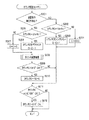
次に、エンジン1での逆回転発生後に生じるカウンタと実クランク角とのずれの対策について、カウンタ算出ルーチンを示す図7のフローチャートを参照して説明する。このカウンタ算出ルーチンは、エンジン制御用コンピュータ11を通じて、クランク信号の出力毎に実行される。
Next, countermeasures against the deviation between the counter and the actual crank angle that occur after reverse rotation in the
同ルーチンでは、クランク角を把握するのに用いられるカウンタCの加減算が行われる。そして、エンジン制御用コンピュータ11は、同ルーチンの実行を通じて加減算される毎にカウンタCのカウント値を不揮発性のRAMに記憶しておき、エンジン停止後の次回のエンジン始動開始時には上記不揮発性のRAMに記憶されたカウント値をカウンタCの初期値として設定する。これにより、エンジン1の運転が終了したときには、クランクシャフト停止時のカウンタCのカウント値が記憶され、次回のエンジン始動開始時には当該カウント値を初期値としてカウンタCの加算が開始されることになる。
In this routine, addition / subtraction of the counter C used for grasping the crank angle is performed. The engine control computer 11 stores the count value of the counter C in the non-volatile RAM every time addition / subtraction is performed through the execution of the routine, and the non-volatile RAM is used when the engine is started next time after the engine is stopped. Is set as the initial value of the counter C. Thus, when the operation of the
同ルーチンにおいては、まず電動機駆動ドライバ12から逆回転信号「Hi」が出力されているか否かに基づき、エンジン1の逆回転発生が検出されているか否かが判断される(S201)。
In this routine, first, based on whether or not the reverse rotation signal “Hi” is output from the
ここで否定判定であって逆回転発生が検出されていない旨判断されると、クランク角を把握するのに用いられるカウンタCを加算するための処理(S202〜S204)が行われる。すなわち、ステップS202では、カウンタCが「18」、「54」以外であるか否かが判断される。ここで肯定判定であれば、エンジン1の正回転時に突起13aに基づくクランク信号が出力されている状況ということになり、ステップS203に進んでカウンタCがインクリメント(「1」加算)される。また、ステップS202で否定判定であれば、エンジン1の正回転時に欠歯13bに基づくクランク信号が出力されている状況ということになり、この場合に限ってはステップS204に進んでカウンタCが「3」加算される。このカウンタCは、上記加算処理を通じて「72(720°CA)」になったとき(S212:YES)、「0」に戻されることとなる(S213)。
If a negative determination is made here that the occurrence of reverse rotation has not been detected, processing (S202 to S204) for adding the counter C used to grasp the crank angle is performed. That is, in step S202, it is determined whether or not the counter C is other than “18” and “54”. If the determination is affirmative, it means that the crank signal based on the
一方、ステップS201で肯定判定であって逆回転発生が検出されている旨判断されると、逆回転発生後のカウンタCと実クランク角とのずれへの対策として、ステップS205〜S208の処理が実行される。すなわち、ステップS205では、カウンタCが「21」、「57」以外であるか否かが判断される。ここで肯定判定であれば、エンジン1の逆回転時に突起13aに基づくクランク信号が出力されている状況ということになり、ステップS206に進んでカウンタCがデクリメント(「1」減算)される。また、ステップS205で否定判定であれば、エンジン1の逆回転時に欠歯13bに基づくクランク信号が出力されている状況ということになり、この場合に限ってはステップS207に進んでカウンタCが「3」減算される。これは欠歯13bに対応するクランク信号が突起13aに対応するクランク信号三つ分に相当するためである。
On the other hand, if the determination in step S201 is affirmative and it is determined that the occurrence of reverse rotation has been detected, the processing in steps S205 to S208 is performed as a countermeasure against the deviation between the counter C after the occurrence of reverse rotation and the actual crank angle. Executed. That is, in step S205, it is determined whether or not the counter C is other than “21” and “57”. If the determination is affirmative, the crank signal based on the
このようにエンジン1での逆回転発生が検出された後には、クランク角が10°進む毎にカウンタCが「1」ずつ減少する。このため、逆回転発生の検出後にはクランク信号の出力毎に小となってゆく実クランク角に合わせて、カウンタCをクランク信号の出力毎に減少させることが可能になる。
Thus, after the occurrence of reverse rotation in the
ただし、実際に逆回転が発生してから当該逆回転発生を検出するのにある程度の時間がかかり、それら逆回転発生と当該逆回転発生の検出との時差(タイミングのずれ)に起因してカウンタCのデクリメント開始が遅れてしまう。例えば、図5の例では315°CAで逆回転が発生したとしても、当該逆回転の発生を検出できるのは330°CAであって、315〜330°CAの間が上記時差に対応する期間ということになる。この期間中は、逆回転状態にあるにもかかわらずカウンタCがクランク信号の出力毎にインクリメントされるため、カウンタCと実クランク角との間にずれが生じることは避けられない。そして、このずれがクランクシャフト停止に至るまで残ったままとなり、クランクシャフト停止時のカウンタCを実クランク角に対応させることが困難になる。 However, it takes a certain amount of time to detect the occurrence of the reverse rotation after the reverse rotation has actually occurred, and the counter is caused by the time difference (timing difference) between the occurrence of the reverse rotation and the occurrence of the reverse rotation. C start of decrement is delayed. For example, in the example of FIG. 5, even if reverse rotation occurs at 315 ° CA, the occurrence of the reverse rotation can be detected at 330 ° CA, and a period between 315 and 330 ° CA corresponds to the time difference. It turns out that. During this period, the counter C is incremented every time the crank signal is output, although it is in the reverse rotation state, it is inevitable that a deviation occurs between the counter C and the actual crank angle. This deviation remains until the crankshaft stops, making it difficult to make the counter C when the crankshaft stops correspond to the actual crank angle.
そして、クランクシャフト停止時のカウンタCのカウント値が実クランク角に対応していないまま記憶され、次回のエンジン始動開始時のカウンタCの初期値として用いられると、その始動開始後にカウンタCに基づいて把握されるクランク角が誤ったものとなる。その結果、エンジン始動開始後の初回の燃料噴射及び点火を的確なタイミング(クランク角)で実施できず、エンジン1の始動性を向上させることができなくなる。
Then, the count value of the counter C when the crankshaft is stopped is stored without corresponding to the actual crank angle, and is used as the initial value of the counter C at the start of the next engine start, based on the counter C after the start of the start. The crank angle that is grasped by the operator is incorrect. As a result, the first fuel injection and ignition after the start of the engine cannot be performed at an accurate timing (crank angle), and the startability of the
そこで本実施形態では、ステップS208(図7)の処理として、エンジン1での実際の逆回転発生と当該逆回転発生の検出との時差(タイミングのずれ)に起因するカウンタCと実クランク角とのずれに対応した減算値Yを算出し、その減算値Yの分だけカウンタCを減算するカウンタ減算処理を実行する。このカウンタ減算処理を通じて、上記時差に起因するカウンタCと実クランク角とのずれを解消し、カウンタCの実クランク角への対応を図ることで、エンジン1の停止過程で逆回転が生じたとしても、クランクシャフト停止時のカウンタCを的確に実クランク角に対応させることができる。従って、上記エンジン始動開始時にカウンタCに基づき把握されるクランク角を正確なものとすることができ、その始動開始後の早期に初回の燃料噴射及び点火を的確なタイミング(クランク角)にて実行し、エンジン1の始動性向上を図ることができるようになる。
Therefore, in the present embodiment, as the processing of step S208 (FIG. 7), the counter C and the actual crank angle resulting from the time difference (timing difference) between the actual reverse rotation occurrence in the
以上のようなステップS205〜S208でのカウンタCの減算を行った後、カウンタCのカウント値が「0」未満になっていれば(S209:YES)、「C←72+C」という式を通じてカウンタCのカウント値が正の値へと変換される(S210)。 After the counter C is subtracted in steps S205 to S208 as described above, if the count value of the counter C is less than “0” (S209: YES), the counter C is expressed through the expression “C ← 72 + C”. The count value is converted to a positive value (S210).
次に、上記カウンタ減算処理(S208)の概要について説明する。
このカウンタ減算処理で用いられる減算値Yは、逆回転発生の検出直前に信号の理論上の立ち上がりタイミング及び立ち下がりタイミングを迎えた回転センサについて、同センサからの信号が上記タイミング以降に立ち上がりと立ち下がりとの間で変化するまでの期間(以下、出力回数判定期間という)のクランク信号の出力回数Xに基づき算出される。
Next, the outline of the counter subtraction process (S208) will be described.
The subtraction value Y used in this counter subtraction process is the value obtained when the signal from the sensor rises and falls after the above timing for the rotation sensor that has reached the theoretical rise and fall timings of the signal immediately before the occurrence of reverse rotation is detected. It is calculated based on the number X of output times of the crank signal in a period (hereinafter, referred to as an output number determination period) until it changes between the two points.
ここで、エンジン1での逆回転発生の有無の判断は、各回転センサ18〜20からの信号の理論上の立ち上がりタイミング及び立ち下がりタイミング毎、すなわち0°CA、30°CA、60°CA・・・・・といったクランク角30°毎に行われる。また、各回転センサ18〜20の信号における逆回転発生後の出力パターンは、当該逆回転発生前のパターンを逆回転発生時点を中心として反転させたパターンとなる。このため、逆回転発生の検出直前に信号の理論上の立ち上がりタイミング及び立ち下がりタイミングを迎えた回転センサについては、逆回転発生直後に信号の立ち上がりと立ち下がりとの間での変化が生じることになる。そして、上記回転センサにおける逆回転発生検出前の信号の理論上の立ち上がりタイミング及び立ち下がりタイミングから、逆回転発生後に同信号の立ち上がりと立ち下がりとの間で変化が生じるまでの期間(出力回数判定期間)は次のような傾向を有する。すなわち、逆回転発生のタイミングが同信号における次回の理論上の立ち上がりタイミング又は立ち下がりタイミング、言い換えれば次回の逆回転発生の有無の判断時点に近いほど長くなり、逆に遠い(判断時点よりも早い)ほど短くなる。また、この出力回数判定期間が長くなるほど、当該期間中でのクランク信号の出力回数は多くなる。
Here, whether or not reverse rotation occurs in the
従って、上記クランク信号の出力回数Xが少なくなるほど、実際の逆回転発生から当該逆回転発生の検出までの期間は長くなり、逆回転が発生しているのにカウンタCがインクリメントされるという期間も長くなって、同カウンタCと実クランク角とのずれが大きくなる。逆に、上記クランク信号の出力回数Xが多くなるほど、実際の逆回転発生から当該逆回転発生の検出までの期間は短くなり、逆回転が発生しているのにカウンタCがインクリメントされるという期間も短くなって、同カウンタCと実クランク角とのずれが小さくなる。 Therefore, as the number X of the crank signal outputs decreases, the period from the actual reverse rotation to the detection of the reverse rotation becomes longer, and the counter C is incremented even though the reverse rotation is occurring. As the length increases, the difference between the counter C and the actual crank angle increases. Conversely, as the number X of output of the crank signal increases, the period from the actual reverse rotation occurrence to the detection of the reverse rotation occurrence becomes shorter, and the counter C is incremented even though the reverse rotation has occurred. And the deviation between the counter C and the actual crank angle is reduced.
しかし、同カウンタCと実クランク角とのずれを解消すべくカウンタCを減算するための減算値Yは、当該ずれの大きさに関係するパラメータである上記クランク信号の出力回数Xに基づき算出される。従って、この減算値Yの分だけカウンタCを減算することで、同カウンタCと実クランク角とのずれを的確に解消し、クランクシャフト停止時のカウンタCを実クランク角度に的確に対応させることができるようになる。 However, the subtraction value Y for subtracting the counter C to eliminate the deviation between the counter C and the actual crank angle is calculated based on the number X of output of the crank signal, which is a parameter related to the magnitude of the deviation. The Therefore, by subtracting the counter C by the subtracted value Y, the deviation between the counter C and the actual crank angle is accurately eliminated, and the counter C when the crankshaft is stopped is accurately associated with the actual crank angle. Will be able to.
なお、上記ずれを解消可能な減算値Yは、逆回転発生時における欠歯13bのクランクポジションセンサ14に対する相対位置から影響を受ける。このため、減算値Yの算出については、以下の[1]〜[3]に示される場合に分けて各々異なる態様で行われることとなる。
The subtracted value Y that can eliminate the deviation is affected by the relative position of the missing tooth 13b with respect to the crank
[1]欠歯13bから離れた位置の突起13aに対応するクランク信号が出力されているときに逆回転が発生した場合。
[2]欠歯13bに対応したクランク信号が出力されているときに逆回転が発生した場合。
[1] When reverse rotation occurs when a crank signal corresponding to the
[2] When reverse rotation occurs when a crank signal corresponding to the missing tooth 13b is output.
[3]欠歯13bの直後に位置する突起13aに対応するクランク信号が出力されているときに逆回転が発生した場合。
次に、上記[1]〜[3]の各状況毎の減算値Yの算出手順について、図8〜図21を参照して詳しく説明する。
[3] When reverse rotation occurs when a crank signal corresponding to the
Next, the calculation procedure of the subtraction value Y for each situation of [1] to [3] will be described in detail with reference to FIGS.
これらの図のうち、図8〜図13は上記[1]の状況に対応しており、図14及び図15は上記[2]の状況に対応しており、図16〜図21は上記[3]の状況に対応している。そして、これら図8〜図21において、(a)はエンジン正回転時のクランク信号の出力パターンを示し、(b)は破線のタイミングでエンジン逆回転が発生した場合のクランク信号の出力パターンを示している。また、図8〜図21の(C)は、逆回転発生の検出直前に信号の理論上の立ち上がり及び立ち下がりタイミングを迎える回転センサからの信号の出力パターンを示している。以下、[1]〜[3]の各状況毎に減算値Yの算出手順について説明する。 Of these figures, FIGS. 8 to 13 correspond to the situation [1], FIGS. 14 and 15 correspond to the situation [2], and FIGS. 3]. 8 to 21, (a) shows the output pattern of the crank signal at the time of normal engine rotation, and (b) shows the output pattern of the crank signal when the engine reverse rotation occurs at the timing of the broken line. ing. FIGS. 8C to 21C show signal output patterns from the rotation sensor that reach the theoretical rise and fall timings of the signal immediately before detection of the occurrence of reverse rotation. Hereinafter, the calculation procedure of the subtraction value Y will be described for each situation [1] to [3].
・上記[1]の状況での減算値Yの算出
こうした[1]の状況としては、例えばクランク角が300〜330°となる期間にあるときに逆回転が発生するという状況があげられる。この期間においては、300°CAにて第3の回転センサ20からの信号の理論上の立ち上がりタイミングを迎え、330°CAにて同信号の理論上の立ち下がりタイミングを迎えることとなる。そして、実際の逆回転発生から当該逆回転発生の検出までの期間、言い換えれば当該期間中のクランク信号の出力回数Xは、300〜330°CAの間のいずれのタイミングで逆回転が発生するかによって変わってくる。
Calculation of the subtraction value Y in the situation [1] The situation [1] includes, for example, a situation in which reverse rotation occurs when the crank angle is in a period of 300 to 330 °. In this period, the theoretical rise timing of the signal from the
クランク角300〜305°の間で逆回転が発生した場合(図8)、逆回転発生後のクランク信号の出力パターンは、図8(b)に示されるように同クランク信号の逆回転発生前の出力パターンを図中の破線を中心として反転させたパターンとなる。また、上記逆回転発生直前である300°CAには第3の回転センサ20からの信号の立ち上がりが生じる。この第3の回転センサ20からの信号の逆回転発生直後の出力パターンも、同信号の逆回転発生前の出力パターンを上記破線を中心として反転させたパターンとなる。このため、逆回転発生直後には第3の回転センサ20からの信号の立ち下がりが生じる。
When reverse rotation occurs between the crank angles of 300 to 305 ° (FIG. 8), the output pattern of the crank signal after the reverse rotation occurs is as shown in FIG. 8B before the reverse rotation of the crank signal occurs. The output pattern is inverted around the broken line in the figure. Further, the signal rises from the
上記のように逆回転が発生した場合、次回に逆回転発生の有無を判断するタイミング(C=33となるタイミング)まで、実クランク角は逆回転発生後のクランク信号出力毎に290°、280°、270°と小さくなってゆくのに対し、カウンタCはクランク信号の出力毎にインクリメントされて「31」、「32」、「33」と増加することになる。そして、カウンタCが「33」になった時点で逆回転発生が検出され、以降はカウンタCがクランク信号出力毎にデクリメントされる。このため、逆回転発生の検出後、初回のクランク信号の出力時にカウンタCは「33」から「1」だけ減算されて「32」となる。しかし、このときの実クランク角は260°であるため、カウンタCは、本来ならば260°CAに対応した値である「26」になるべきであり、その値に対し「6」だけずれていることになる。 When reverse rotation occurs as described above, the actual crank angle is 290 °, 280 for every crank signal output after reverse rotation until the next time when the presence or absence of reverse rotation is determined (timing when C = 33). On the other hand, the counter C is decreased to 270 °, while the counter C is incremented every time the crank signal is output and increases to “31”, “32”, and “33”. Then, when counter C reaches “33”, the occurrence of reverse rotation is detected, and thereafter counter C is decremented for each crank signal output. For this reason, after the occurrence of reverse rotation is detected, the counter C is subtracted by “1” from “33” to “32” when the first crank signal is output. However, since the actual crank angle at this time is 260 °, the counter C should be “26”, which is originally a value corresponding to 260 ° CA, and is shifted by “6” with respect to that value. Will be.
こうしたカウンタCと実クランク角との間のずれは、実際の逆回転発生と当該逆回転発生の検出との時差(タイミングのずれ)に起因しており、その時差が大となるほど大きくなる。そして、この時差については、逆回転発生直前での第3の回転センサ20の信号における理論上の立ち上がりタイミング(300°CA)から同信号の次回の立ち下がりまでの期間(出力回数判定期間)に対応しており、この出力回数判定期間が短くなるほど大になるという傾向を有している。更に、上記出力回数判定期間の長さについては、当該期間中のクランク信号の出力回数Xが多くなるほど長くなる。従って、出力回数Xは、上記カウンタCと実クランク角とのずれに対応したパラメータということになり、この場合は「1」という値をとるようになる。
Such a deviation between the counter C and the actual crank angle is caused by a time difference (timing deviation) between the actual occurrence of reverse rotation and the detection of the occurrence of reverse rotation, and becomes larger as the time difference becomes larger. And about this time difference, it is in the period (output number determination period) from the theoretical rise timing (300 degree CA) in the signal of the
そして、出力回数Xに基づきカウンタCと実クランク角とのずれ(この場合は「6」)に対応した減算値Yの算出が行われる。具体的には、出力回数Xとして「1」を用い、「Y=7−X」という式に基づき減算値Yが算出される。こうして算出された減算値Yは「6」となり、同減算値Yの分だけカウンタCを減算することで、カウンタCが「26」になって実クランク角(260°CA)とのずれが解消され、同カウンタCの実クランク角への対応が図られる。 Based on the output count X, the subtraction value Y corresponding to the difference between the counter C and the actual crank angle (in this case “6”) is calculated. Specifically, “1” is used as the output count X, and the subtraction value Y is calculated based on the expression “Y = 7−X”. The subtraction value Y calculated in this way is “6”, and by subtracting the counter C by the subtraction value Y, the counter C becomes “26” and the deviation from the actual crank angle (260 ° CA) is eliminated. Thus, the counter C is adapted to the actual crank angle.
なお、図9〜図13では各々、逆回転発生のタイミング(図中破線)が305〜310°の間、310〜315°の間、315〜320°の間、320〜325°の間、及び、325〜330°の間となった場合のクランク信号の出力パターン(図中(b))、及び、第3の回転センサ20の出力パターン(図中(c))を表している。 9 to 13, the reverse rotation generation timing (broken line in the figure) is between 305 and 310 °, between 310 and 315 °, between 315 and 320 °, between 320 and 325 °, and , The output pattern of the crank signal (b) in the figure and the output pattern of the third rotation sensor 20 (c) are shown.
これらの図から分かるように、実際の逆回転発生と当該逆回転発生の検出との時差については、逆回転発生のタイミングが第3の回転センサ20からの信号の次回の理論上の立ち下がりタイミング(C=33となるタイミング)、言い換えれば次回の逆回転発生の有無の判断時点に近いほど長くなり、逆に遠い(判断時点よりも早い)ほど短くなる。また、それに対応して、逆回転発生のタイミングが「C=33」となるタイミングに近くなるほど、出力回数判定期間が長くなって出力回数Xが多くなってゆく。より詳しくは、逆回転発生のタイミングが305〜310°の間、310〜315°の間、315〜320°の間、320〜325°の間、325〜330°の間と変化するにつれて、出力回数Xが「2」、「3」、「4」、「5」、「6」と増加してゆく。そして、この出力回数Xを用いて「Y=7−X」という式に基づき減算値Yを算出し、出力回数判定期間終了直後のカウンタCから上記減算値Yを減算することにより、300〜305°の間で逆回転が発生した場合と同様に、カウンタCと実クランク角とのずれが解消され、同カウンタCの実クランク角への対応が図られる。
As can be seen from these figures, regarding the time difference between the actual reverse rotation occurrence and the detection of the reverse rotation occurrence, the timing of the reverse rotation occurrence is the next theoretical fall timing of the signal from the
・上記[2]の状況下での減算値Yの算出
こうした[2]の状況としては、例えばクランク角が180〜210°となる期間にあるときに逆回転が発生するという状況があげられる。この期間においては、180°CAにて第2の回転センサ19からの信号の理論上の立ち上がりタイミングを迎え、210°CAにて同信号の理論上の立ち下がりタイミングを迎えることとなる。そして、実際の逆回転発生から当該逆回転の検出までの期間、言い換えれば当該期間中のクランク信号の出力回数Xは、180〜210°CAの間のいずれのタイミングで逆回転が発生するかによって変わってくる。
Calculation of the subtraction value Y under the situation [2] The situation [2] includes, for example, a situation in which reverse rotation occurs when the crank angle is in a period of 180 to 210 °. In this period, the theoretical rise timing of the signal from the
クランク角180〜195°の間で逆回転が発生した場合(図14)、逆回転発生後のクランク信号の出力パターンは、図14(b)に示されるように同クランク信号の逆回転発生前の出力パターンを図中の破線を中心として反転させたパターンとなる。また、上記逆回転発生直前である180°CAには第2の回転センサ19からの信号の立ち上がりが生じる。この第2の回転センサ19からの信号の逆回転発生直後の出力パターンも、同信号の逆回転発生前の出力パターンを上記破線を中心として反転させたパターンとなる。このため、逆回転発生直後には第2の回転センサ19からの信号の立ち下がりが生じる。
When reverse rotation occurs at a crank angle of 180 to 195 ° (FIG. 14), the output pattern of the crank signal after the reverse rotation occurs is as shown in FIG. 14B before the reverse rotation of the crank signal occurs. The output pattern is inverted around the broken line in the figure. Further, a signal rise from the
上記のように逆回転が発生した場合、カウンタCが「18」となった状態でエンジン1が逆回転し、その後の最初のクランク信号出力が突起13aに対応したものであるのに欠歯13bに対応したものと見なされてカウンタCが「3」加算される。このとき、実際のクランク角は逆回転に伴い180°から170°へと小さくなるのに対し、カウンタCは「18」から「21」へと増加することになる。そして、カウンタCが「21」になると、逆回転発生の有無が判断されてエンジン1での逆回転の発生が検出され、以降はカウンタCがクランク信号出力毎にデクリメントされる。このため、逆回転発生の検出後、初回のクランク信号の出力時にカウンタCは「21」から「1」だけ減算されて「20」となる。しかし、このときの実クランク角は170°から160°へと変化しており、カウンタCは、本来ならば160°CAに対応した値である「16」になるべきであり、その値に対し「4」だけずれていることになる。
When reverse rotation occurs as described above, the
こうしたカウンタCと実クランク角との間のずれは、実際の逆回転発生と当該逆回転発生の検出との時差(タイミングのずれ)に起因しており、その時差が大となるほど大きくなる。そして、この時差については、逆回転発生直前での第2の回転センサ19の信号における理論上の立ち上がりタイミング(180°CA)から同信号の次回の立ち下がりまでの期間(出力回数判定期間)に対応しており、この出力回数判定期間が短くなるほど大になるという傾向を有している。更に、上記出力回数判定期間の長さについては、当該期間中のクランク信号の出力回数Xが多くなるほど長くなる。従って、出力回数Xは、上記カウンタCと実クランク角とのずれに対応したパラメータということになり、この場合は「1」という値をとるようになる。
Such a deviation between the counter C and the actual crank angle is caused by a time difference (timing deviation) between the actual occurrence of reverse rotation and the detection of the occurrence of reverse rotation, and becomes larger as the time difference becomes larger. And about this time difference, it is in the period (output number determination period) from the theoretical rise timing (180 ° CA) in the signal of the
そして、出力回数Xに基づきカウンタCと実クランク角とのずれ(この場合は「4」)に対応した減算値Yの算出が行われる。具体的には、出力回数Xとして「1」を用い、「Y=5−X」という式に基づき減算値Yが算出される。こうして算出された減算値Yは「4」となり、同減算値Yの分だけカウンタCを減算することで、カウンタCが「16」になって実クランク角(160°CA)とのずれが解消され、同カウンタCの実クランク角への対応が図られる。 Based on the output count X, the subtraction value Y corresponding to the difference between the counter C and the actual crank angle (in this case, “4”) is calculated. Specifically, “1” is used as the output count X, and the subtraction value Y is calculated based on the expression “Y = 5-X”. The subtraction value Y thus calculated is “4”, and the counter C is subtracted by the subtraction value Y, so that the counter C becomes “16” and the deviation from the actual crank angle (160 ° CA) is eliminated. Thus, the counter C is adapted to the actual crank angle.
なお、図15では、逆回転発生のタイミング(図中破線)が195〜210°の間となった場合のクランク信号の出力パターン(図中(b))、及び、第2の回転センサ19の出力パターン(図中(c))を表している。
In FIG. 15, the output pattern of the crank signal when the reverse rotation occurrence timing (broken line in the figure) is between 195 and 210 ° ((b) in the figure), and the
この図から分かるように、実際の逆回転発生と当該逆回転発生の検出との時差については、逆回転発生のタイミングが第2の回転センサ19からの信号の次回の理論上の立ち下がりタイミング(C=21となるタイミング)、言い換えれば次回の逆回転発生の有無の判断時点に近いほど長くなる。また、それに対応して、逆回転発生のタイミングが「C=21」となるタイミングに近くなるほど、出力回数判定期間が長くなって出力回数Xが多くなる。従って、逆回転発生のタイミングが195〜210°の間になると、出力回数Xが「2」へと増加する。そして、この出力回数Xを用いて「Y=5−X」という式に基づき減算値Yを算出し、出力回数判定期間終了直後のカウンタC(「20」)から上記減算値Yを減算することにより、180〜195°の間で逆回転が発生した場合と同様に、カウンタCと実クランク角とのずれが解消され、同カウンタCの実クランク角への対応が図られる。 As can be seen from this figure, regarding the time difference between the actual reverse rotation occurrence and the detection of the reverse rotation occurrence, the timing of the reverse rotation occurrence is the next theoretical fall timing of the signal from the second rotation sensor 19 ( C = 21), in other words, the closer to the time when the next reverse rotation occurrence is determined, the longer it is. Correspondingly, as the timing of occurrence of reverse rotation becomes closer to the timing at which “C = 21”, the output count determination period becomes longer and the output count X increases. Accordingly, when the reverse rotation generation timing is between 195 and 210 °, the output count X increases to “2”. Then, the subtraction value Y is calculated based on the expression “Y = 5-X” using the output count X, and the subtraction value Y is subtracted from the counter C (“20”) immediately after the end of the output count determination period. Thus, as in the case where reverse rotation occurs between 180 and 195 °, the deviation between the counter C and the actual crank angle is eliminated, and the counter C is adapted to the actual crank angle.
・上記[3]の状況下での減算値Yの算出
こうした[3]の状況としては、例えばクランク角が210〜215°となる期間にあるときに逆回転が発生するという状況があげられる。この期間においては、210°CAにて第3の回転センサ20からの信号の理論上の立ち下がりタイミングを迎え、240°CAにて同信号の理論上の立ち上がりタイミングを迎えることとなる。そして、実際の逆回転発生から当該逆回転の検出までの期間、言い換えれば当該期間中のクランク信号の出力回数Xは、210〜240°CAの間のいずれのタイミングで逆回転が発生するかによって変わってくる。
Calculation of the subtraction value Y under the situation [3] The situation [3] includes, for example, a situation in which reverse rotation occurs when the crank angle is in a period of 210 to 215 °. In this period, the theoretical falling timing of the signal from the
クランク角210〜215°の間で逆回転が発生した場合(図16)、逆回転発生後のクランク信号の出力パターンは、図16(b)に示されるように同クランク信号の逆回転発生前の出力パターンを図中の破線を中心として反転させたパターンとなる。また、上記逆回転発生直前である210°CAには第3の回転センサ20からの信号の立ち下がりが生じる。この第3の回転センサ20からの信号の逆回転発生直後の出力パターンも、同信号の逆回転発生前の出力パターンを上記破線を中心として反転させたパターンとなる。このため、逆回転発生直後には第3の回転センサ20からの信号の立ち上がりが生じる。
When reverse rotation occurs between the crank angles 210 to 215 ° (FIG. 16), the output pattern of the crank signal after the reverse rotation occurs is as shown in FIG. 16B before the reverse rotation of the crank signal occurs. The output pattern is inverted around the broken line in the figure. Further, the signal from the
上記のように逆回転が発生した場合、カウンタCが「21」となった状態でエンジン1が逆回転し、その後の最初のクランク信号出力が欠歯13bに対応したものであるのに突起13aに対応したものと見なされてカウンタCがインクリメント(「1」加算)される。このとき実際のクランク角は逆回転に伴い210°から180°へと小さくなるのに対し、カウンタCは「21」から「22」へと増加することになる。その後、次回に逆回転発生の有無を判断するタイミング(C=24となるタイミング)まで、実クランク角はクランク信号出力毎に170°、160°と小さくなってゆくのに対し、カウンタCはクランク信号の出力毎にインクリメントされて「23」、「24」と増加する。そして、カウンタCが「24」になった時点で逆回転発生が検出され、以降はカウンタCがクランク信号出力毎にデクリメントされる。このため、逆回転発生の検出後、初回のクランク信号の出力時にカウンタCは「24」から「1」だけ減算されて「23」となる。しかし、このときの実クランク角は150°であるため、カウンタCは、本来ならば150°CAに対応した値である「15」になるべきであり、その値に対し「8」だけずれていることになる。
When reverse rotation occurs as described above, the
こうしたカウンタCと実クランク角との間のずれは、実際の逆回転発生と当該逆回転発生の検出との時差(タイミングのずれ)に起因しており、その時差が大となるほど大きくなる。そして、この時差については、逆回転発生直前での第3の回転センサ20の信号における理論上の立ち下がりタイミング(210°CA)から同信号の次回の立ち上がりまでの期間(出力回数判定期間)に対応しており、この出力回数判定期間が短くなるほど大になるという傾向を有している。更に、上記出力回数判定期間の長さについては、当該期間中のクランク信号の出力回数Xが多くなるほど長くなる。従って、出力回数Xは、上記カウンタCと実クランク角とのずれに対応したパラメータということになり、この場合は「1」という値をとるようになる。
Such a deviation between the counter C and the actual crank angle is caused by a time difference (timing deviation) between the actual occurrence of reverse rotation and the detection of the occurrence of reverse rotation, and becomes larger as the time difference becomes larger. And about this time difference, it is in the period (output number determination period) from the theoretical fall timing (210 ° CA) in the signal of the
そして、出力回数Xに基づきカウンタCと実クランク角とのずれ(この場合は「8」)に対応した減算値Yの算出が行われる。具体的には、出力回数Xとして「1」を用い、「Y=9−X」という式に基づき減算値Yが算出される。こうして算出された減算値Yは「8」となり、同減算値Yの分だけカウンタCを減算することで、カウンタCが「15」になって実クランク角(150°CA)とのずれが解消され、同カウンタCの実クランク角への対応が図られる。 Based on the output count X, the subtraction value Y corresponding to the difference between the counter C and the actual crank angle (in this case, “8”) is calculated. Specifically, “1” is used as the output count X, and the subtraction value Y is calculated based on the formula “Y = 9−X”. The subtraction value Y calculated in this way is “8”. By subtracting the counter C by the subtraction value Y, the counter C becomes “15” and the deviation from the actual crank angle (150 ° CA) is eliminated. Thus, the counter C is adapted to the actual crank angle.
なお、図17〜図21では各々、逆回転発生のタイミング(図中破線)が215〜220°の間、220〜225°の間、225〜230°の間、230〜235°の間、及び、235〜240°の間となった場合のクランク信号の出力パターン(図中(b))、及び、第3の回転センサ20の出力パターン(図中(c))を表している。 In addition, in FIGS. 17-21, the timing of reverse rotation generation | occurrence | production (broken line in a figure) is between 215-220 degrees, between 220-225 degrees, between 225-230 degrees, between 230-235 degrees, and , The output pattern of the crank signal (b) in the figure and the output pattern of the third rotation sensor 20 (c) are shown.
これらの図から分かるように、実際の逆回転発生と当該逆回転発生の検出との時差については、逆回転発生のタイミングが第3の回転センサ20からの信号の次回の理論上の立ち上がりタイミング(C=24となるタイミング)、言い換えれば次回の逆回転発生の有無の判断時点に近いほど長くなり、逆に遠い(判断時点よりも早い)ほど短くなる。また、それに対応して、逆回転発生のタイミングが「C=24」となるタイミングに近くなるほど、出力回数判定期間が長くなって出力回数Xが多くなってゆく。より詳しくは、逆回転発生のタイミングが215〜220°の間、220〜225°の間、225〜230°の間、230〜235°の間、235〜240°の間と変化するにつれて、出力回数Xが「2」、「3」、「4」、「5」、「6」と増加してゆく。そして、この出力回数Xを用いて「Y=9−X」という式に基づき減算値Yを算出し、出力回数判定期間終了直後のカウンタCから上記減算値Yを減算することにより、210〜215°の間で逆回転が発生した場合と同様に、カウンタCと実クランク角とのずれが解消され、同カウンタCの実クランク角への対応が図られる。 As can be seen from these figures, regarding the time difference between the actual reverse rotation occurrence and the detection of the reverse rotation occurrence, the reverse rotation occurrence timing is the next theoretical rise timing of the signal from the third rotation sensor 20 ( (Timing at which C = 24), in other words, it becomes longer as it is closer to the next determination time point of occurrence of reverse rotation, and conversely becomes shorter as it is farther (earlier than the determination time point). Correspondingly, as the timing of occurrence of reverse rotation becomes closer to the timing when “C = 24”, the output count determination period becomes longer and the output count X increases. More specifically, as the timing of occurrence of reverse rotation changes between 215 to 220 °, 220 to 225 °, 225 to 230 °, 230 to 235 °, 235 to 240 °, the output The number of times X increases to “2”, “3”, “4”, “5”, “6”. Then, the subtraction value Y is calculated based on the expression “Y = 9−X” using the output count X, and the subtraction value Y is subtracted from the counter C immediately after the end of the output count determination period. Similarly to the case where reverse rotation occurs between 0 °, the deviation between the counter C and the actual crank angle is eliminated, and the counter C is adapted to the actual crank angle.
次に、カウンタ減算処理(図7のS208)の詳細な実行手順について、カウンタ減算処理ルーチンを示す図22のフローチャートを参照して説明する。このカウンタ減算処理ルーチンは、エンジン制御用コンピュータ11を通じて、図7のカウンタ算出ルーチンにおけるステップS208に進む毎に実行される。 Next, the detailed execution procedure of the counter subtraction process (S208 in FIG. 7) will be described with reference to the flowchart of FIG. 22 showing the counter subtraction process routine. This counter subtraction processing routine is executed every time the process proceeds to step S208 in the counter calculation routine of FIG.
同ルーチンにおいては、エンジン停止までの間にカウンタ減算処理が既に行われているか否かを判断するためのフラグFが「0(未完)」であるか否かが判断される(S301)。ここで肯定判定がなされると、逆回転発生直前に信号の理論上の立ち上がりタイミング及び立ち下がりタイミングを迎えた回転センサについて、上記タイミング以降に同センサからの信号の立ち上がりと立ち下がりとの間での変化が生じたか否かが判断される(S302)。そして、ここで肯定判定であれば出力回数判定期間が終わったことになり、その出力回数判定期間中のクランク信号の出力回数Xに基づき、上記[1]〜[3]の各状況毎に減算値Yを算出するための処理(S303〜307)が実行される。 In this routine, it is determined whether or not the flag F for determining whether or not the counter subtraction process has already been performed before the engine is stopped is “0 (incomplete)” (S301). If an affirmative determination is made here, between the rise and fall of the signal from the sensor after the above timing for the rotation sensor that has reached the theoretical rise timing and fall timing of the signal immediately before the reverse rotation occurs. It is determined whether or not a change has occurred (S302). Then, if the determination is affirmative, the output number determination period has ended, and subtraction is performed for each of the above conditions [1] to [3] based on the output number X of the crank signal during the output number determination period. Processing (S303 to 307) for calculating the value Y is executed.
具体的には、逆回転発生検出時のカウンタCが「21」または「57」でないこと(S303:YES)、すなわち上記[2]の状況でないこと、及び、同カウンタCが「24」または「57」でないこと、すなわち上記[3]の状況でないことを条件に、上記[1]の状況である旨判断され、ステップS305の処理に進む。この処理では、出力回数判定期間中のクランク信号の出力回数Xに基づき「Y=7−X」という式を用いて減算値Yが算出される(S305)。また、逆回転発生時のカウンタCが「21」または「57」であるとき(S303:NO)、すなわち上記[2]の状況であるときには、出力回数判定期間中のクランク信号の出力回数Xを用いて「Y=5−X」という式に基づき減算値Yが算出される(S306)。更に、逆回転発生時のカウンタCが「24」または「60」であるとき(S304:NO)、すなわち上記[3]の状況であるときには、出力回数判定期間中のクランク信号の出力回数Xを用いて「Y=9−X」という式に基づき減算値Yが算出される(S307)。 Specifically, the counter C when the reverse rotation occurrence is detected is not “21” or “57” (S303: YES), that is, the situation of the above [2], and the counter C is “24” or “ If it is not “57”, that is, it is not the situation of [3], it is determined that the situation is [1], and the process proceeds to step S305. In this process, the subtraction value Y is calculated using the expression “Y = 7−X” based on the output number X of the crank signal during the output number determination period (S305). Further, when the counter C at the time of reverse rotation is “21” or “57” (S303: NO), that is, in the situation of [2] above, the number of outputs X of the crank signal during the output number determination period is set. The subtraction value Y is calculated based on the expression “Y = 5-X” (S306). Further, when the counter C when the reverse rotation occurs is “24” or “60” (S304: NO), that is, in the above-mentioned situation [3], the number of outputs X of the crank signal during the output number determination period is set. The subtraction value Y is calculated based on the expression “Y = 9−X” (S307).
このように減算値Yが算出されると、カウンタCが減算値Yだけ減算される(S308)。その後、フラグFが「1(完了)」に設定され、以降にステップS302〜S308の処理(カウンタ減算処理)が実施されることはなくなる。なお、フラグFはエンジン停止時に初期値である「0(未完)」に設定されることとなる。 When the subtraction value Y is calculated in this way, the counter C is subtracted by the subtraction value Y (S308). Thereafter, the flag F is set to “1 (completed)”, and the processing (counter subtraction processing) in steps S302 to S308 is not performed thereafter. The flag F is set to “0 (incomplete)” which is an initial value when the engine is stopped.
以上詳述した本実施形態によれば、以下に示す効果が得られるようになる。
(1)エンジン1の停止過程での逆回転発生の検出には、バルブタイミング可変機構9を駆動するための電動機10に設けられた第1〜第3の回転センサ18〜20が利用される。これら回転センサ18〜20は、吸気バルブのバルブタイミング制御を行うべく電動機10を駆動制御するために設けられたものである。このように既存のセンサである第1〜第3の回転センサ18〜20を用いてエンジン1の逆回転発生を検出しているため、その逆回転発生の検出のために新たなセンサやロータを設ける必要はない。
According to the embodiment described in detail above, the following effects can be obtained.
(1) The first to
(2)第1〜第3の回転センサ18〜20は電動機ロータ17の周りに等間隔をおいて配設されており、各センサ18からの信号の立ち上がり及び立ち下がりはエンジン1の正回転時にはクランク角30°毎という比較的短い間隔で生じる。そして、エンジン1の逆回転時には、それに伴い上記信号の立ち上がり及び立ち下がりのタイミングが正回転時と異なるようになるという、上記信号の出力パターンの変化が速やかに生じる。従って、当該出力パターンの変化に基づき逆回転発生を速やかに検出することができる。
(2) The first to
(3)第1〜第3の回転センサ18〜20からの信号の出力パターンが正回転時の状態から変化しているか否かは、クランク信号に基づき判別される上記信号の理論上の立ち上がり及び立ち下がりタイミングにて、実際に同信号の立ち上がり及び立ち下がりが生じているか否かに基づき判断される。逆回転が発生している場合、上記タイミングがきても、対応する信号の立ち上がり及び立ち下がりが実際に生じることはない。このため、上述した判断に基づき、各回転センサ18〜20からの信号の出力パターンの正回転時の状態からの変化、言い換えればエンジン1の逆回転発生を的確に検出することができる。
(3) Whether the output pattern of the signals from the first to
(4)エンジン1の停止過程で逆回転発生が検出されると、以後はクランク角を把握するためのカウンタCがクランク信号出力毎にデクリメントされる。このため、逆回転発生の検出後にはクランク信号の出力毎に小となってゆく実クランク角に合わせて、カウンタCをクランク信号の出力毎に小とすることが可能になる。ただし、実際に逆回転が発生してから当該逆回転発生を検出するまでにある程度の時間がかかり、それら逆回転発生と当該逆回転発生の検出との時差(タイミングのずれ)に起因してカウンタCのデクリメント開始が遅れてしまう。その結果、上記時差に対応する期間中は、逆回転状態にあるにもかかわらずカウンタCがインクリメントされ、カウンタCと実クランク角との間にずれが生じる。しかし、逆回転発生と当該逆回転発生の検出とのタイミングのずれに起因するカウンタCと実際のクランク角とのずれは、そのずれに対応した値である減算値Yの算出、及び、当該減算値Yの分のカウンタCの減算を通じて解消される。こうしたカウンタ減算処理を行うことで、カウンタCの実クランク角への対応が図られる。このため、エンジン1の運転停止過程で逆回転が生じたとしても、クランクシャフト停止時のカウンタCを的確に実クランク角に対応させることができる。そして、このときのカウンタCのカウンタ値は、記憶されて次回のエンジン始動開始時にカウンタCの初期値として用いられる。従って、上記エンジン始動開始時にカウンタCに基づき把握されるクランク角を正確なものとすることができ、その始動開始後の早期に初回の燃料噴射及び点火を的確なタイミング(クランク角)にて実行し、エンジンの始動性向上を図ることができるようになる。
(4) When the occurrence of reverse rotation is detected while the
(5)エンジン1での逆回転発生の有無の判断は、各回転センサ18〜20からの信号の理論上の立ち上がりタイミング及び立ち下がりタイミング毎に行われる。そして、各回転センサ18〜20の信号における逆回転発生後の出力パターンは、当該逆回転発生前のパターンを逆回転発生時点を中心として反転させたパターンとなる。このため、逆回転発生の検出直前に信号の理論上の立ち上がりタイミング及び立ち下がりタイミングを迎えた回転センサについては、逆回転発生直後に信号の立ち上がりと立ち下がりとの間での変化が生じることになる。そして、上記回転センサにおける逆回転発生検出前の信号の理論上の立ち上がりタイミング及び立ち下がりタイミングから、逆回転発生後に同信号の立ち上がりと立ち下がりとの間での変化が生じるまでの期間(出力回数判定期間)は次のような傾向を有する。すなわち、逆回転発生のタイミングが同信号における次回の理論上の立ち上がりタイミング又は立ち下がりタイミング、言い換えれば次回の逆回転発生の有無の判断時点に近いほど長くなり、逆に遠い(判断時点よりも早い)ほど短くなる。そして、この出力回数判定期間が長くなるほど、当該機関中でのクランク信号の出力回数Xは多くなる。従って、上記出力回数Xが少なくなるほど、実際の逆回転発生から当該逆回転発生の検出までの期間は長くなり、逆回転が発生しているのにカウンタCがインクリメントされるという期間も長くなって、同カウンタCと実クランク角のずれが大きくなる。逆に、上記出力回数Xが多くなるほど、実際の逆回転発生から当該逆回転発生の検出までの期間は短くなり、逆回転が発生しているのにカウンタCがインクリメントされるという期間も短くなって、同カウンタCと実クランク角とのずれが小さくなる。そして、カウンタCと実クランク角とのずれを解消すべくカウンタCを減算するための減算値Yは、当該ずれの大きさに関連するパラメータである上記出力回数Xに基づき算出される。従って、この減算値Yの分だけカウンタCを減算することで、同カウンタCと実クランク角とのずれを的確に解消し、クランクシャフト停止時のカウンタCを実クランク各に的確に対応させることができるようになる。
(5) The determination as to whether or not reverse rotation has occurred in the
なお、上記実施形態は、例えば以下のように変更することもできる。
・第1〜第3の回転センサ18〜20からの信号の出力パターンが正回転時の状態から変化しているか否かの判断として、上記(3)に記載した判断の仕方以外の仕方を採用することもできる。例えば、あるクランク角での各回転センサ18〜20からの信号の状態(「Hi」か「Lo」か)をエンジン正回転時の状態と比較し、ここで正回転時の状態と異なっている場合に、上記信号の出力パターンが正回転時の状態から変化していること、言い換えればエンジン1の逆回転が発生していることを検出するようにしてもよい。
In addition, the said embodiment can also be changed as follows, for example.
A method other than the determination method described in (3) above is adopted as a determination as to whether or not the output pattern of signals from the first to
・減算値Yを逆回転発生から当該逆回転発生の検出までの期間に対応する値として算出するのに、上記(5)に記載した算出の仕方以外の仕方を採用してもよい。
・クランクシャフトやカムシャフトに連結される回転電機として、バルブタイミング可変機構9の電動機10を例示したが、本発明はこれに限定されない。例えば、エンジンのクランクシャフトには通常は発電機が連結されるが、この発電機を上記回転電機として用いてもよい。また、ハイブリッド自動車に搭載されるエンジンにおいては、クランクシャフトに同エンジンの回転をアシストする電動機が連結されるが、この電動機を上記回転電機として用いてもよい。
In order to calculate the subtraction value Y as a value corresponding to the period from the occurrence of reverse rotation to the detection of the occurrence of reverse rotation, a method other than the calculation method described in (5) above may be employed.
-Although the
・クランクポジションセンサ14及びクランクロータ13については、必ずしもクランクシャフト6側に設ける必要はなく、例えば排気カムシャフト8側に設けて同シャフト8の回転に基づきクランクシャフト6の回転状態を検出するようにしてもよい。
The crank
1…エンジン、2…燃焼室、3…燃料噴射弁、4…吸気通路、5…点火プラグ、6…クランクシャフト、7…吸気カムシャフト、8…排気カムシャフト、9…バルブタイミング可変機構、10…電動機(回転電機)、10a…出力軸、11…エンジン制御用コンピュータ(検出手段、デクリメント手段、減算手段、初期値設定手段)、12…電動機駆動ドライバ(検出手段)、13…クランクロータ、13a…突起、13b…欠歯、14…クランクポジションセンサ、15…カムロータ、15a〜15c…突起、16…カムポジションセンサ、17…電動機ロータ、18…第1の回転センサ、19…第2の回転センサ、20…第3の回転センサ、21…アクセルポジションセンサ、22…スロットルポジションセンサ、23…エアフローメータ、24…イグニッションスイッチ、25…スタータ。
DESCRIPTION OF
Claims (2)
前記複数の回転センサからの信号の出力パターンが正回転時の出力パターンと異なることに基づき内燃機関での逆回転発生を検出する検出手段と、
前記検出手段による逆回転発生の検出後、前記クランク信号の出力毎に前記カウンタをデクリメントするデクリメント手段と、
内燃機関での実際の逆回転発生と当該逆回転発生の検出とのタイミングのずれに起因する前記カウンタと実際のクランク角とのずれに対応した減算値を算出し、その減算値の分だけ前記カウンタを減算する減算手段と、
機関停止時の前記カウンタのカウント値を記憶しておき、次回の機関始動時には前記記憶されたカウント値を前記カウンタの初期値とする初期値設定手段と、
を備え、内燃機関の回転時、前記検出手段は、前記クランク信号に基づき各回転センサからの信号の理論上の立ち上がりタイミング及び立ち下がりタイミングを判別し、その理論上の立ち上がりタイミング及び立ち下がりタイミングは機関正回転時における実際の立ち上がりタイミング及び立ち下がりタイミングに対応しており、
前記検出手段は、前記理論上のタイミングにて各回転センサからの信号の立ち上がり及び立ち下がりが実際に生じているか否かを判断し、理論上のタイミングにて同信号の立ち上がり及び立ち下がりが実際に生じてない旨判断されることに基づき、内燃機関の逆回転が発生していることを検出し、
前記減算手段は、前記検出手段による逆回転発生の検出直前に信号の理論上の立ち上がりタイミング及び立ち下がりタイミングを迎えた回転センサについて、同センサからの信号が前記タイミング以降に立ち上がりと立ち下がりとの間で変化するまでの期間のクランク信号の出力回数に基づき、前記減算値を算出することを特徴とする内燃機関の制御装置。 Applied to an internal combustion engine comprising a crank position sensor that outputs a crank signal each time the crankshaft rotates by a certain angle, and a rotating electrical machine connected to one of the crankshaft and camshaft, and around the rotor of the rotating electrical machine And a counter that is incremented every time the crank signal is output while controlling the rotating electrical machine in consideration of signals from a plurality of rotation sensors that output signals corresponding to the induced voltage generated by rotation of the rotor. In the control device for an internal combustion engine that grasps the crank angle based on the crank angle and executes the operation control of the internal combustion engine based on the crank angle,
Detecting means for detecting reverse rotation in the internal combustion engine based on an output pattern of signals from the plurality of rotation sensors being different from an output pattern at the time of forward rotation;
Decrementing means for decrementing the counter every output of the crank signal after detection of reverse rotation occurrence by the detecting means;
Calculate a subtraction value corresponding to the deviation between the counter and the actual crank angle due to the timing difference between the actual reverse rotation occurrence in the internal combustion engine and the detection of the reverse rotation occurrence, and the subtraction value corresponding to the subtraction value Subtracting means for subtracting the counter;
Initial value setting means for storing the count value of the counter when the engine is stopped, and setting the stored count value as the initial value of the counter at the next engine start;
When the internal combustion engine rotates, the detection means determines a theoretical rise timing and fall timing of the signal from each rotation sensor based on the crank signal, and the theoretical rise timing and fall timing are It corresponds to the actual rise timing and fall timing at the time of engine normal rotation,
The detection means determines whether or not the rise and fall of the signal from each rotation sensor actually occurs at the theoretical timing, and the rise and fall of the signal is actually caused at the theoretical timing. And detecting that the reverse rotation of the internal combustion engine has occurred ,
For the rotation sensor that has reached the theoretical rise timing and fall timing of the signal immediately before the detection of the occurrence of reverse rotation by the detection means, the subtractor means that the signal from the sensor rises and falls after the timing. A control device for an internal combustion engine , wherein the subtraction value is calculated based on the number of outputs of a crank signal during a period until it changes between .
請求項1記載の内燃機関の制御装置。 The internal combustion engine includes a valve timing variable mechanism that changes a relative rotation phase of the camshaft with respect to the crankshaft through drive control of an electric motor connected to the camshaft, and the rotating electrical machine includes the valve timing variable mechanism. The control device for an internal combustion engine according to claim 1 , wherein the control device is an electric motor.
Priority Applications (5)
| Application Number | Priority Date | Filing Date | Title |
|---|---|---|---|
| JP2005051861A JP4506504B2 (en) | 2005-02-25 | 2005-02-25 | Control device for internal combustion engine |
| CN200680006215A CN100590311C (en) | 2005-02-25 | 2006-02-22 | Apparatus and method for controlling internal combustion engine |
| US11/794,696 US7640907B2 (en) | 2005-02-25 | 2006-02-22 | Apparatus and method for controlling internal combustion engine |
| PCT/JP2006/303821 WO2006090890A1 (en) | 2005-02-25 | 2006-02-22 | Apparatus and method for controlling internal combustion engine |
| EP06714942A EP1851423A1 (en) | 2005-02-25 | 2006-02-22 | Apparatus and method for controlling internal combustion engine |
Applications Claiming Priority (1)
| Application Number | Priority Date | Filing Date | Title |
|---|---|---|---|
| JP2005051861A JP4506504B2 (en) | 2005-02-25 | 2005-02-25 | Control device for internal combustion engine |
Publications (3)
| Publication Number | Publication Date |
|---|---|
| JP2006233914A JP2006233914A (en) | 2006-09-07 |
| JP2006233914A5 JP2006233914A5 (en) | 2008-04-03 |
| JP4506504B2 true JP4506504B2 (en) | 2010-07-21 |
Family
ID=36579953
Family Applications (1)
| Application Number | Title | Priority Date | Filing Date |
|---|---|---|---|
| JP2005051861A Expired - Fee Related JP4506504B2 (en) | 2005-02-25 | 2005-02-25 | Control device for internal combustion engine |
Country Status (5)
| Country | Link |
|---|---|
| US (1) | US7640907B2 (en) |
| EP (1) | EP1851423A1 (en) |
| JP (1) | JP4506504B2 (en) |
| CN (1) | CN100590311C (en) |
| WO (1) | WO2006090890A1 (en) |
Families Citing this family (24)
| Publication number | Priority date | Publication date | Assignee | Title |
|---|---|---|---|---|
| JP4508225B2 (en) * | 2007-09-13 | 2010-07-21 | トヨタ自動車株式会社 | Start control device for internal combustion engine |
| IT1391650B1 (en) * | 2008-07-30 | 2012-01-17 | C R D Ct Ricerche Ducati Trento S R L | INTEGRATED TIMING SYSTEM FOR SYNCHRONOUS ELECTRIC MACHINE COMBINED WITH ENDOTHERMAL MOTOR AND RELATIVE METHOD |
| US7975534B2 (en) * | 2008-08-04 | 2011-07-12 | Gm Global Technology Operations, Inc. | Crankshaft reversal detection systems |
| JP5169956B2 (en) * | 2009-04-07 | 2013-03-27 | スズキ株式会社 | Control device for start of internal combustion engine |
| CN101710026B (en) * | 2009-11-17 | 2011-05-04 | 朱留存 | Variable valve timing performance test device of gasoline engine |
| JP5195738B2 (en) * | 2009-12-24 | 2013-05-15 | トヨタ自動車株式会社 | Rotation sensor abnormality determination device |
| JP5165705B2 (en) * | 2010-01-28 | 2013-03-21 | 日立オートモティブシステムズ株式会社 | Control device for internal combustion engine |
| US8091411B2 (en) * | 2010-05-27 | 2012-01-10 | Delphi Technologies, Inc. | Apparatus and method for estimating bounce back angle of a stopped engine |
| US8682564B2 (en) | 2010-08-30 | 2014-03-25 | Delphi Technologies, Inc. | Camshaft position sensing in engines with electric variable cam phasers |
| US20130166177A1 (en) * | 2010-09-10 | 2013-06-27 | Robert Bosch Gmbh | Method and device for controlling an internal combustion engine |
| US9239017B2 (en) | 2011-11-01 | 2016-01-19 | GM Global Technology Operations LLC | Stop-start control systems for engines with fully flexible valve actuation system |
| JP2014047746A (en) * | 2012-09-03 | 2014-03-17 | Suzuki Motor Corp | Control device of internal combustion engine |
| DE102013210838A1 (en) * | 2013-06-11 | 2014-12-11 | Robert Bosch Gmbh | Camshaft position sensor wheel and method and apparatus for determining a camshaft position |
| CN104111174B (en) * | 2014-08-06 | 2016-08-17 | 北京理工大学 | Rotating speed analog based on vehicular engine phase place |
| JP6337759B2 (en) * | 2014-12-08 | 2018-06-06 | 株式会社デンソー | Variable valve timing control device for internal combustion engine |
| JP6292276B1 (en) * | 2016-10-19 | 2018-03-14 | マツダ株式会社 | Variable valve gear for engine |
| CN109923774A (en) * | 2016-11-07 | 2019-06-21 | 株式会社电装 | Mounting structure, mobile unit and the brushless motor of vehicula motor |
| JP6483744B2 (en) * | 2017-03-30 | 2019-03-13 | 本田技研工業株式会社 | Sensor device arrangement structure for internal combustion engine |
| DE102017222834A1 (en) * | 2017-12-15 | 2019-06-19 | Robert Bosch Gmbh | Method for determining a direction of rotation of a crankshaft of an internal combustion engine |
| CN108444722B (en) * | 2018-04-04 | 2024-03-29 | 中国重汽集团济南动力有限公司 | Synchronous detection device and method for electric control engine |
| CN109808676B (en) * | 2018-12-13 | 2020-07-07 | 清华大学 | Method for online calculating engine angle position based on motor rotation transformation angle |
| CN111535969B (en) * | 2020-04-26 | 2021-10-22 | 江门市大长江集团有限公司 | Igniter time constant determination method, igniter time constant determination device, igniter time constant determination system and computer equipment |
| CN112357113A (en) * | 2020-09-30 | 2021-02-12 | 成都飞机工业(集团)有限责任公司 | Electric device for inspecting blades of aircraft engine and counting method thereof |
| US11873773B2 (en) * | 2022-01-31 | 2024-01-16 | Honda Motor Co., Ltd. | Systems and methods for early camshaft position detection in an encoded crankshaft system |
Citations (3)
| Publication number | Priority date | Publication date | Assignee | Title |
|---|---|---|---|---|
| JP2004101234A (en) * | 2002-09-05 | 2004-04-02 | Honda Motor Co Ltd | Rotation detecting apparatus |
| JP2004232488A (en) * | 2003-01-28 | 2004-08-19 | Toyota Motor Corp | Stop position estimating device for internal combustion engine |
| JP2004324498A (en) * | 2003-04-23 | 2004-11-18 | Denso Corp | Control device for internal combustion engine |
Family Cites Families (12)
| Publication number | Priority date | Publication date | Assignee | Title |
|---|---|---|---|---|
| JP2659499B2 (en) | 1992-06-05 | 1997-09-30 | 株式会社日立製作所 | Pressurized fluidized bed boiler power plant |
| DE4230616A1 (en) * | 1992-09-12 | 1994-03-17 | Bosch Gmbh Robert | Device for recognizing the position of at least one shaft having a reference mark |
| JPH08144825A (en) | 1994-11-18 | 1996-06-04 | Komatsu Ltd | Injection and ignition controller of internal combustion engine, and control method thereof |
| US6907342B1 (en) * | 1997-07-21 | 2005-06-14 | Toyota Jidosha Kabushiki Kaisha | Method and apparatus for detecting a crank angle in an engine |
| US6035826A (en) * | 1997-09-30 | 2000-03-14 | Toyota Jidosha Kabushiki Kaisha | Crank angle detecting apparatus of internal combustion engine |
| JP3857215B2 (en) | 2002-10-31 | 2006-12-13 | 株式会社デンソー | Valve timing adjustment device |
| JP3794487B2 (en) * | 2002-11-13 | 2006-07-05 | 三菱電機株式会社 | Crank angle detector |
| JP4173724B2 (en) | 2002-12-12 | 2008-10-29 | シャープ株式会社 | Motor torque control device |
| JP2005171769A (en) * | 2003-12-08 | 2005-06-30 | Kokusan Denki Co Ltd | Rotation information detecting device of engine |
| JP3986074B2 (en) | 2004-03-04 | 2007-10-03 | サムタク株式会社 | Multi-turn absolute encoder |
| JP4269169B2 (en) | 2004-08-31 | 2009-05-27 | 株式会社デンソー | Rotational state detection device for internal combustion engine |
| EP1792057B1 (en) | 2004-09-13 | 2013-01-30 | Schaeffler Technologies AG & Co. KG | Method for positional determination for an ec motor |
-
2005
- 2005-02-25 JP JP2005051861A patent/JP4506504B2/en not_active Expired - Fee Related
-
2006
- 2006-02-22 WO PCT/JP2006/303821 patent/WO2006090890A1/en active Application Filing
- 2006-02-22 EP EP06714942A patent/EP1851423A1/en not_active Withdrawn
- 2006-02-22 CN CN200680006215A patent/CN100590311C/en not_active Expired - Fee Related
- 2006-02-22 US US11/794,696 patent/US7640907B2/en not_active Expired - Fee Related
Patent Citations (3)
| Publication number | Priority date | Publication date | Assignee | Title |
|---|---|---|---|---|
| JP2004101234A (en) * | 2002-09-05 | 2004-04-02 | Honda Motor Co Ltd | Rotation detecting apparatus |
| JP2004232488A (en) * | 2003-01-28 | 2004-08-19 | Toyota Motor Corp | Stop position estimating device for internal combustion engine |
| JP2004324498A (en) * | 2003-04-23 | 2004-11-18 | Denso Corp | Control device for internal combustion engine |
Also Published As
| Publication number | Publication date |
|---|---|
| WO2006090890A1 (en) | 2006-08-31 |
| CN100590311C (en) | 2010-02-17 |
| US7640907B2 (en) | 2010-01-05 |
| EP1851423A1 (en) | 2007-11-07 |
| CN101128664A (en) | 2008-02-20 |
| US20080215225A1 (en) | 2008-09-04 |
| JP2006233914A (en) | 2006-09-07 |
Similar Documents
| Publication | Publication Date | Title |
|---|---|---|
| JP4506504B2 (en) | Control device for internal combustion engine | |
| JP2006214386A (en) | Control device for internal combustion engine | |
| JP2006226226A (en) | Controller of internal combustion engine | |
| EP2518451B1 (en) | Abnormality determination device for rotation sensor | |
| JP5929342B2 (en) | Vehicle start control device | |
| JPH09264235A (en) | Control device of power train | |
| JP3791364B2 (en) | Engine ignition timing control device | |
| JP2000310144A (en) | Control device for internal combustion engine | |
| JP5108058B2 (en) | Internal combustion engine control device | |
| JP2006170173A (en) | Internal combustion engine device and operation stopping method of automobile equipped therewith and internal combustion engine | |
| JPH1162687A (en) | Engine rotation direction judging device | |
| JP4135684B2 (en) | Engine control device | |
| JP4069902B2 (en) | Engine control device | |
| JP4615004B2 (en) | Method and apparatus for discriminating rotation direction of rotating body, and control device for internal combustion engine using the apparatus | |
| JP6520385B2 (en) | Drive control device | |
| JP5287977B2 (en) | Control device for internal combustion engine | |
| JP4410614B2 (en) | Engine control device | |
| JP2012062802A (en) | Control device of on-vehicle internal combustion engine | |
| JP2004360549A (en) | Stop control device for internal combustion engine | |
| JP5044613B2 (en) | Rotation sensor abnormality detection device | |
| JP6064512B2 (en) | Engine control device | |
| JP2004239180A (en) | Starting control device of internal combustion engine | |
| JP4179155B2 (en) | Fuel injection timing control device for in-cylinder internal combustion engine | |
| US7243638B2 (en) | Fuel injection control method | |
| WO2010089857A1 (en) | Start controller of internal combustion engine and start control method of internal combustion engine |
Legal Events
| Date | Code | Title | Description |
|---|---|---|---|
| A521 | Written amendment |
Free format text: JAPANESE INTERMEDIATE CODE: A523 Effective date: 20080218 |
|
| A621 | Written request for application examination |
Free format text: JAPANESE INTERMEDIATE CODE: A621 Effective date: 20080218 |
|
| A131 | Notification of reasons for refusal |
Free format text: JAPANESE INTERMEDIATE CODE: A131 Effective date: 20100112 |
|
| A521 | Written amendment |
Free format text: JAPANESE INTERMEDIATE CODE: A523 Effective date: 20100312 |
|
| TRDD | Decision of grant or rejection written | ||
| A01 | Written decision to grant a patent or to grant a registration (utility model) |
Free format text: JAPANESE INTERMEDIATE CODE: A01 Effective date: 20100406 |
|
| A01 | Written decision to grant a patent or to grant a registration (utility model) |
Free format text: JAPANESE INTERMEDIATE CODE: A01 |
|
| A61 | First payment of annual fees (during grant procedure) |
Free format text: JAPANESE INTERMEDIATE CODE: A61 Effective date: 20100419 |
|
| FPAY | Renewal fee payment (event date is renewal date of database) |
Free format text: PAYMENT UNTIL: 20130514 Year of fee payment: 3 |
|
| FPAY | Renewal fee payment (event date is renewal date of database) |
Free format text: PAYMENT UNTIL: 20130514 Year of fee payment: 3 |
|
| FPAY | Renewal fee payment (event date is renewal date of database) |
Free format text: PAYMENT UNTIL: 20130514 Year of fee payment: 3 |
|
| LAPS | Cancellation because of no payment of annual fees |