JP4504716B2 - Apparatus for damping vibrations of a plurality of sheets of a building and a damping method corresponding thereto - Google Patents
Apparatus for damping vibrations of a plurality of sheets of a building and a damping method corresponding thereto Download PDFInfo
- Publication number
- JP4504716B2 JP4504716B2 JP2004098535A JP2004098535A JP4504716B2 JP 4504716 B2 JP4504716 B2 JP 4504716B2 JP 2004098535 A JP2004098535 A JP 2004098535A JP 2004098535 A JP2004098535 A JP 2004098535A JP 4504716 B2 JP4504716 B2 JP 4504716B2
- Authority
- JP
- Japan
- Prior art keywords
- collar
- damper
- stay
- piston
- pivot
- Prior art date
- Legal status (The legal status is an assumption and is not a legal conclusion. Google has not performed a legal analysis and makes no representation as to the accuracy of the status listed.)
- Expired - Fee Related
Links
Images


Classifications
-
- E—FIXED CONSTRUCTIONS
- E01—CONSTRUCTION OF ROADS, RAILWAYS, OR BRIDGES
- E01D—CONSTRUCTION OF BRIDGES, ELEVATED ROADWAYS OR VIADUCTS; ASSEMBLY OF BRIDGES
- E01D19/00—Structural or constructional details of bridges
- E01D19/16—Suspension cables; Cable clamps for suspension cables ; Pre- or post-stressed cables
-
- E—FIXED CONSTRUCTIONS
- E01—CONSTRUCTION OF ROADS, RAILWAYS, OR BRIDGES
- E01D—CONSTRUCTION OF BRIDGES, ELEVATED ROADWAYS OR VIADUCTS; ASSEMBLY OF BRIDGES
- E01D11/00—Suspension or cable-stayed bridges
- E01D11/04—Cable-stayed bridges
Landscapes
- Engineering & Computer Science (AREA)
- Architecture (AREA)
- Civil Engineering (AREA)
- Structural Engineering (AREA)
- Bridges Or Land Bridges (AREA)
- Fluid-Damping Devices (AREA)
- Vibration Prevention Devices (AREA)
- Buildings Adapted To Withstand Abnormal External Influences (AREA)
Description
本発明は、建造物の複数の控えのシート(控えがほぼ平面状に配置されている控え群)の振動を減衰させる装置、およびそのような装置によって控えのシートの振動を減衰させる減衰方法に関する。 The present invention relates to a device for attenuating vibrations of a plurality of stamen sheets (a bunker group in which the staves are arranged substantially in a plane), and a damping method for attenuating vibrations of a stadium sheet by such a device. .
より具体的には、本発明の減衰装置は、特に、控え橋のような建造物の控えのシートの振動を減衰させる働きをするものであってよい。ケーブル控え橋において、控えのシートを構成するケーブルの控えは、一般に、その上端の所で鉄塔に固定され、その下端の所で橋のデッキに固定されている。このようにして、控えのシートは構造の維持と安定性を保証している。 More specifically, the damping device of the present invention may function in particular to damp vibrations in a seat of a building such as a stay bridge. In the cable stay bridge, the cable stay constituting the stay sheet is generally fixed to the steel tower at the upper end and fixed to the bridge deck at the lower end. In this way, the reserve sheet ensures the maintenance and stability of the structure.
それにも関わらず、控えは、ある条件下で、特に、橋のデッキが周期的な刺激を受けた時に、エネルギーを蓄積してかなり振動する可能性がある。これらの振動の主要な2つの原因は、交通による荷重の影響、および控えに直接的に働く風の影響下で、控えの複数の固定部がデッキに対して変位することである。これらの振動は、制御されない場合、控えを直接損傷させがちであり、また同時に、橋のデッキ上にいる利用者に不快感を与える。 Nevertheless, the reserve can accumulate energy and vibrate significantly under certain conditions, especially when the bridge deck is subjected to periodic stimuli. The two main causes of these vibrations are the displacement of the fixed parts of the stake relative to the deck under the influence of traffic loads and the influence of wind acting directly on the stake. These vibrations, when not controlled, tend to directly damage the hold and at the same time make the user on the bridge deck uncomfortable.
建造物の控えの振動を回避し、または制限するために、控えの、同じシートの複数の控えを相互に連結できるようにする相互連結ケーブルであって、さらに、これらの相互連結ケーブルは橋のデッキに直接固定されている相互連結ケーブルを使用することが知られている。これらの相互連結ケーブルによって、控えのシートの全体を固めることができ、同時に、控えの鉛直方向の、幾つかのモードの振動を防ぐことができる。
それにもかかわらず、相互連結ケーブルを、複数の控えを相互に連結するのに用いる場合、以下の複数の条件を考慮に入れるのが適当である。 Nevertheless, when an interconnecting cable is used to interconnect a plurality of copies, it is appropriate to take into account the following conditions:
− 相互連結ケーブルの断面積、剛性、および張力を、相互に連結された控えのシートの全体計算によって決定しなければならない。 -The cross-sectional area, stiffness and tension of the interconnecting cable must be determined by the overall calculation of the interconnected backing sheets.
− 相互連結ケーブルおよびそれらの固定部の抵抗力を、例えば、橋のデッキ上の道路の交通の、または、建造物または控え上への突風の、極限荷重の場合に合わせなければならない。 -The resistance of interconnecting cables and their fixings must be matched in case of extreme loads, for example in road traffic on bridge decks, or in gusts on buildings or piers.
− 相互連結ケーブルの予備張力(pretension)によって、極限荷重の下でのいかなる張力喪失(de-tension)をも回避することができなければならない。正確に言えば、張力を喪失した相互連結ケーブルはもはやその機能を果たさず、固定部の耐久性に有害な衝撃を受けることがあり、このことにより、より大きな断面積とより高い剛性を有し、より高い張力値の張力を加えられている他の相互連結ケーブルによって、同様に、張力を喪失した相互連結ケーブルが破断され、したがって変位させられがちである。 -The pretension of the interconnecting cable must be able to avoid any de-tension under extreme loads. To be precise, interconnected cables that have lost their tension no longer perform their functions and may experience a detrimental impact on the durability of the fixed part, which has a larger cross-sectional area and higher rigidity. Similarly, other interconnected cables that are tensioned at higher tension values tend to break and thus displace the interconnected cables that have lost tension.
− 固定点の領域における控えの端部の、角度的な複数の破壊も同様に評価し、適当ならば、補正しなければならない。 -Multiple angular breaks at the end of the stay in the area of the fixed point shall be evaluated as well and corrected if appropriate.
したがって、建造物の控えのシートを強化するために、これらの相互連結ケーブルを設置するのが、これらの種々の条件を考慮に入れることによって、かなり大幅に複雑になる。 Therefore, the installation of these interconnecting cables to reinforce the building reserve sheet is considerably more complicated by taking these various conditions into account.
さらに、これらの相互連結ケーブルを、例えば、安定性の問題を是正するために、建造物が運用されるようになった後に設置しなければならない場合、前述のように、複数の相互連結ケーブル全体に予備張力を加えるのが不可欠であり、したがって、建造物の構造が変更され、および、特に、控え橋の場合、橋の鉄塔上およびデッキ上に直接固定された複数の控えの両端部の領域における角度的な破壊の発生する結果として、控えのシートの種々の控えの幾何学的構成が変化する。 In addition, if these interconnected cables must be installed after the building is in operation, for example, to correct stability problems, as described above, multiple interconnected cables as a whole It is essential to apply pretension to the structure, and therefore the structure of the building is changed, and especially in the case of a suspension bridge, the areas of the ends of the multiple suspensions fixed directly on the bridge tower and on the deck As a result of the occurrence of angular breaks at various locations, the various back-up geometric configurations of the back-up sheets change.
建造物が運用されるようになる前または後に、これらの制約を満足するために、ポリマー製のコアの周りに巻かれた複数の撚り線から形成され、各撚り線はそれ自体が複数の金属ワイヤによって形成されている相互連結ケーブルが時おり用いられている。ポリマー製のコアの周りに巻かれたそのような撚り線を用いることによって、相互連結ケーブルは、その剛性が低くなり、変動する張力を相互連結ケーブルが受けた時の減衰能力が高くなる。それにも拘わらず、撚られたこれらの相互連結ケーブルは、相互に連結された控えの幾何学的構成にかなりの影響を与える。 To satisfy these constraints, before or after the building is put into service, it is formed from a plurality of strands wound around a polymer core, each strand being itself a plurality of metals Interconnected cables formed by wires are sometimes used. By using such strands wound around a polymer core, the interconnect cable is less rigid and has a higher damping capacity when the interconnect cable is subjected to varying tensions. Nevertheless, these twisted interconnecting cables have a considerable impact on the geometry of the interconnected stays.
もう1つの解決策は、控えと建造物の構造物の間に配置され、控えの振動エネルギーを消散させることができる複数のダンパを使用することを含んでいる。そのようなダンパは特に特許文献1および特許文献2に記載されている。これらのダンパが有効であるためには、ダンパは建造物、通常はデッキに連結された固定点と、対応する控えの、移動可能な点の間に作用しなければならない。実際上の理由のために、これらのダンパは、対応する控えの下部または上部の固定部の近傍に配置されているが、ダンパの減衰能力は、控えの、それらの固定部の近傍における端部の、低い振幅の変位によってかなり制限される。 Another solution involves the use of a plurality of dampers that are placed between the stay and the building structure and can dissipate the vibration energy of the stay. Such a damper is described in Patent Document 1 and Patent Document 2, in particular. In order for these dampers to be effective, the damper must act between a fixed point connected to the building, usually a deck, and a corresponding reserved, movable point. For practical reasons, these dampers are located near the lower or upper fixed part of the corresponding stay, but the damping capacity of the damper is at the end of the stay near those fixed parts. Are significantly limited by low amplitude displacement.
本発明の目的は、特に、上記の不都合を克服することにある。 The object of the present invention is in particular to overcome the above disadvantages.
この目的のために、本発明の主題は、建造物の複数の控えの、少なくとも1つの第1の控えと1つの第2の控えを有するシートの振動を減衰させる装置であって、第1の控えにリンク連結されている第1の連結部と、第2の控えにリンク連結されている第2の連結部を有し、実質的に線形なストロークを備える少なくとも1つのダンパを有することを特徴とする。 For this purpose, the subject of the present invention is a device for damping vibrations of a sheet having at least one first and one second stay of a plurality of stays in a building, A first coupling part linked to the back and a second coupling part linked to the second back and having at least one damper with a substantially linear stroke And
したがって、これらの構成によって、上記のダンパは、振動の振幅が最も大きい領域である、隣接する2つの控えの中央部分に直接配置することができる。さらに、控えの、同一のシートの、隣接する2つの控えが同一の長さ、または同一の、単位長当たりの質量、または、同一の張力を有していないということが、各控えが、直ぐ隣の控えの固有振動数と異なる固有振動数を有することを意味している。したがって、隣接する2つの控えは、同位相では振動せず、したがって、実質的に線形のストロークを有するダンパは、ダンパがエネルギーを消散させることができる、長さの振動を受け、その結果、隣接する2つの控えの振動を減衰させる。 Therefore, according to these configurations, the above-described damper can be directly arranged in the central portion of two adjacent recordings, which is a region where the amplitude of vibration is the largest. In addition, it is obvious that each copy of the copy of the same sheet of the copy does not have the same length, or the same mass per unit length, or the same tension. It means having a natural frequency different from the natural frequency of the adjacent copy. Thus, two adjacent stays do not vibrate in phase, and therefore a damper having a substantially linear stroke is subject to vibrations of length that allow the damper to dissipate energy, resulting in adjacent Attenuate the vibrations of the two reserves.
さらに、本発明の望ましい実施態様においては、適切ならば、以下の、1つの、および/または他の構成を用いることができる。
− 実質的に線形のストロークを有するダンパはピストンボディと、ピストンボディに対して可動に取り付けられたピストンを有し、ピストンボディは、リンク連結された第1の連結部を備えており、ピストンは、リンク連結された第2の連結部を備えている。
− ダンパは、その減衰ストロークが第1、第2の控えに実質的に直角であるように、第1、第2の控えに対して実質的に直角である。
− 第1、第2の連結部の各々は、それに対応する控えの周りに取り付けられているカラーと、カラーをダンパに連結するピボット連結部を有している。
− ピボット連結部は、対応する控えの縦方向と、第1および第2の控えを含む平面に直角なピボット軸を有する連結部である。
− 各カラーは、それに対応する控えの周りに取り付けられ、締め付けられている。
− 各カラーは、それに対応する控えに取り付けられ、締め付けられている支持体の周りをピボット運動するように取り付けられている。
− 各カラーは、対応する控えが、第1および第2の控えを含む平面に直角な方向へ変位する間の、各カラーの、支持体の周りにおける回転を減衰できるように、所定の摩擦係数を伴って支持体の周りをピボット運動するように取り付けられている。
− 控えのシートは、同一平面内に配置されている複数の控えと、隣接する控えの少なくとも幾つかを相互に連結する複数のダンパを有する。
− 中央の控えを、直ぐ隣の2つの控えに連結する連続した2つのダンパが、当該中央の控えの同じ所定の区域に配置されているリンク連結された両連結部を有する。
Furthermore, in preferred embodiments of the present invention, the following one and / or other configurations may be used as appropriate.
The damper having a substantially linear stroke has a piston body and a piston movably attached to the piston body, the piston body comprising a first connection part linked to the piston body, And a second connecting portion linked to each other.
The damper is substantially perpendicular to the first and second stays such that its damping stroke is substantially perpendicular to the first and second stays.
Each of the first and second coupling parts has a collar attached around the corresponding collar and a pivot coupling part for coupling the collar to the damper;
The pivot connection is a connection having a longitudinal axis of the corresponding stay and a pivot axis perpendicular to the plane containing the first and second stays.
Each collar is mounted and clamped around its corresponding copy.
Each collar is attached to a corresponding stay and pivoted about a clamped support.
Each collar has a predetermined coefficient of friction so that the rotation of each collar around the support can be attenuated while the corresponding collar is displaced in a direction perpendicular to the plane containing the first and second collars. Is attached so as to pivot around the support.
The copy sheet has a plurality of copies arranged in the same plane and a plurality of dampers interconnecting at least some of the adjacent copies;
-Two consecutive dampers connecting the central shed to the two adjacent bays have both linked links connected to the same predetermined area of the central shed.
さらに、本発明の主題は、建造物の控えのシートの振動を減衰させる方法において、振動の減衰が、上述の装置によって行われることを特徴とする方法でもある。 Furthermore, the subject of the present invention is also a method for attenuating vibrations of a stool sheet of a building, characterized in that the vibration damping is performed by the device described above.
本発明の他の特徴と利点は、添付の図面を参照した非制限的な例によって与えられる幾つかの実施形態についての以下の記述から明らかになる。 Other features and advantages of the invention will become apparent from the following description of several embodiments, given by way of non-limiting example with reference to the accompanying drawings.
種々の図において、同一の参照番号は同一または同様の部品を表している。 In the various figures, the same reference numbers represent the same or similar parts.
図1は、少なくとも1つの鉄塔2、デッキ3、および、ここで考慮されている例では、デッキ3を鉄塔2に連結する複数の控えの2つのシート4および5を有する控え橋1の形態を取っている構造物を示している。
FIG. 1 shows the form of a stay bridge 1 having at least one tower 2, a deck 3 and, in the example considered here, two
控えのシート4および5は、デッキ3の、複数の支持鉄塔上に置かれていない部分(ここで考察されている例では、デッキの、鉄塔2の右側の位置にある部分)を支持するのに使用されている。
The
控えのシート4は、下方に、そして右側に向かって傾斜している1組のケーブルの控えによって形成されており、各控えは、鉄塔2に配置された各固定ゾーンに固定された上端と、デッキ3に固定された下端を有している。控えのシート5は、同様に、下方に、そして左側に向かって傾斜している1組の控えを有し、控えのこのシート5の各控えは、鉄塔2に配置された各固定ゾーンに直接固定された上端と、デッキ3に固定された下端を有している。周知のように、そして、図4および5から分かるように、各控えは、両端が固定されている金属製の撚り線41の束、および、金属製の撚り線41の束を囲んで、外界、特に腐食から防護するプラスチック製の鞘部材42から形成されている。この鞘部材42は、例えば高密度ポリエチレン(HDPE)から作られていてよい。
The
図2は、控えのシート4の一部、特に、本発明による減衰リンク6によって相互に連結されている第1の控え4aと第2の控え4bの部分の詳細を示している。この減衰リンク6は、実質的に直線的なストロークを有し、第1の控え4aにリンク連結されている(articulated)第1の連結部7と、第1の控え4aの直ぐ隣の第2の控え4bにリンク連結されている第2の連結部8を有するダンパ6の形態を取っている。
FIG. 2 shows the details of a part of the
このダンパ6は、粘性ダンパ(viscous-damper)型、特に油圧ピストンダンパであってよく、または、ピストンボディに対して摩擦を生じながら変位するように意図されたピストンを有する摩擦ダンパ型であってもよい。 This damper 6 may be a viscous-damper type, in particular a hydraulic piston damper, or a friction damper type with a piston intended to be displaced with friction against the piston body. Also good.
図2は、一方で、第1の連結部7が備えられた金属製のチューブ62によって第1の控え4aの方向に延長されているピストンボディ61を有し、他方で、線形ストロークに従ってピストンボディ61内で変位するように意図され、第2の連結部8を備えているピストン63を有するピストン式のダンパ6を示している。隣接する2つの控えの振動を減衰させるのに使用されているピストン式のダンパ6は、特に、大型トラックまたは列車に使用されているものと同様であってよく、このダンパは、リンク連結された連結部7,8が備えられた金属製の棒またはチューブによって延長することができる。さらに、減衰の法則が例えば、線形、2次などである油圧ダンパの使用によって効率的な減衰が促進される。
FIG. 2 has, on the one hand, a
張力喪失、または衝撃を防止するために、予備張力をかけなければならない公知の相互連結ケーブルとは対照的に、ピストン式のダンパ6は、通常時の力を永続的に加えておらず、ピストン63は、どのような力も加えることなく、第1の控え4aと第2の控え4b間の、静止時の距離に合っている。ピストン式のダンパ6のこの特性は、控えを、予め力を加えておくために下方に屈曲させ、したがって、控えの有効性を低下させ、それによって、多くの場合、これらの控えに追加の撚り線を加えることが必要になる相互連結ケーブルに対して有利である。さらに、ピストン式のダンパ6を、2つまたはそれより多くの控えの間に、これらの控えをデッキ3に連結せずに配置することが可能であり、このようにしてデッキ上の固定部を節約することができる。さらに、従来型の相互連結ケーブルとは対照的に、ピストン式のダンパ6は、引っ張り力および圧縮力も、曲げ力も伝達することができる。
In contrast to known interconnection cables which must be pre-tensioned to prevent tension loss or impact, the piston-type damper 6 does not permanently apply normal forces and the piston No. 63 matches the distance at rest between the
図2から分かるように、第1、第2の控え4a、4bは、また、第1、第2の控え4a、4bを連結しているピストン式のダンパ6と全く同一のピストン式のダンパ6によって、第1、第2の控え4a、4bの直ぐ隣の控えに連結することができる。この場合、ピストン式の各ダンパ6は、当該ダンパ6の下にある控えに直接リンク連結されている第1の連結部7すなわち下部の連結部7と、当該ダンパ6の上にある控えに直接リンク連結されている第2の連結部8すなわち上部の連結部8を備えている。このようにして、ある中央の控えが、当該控えの直ぐ上にある控えと、当該控えの直ぐ下にある控えに連結される場合、この中央の控えは第1の連結部7と第2の連結部8を備えている。
As can be seen from FIG. 2, the first and
図1および図2から分かるように、ピストン式の各ダンパ6は、それが連結されている2つの控えに対して実質的に直角に配置されている。同じシートの控えが全て相互に平行な場合、ピストン式の各ダンパ6は、第1、第2の連結部7、8を控えに沿って滑らせる縦方向の力、すなわち、控えの軸方向の力を第1、第2の連結部7,8に加えるのを回避するために、これら2つの控えと90度の角度を形成している。同一のシートの控えが、図1に示されているように、厳格には相互に平行でない場合、各ダンパ6は、それが連結している2つの控えによって形成される角度の2等分線に直角に配置されている。その結果、図1に示されているように、ピストン式の複数のダンパ6が複数の控え上に続けて配置されている場合、ピストン式の複数のダンパの、高さ方向の軌跡は実質的に湾曲した形を有している。
As can be seen from FIGS. 1 and 2, each piston-type damper 6 is arranged substantially perpendicular to the two stays to which it is connected. When the same sheet retainers are all parallel to each other, each piston-type damper 6 has a longitudinal force that slides the first and second connecting
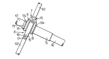
図3から7から詳細に分かるように、ピストン式の各ダンパ6の第1の連結部7は、それに対応する控えの周りに取り付けられているスチール製のカラー9と、このカラー9をピストンダンパ6に、すなわち、より具体的には、ピストン式の当該ダンパ6のピストンボディ61に直接連結されている金属製のチューブ62に連結するピボット連結部10を有している。
As can be seen in detail from FIGS. 3 to 7, the first connecting part 7 of each piston-type damper 6 comprises a
ピボット連結部10は、カラー9から上方に延び、かつ、相互に向かい合って控えの軸線に直角な軸線に沿って配置されている2つの孔がそれぞれ形成されている2つのフランジ10aを有する雌型のヨークの形態を取っている。ピストン式のダンパ6の金属製のチューブ62は、それ自体、雌型のヨークの2つのフランジ10aの間に配置される雄型のヨーク11の形態を取っている端部を有し、雄型のこのヨーク11は、同様に、雌型のヨークの孔と相互に対応するように配置された孔を備えている。雄型のヨークと雌型のヨークは、控えの軸線に直角に延びているピン12によって相互に連結されている。
The pivot joint 10 is a female type having two
ここで考慮されている例において、カラー9は、控えを直接囲む円形の開口を有する2つの平行なフランジ91の形態を取っている。この目的のために、控えは、カラー9が取り付けられるように意図された金属製のチューブ13を備えている。金属製のこのチューブ13を取り付けるために、鞘部材42は切断され、HDPEから作られた2つの部分42aが鞘部材42の2つの切断端にそれぞれ固定されている。これらの2つの部分42aは、それぞれ鞘部材42の厚さより厚い厚さを有し、金属製のチューブ13上に形成された内面ねじと、ねじ込むことによって協同するように意図された外面ねじをそれぞれ備えている。
In the example considered here, the
さらに、くさび部材14が、同様に、金属製のチューブ13を2つの部分42a上にねじ込む前に、鞘部材42の内側に直接取り付けられている。このくさび部材14の機能は、金属製の撚り線41を2つの部分42aに対して遊びを最小限にして締め付けることである。このくさび部材14が取り付けられた後、金属製のチューブ13は、2つの部分42a上にねじ込まれ、そして最後に、例えば、溶接によって固定される。
Further, the
カラー9、すなわち、より正確には、その2つのフランジ91は、その後、金属製のチューブ13に取り付けることができる。
The
カラー9が、建造物が運用されるようになる前に金属製のチューブ13に取り付けられる場合、フランジ91は、対応する控えの一端の所ではめ込み、その後、金属製のチューブ13まで並進運動させて移動させることができる。それとは反対に、カラー9が、建造物が運用されるようになった後に金属製のチューブ13に取り付けられる場合、各フランジ91は、ピボット10と一体に製作された第1の半円筒状の半フランジと第2の半円筒状のフランジによって形成することができる。これらの2つの半フランジは、その後、金属製のチューブ13の周りに取り付けられ、次に、カラー9を形成するために、例えばねじで止めることによって相互に固定される。
If the
カラー9の2つのフランジ91は、次に、2つのフランジ91の両側に配置された2つの止め具13aによって、金属製のチューブ13上における並進運動に関してブロックされる。これらの止め具は、円筒形のチューブ13に取り付け、直接溶接することができる。
The two
ピストン式の各ダンパ6の第2の連結部8は、同様に、当該ダンパ6に対応する控えの周りに取り付けられたスチール製のカラー15と、カラー15を、ピストン式のこのダンパ6に連結するピボット連結部16を有している。ピボット連結部16は、同様に、カラー15から下方に延び、相互に向かい合って控えの軸線に直角な軸線に沿って配置された2つの孔がそれぞれ形成された2つのフランジ16aを有する雌型のヨークの形態を取っている。ピストン式のダンパ6のピストン63は、それ自体が、雌型のヨークの2つのフランジ16aの間に配置された雄型のヨーク17の形態を取っている端部を有し、雄型のこのヨーク17は、同様に、雌型のヨークの両孔と対応するように配置された孔を有している。雄型のヨークと雌型のヨークは、控えの軸線に直角に延びるピン18によって相互に連結されている。
Similarly, the second connecting
ここで考慮されている例において、カラー15は、カラー9の2つのフランジ91の間に配置されていた単一のフランジの形態を取っている。このフランジ15は控え、すなわち、より具体的には円筒状のチューブ13を直接囲んでいる円形の開口を有している。カラー15が、金属製のチューブ13に、建造物が運用されるようになる前に取り付けられるか、後に取り付けられるかに依存して、カラー5は、カラー9に関して上述したように、1つの部品として形成し、または2つの部品として形成することができる。
In the example considered here, the
したがって、第1および第2の連結部7および8のカラー9および15は、それらが取り付けられている控えを完全に取り囲み、同時に、当該控えの軸線と、複数の控えを含む平面にのみ直角なピボット軸線を有するピボット連結部10または16によってピストン式のダンパ6に連結されている。したがって、ピストン式の各ダンパによって加えられる力は、カラー9または15によって円筒状のチューブ13に対して、その中心、すなわち、対応する控えの断面の重心に加えられ、その結果、当該複数の控えの少なくとも1つのねじれを生じさせる可能性がある幾何学的な不安定性の恐れも回避される。勿論、金属製のチューブ13は、カラー9とカラー15の間に生じる剪断力に耐えることができなければならない。
Thus, the
ダンパ6が控えの鉛直方向の変位のみを減衰させるように意図されている場合、カラー9と15は、金属製のチューブ13の周りの回転に関して自由度が全くない状態で金属製のチューブ13の周りに直接取り付けられていてよい。代替の他の実施形態によれば、カラー9および15は、図6および7に示されているように、適切な潤滑剤によって金属製のチューブ13の周りに最小限の摩擦を伴ってピボット運動できるように取り付けられていてよい。この場合、第1、第2の連結部7、8の各々は、対応する控えの軸線に直角なピボット連結部10、16、および、チューブ13と各カラーによって形成され、対応する控えの軸線と中心を合わされ、この軸線と平行な他のピボット連結部によって形成されている。
If the damper 6 is intended to dampen only the vertical displacement of the reserve, the
カラー9および15が最小限の摩擦を伴ってチューブ13の周りをピボット運動できるように取り付けられている場合、したがって、第1、第2の連結部7、8の各々は、ボール・ジョイント連結と同様の2つの自由度を備える2つのピボット軸を、それによって、本実施形態において、ピストン式の各ダンパによって加えられる力がもはや対応する控えの断面の重心に加えられないということに対応する幾何学的な不安定性を引き起こす、ボール・ジョイント連結の欠点を生じることなく有している連結部を形成している。
If the
さらに、控えの、1組の控えを含む平面に直角な平面内における横方向の振動を減衰させることも有利であることが分かる場合もある。 In addition, it may prove advantageous to damp lateral vibrations in a plane perpendicular to the plane containing the set of copies.
この目的のために、金属製のチューブとカラー9、15の間の調整された摩擦力によって控えの横方向の変位を回転運動の減衰の形態で減衰(rotational damping)させることができるように、第1および第2の連結部7および8のカラー9および15は所定の摩擦係数を伴ってピボット運動するように金属製のチューブ13に取り付けられる。この目的のために、カラー9および15の円形の開口の内壁と金属製のチューブ13の外壁は、材料の適切な選択によって摩擦力が制御される摩擦面を有するように変更してもよい。カラー9および15と金属製のチューブ13の間に直接挿入された適切な摩擦ライニングの存在によって、回転運動の減衰の形態の減衰によって、同様に、控えの横方向の変位を制限することが可能になる。接触する材料は、「メタロプラスト」のような、長持ちする耐摩耗の特性を有し、長期間に亘って一定の摩擦係数を保証しなければならない。
For this purpose, the adjusted lateral force between the metal tube and the
図8は、カラー15と、控えと一体の金属製のチューブ13の間の回転運動の減衰によって控えの横方向の振動を制限するための、金属製のチューブ13とカラー15の間のピボット連結部の他の実施形態を示している。
FIG. 8 shows a pivot connection between the
このカラー15は、金属製のチューブ13上にピボット運動できるように取り付けられ、調節可能な締め付け機構19によって相互に連結された自由な2つの端部15a、15bを有する、開いたカラーの形態を取っている。この調節可能な締め具機構19は、カラー15の、金属性のチューブ13に対する締め付けを調整するために、端部15a、15bを相互に近づけるように作用する、例えば、ばね機構、ベレビルワッシャ機構、またはジャッキの形態を取っていてよい。この締付けの調整によって、カラー15の内面と円筒形のチューブ13の外面の間の摩擦係数を変え、したがって、単一の控え、またはピストン式のダンパ6によって相互に連結された複数の控えの横方向の減衰を変えることができる。
This
もちろん、カラー15のこの実施形態は、カラー9のフランジ91に対しても使用することができる。
Of course, this embodiment of the
カラー9および15と金属製のチューブ13の間に、調整された摩擦を設定する代わりに、他のエネルギー消散プロセスを、控えの横方向の変位を減衰させるのに用いることもできる。例えば、ピストン式のダンパ6を第1および第2の連結部に連結する金属製のチューブ62が、控えの横方向の変位の際に変形するように、慣性を制御された部分(controlled-inertia section)を有するようにすることができる。正確に言うと、塑性の範囲で湾曲させられる金属製の棒の変形は、エネルギーの消散を伴うことが知られている。
Instead of setting a conditioned friction between the
ダンパを、それらの第1、第2の連結部に連結する金属製のチューブまたは棒の変形を含む、代替のこの実施形態は、カラー9および15がチューブ13に対して固定されて取り付けられているときに用いられる。
This alternative embodiment, which includes a deformation of the metal tube or bar connecting the dampers to their first and second connections, has the
Claims (9)
前記第1の控え(4a)にリンク連結されている第1の連結部(7)と、前記第2の控え(4b)にリンク連結されている第2の連結部(8)を有し、実質的に線形のストロークを備え、前記第1の控え(4a)と前記第2の控え(4b)とを連結する少なくとも1つのダンパ(6)を有し、前記ダンパ(6)のストロークが前記第1および第2の控え(4a、4b)に実質的に直角であるように前記ダンパ(6)の軸が前記第1および第2の控え(4a、4b)に直角であり、前記ダンパ(6)は、ピストンボディ(61)と、該ピストンボディ(61)に対して可動に取り付けられているピストン(63)と、を有し、前記ピストンボディ(61)は前記リンク連結されている第1の連結部(7)を備え、前記ピストン(63)は前記リンク連結されている第2の連結部(8)を備えていることを特徴とする装置。 A sheet having a plurality of cable stays of the bridge (1), wherein the sheet has at least one first stay (4a) and one second structure configured in one plane including the bridge deck and the steel tower. In the device for attenuating the vibration of the sheet (4) having the storage (4b),
A first connecting part (7) linked to the first hook (4a) and a second connecting part (8) linked to the second hook (4b); substantially comprises a linear stroke, the first having 1 to refrain from (4a) and said second copy (4b) at least one damper and you connecting (6), the stroke of the damper (6) There Ri axis said first and second ahead (4a, 4b) perpendicular der of the first and second copy (4a, 4b) said damper so as to be substantially perpendicular to (6), The damper (6) includes a piston body (61) and a piston (63) that is movably attached to the piston body (61), and the piston body (61) is linked to the link. A first connecting portion (7), wherein the piston (63) Optionally and wherein the Rukoto comprises second connecting portion that is click connecting (8).
それに対応する前記控えの周囲に取り付けられているカラー(9、15)と、
該カラー(9、15)を前記ダンパ(6)に連結するピボット連結部(10、16)を有する、請求項1に記載の装置。 Each of the first and second connecting portions (7, 8)
A collar (9, 15) attached to the periphery of the corresponding copy;
The device according to claim 1, comprising a pivot connection (10, 16) for connecting the collar (9, 15) to the damper (6).
振動の減衰が、請求項1から8のいずれか1項に記載の装置(6)によって行われることを特徴とする方法。
A sheet having a plurality of stays of the bridge (1), wherein at least one first stay (4a) and one second stay (in a plane including the bridge deck and the steel tower) 4b) in a method for dampening vibration of a sheet (4),
Method according to claim 1, characterized in that the damping of vibrations is performed by the device (6) according to any one of claims 1-8 .
Applications Claiming Priority (1)
| Application Number | Priority Date | Filing Date | Title |
|---|---|---|---|
| FR0313240A FR2862073B1 (en) | 2003-11-12 | 2003-11-12 | DEVICE FOR DAMPING THE VIBRATION OF A HAUBANS TAB OF A CONSTRUCTION WORK AND METHOD OF DAMPING THE SAME |
Publications (3)
| Publication Number | Publication Date |
|---|---|
| JP2005146837A JP2005146837A (en) | 2005-06-09 |
| JP2005146837A5 JP2005146837A5 (en) | 2007-05-24 |
| JP4504716B2 true JP4504716B2 (en) | 2010-07-14 |
Family
ID=34508408
Family Applications (1)
| Application Number | Title | Priority Date | Filing Date |
|---|---|---|---|
| JP2004098535A Expired - Fee Related JP4504716B2 (en) | 2003-11-12 | 2004-03-30 | Apparatus for damping vibrations of a plurality of sheets of a building and a damping method corresponding thereto |
Country Status (5)
| Country | Link |
|---|---|
| US (1) | US7631384B2 (en) |
| JP (1) | JP4504716B2 (en) |
| FR (1) | FR2862073B1 (en) |
| MY (1) | MY141276A (en) |
| WO (1) | WO2005049923A1 (en) |
Families Citing this family (24)
| Publication number | Priority date | Publication date | Assignee | Title |
|---|---|---|---|---|
| US7797892B2 (en) * | 2007-02-09 | 2010-09-21 | Buildings And Matters, Llc | Kit for plugging a hole with a fire resistant material |
| DE102007017697A1 (en) | 2007-04-14 | 2008-10-23 | Dywidag-Systems International Gmbh | Tension member for structures and method for its production |
| CN101709567B (en) * | 2009-10-14 | 2011-05-18 | 中铁大桥局集团武汉桥梁科学研究院有限公司 | Mass damping device of rigid connection space lever of stay cable |
| RU2533410C2 (en) * | 2010-03-26 | 2014-11-20 | Фсл Интернациональ Аг | Perfection of guide for strands |
| RU2462548C2 (en) | 2010-05-12 | 2012-09-27 | Солетанш Фрейсине | Method to damp vibrations of guy cable and appropriate system |
| CN102494077B (en) * | 2011-12-08 | 2013-06-12 | 中联重科股份有限公司 | Vibration reduction system and vibration reduction method for coupling vibration of tower crane and cable tower |
| CN102776837B (en) * | 2012-08-13 | 2015-08-26 | 长安大学 | A kind of suspension cable vibration insulating system based on band damping lazy halyard |
| CN103362064B (en) * | 2013-07-04 | 2015-02-18 | 江苏法尔胜缆索有限公司 | Auxiliary cable net system for vibration reduction of extra-large span bridge cables |
| CN103469728B (en) * | 2013-09-25 | 2016-08-24 | 无锡市弘谷振控技术有限公司 | External stayed cable damping device |
| FR3012193B1 (en) * | 2013-10-23 | 2015-12-18 | Soletanche Freyssinet | DEVICE FOR DAMPING THE VIBRATION OF A CABLE |
| FR3012479B1 (en) | 2013-10-31 | 2016-01-01 | Soletanche Freyssinet | CABLES VIBRATION DAMPING DEVICE OF AN ART WORK SUSPENSION SYSTEM |
| CH709002A1 (en) * | 2013-12-18 | 2015-06-30 | Vsl Lnternat Ag | Apparatus and method for friction damping. |
| TWI548796B (en) * | 2013-12-30 | 2016-09-11 | Univ Chienkuo Technology | Oblique bridge cable vibration dampers |
| CN104404886B (en) * | 2014-11-27 | 2016-02-17 | 湖南科技大学 | Two rope composite damping rope |
| CN104612054B (en) * | 2015-02-13 | 2016-07-06 | 长安大学 | A kind of netted vibration absorbing device for staying cables of bridge |
| FR3033803B1 (en) * | 2015-03-16 | 2021-01-29 | Soletanche Freyssinet | CABLE VIBRATION DAMPING DEVICE |
| CN105463998A (en) * | 2016-01-06 | 2016-04-06 | 柳州东方工程橡胶制品有限公司 | Mounting method for stay cable external shock absorbing device |
| FR3049030B1 (en) * | 2016-03-18 | 2018-08-31 | Soletanche Freyssinet | IMPROVED DEVICE FOR DAMPING THE VIBRATION OF A CABLE, IN PARTICULAR A WASTE CABLE |
| US20190264402A1 (en) | 2016-07-27 | 2019-08-29 | Soletanche Freyssinet | Double-sheathed structural cable |
| MX2019009238A (en) | 2017-02-03 | 2019-09-19 | Soletanche Freyssinet | A structural cable having an inner housing. |
| CN107893368A (en) * | 2017-11-13 | 2018-04-10 | 安徽省交通控股集团有限公司 | Large span floating system cable stayed bridge provided with inclined type bridge earthquake resistance damper |
| EP4158105A1 (en) * | 2020-05-27 | 2023-04-05 | DYWIDAG-Systems International GmbH | Damping arrangement for a cable |
| CN113175495B (en) * | 2021-04-25 | 2023-01-10 | 中建七局第四建筑有限公司 | Stay cable damping device and installation method |
| CN116180583B (en) * | 2023-04-24 | 2023-07-14 | 湖南省潇振工程科技有限公司 | Ball screw type eddy current damping stay cable vibration damper |
Citations (6)
| Publication number | Priority date | Publication date | Assignee | Title |
|---|---|---|---|---|
| DE3343352C1 (en) * | 1983-11-30 | 1985-06-05 | Max 8228 Freilassing Aicher | Composite cable for prestressed concrete constructions, preferably for cable-stayed bridges |
| JPH0350609U (en) * | 1989-09-25 | 1991-05-16 | ||
| JPH1060816A (en) * | 1996-08-26 | 1998-03-03 | Bridgestone Corp | Cable vibration control device |
| JPH10195818A (en) * | 1997-01-17 | 1998-07-28 | Kawada Kogyo Kk | Cable damping device for cable stayed bridge |
| JPH11350429A (en) * | 1998-06-05 | 1999-12-21 | Sumitomo Rubber Ind Ltd | Displacement restricting device of parallel cables |
| JP2001254312A (en) * | 2000-03-10 | 2001-09-21 | Ohbayashi Corp | Vibration control device for cable-stayed bridge cable |
Family Cites Families (10)
| Publication number | Priority date | Publication date | Assignee | Title |
|---|---|---|---|---|
| US3463870A (en) * | 1968-02-14 | 1969-08-26 | Preformed Line Products Co | Spacer/damper |
| BE754741A (en) * | 1969-08-14 | 1971-01-18 | Burndy Corp | CABLE SHOCK ABSORBER FOR TRANSMISSION LINES |
| IT962511B (en) * | 1972-08-03 | 1973-12-31 | Cantamessa L | SPACER FOR BANDS OF CONDUCTORS FOR AERIAL POWER LINES |
| FR2631407A1 (en) | 1988-05-16 | 1989-11-17 | Freyssinet Int Stup | IMPROVEMENTS TO DEVICES FOR DAMPING THE VIBRATING OF THE STAYS |
| JPH0350609A (en) | 1989-07-19 | 1991-03-05 | Hitachi Ltd | Controller for robot |
| FR2664920B1 (en) | 1990-07-19 | 1992-10-30 | Freyssinet Int Stup | IMPROVEMENTS IN OR RELATING TO DEVICES FOR DAMPING THE VIBRATIONS OF THE STAYS. |
| EP1013830A1 (en) * | 1998-12-24 | 2000-06-28 | Freyssinet International Stup | Device and process for fastening a building element and a cable structure and suspension bridge having such devices |
| US6292967B1 (en) * | 1999-09-14 | 2001-09-25 | Construction Technology Laboratories, Inc. | TMD-damped stay cable and method and TMD |
| FR2806106B1 (en) * | 2000-03-13 | 2002-10-11 | Freyssinet Int Stup | ADJUSTABLE ANCHOR FOR A CABLE CARRYING A CIVIL ENGINEERING STRUCTURE COMPRISING SUCH ANCHORAGES, AND METHOD FOR ADJUSTING SUCH ANCHORING |
| FR2832479B1 (en) * | 2001-11-19 | 2006-05-26 | Maurer Friedrich Soehne | DAMPING DEVICE FOR CABLE |
-
2003
- 2003-11-12 FR FR0313240A patent/FR2862073B1/en not_active Expired - Fee Related
-
2004
- 2004-03-30 JP JP2004098535A patent/JP4504716B2/en not_active Expired - Fee Related
- 2004-11-08 MY MYPI20044636A patent/MY141276A/en unknown
- 2004-11-09 US US10/578,818 patent/US7631384B2/en not_active Expired - Fee Related
- 2004-11-09 WO PCT/FR2004/002880 patent/WO2005049923A1/en active Application Filing
Patent Citations (6)
| Publication number | Priority date | Publication date | Assignee | Title |
|---|---|---|---|---|
| DE3343352C1 (en) * | 1983-11-30 | 1985-06-05 | Max 8228 Freilassing Aicher | Composite cable for prestressed concrete constructions, preferably for cable-stayed bridges |
| JPH0350609U (en) * | 1989-09-25 | 1991-05-16 | ||
| JPH1060816A (en) * | 1996-08-26 | 1998-03-03 | Bridgestone Corp | Cable vibration control device |
| JPH10195818A (en) * | 1997-01-17 | 1998-07-28 | Kawada Kogyo Kk | Cable damping device for cable stayed bridge |
| JPH11350429A (en) * | 1998-06-05 | 1999-12-21 | Sumitomo Rubber Ind Ltd | Displacement restricting device of parallel cables |
| JP2001254312A (en) * | 2000-03-10 | 2001-09-21 | Ohbayashi Corp | Vibration control device for cable-stayed bridge cable |
Also Published As
| Publication number | Publication date |
|---|---|
| MY141276A (en) | 2010-04-16 |
| JP2005146837A (en) | 2005-06-09 |
| FR2862073B1 (en) | 2007-11-23 |
| US7631384B2 (en) | 2009-12-15 |
| FR2862073A1 (en) | 2005-05-13 |
| US20070061982A1 (en) | 2007-03-22 |
| WO2005049923A1 (en) | 2005-06-02 |
Similar Documents
| Publication | Publication Date | Title |
|---|---|---|
| JP4504716B2 (en) | Apparatus for damping vibrations of a plurality of sheets of a building and a damping method corresponding thereto | |
| EA021188B1 (en) | Multi-directional torsional hysteretic damper | |
| KR102263498B1 (en) | Device for damping vibrations in a cable | |
| RU2462548C2 (en) | Method to damp vibrations of guy cable and appropriate system | |
| US6226935B1 (en) | Seismic isolator | |
| US10934734B1 (en) | Damped reinforced joint for beam-column connection | |
| EP0825301B1 (en) | Cable damping device | |
| KR101273641B1 (en) | Device for damping the vibrations of a cable and related damping method | |
| JP2019508622A (en) | Wind generator with elastic ball / pendulum bearing | |
| KR101530643B1 (en) | Saddle for main tower of bridge and cable anchoring method therewith | |
| JP4335151B2 (en) | Civil engineering structure cable | |
| JP4669572B1 (en) | Cable-type falling bridge prevention structure and cable-type falling bridge prevention device | |
| CN113373802B (en) | Shock attenuation expansion joint based on wire rope attenuator | |
| JP3866175B2 (en) | Articulated bridge protection device | |
| CN217460234U (en) | Anchoring device, carbon fiber beam connecting device and beam-platform connecting structure | |
| JP5291334B2 (en) | Fall prevention device | |
| JPH10183531A (en) | Connecting member for bridge fall preventing device, its anchoring method, and bridge fall preventing device utilizing it | |
| KR102701025B1 (en) | An equipment for connecting profiles | |
| EP4118360B1 (en) | Cable bending limiting arrangement and combination of a cable bending limiting arrangement with a cable, an anchorage, a compacting clamp unit and a recess pipe | |
| KR200494644Y1 (en) | Dummy structure for clamping steel strand | |
| CN220452099U (en) | Dragline system, tower assembly and wind generating set | |
| CN215714562U (en) | Pendulum type multidirectional multiple-tuning mass damper | |
| CN117005319A (en) | Short jib longitudinal bridge direction skew adjusting device | |
| JP5849168B1 (en) | Suspension structure of road equipment | |
| KR19990020725U (en) | Failing device |
Legal Events
| Date | Code | Title | Description |
|---|---|---|---|
| A521 | Written amendment |
Free format text: JAPANESE INTERMEDIATE CODE: A523 Effective date: 20070329 |
|
| A621 | Written request for application examination |
Free format text: JAPANESE INTERMEDIATE CODE: A621 Effective date: 20070329 |
|
| A131 | Notification of reasons for refusal |
Free format text: JAPANESE INTERMEDIATE CODE: A131 Effective date: 20090512 |
|
| A521 | Written amendment |
Free format text: JAPANESE INTERMEDIATE CODE: A523 Effective date: 20090805 |
|
| A131 | Notification of reasons for refusal |
Free format text: JAPANESE INTERMEDIATE CODE: A131 Effective date: 20091209 |
|
| A521 | Written amendment |
Free format text: JAPANESE INTERMEDIATE CODE: A523 Effective date: 20100304 |
|
| TRDD | Decision of grant or rejection written | ||
| A01 | Written decision to grant a patent or to grant a registration (utility model) |
Free format text: JAPANESE INTERMEDIATE CODE: A01 Effective date: 20100331 |
|
| A01 | Written decision to grant a patent or to grant a registration (utility model) |
Free format text: JAPANESE INTERMEDIATE CODE: A01 |
|
| A61 | First payment of annual fees (during grant procedure) |
Free format text: JAPANESE INTERMEDIATE CODE: A61 Effective date: 20100423 |
|
| R150 | Certificate of patent or registration of utility model |
Ref document number: 4504716 Country of ref document: JP Free format text: JAPANESE INTERMEDIATE CODE: R150 Free format text: JAPANESE INTERMEDIATE CODE: R150 |
|
| FPAY | Renewal fee payment (event date is renewal date of database) |
Free format text: PAYMENT UNTIL: 20130430 Year of fee payment: 3 |
|
| FPAY | Renewal fee payment (event date is renewal date of database) |
Free format text: PAYMENT UNTIL: 20140430 Year of fee payment: 4 |
|
| R250 | Receipt of annual fees |
Free format text: JAPANESE INTERMEDIATE CODE: R250 |
|
| R250 | Receipt of annual fees |
Free format text: JAPANESE INTERMEDIATE CODE: R250 |
|
| R250 | Receipt of annual fees |
Free format text: JAPANESE INTERMEDIATE CODE: R250 |
|
| R250 | Receipt of annual fees |
Free format text: JAPANESE INTERMEDIATE CODE: R250 |
|
| R250 | Receipt of annual fees |
Free format text: JAPANESE INTERMEDIATE CODE: R250 |
|
| R250 | Receipt of annual fees |
Free format text: JAPANESE INTERMEDIATE CODE: R250 |
|
| R250 | Receipt of annual fees |
Free format text: JAPANESE INTERMEDIATE CODE: R250 |
|
| R250 | Receipt of annual fees |
Free format text: JAPANESE INTERMEDIATE CODE: R250 |
|
| LAPS | Cancellation because of no payment of annual fees |