JP4335151B2 - Civil engineering structure cable - Google Patents
Civil engineering structure cable Download PDFInfo
- Publication number
- JP4335151B2 JP4335151B2 JP2004564059A JP2004564059A JP4335151B2 JP 4335151 B2 JP4335151 B2 JP 4335151B2 JP 2004564059 A JP2004564059 A JP 2004564059A JP 2004564059 A JP2004564059 A JP 2004564059A JP 4335151 B2 JP4335151 B2 JP 4335151B2
- Authority
- JP
- Japan
- Prior art keywords
- cable
- guide member
- reinforcing
- anchor device
- anchor
- Prior art date
- Legal status (The legal status is an assumption and is not a legal conclusion. Google has not performed a legal analysis and makes no representation as to the accuracy of the status listed.)
- Expired - Lifetime
Links
Images


Classifications
-
- E—FIXED CONSTRUCTIONS
- E01—CONSTRUCTION OF ROADS, RAILWAYS, OR BRIDGES
- E01D—CONSTRUCTION OF BRIDGES, ELEVATED ROADWAYS OR VIADUCTS; ASSEMBLY OF BRIDGES
- E01D19/00—Structural or constructional details of bridges
- E01D19/14—Towers; Anchors ; Connection of cables to bridge parts; Saddle supports
Abstract
Description
本発明は、特定の土木工学構造物の構造に関与する建造物に使用されるケーブルの分野に関する。 The present invention relates to the field of cables used in buildings involving the construction of specific civil engineering structures.
本発明は、より詳細には、地震の場合に優れた特性を与えるようなケーブルの配置構成に関するものである。 More particularly, the present invention relates to a cable arrangement that provides superior characteristics in the event of an earthquake.
本発明は、船橋甲板の如き構築の吊り下げ部分に使用される支持ケーブル (stay cable) に特に適用可能である。 The present invention is particularly applicable to stay cables used in suspended parts of construction such as bridge decks.
そのような支持ケーブルは、現在の形態では、2つのアンカー領域間、すなわち建造物のパイロン上に配された一方の領域と吊り下げ部における他方の領域との間に、一束の並行補強部材を備える。このアンカー領域では、支持ケーブルの個々の補強部材は、それぞれが個別にロックされるように僅かに分岐している。 Such a support cable, in its present form, is a bundle of parallel reinforcing members between two anchor regions, i.e. between one region arranged on the pylon of the building and the other region in the suspension. Is provided. In this anchor region, the individual reinforcing members of the support cable are slightly branched so that each is individually locked.
固定された建造物が地震を受けた場合、懸架された部分(例えば船橋甲板)は、パイロンに対し、突発的で潜在的に大きな変位を受ける。この結果、支持ケーブルは、引張り及び屈曲に関して高い変動を生ずる。 When a fixed building is subjected to an earthquake, the suspended part (eg, the bridge deck) is subject to sudden and potentially large displacement relative to the pylon. As a result, the support cable is subject to high fluctuations with respect to tension and bending.
曲げ応力はアンカー領域で反射し、かつ補強部材及び/又はアンカー装置を破損するおそれがある。 Bending stresses are reflected at the anchor region and can damage the reinforcement member and / or the anchor device.
特許文献1は、構造体ケーブルのためのアンカー装置を開示している。このアンカー装置は、各補強部材のための個々のガイドダクトを備えたガイド手段を有する。このダクトは、ケーブルのランニング部 (running part) の方向に広くなっており、そのため補強部材の角度偏差が許容されるようになっている。このアンカー装置の利点は、ランニング部に向かう補強部材の収束に起因する曲げ力、又は支持ケーブルによって生ずる横方向(長手方向と直交する方向)の動き、を取り除くということである。しかしながら、そのような力の除去は、地震時に生じる猛烈な応力変化の存在した状態では不十分であると分かるであろう。
本発明の目的は、構造体ケーブル (structure cable) 及びこれら構造体ケーブルによって一部が構成される建造物が、地震の場合に生じる高い応力に耐えられるようにする構成を提案することである。 It is an object of the present invention to propose a structure that allows structure cables and structures partly constituted by these structure cables to withstand the high stresses that occur in the event of an earthquake.
従って本発明は、
一組の引張り補強部材 (traction reinforcement) ;
補強部材を建造物の二つのそれぞれにアンカー留めするための二つの装置であり、補強部材がこれらアンカー装置において互いに離間しているアンカー装置;及び、
補強部材をケーブルのランニング部に向けて収束させ、アンカー装置においてよりコンパクトとなるよう実質的に平行な束となす、補強部材を偏向させるための手段;
を備えてなる土木工学構造体ケーブルを提案するものである。
Therefore, the present invention
A set of traction reinforcements;
Two devices for anchoring the reinforcing members to each of the two of the building, wherein the reinforcing members are spaced apart from each other in the anchor devices; and
Means for deflecting the reinforcing member, converging the reinforcing member towards the running part of the cable and forming a substantially parallel bundle for more compactness in the anchoring device;
A civil engineering structure cable comprising:
本発明によれば、構造体ケーブルは少なくとも1つのガイド部材を備える。ガイド部材は、補強部材の組の回りに密着してセットされるもので、内面を有している。この内面の横断面は並行するバンドル(束)の外周形状に適合し、かつ縦断面は凸の曲率を有している。この曲率は、該ガイド部材の長さにわたって補強部材に角度偏向を与える。その偏向角度は、実質的に、アンカー装置とケーブルのランニング部との間の補強部材の最大収束角度よりも大きい。 According to the invention, the structural cable comprises at least one guide member. The guide member is set in close contact with the set of reinforcing members and has an inner surface. The cross section of the inner surface is adapted to the outer peripheral shape of parallel bundles, and the vertical section has a convex curvature. This curvature imparts angular deflection to the reinforcing member over the length of the guide member. The deflection angle is substantially larger than the maximum convergence angle of the reinforcing member between the anchor device and the running part of the cable.
ガイド部材の形成により、補強部材及びアンカー装置にダメージを受けないように、制御された曲率半径によって補強部材の組の角度偏向が吸収される。 By forming the guide member, the angular deflection of the set of reinforcing members is absorbed by the controlled radius of curvature so that the reinforcing member and the anchor device are not damaged.
本発明によるケーブルの好ましい実施例では、
ガイド部材によって許容される角度の偏差は少なくとも100ミリラジアンであり;
ガイド部材によって許可される角度の偏差は、アンカー装置とケーブルのランニング部と間の補強部材の最大収束角の少なくとも2倍であり;
ガイド部材の内面の縦断面の曲率半径は、該ガイド部材が補強部材の組の回りに密着した部分において少なくとも3メートルであり;
ガイド部材の内面の縦断面の曲率半径は、該部材が補強部材の組の回りに密着している部分からケーブルのランニング部に向かって減少し;
ガイド部材は、アンカーのうちの1つ対し、横方向(長手方向と直交する方向)の動きを許容するように取り付けられ;
アンカー装置の一つに対して補強部材の束の横方向振動を減衰させるダンパー手段が設けられて、かつ、ガイド部材は、補強部材の組における前記ダンパー手段とアンカー装置との間に位置され;
ガイド部材は、ダンパー手段のストロークを規定するために、前記アンカー装置に対し、横方向の動きが制限されるように取り付けられ;
アンカー装置は、チューブに長手方向に支持される。チューブは建造物の一部の構造体に接続され、該チューブを介して補強部材が通され、かつ前記ダンパー手段は、補強部材の束と、前記チューブのアンカー装置とは反対側の端部に取り付けられたサポートとの間に配されたダンパを備え、さらに前記チューブの端部への前記サポートの取付けは、所定のしきい値を超えた力が付与された場合には破壊するように構成された接続によってなされ;
偏向手段は、アンカー装置から所定寸法離れて補強部材の組のまわりに留められたカラーを備え、かつガイド部材は、補強部材の組における前記カラーと前記アンカー装置との間に置かれ;
ガイド部材内部の補強部材間に間隙を維持するために、ガイド部材と共に、複数のインサートがガイド部材内に取り付けられ;
前記インサートは、好ましくは六角形断面の内面を備えたガイド部材の内部の補強部材のまわりに個々に配置されたプラスチックスリーブを備え;
ガイド部材は、偏向装置に属し、同時に、補強部材をケーブルのランニング部に向け収束させる機能も有し;
ガイド部材は、金属製補強チューブの回りに成形プラスチック樹脂の本体を供え、かつこのプラスチック樹脂は特にポリウレタン樹脂であってよい。
In a preferred embodiment of the cable according to the invention,
The angular deviation allowed by the guide member is at least 100 milliradians;
The angular deviation allowed by the guide member is at least twice the maximum convergence angle of the reinforcing member between the anchoring device and the running part of the cable;
The radius of curvature of the longitudinal section of the inner surface of the guide member is at least 3 meters at the portion where the guide member is in intimate contact with the set of reinforcing members;
The radius of curvature of the longitudinal section of the inner surface of the guide member decreases from the portion where the member is in intimate contact around the set of reinforcing members toward the running portion of the cable;
A guide member is attached to one of the anchors to allow lateral movement (direction perpendicular to the longitudinal direction);
Damper means for damping lateral vibration of the bundle of reinforcing members is provided for one of the anchor devices, and the guide member is located between the damper means and the anchor device in the set of reinforcing members;
A guide member is attached to the anchor device such that lateral movement is restricted to define a stroke of the damper means;
The anchor device is supported longitudinally on the tube. The tube is connected to a part of the structure of the building, the reinforcing member is passed through the tube, and the damper means is attached to the bundle of the reinforcing member and the end of the tube opposite to the anchor device. A damper disposed between the attached support and the attachment of the support to the end of the tube configured to break if a force exceeding a predetermined threshold is applied Made by a connected connection;
The deflecting means comprises a collar that is clamped around the set of reinforcing members a predetermined distance away from the anchor device, and a guide member is placed between the collar and the anchor device in the set of reinforcing members;
A plurality of inserts are mounted within the guide member along with the guide member to maintain a gap between the reinforcing members within the guide member;
Said inserts comprise plastic sleeves individually arranged around the reinforcing member inside the guide member, preferably with an inner surface of hexagonal cross section;
The guide member belongs to the deflection device and at the same time has the function of converging the reinforcing member toward the running part of the cable;
The guide member provides a body of molded plastic resin around the metal reinforcing tube, and this plastic resin may in particular be a polyurethane resin.
本発明の他の態様は、上述した如き構造体ケーブルのためのガイド部材に関するものである。この部材は、管状の一般的な形状を有し、その内面は一組の引張り補強部材の回りに密着する。この一組の引張り補強部材はアンカー装置とケーブルのランニング部との間で収束している。そこにおいて、補強部材は集まって並行な束とされ、該束はアンカー装置における部分よりもコンパクトなものとなっている。前記内面は前記束の外周形状に適合した断面を有し、かつ縦断面は凸面の曲率を有する。その曲率は、ガイド部材の長さにわたって補強部材の角度偏向を許容するもので、該角度は、アンカー装置とケーブルのランニング部との間の補強部材の最大収束角度よりも実質的に大きいものである。前記内面は好ましくは六角形円形の断面図を有している。 Another aspect of the present invention relates to a guide member for a structural cable as described above. This member has a general tubular shape, and its inner surface is closely attached around a set of tensile reinforcement members. This set of tension reinforcing members converges between the anchor device and the running portion of the cable. There, the reinforcing members gather together into a parallel bundle, which is more compact than the portion of the anchor device. The inner surface has a cross section adapted to the outer peripheral shape of the bundle, and the vertical cross section has a convex curvature. The curvature allows the angular deflection of the reinforcing member over the length of the guide member, which is substantially greater than the maximum convergence angle of the reinforcing member between the anchoring device and the cable running portion. is there. The inner surface preferably has a hexagonal circular cross section.
本発明の他の特徴及び優位点は、添付の図面を参照した下記の非限定的実施例の説明により明らかとされる。 Other features and advantages of the present invention will become apparent from the following description of non-limiting examples with reference to the accompanying drawings.
以下、本発明について、橋梁支持ケーブルを構成する構造体ケーブルを例に説明する。ただし、本発明はこの実施例に限定されるものではない。 Hereinafter, the present invention will be described by taking a structure cable constituting a bridge support cable as an example. However, the present invention is not limited to this embodiment.
図1には斜張橋 (cable stayed bridge) を概略で示してある。該斜張橋のデッキ1は、該デッキが通過する領域に立設された少なくとも一つのパイロン3に、複数の組の支持ケーブル2によって支持されている。各支持ケーブル2は、デッキ1に取り付けられた底部アンカー装置4と、パイロン3に取り付けられた頂部アンカー装置5との間に定まった経路を描く。
Figure 1 shows a schematic of a cable stayed bridge. The cable-stayed bridge deck 1 is supported by a plurality of sets of support cables 2 on at least one
図2は、アンカー装置4が位置するデッキ領域における支持ケーブルの構造をより詳細に示している。 FIG. 2 shows in more detail the structure of the support cable in the deck area in which the anchor device 4 is located.
支持ケーブル2は複数本の引張り補強部材10からなる組を備える。各引張り補強部材は、本実施例では、個々のプラスチック製シースによってそれぞれカバーされた金属製のストランド(撚り線)から成る。支持ケーブルのランニング部、すなわちデッキとパイロンとの間のコースに渡って延在する大部分を占める部分においては、各トスランド10は、集められ、コンパクトな並行バンドルとされている。図5には、ランニング部における各ストランド10の断面配置の一例を示してある。ここでは、円形の外形を有した各ストランドが六角形網 (hexagonal meshwork) に従って互いに接触しているため、最大限のコンパクト化が実現されている。
The support cable 2 includes a set of a plurality of
ストランドのこのコンパクトな束(バンドル)を構成するために、アンカー4から離れて配置された偏向カラー11が、ストランドの組の回りに密着状態に取り付けられ、ストランドを収束させる。 In order to form this compact bundle of strands, a deflection collar 11 arranged away from the anchor 4 is attached in close contact around the strand set to converge the strands.
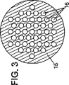
アンカー装置4は、図3に断面で示されるように、金属ブロック15を備える。該ブロック15は、自身を貫通する複数の並列オリフィス16を有している。これらオリフィス16は、支持ケーブルのランニングに向けては円筒状を呈し、かつその反対方向に向けては円錐台状とされている。各オリフィス16は裸撚り線及びアンカージョー (anchoring jaw) を受けている。アンカージョーはコーン型円錐台形の一部の形状をした複数のキーから構成されている。これらオリフィス16は、それらアンカージョーを収納するための余地を提供しかつ十分堅固なブロックを得ために、互いのオリフィス間にある間隔を有している。これらのオリフィスの網目状断面配置は、ケーブルのランニング部におけるストランドの断面配置と相似形である。従って、各ストランドはアンカー装置4からランニング部に向けて収束する。これらのオリフィスの網目状断面配置は、ケーブルのランニング部におけるストランドの断面配置と相似形である。従って、各ストランドはアンカー装置4からランニング部に向けて収束する。
The anchor device 4 includes a
ストランド10の個別のシースは、アンカーブロック15の後部において、チャンバ17内で中断されている。前記ブロック及びチャンバ17の残りのギャップには、グリースのような腐食防止材料が充填される。シールシステム18が、各ストランド10の個々のシースの周囲にシールを形成することにより、ブロック15の反対側でチャンバ17を閉塞している。シールシステム18は、例えば欧州特許第0323285号明細書に記載されている如きスタッフィングボックス・タイプのものである。アンカー装置4はさらに、国際公開第00/75453号パンフレットに開示されている如きダクトを備えていてもよい。このダクトは、個々のストランドの角度の偏向を許容するよう、ケーブルのランニング部の方向に広がっている。
The individual sheaths of the
アンカー装置4は、支持ケーブル1に引張力を伝達するために、デッキ1又はパイロン3の構造体に接続されたチューブ20に対し長手方向に支持する。
The anchor device 4 supports the
図2に示した支持ケーブルは、振動抑制装置21を装備している。この振動抑制装置21は、デッキ側に、アンカー装置4からの所定距離(数メートル)の所に位置している。該装置21は、チューブ20及びアンカー装置4に対する支持ケーブル2の横振動を減衰させるよう機能する。前記横振動は、橋梁上の交通又は航空力学的な力に関連した動荷重変化に起因するものである。振動抑制装置は、例えば欧州特許第0914521号明細書に開示されたタイプのもので、偏向カラー11と支持チューブ22との間に環状チャンバを有し、チューブ20の端部に取り付けられており、環状チャンバが減衰効果をもたらす粘性材料を有したものである。あるいは、この粘性減衰装置は、支持ケーブルとデッキ1との間に交差方向に延びるアームに取り付けることもできる(欧州特許第0343054号明細書参照)。
The support cable shown in FIG. 2 is equipped with a
従って、支持ケーブルは、構造体に対してストランドの全面的な変位を許容する能力を備えている。アンカー装置4の出口部とカラー11との間のレバーアームは、ダンパー21に、所定の横方向のストロークを与える。このストロークは、角度運動、好ましくはストランドの個々のガイドのためのダクトに関係した角度運動を許容するものである。ダクトは前記アンカー装置の出口部にプリセットされたものである。これらの角度運動の振幅は制限されており、通常は約25ミリラジアンまでである。これよりも偏差を大きくすると、アンカー装置においてそれらに過度の曲率を与え、ストランドを破損するおそれがある。 Thus, the support cable has the ability to allow full displacement of the strand relative to the structure. A lever arm between the outlet of the anchor device 4 and the collar 11 gives the damper 21 a predetermined lateral stroke. This stroke allows angular motion, preferably relative to the ducts for the individual guides of the strand. The duct is preset at the outlet of the anchor device. The amplitude of these angular motions is limited and is usually up to about 25 milliradians. If the deviation is larger than this, the anchor device may give them excessive curvature and break the strands.
ただし、地震の場合には生じる角度の偏差ははるかに高いかもしれない。本発明は、そのような状況にあっても支持ケーブルに耐震特性を与えるために、ストランド10を適所に配設する前に、アンカー装置4とカラー11との間にガイド部材30が装着される。
However, in the case of an earthquake, the resulting angular deviation may be much higher. In the present invention, the
このガイド部材30は、一般的な円筒状形状である。図2及び図4に示すように、鋼製補強チューブ21の周囲に設けられた成形プラスチック樹脂の本体から構成することができる。有利には、成形プラスチックは容易に成形することができるという長所を有するウレタン樹脂でり、それにより、該ガイド部材30を、非常に高い精度で成形でき、かつ優れた機械的抵抗特性(硬度、せん断応力及び引張り応力に対する安定性)及び厳しい海洋環境においても良好な挙動を備えたものとすることができる。
The
ガイド部材30の内面32は、装着されると、ストランドの回りに密着する。この内面32の断面は、図4に示すように、並行なストランドの束の外周形状に適合している。図示例のものでは、六角形の網状組織状に組まれたストランドを六角形断面が取り囲んでいる。ストランドが、1+3n*(n+1)に等しい本数、すなわち7,19,37,61本,等で組まれている場合、このコンパクトな束は、一本のストランドを中心として完全に同心的となるn層を有した六角形の外輪郭を有したものとなる。該支持ケーブルの荷重を支持するために提供されるストランドの本数が、支持ケーブルが43本のストランドを有する図示例(図5)のように、上記の如き値を採らない場合には、偏向部材30内にダミーのストランド12を設けることによって束が完成される。これらのダミーストランド12は、カラー11まで延長し、カラーを過ぎた位置で終端させるようにしてもよい。それらはアンカー装置4に固定はされない。実施例では、図4に黒塗りで示したように、61−43=18本のダミーストランド12を有している。
When the
ガイド部材30が、アンカー装置4とカラー11と中間部に位置しているため、該偏向部材の領域におけるストランド10の間隔は、アンカーブロック15における間隔の比に対応している。各ストランドを正確に位置決めし、同時にガイド部材30との良好な接触支持を確保するため、及び各ストランドが急激な曲げ応力が生じた場合にも乱れることのないように、ストランド10,20の組と共にインサート部材がガイド部材30内に設けられている。これらインサートは個々のプラスチック製スリーブ13から構成することができる。その内部に、前記ストランド10,20におけるガイド部材30を通過する部位が挿通される。アンカー装置4の背部に停止板35が設けられ、この装置が、前記スリーブ13の端部又は前記ダミーストランド12の端部によって煩わされないようになっている。
Since the
支持ケーブルのランニング部においてストランドに最大限のコンパクト性を持たせる必要がないのであれば、ガイド部材30の内面を円形としてもよい。
The inner surface of the
ガイド部材30の内面32の縦断面は図2において図示している。ガイド部材30は、ガイド部材の長さLにわたって凸の曲率を有しており、これが、補強部材の角度偏向を許容している。これらの偏向は、ストランド10のアンカー装置4と支持ケーブルのランニング部との間における最大収束角度よりも明らかに(典型的には、少なくとも2倍以上)大きい。許容される偏向角度は、例えばα=100ミリラジアン、あるいはそれ以上であり、一方、最大収束角度、すなわち外周部のストランドの収束角度はおおよそ25ミリラジアンである。
A longitudinal section of the
この明白な角度偏向のテイクアップは、アンカー装置の出口部においてストランドに過度の曲げ応力が生じないように制御された曲率半径で実行される。有利には、ガイド部材30の内面32の長手方向断面の曲率半径Rは、ストランドの組の周りに密着した該部材の後部において、少なくとも3メーターである。15.7mmの直径を有するストランドを備えた実施例では、この後部における曲率半径Rは典型的には4メーターになるだろう。
This apparent angular deflection take-up is performed with a radius of curvature controlled to prevent excessive bending stress on the strands at the exit of the anchor device. Advantageously, the radius of curvature R of the longitudinal section of the
この曲率半径Rは、ガイド部材30の長さLにわたって一定であってもよい。この場合、ガイド部材30によって許容される偏向角度(ラジアン)は、α≒tgα=L/Rである。従って、長さLは、R=4m、α=100ミリラジアンにおいて、約40cmとなるであろう。
This radius of curvature R may be constant over the length L of the
ガイド部材30の全体寸法を縮小するために、内面32は、その縦断面の曲率半径が、ストランド10と密着する後部から支持ケーブルのランニング部に向けて減少するように形成することもできる。このことは、地震時における最大偏向角度は支持ケーブルの軸方向応力のそれ程大きくない時に生じる傾向があるので、ストランドが損傷するという余りに高いリスクを負うことなく可能である。従って、軸方向応力の生じ方のより小さいストランドの方が、僅かにより緊密になるようにセットされた曲率を描く、と仮定できるかも知れない。最も小さな曲率半径は、ガイド部材30の前端で、例えば約2.5メートルである。
In order to reduce the overall dimensions of the
特に有利な実施例では、ガイド部材30はアンカ装置4対し浮かせた状態に取り付けられる。従って図2において、ガイド部材30が、チューブ20及びアンカー装置4に対して横方向(長手方向との交差方向)の動きに対する適応性を有していることが解かる。これはダンパー20の機能に利用可能なストロークが減少すること、つまり動的挙動が損なわれること防止する。ガイド部材30のこの横方向の動きに対する適応能力は、ダンパー21の所定のストロークが提供されるように制限されている。
In a particularly advantageous embodiment, the
浮動状態に取り付けられたガイド部材30は、ストランドの組の周りに近接して取り付けられているため、原理上は長手方向に保持される。しかしながら、それが大きく変位してしまうことを防止するために、それは例えば管状のスペーサ33、34によって軸方向に延長してもよい。これらスペーサはそれぞれ、長手方向に移動した場合、ダンパー21及び停止板35に当接する。
Since the
地震は、支持ケーブルのアンカー領域の曲げモーメントに急激な変化をもたらす。これらの急激な変化はダンパー21によっては有効に減衰されない。このリスクはアンカー領域、特にチューブ20に深刻なダメージを引き起こし、アンカー装置、さらには支持ケーブルの取り外しといった大掛かりな修復が必要となる。この危険を制限するため、チューブ20とダンパーのサポート22との接続には工夫がされており、該接続部に所定のしきい値を超える力が付与された場合には破壊されるように構成されている。
An earthquake causes a sudden change in the bending moment of the anchor region of the support cable. These sudden changes are not effectively attenuated by the
図2に示した実施例では、この接続は、互いに対向したチューブ20及びサポート22のそれぞれの端部に形成されたフランジ38,39を軸方向に締め付ける複数のボルト40によってなされている。これらボルト40の径は、横方向の力が軸方向の力の4%に至る前に破断するよう選択されており、これによりチューブ20に伝達される曲げモーメントを制限し、かつガイド部材30が最適条件で機能することができる。
In the embodiment shown in FIG. 2, this connection is made by a plurality of bolts 40 that axially
これらボルトは容易に交換されるので、これらボルト40が破損する可能性は小さい。 Since these bolts are easily replaced, there is little possibility that these bolts 40 will be damaged.
ここに説明した実施例は本発明の技術的範囲を制限したものではなく多くの変更が可能であることが理解されるであろう。特に、上述したガイド部材30は、パイロンに向け、頂部アンカー装置の領域に設けることもできる。他方、それは、支持ケーブルの振動を減衰させる如何なる装置も用いずに装着することができる。
It will be appreciated that the embodiments described herein are not intended to limit the scope of the invention and that many variations are possible. In particular, the
一方、ガイド部材30は、補強部材をコンパクトな束に収束させるために補強部材を偏向させる手段に設けてもよい。それは特に、アンカー領域におけるサイズの制限さえ許せば、図2のカラー11の代わりとなり得る。
On the other hand, the
4,5 アンカー装置
10 補強部材
11 偏向手段(カラー)
20 チューブ
21 ダンパー装置
22 サポート
30 ガイド部材
31 金属製補強チューブ
32 内面
40 接続手段
4, 5
20
Claims (15)
複数の引張り補強部材(10)から成る組と、
前記補強部材を、建造物の二つの領域でそれぞれアンカー固定するための二つのアンカー装置(4,5)であり、前記補強部材が該アンカー装置の部位において互いに離間した状態とされるアンカー装置(4,5)と、
前記補強部材を偏向させ、該補強部材が前記アンカー装置におけるよりもよりコンパクトな実質的に並行バンドルとなるよう該補強部材を該ケーブルのランニング部に向かって収束させる偏向手段(11)と、を備えて成り、
さらに、少なくとも一つのガイド部材(30)を備え、
該ガイド部材(30)は、
前記補強部材の組における前記ランニング部に向かって収束する部位の周囲に密着して取り付けられており、
さらに該ガイド部材は内面(32)を有しており、
前記内面の断面は前記並行バンドルの外周形状に適合する形状を有し、かつ該内面は該カイド部材の長さ(L)にわたって長手方向に沿って凸となる曲率を持ち、
該内面によって補強部材の角度偏向が許容されており、
前記角度偏向の偏向角度は、前記アンカー装置と該ケーブルの前記ランニング部との間における前記補強部材の最大収束角度よりも実質的に大きい、
ことを特徴とする土木工学構造体ケーブル。Civil engineering structure cable,
A set of a plurality of tensile reinforcement members (10);
Two anchor devices (4, 5) for anchoring the reinforcing members in two regions of the building, respectively, and the reinforcing members are separated from each other at the site of the anchor device ( 4, 5)
Deflecting means (11) for deflecting the reinforcing member and converging the reinforcing member toward the running portion of the cable such that the reinforcing member is a more compact and substantially parallel bundle than in the anchor device; Prepared,
And at least one guide member (30),
The guide member (30)
It is closely attached to the periphery of the portion that converges toward the running portion in the set of reinforcing members,
Furthermore, the guide member has an inner surface (32),
The cross section of the inner surface has a shape that matches the outer peripheral shape of the parallel bundle, and the inner surface has a curvature that is convex along the longitudinal direction over the length (L) of the guide member,
Angular deflection of the reinforcing member is allowed by the inner surface,
The deflection angle of the angle deflection is substantially larger than a maximum convergence angle of the reinforcing member between the anchor device and the running portion of the cable.
Civil engineering structure cable characterized by that.
前記アンカー装置(4)は、建造物の一部(1)の構造体に接続されかつ前記補強部材(10)が通されたチューブ(20)に対して長手方向に支持されており、
前記ダンパー手段はダンパー(21)を備え、
前記ダンパーは、前記補強部材の束と、前記チューブの前記アンカー装置とは反対側の端部に取り付けられたサポート(22)との間に配設されており、
さらに、前記チューブの前記端部に取り付けられた前記サポートの取付けは、所定のしきい値を超えた力が付与された際には破壊されるよう構成された接続手段(40)によってなされている、
ことを特徴とする構造体ケーブル。In structure cable of claim 7 Symbol mounting,
The anchor device (4) is supported in a longitudinal direction with respect to a tube (20) connected to a structure of a part (1) of a building and through which the reinforcing member (10) is passed,
The damper means comprises a damper (21),
The damper is disposed between the bundle of reinforcing members and a support (22) attached to an end of the tube opposite to the anchor device,
Furthermore, the attachment of the support attached to the end of the tube is made by connecting means (40) configured to break when a force exceeding a predetermined threshold is applied. ,
Structure cable characterized by that.
Applications Claiming Priority (1)
| Application Number | Priority Date | Filing Date | Title |
|---|---|---|---|
| PCT/FR2003/000921 WO2004094730A1 (en) | 2003-03-24 | 2003-03-24 | Construction cable |
Publications (2)
| Publication Number | Publication Date |
|---|---|
| JP2006514179A JP2006514179A (en) | 2006-04-27 |
| JP4335151B2 true JP4335151B2 (en) | 2009-09-30 |
Family
ID=33306136
Family Applications (1)
| Application Number | Title | Priority Date | Filing Date |
|---|---|---|---|
| JP2004564059A Expired - Lifetime JP4335151B2 (en) | 2003-03-24 | 2003-03-24 | Civil engineering structure cable |
Country Status (10)
| Country | Link |
|---|---|
| US (1) | US7124460B2 (en) |
| EP (1) | EP1606456B1 (en) |
| JP (1) | JP4335151B2 (en) |
| AT (1) | ATE458089T1 (en) |
| AU (1) | AU2003304059A1 (en) |
| DE (1) | DE60331372D1 (en) |
| ES (1) | ES2338779T3 (en) |
| PT (1) | PT1606456E (en) |
| SI (1) | SI1606456T1 (en) |
| WO (1) | WO2004094730A1 (en) |
Cited By (1)
| Publication number | Priority date | Publication date | Assignee | Title |
|---|---|---|---|---|
| KR20200002526U (en) * | 2019-11-21 | 2020-11-20 | 다올이앤씨 주식회사 | Dummy structure for clamping steel strand |
Families Citing this family (10)
| Publication number | Priority date | Publication date | Assignee | Title |
|---|---|---|---|---|
| JP4975730B2 (en) * | 2005-03-17 | 2012-07-11 | ダウ グローバル テクノロジーズ エルエルシー | Fibers made from ethylene / α-olefin copolymers |
| FR2897623B1 (en) * | 2006-02-17 | 2008-04-11 | Eiffage Tp Sa | DEVICE FOR PROTECTING THE FIRE OF A CABLE OR THE LIKE OF ART OR CIVIL ENGINEERING |
| US20120260590A1 (en) | 2011-04-12 | 2012-10-18 | Lambert Walter L | Parallel Wire Cable |
| US8474219B2 (en) | 2011-07-13 | 2013-07-02 | Ultimate Strength Cable, LLC | Stay cable for structures |
| DE102011106431B3 (en) * | 2011-07-04 | 2012-10-25 | Dywidag-Systems International Gmbh | Arrangement for supporting a tension member, in particular a stay cable, transversely to its longitudinal direction |
| EP2834418B1 (en) * | 2012-04-05 | 2020-07-22 | Soletanche Freyssinet | Seal for cable anchor device of a cable construction |
| GB2514621B (en) * | 2013-05-31 | 2020-04-15 | Vsl Int Ag | Cable anchorage |
| CN104452588B (en) * | 2014-11-25 | 2017-01-18 | 中铁第四勘察设计院集团有限公司 | Bridge steel girder shearing pressing bearing type anchoring plate structure |
| CN106638307A (en) * | 2015-11-04 | 2017-05-10 | 襄阳中铁宏吉工程技术有限公司 | Deeply-buried anchorage device |
| CN109958056A (en) * | 2019-04-15 | 2019-07-02 | 武汉地震工程研究院有限公司 | Smart stay cable, smart stay cable preparation method and smart stay cable safe condition detection method |
Family Cites Families (15)
| Publication number | Priority date | Publication date | Assignee | Title |
|---|---|---|---|---|
| CH608059A5 (en) | 1976-02-09 | 1978-12-15 | Bureau Bbr Ltd | |
| JPS59173712U (en) * | 1983-05-09 | 1984-11-20 | 株式会社 春本鐵工所 | Bridge cable anchor socket |
| DE3437350A1 (en) * | 1984-08-30 | 1986-03-13 | Ulrich Dr.Ing. e.h. Dr.Ing. 8000 München Finsterwalder | CABLES FOR CONSTRUCTIONS, ESPECIALLY INCLINED CABLE BRIDGES AND METHOD FOR THE PRODUCTION THEREOF |
| DE3437107A1 (en) * | 1984-10-10 | 1986-04-10 | Dyckerhoff & Widmann AG, 8000 München | TIE LINK, ESPECIALLY SLOPED ROPE FOR A SLIDING ROPE BRIDGE |
| FR2592666B1 (en) | 1986-01-07 | 1988-03-11 | Sogelerg | SUPPORT SYSTEM BY FLEXIBLE CABLE WITH LOCAL BUILT-IN, ESPECIALLY FOR BRIDGE BRIDGES |
| US5173982A (en) * | 1991-07-25 | 1992-12-29 | Greiner Inc, Southern | Corrosion protection system |
| FR2780127B1 (en) * | 1998-06-19 | 2000-09-08 | Freyssinet Int Stup | METHOD AND DEVICE FOR HANGING A LOAD TRANSMITTER ELEMENT ON A CABLE, AND SUSPENDED BRIDGE COMPRISING SUCH DEVICES |
| EP1013830A1 (en) * | 1998-12-24 | 2000-06-28 | Freyssinet International Stup | Device and process for fastening a building element and a cable structure and suspension bridge having such devices |
| FR2794484B1 (en) | 1999-06-03 | 2001-08-03 | Freyssinet Int Stup | DEVICE FOR ANCHORING A STRUCTURAL CABLE |
| FR2798408B1 (en) * | 1999-09-15 | 2002-01-18 | Freyssinet Int Stup | PARALLEL WIRE CABLE FOR CONSTRUCTION OPENING STRUCTURE, ANCHORING SUCH CABLE, AND ANCHORING METHOD |
| FR2798410B1 (en) * | 1999-09-15 | 2001-11-23 | Freyssinet Int Stup | ANCHORING DEVICE FOR ATTACHING A STRUCTURAL CABLE TO A CONSTRUCTION ELEMENT |
| NO321272B1 (en) * | 2000-05-31 | 2006-04-10 | Aker Kvaerner Subsea As | The tension member |
| NO317009B1 (en) * | 2000-12-22 | 2004-07-19 | Deep Water Composites As | End termination of tension rod |
| ATE397701T1 (en) * | 2001-01-29 | 2008-06-15 | Vsl Int Ag | DEVICE AND METHOD FOR ANCHORING A STAYED CABLE END TO A BASE |
| JP3875877B2 (en) * | 2001-11-14 | 2007-01-31 | 極東鋼弦コンクリート振興株式会社 | Tensile anchor |
-
2003
- 2003-03-24 WO PCT/FR2003/000921 patent/WO2004094730A1/en active Application Filing
- 2003-03-24 EP EP03740531A patent/EP1606456B1/en not_active Expired - Lifetime
- 2003-03-24 AU AU2003304059A patent/AU2003304059A1/en not_active Abandoned
- 2003-03-24 SI SI200331787T patent/SI1606456T1/en unknown
- 2003-03-24 ES ES03740531T patent/ES2338779T3/en not_active Expired - Lifetime
- 2003-03-24 DE DE60331372T patent/DE60331372D1/en not_active Expired - Fee Related
- 2003-03-24 AT AT03740531T patent/ATE458089T1/en not_active IP Right Cessation
- 2003-03-24 JP JP2004564059A patent/JP4335151B2/en not_active Expired - Lifetime
- 2003-03-24 PT PT03740531T patent/PT1606456E/en unknown
- 2003-03-24 US US10/527,147 patent/US7124460B2/en not_active Expired - Lifetime
Cited By (2)
| Publication number | Priority date | Publication date | Assignee | Title |
|---|---|---|---|---|
| KR20200002526U (en) * | 2019-11-21 | 2020-11-20 | 다올이앤씨 주식회사 | Dummy structure for clamping steel strand |
| KR200494644Y1 (en) * | 2019-11-21 | 2021-11-22 | 다올이앤씨 주식회사 | Dummy structure for clamping steel strand |
Also Published As
| Publication number | Publication date |
|---|---|
| EP1606456A1 (en) | 2005-12-21 |
| ES2338779T3 (en) | 2010-05-12 |
| SI1606456T1 (en) | 2010-05-31 |
| US20050252675A1 (en) | 2005-11-17 |
| EP1606456B1 (en) | 2010-02-17 |
| WO2004094730A1 (en) | 2004-11-04 |
| US7124460B2 (en) | 2006-10-24 |
| DE60331372D1 (en) | 2010-04-01 |
| JP2006514179A (en) | 2006-04-27 |
| PT1606456E (en) | 2010-03-31 |
| AU2003304059A1 (en) | 2004-11-19 |
| ATE458089T1 (en) | 2010-03-15 |
Similar Documents
| Publication | Publication Date | Title |
|---|---|---|
| JP4335151B2 (en) | Civil engineering structure cable | |
| JP4504716B2 (en) | Apparatus for damping vibrations of a plurality of sheets of a building and a damping method corresponding thereto | |
| JP3884289B2 (en) | Device for fixing structural cables | |
| CA2947919A1 (en) | Cable anchorage with bedding material | |
| JP6177134B2 (en) | Device for deflecting structural cables, such as stays, and structures so equipped | |
| JP2005344502A (en) | Corrosion prevented traction member in region of turning part disposed at support part, particularly structure of diagonally stretched cable in bridge pier of cable-stayed bridge | |
| KR102458624B1 (en) | Fire protection device for a structural cable | |
| KR20110125163A (en) | Method of damping the vibrations of stay cables and associated system | |
| CN111236038A (en) | Novel suspension bridge central authorities detain device | |
| KR101530643B1 (en) | Saddle for main tower of bridge and cable anchoring method therewith | |
| KR102421424B1 (en) | Device for damping vibrations in cables | |
| US6385928B1 (en) | Tension member | |
| JPH11323823A (en) | Suspending device for construction structure | |
| CN107994533B (en) | S-shaped cable laying assembly for water photovoltaic power station | |
| JP4104826B2 (en) | Tension cable deflector | |
| EP4118360B1 (en) | Cable bending limiting arrangement and combination of a cable bending limiting arrangement with a cable, an anchorage, a compacting clamp unit and a recess pipe | |
| JP2022531118A (en) | Foundation of offshore structures with transmission cables and protective elements | |
| JP5291334B2 (en) | Fall prevention device | |
| JPS6037566B2 (en) | Electric wire/cable | |
| US20230148435A1 (en) | Damping arrangement for a cable | |
| WO2016180485A1 (en) | Cable deviation saddle | |
| KR19990020725U (en) | Failing device | |
| CN105780651A (en) | Shockproof inhaul cable | |
| KR20010025225A (en) | Vertical stress pad for UTP cable | |
| IT9020772A1 (en) | ANTI-VIBRATION DEVICE STRUCTURE ESPECIALLY FOR ELECTRIC LINE CONDUCTORS AND FOR GUARD ROPES |
Legal Events
| Date | Code | Title | Description |
|---|---|---|---|
| A621 | Written request for application examination |
Free format text: JAPANESE INTERMEDIATE CODE: A621 Effective date: 20060310 |
|
| A131 | Notification of reasons for refusal |
Free format text: JAPANESE INTERMEDIATE CODE: A131 Effective date: 20081118 |
|
| A521 | Request for written amendment filed |
Free format text: JAPANESE INTERMEDIATE CODE: A523 Effective date: 20090216 |
|
| TRDD | Decision of grant or rejection written | ||
| A01 | Written decision to grant a patent or to grant a registration (utility model) |
Free format text: JAPANESE INTERMEDIATE CODE: A01 Effective date: 20090526 |
|
| A01 | Written decision to grant a patent or to grant a registration (utility model) |
Free format text: JAPANESE INTERMEDIATE CODE: A01 |
|
| A61 | First payment of annual fees (during grant procedure) |
Free format text: JAPANESE INTERMEDIATE CODE: A61 Effective date: 20090624 |
|
| FPAY | Renewal fee payment (event date is renewal date of database) |
Free format text: PAYMENT UNTIL: 20120703 Year of fee payment: 3 |
|
| R150 | Certificate of patent or registration of utility model |
Ref document number: 4335151 Country of ref document: JP Free format text: JAPANESE INTERMEDIATE CODE: R150 Free format text: JAPANESE INTERMEDIATE CODE: R150 |
|
| FPAY | Renewal fee payment (event date is renewal date of database) |
Free format text: PAYMENT UNTIL: 20130703 Year of fee payment: 4 |
|
| R250 | Receipt of annual fees |
Free format text: JAPANESE INTERMEDIATE CODE: R250 |
|
| R250 | Receipt of annual fees |
Free format text: JAPANESE INTERMEDIATE CODE: R250 |
|
| R250 | Receipt of annual fees |
Free format text: JAPANESE INTERMEDIATE CODE: R250 |
|
| R250 | Receipt of annual fees |
Free format text: JAPANESE INTERMEDIATE CODE: R250 |
|
| R250 | Receipt of annual fees |
Free format text: JAPANESE INTERMEDIATE CODE: R250 |
|
| R250 | Receipt of annual fees |
Free format text: JAPANESE INTERMEDIATE CODE: R250 |
|
| R250 | Receipt of annual fees |
Free format text: JAPANESE INTERMEDIATE CODE: R250 |
|
| R250 | Receipt of annual fees |
Free format text: JAPANESE INTERMEDIATE CODE: R250 |
|
| R250 | Receipt of annual fees |
Free format text: JAPANESE INTERMEDIATE CODE: R250 |
|
| R250 | Receipt of annual fees |
Free format text: JAPANESE INTERMEDIATE CODE: R250 |
|
| R250 | Receipt of annual fees |
Free format text: JAPANESE INTERMEDIATE CODE: R250 |
|
| EXPY | Cancellation because of completion of term |