JP4504527B2 - Signal generation system for information superposition - Google Patents
Signal generation system for information superposition Download PDFInfo
- Publication number
- JP4504527B2 JP4504527B2 JP2000234106A JP2000234106A JP4504527B2 JP 4504527 B2 JP4504527 B2 JP 4504527B2 JP 2000234106 A JP2000234106 A JP 2000234106A JP 2000234106 A JP2000234106 A JP 2000234106A JP 4504527 B2 JP4504527 B2 JP 4504527B2
- Authority
- JP
- Japan
- Prior art keywords
- signal
- information
- level
- generation system
- signal generation
- Prior art date
- Legal status (The legal status is an assumption and is not a legal conclusion. Google has not performed a legal analysis and makes no representation as to the accuracy of the status listed.)
- Expired - Fee Related
Links
Images


Classifications
-
- G—PHYSICS
- G01—MEASURING; TESTING
- G01P—MEASURING LINEAR OR ANGULAR SPEED, ACCELERATION, DECELERATION, OR SHOCK; INDICATING PRESENCE, ABSENCE, OR DIRECTION, OF MOVEMENT
- G01P3/00—Measuring linear or angular speed; Measuring differences of linear or angular speeds
- G01P3/42—Devices characterised by the use of electric or magnetic means
- G01P3/44—Devices characterised by the use of electric or magnetic means for measuring angular speed
- G01P3/48—Devices characterised by the use of electric or magnetic means for measuring angular speed by measuring frequency of generated current or voltage
- G01P3/481—Devices characterised by the use of electric or magnetic means for measuring angular speed by measuring frequency of generated current or voltage of pulse signals
- G01P3/489—Digital circuits therefor
-
- G—PHYSICS
- G01—MEASURING; TESTING
- G01D—MEASURING NOT SPECIALLY ADAPTED FOR A SPECIFIC VARIABLE; ARRANGEMENTS FOR MEASURING TWO OR MORE VARIABLES NOT COVERED IN A SINGLE OTHER SUBCLASS; TARIFF METERING APPARATUS; MEASURING OR TESTING NOT OTHERWISE PROVIDED FOR
- G01D5/00—Mechanical means for transferring the output of a sensing member; Means for converting the output of a sensing member to another variable where the form or nature of the sensing member does not constrain the means for converting; Transducers not specially adapted for a specific variable
- G01D5/12—Mechanical means for transferring the output of a sensing member; Means for converting the output of a sensing member to another variable where the form or nature of the sensing member does not constrain the means for converting; Transducers not specially adapted for a specific variable using electric or magnetic means
- G01D5/14—Mechanical means for transferring the output of a sensing member; Means for converting the output of a sensing member to another variable where the form or nature of the sensing member does not constrain the means for converting; Transducers not specially adapted for a specific variable using electric or magnetic means influencing the magnitude of a current or voltage
- G01D5/142—Mechanical means for transferring the output of a sensing member; Means for converting the output of a sensing member to another variable where the form or nature of the sensing member does not constrain the means for converting; Transducers not specially adapted for a specific variable using electric or magnetic means influencing the magnitude of a current or voltage using Hall-effect devices
Description
【0001】
【発明の属する技術分野】
本発明は、情報の重畳のための信号生成システムに関する。
【0002】
【従来の技術】
自動車の諸事象の制御或いは調節のために、ますます多くのセンサが用いられる様になって来ている。しかしながら、このことは、ますます多くのセンサ信号が互いに無関係に制御或いは調節ユニットへ伝達されなければならないということを意味している。その際、個々の信号はそれぞれ異なる要求に合致していなければならない。個々の信号が一つの“和信号”にまとめられる場合には、個々の要求が保持されていなければならない。
【0003】
自動車の制動力、駆動力、及び/又は運動力学の調節或いは制御のために、車両の車輪の回転数を測定することが知られている。従来の技術では、このために様々な方法(例えば、ホールセンサ或いは磁気抵抗センサの使用)が実施されている。更に、車両のブレーキにおけるブレーキライニングの摩耗を検知することが知られており、その際には、例えばブレーキライニングの一定の深さにコンタクトピンが埋め込まれ、ブレーキライニングがその深さまで摩耗すると接点が働く。
【0004】
例えば、“elektronik industrie”(電子工業)誌、1995年7月号の第29〜31頁に掲載されている記事『位置及び回転数検出のための集積ホール効果センサ』には、アンチブロッキングシステム、駆動滑りシステム、エンジン及びギヤの制御或いは調節システムのために、自動車で使用されるアクティブセンサが示されている。それ等のセンサは、2線式回路で2つの電流レベルを供給し、これ等の電流レベルが対応する制御装置の中で測定抵抗によって2つの電圧レベルに変換される。
【0005】
上に述べられたホール効果センサの他に、回転数の検出のための磁気抵抗センサの使用も、例えばVDI報告書、1984年、第509号に掲載されている記事『磁気抵抗をベースとした自動車の回転数センサのための、新しい、代替的解決策』から知られている。DE−C2−26,06,012(米国特許第4,076,330号)には、ブレーキライニングの摩耗の検出と車輪回転数の検出のための特別な共通の装置が説明されている。このために、検出されたブレーキライニングの摩耗と誘導式センサによって検出された車輪回転数が、共通の信号線を通して評価ユニットへ送られる。このことは、車輪回転数センサが、検出されたブレーキライニング摩耗に応答して、全て或いは一部短絡されるということによって達成される。
【0006】
例えば、DE−C−43,22,440から知られているような、その他のシステムは、回転数及び車輪の或いは車輪ブレーキのブレーキライニング摩耗の検出のために、車輪ユニットと評価ユニットとの間に少なくとも2本の信号線を必要とする。
【0007】
先に述べられた回転数検出の場合には、回転している歯車のリムと本来のセンサエレメントとの間の空隙が、回転数信号の質に顕著な影響を与えるということが知られている。この点に関しては、例えば、DE−OS 32,01,811を参照されたい。
【0008】
更に、例えば発進支援(いわゆる「ヒルホルダー」)の場合には、車輪の回転方向に関する情報が必要である。この場合にはとりわけ、車が後方へ動いているか否かということについての情報が必要である。この点に関しては、例えば、DE−OS 35,10,651を参照されたい。
【0009】
前述の情報、並びにその他の情報或いは追加の情報(例えば、ブレーキライニング摩耗、空隙、回転方向)は、一般に車輪近くで検出され、車輪から離れて配置されている制御ユニットで評価される。そのために、情報は制御ユニットまで伝送されなければならない。
【0010】
原動機(内燃機関及び/又は電動モータ)の場合には、原動機の回転数を、誘導式センサ、磁気抵抗式センサ、或いはホール効果センサによって検出することが知られている。
【0011】
ドイツ特許出願第19609062.8号には、周期的に2つの前もって与えられた電流或いは電圧レベルを取るアナログの回転数信号を、ブレーキライニングの摩耗、空隙、及び/又は回転方向に関するデジタル情報と共に、アナログ回転数信号の電流或いは電圧レベルがコード化された方法で変化されるように、重畳するということが提案されている。追加のデジタル情報を伝送するための電流レベルの引き上げは、センサユニットと制御ユニットとの間に一組の2線式結線のみを必要とするに過ぎないという利点を持っている。しかしながら、電流レベルの引き上げによって、損失電力の上昇の他に、制御ユニット内の測定抵抗による電圧降下も大きくなる。電圧レベルの変化は、損失電力を上昇させることはないが、センサユニットと制御ユニットとの間に3線式結線(電圧供給、アース、信号線)を必要とする。
【0012】
【発明が解決しようとする課題】
この発明の課題は、回転数情報と追加情報の出来るだけ簡単且つ確実な重畳を実現することである。
【0013】
【課題を解決するための手段】
本発明の情報の重畳のための信号生成システムは、回転部分の回転速度を示す第1の情報を含み、且つ少なくとも第2の情報(LS、DR、BBV、EL)を含む信号(IDSxy)であって、時間的に第1と第2の電流及び/又は電圧レベル(ハイ/ロー)の間で交替する信号(IDSxy)を生成する。第1の情報は、第1のレベルから第2のレベルへの同種の交替(ハイ/ロー=側面または振幅)の間の或いは第2のレベルから第1のレベルへの同種の交替(ロー/ハイ=側面または振幅)の間の時間的間隔によって示される。また、第2の情報は、第1のレベル或いは第2のレベルの時間的長さによって示される。
【0014】
本発明は、信号の生成のためのシステムであって、該信号が回転部分の回転速度を示す第1の情報の他に少なくとも第2の情報を含んでいるシステムに由来している。該信号は、時間的に第1と第2の電流及び/又は電圧レベル(ハイ/ロー)の間で交替する。
【0015】
本発明の特徴は、第1の情報が、第1のレベルから第2のレベルへの同種の交替(ハイ/ロー=側面)の間の或いは第2のレベルから第1のレベルへの同種の交替(ロー/ハイ=側面)の間の時間的間隔によって示されることにある。これに対して第2の情報は、第1のレベル或いは第2のレベルの時間的長さによって示される。
【0016】
本発明は、冒頭に述べられた従来の技術に比べると、追加情報の伝達のために何らの他の電流或いは電圧レベルを必要としないという利点を有している。更に追加情報の評価が比較的簡単に実現される、何故なら、追加情報の評価のためには、第1の或いは第2のレベルの時間的長さ、従ってパルス幅だけを測定すれば良いからである。本発明は更に、出来るだけ長いパルスによって高いデータ安全性を達成するという可能性をもたらす。
【0017】
一つのとりわけ有利な実施態様では、本発明に基づくシステムが自動車に用いられている。第1の情報は、自動車の車輪の回転数、ガソリン、ディーゼル、及び/又は電動モータとして作られている車の原動機の回転数、及び/又は車のギヤと作用結合されている軸の回転数を示している。第2の情報は、少なくとも一つの情報成分からなり、その情報成分は、
回転部分と回転速度を検出するセンサエレメントとの間の間隔、及び/又は
少なくとも一つの車輪ブレーキのブレーキライニングの摩耗、及び/又は
回転部分の回転方向(DR)、及び/又は
回転速度を検出するセンサエレメントの組み込み位置(EL)、
を示している。
【0018】
特に有利なことに、信号によって伝達される情報成分は、最高の優先順位を有する情報成分が存在している際に、他の情報成分は伝達されないという様な異なる優先順位を割り当てられている。この様にすることによって、最も重要な情報が確実に伝達されるということが保証されている。
【0019】
本発明によれば、同種の交替(ハイ/ロー=側面(Flanke)、或いはロー/ハイ=側面)の間の時間的間隔によって回転数情報が伝達される。本発明の一つのとりわけ有利な実施態様では、前記の信号は、回転数情報にとって重要なこの同種の交替(ハイ/ロー=側面、或いはロー/ハイ=側面)に先立って、少なくとも前もって与えることの出来る時間間隔の間、交替前に該信号が有していた電流及び/又は電圧のレベル(ハイ/ロー)が調整されるように生成される。回転数情報のために評価されるべき、本来の交替の前における本発明に基づくレベルの調整(“前ビット”)によって、全ての場合に、回転数信号の確実な伝達が保証される。
【0020】
本来の交替の前におけるレベルの調整(“前ビット”)は、トリガー信号が生成され、且つこのトリガー信号の生成に応答して、信号が前記の第1の或いは第2の電流及び/又は電圧レベル(ハイ/ロー)の上へ乗せられるということによって行うことが出来る。その際とりわけ、前記のトリガー信号は、回転部分の回転速度に依存して生成されるようになっている。
【0021】
本発明のもう一つの別の実施態様では、前記の信号が、回転部分が停止する時に該信号が前もって与えておくことの出来る、定められた時間間隔の間に、前記の第1の或いは第2の電流及び/又は電圧レベル(ハイ/ロー)を有するように生成される。これによって回転部分の静止を感知することが出来る。これによって更に、センサエレメント及び伝送線の機能に異常のないことをチェックすることが出来る。
【0022】
本発明のもう一つの実施態様では、本発明に基づいて生成された信号の有利な評価方法が説明されている。この評価のためには先ず、本発明に基づいて生成された信号から、回転部分の回転速度を示す回転数値が、第1のレベルから第2のレベルへの同種の交替(ハイ/ロー=側面)の間の或いは第2のレベルから第1のレベルへの同種の交替(ロー/ハイ=側面)の間の時間的間隔から求められる。前記の回転数値は少なくとも一つの閾値と比較される。第1の或いは第2のレベルの時間的長さの評価が、第2の情報を求めるために前記の比較の結果に依存して行われる。それ故、第2の情報の評価の際には有利なことに回転部分の回転速度が考慮される。その際、より大きな回転数値が存在している場合には、第2の情報の部分だけが評価されるようにすることが出来る。これによって、確実に伝達されることの出来る第2の情報だけが評価されることが保証される。
【0023】
特に、最高の優先順位を有する情報成分は、より低い優先順位の情報成分よりも大きな回転数値まで評価されるということが考えられている。
【0024】
【実施例】
図1は、略ブロック図として自動車のブレーキライニングの摩耗と車輪回転数を求めるためのシステムを示している。
【0025】
図1において、参照記号11a〜11dによって自動車の車輪ユニットが示されている。これ等の車輪ユニットにはとりわけ、回転速度(車輪回転数)を測定すべき車輪、及び各々の車輪ユニットに割り当てられているブレーキシステム(摩擦ブレーキ)が属している。参照記号102a〜102dによって各々の車輪に割り当てられている回転数センサとブレーキライニングセンサが示されており、これ等のセンサは、本発明に関する範囲内で、図2或いは図3に詳しく説明されている。これ等のセンサのこの発明の範囲を越える構造に関しては、冒頭にはっきりと述べられている技術水準を参照されたい。
【0026】
回転数センサとブレーキライニング摩耗センサ102a〜102dの出力信号は制御装置103と接続されており、伝送線は105a〜105dで示されている。次いで、制御装置103において、伝送線105a〜105dによって伝達された情報が全ての車輪ユニットについて中央集中的に評価される。ブレーキライニングの状態は、評価結果として制御装置103から導線18a〜18dを通して表示器110へ送られる。このために一般に、一つ或いは幾つかのブレーキライニングが一定の摩耗状態になった時に、それに対応する情報が運転者に与えられるようになっている。
【0027】
参照記号14a〜14dによって、個々の車輪ユニット11a〜11dのブレーキシステムが略示されており、これ等のブレーキシステムは制御装置103から制御される。
【0028】
図2には、アクティブな回転数センサとブレーキライニング摩耗センサの検出機能の簡単な組み合わせが示されている。既に冒頭で説明された様に“アクティブ”な回転数センサ102としては、既知のホール効果回転数センサ或いは既知の磁気抵抗式回転数センサを備えることが出来る。図2ではこの点については、センサエレメント1021が増分ロータ101(パルス発生輪)を磁気受動的に走査する。ロータ101の走査された増分に応じて、センサエレメント1021によって2つの電流レベルi1及びi2が導き出される。これは、図2では2つの電流源1022及び1023のスイッチオン或いはスイッチオフで示されている。
【0029】
回転数センサ102は、導線105を通して或いは差込み接続器1021a及び1021b、並びに1031a及び1031bを介して制御装置103に結合されている。入力増幅器1036は、入力抵抗Rによって回転数センサ102の電流レベルに対応する以下の電圧値を検出する。
【0030】
【数1】

本質的に、一定の車輪回転数の下での代表的な経過が図10及び図11の信号列601に示されている。この信号の周波数の評価によって希望する車輪回転数が得られる。
【0032】
図2の下部には、車輪ブレーキに関するブレーキライニング摩耗センサ104が略示されている。既に冒頭で説明された様にそれ自体技術水準から知られているブレーキライニング摩耗センサは、車両のブレーキのブレーキライニングの摩耗を検出するが、その際には例えばブレーキライニングの一定の深さにコンタクトピンが埋め込まれ、ブレーキライニングがその深さまで摩耗すると接点が働く。この接点は図2の中ではスイッチ1041によって表されている。スイッチ1041は、ノーマル状態(表示に係わりのあるブレーキライニング摩耗無し)では開いており、電圧U+ は接地されていない。ブレーキライニングが一定の摩耗度に達すると、スイッチ1041が閉じられ、このことが導線106或いは差込み接続器1021c及び1021d、並びに1031c及び1031dによる接地の故に評価回路1037で検出される。
【0033】
図2に示されている実施態様で理解される様に、車輪回転数情報とブレーキライニングの状態に関する情報の伝達のためにそれぞれ別々の導線(信号線)105及び106が必要である。
【0034】
図3は、例として、回転速度が検出されるべき車両の車輪の既に説明された歯車のリムに対するホール効果センサ或いは磁気抵抗式のセンサの過剰な間隔の検出装置を示している。センサエレメント1021aは、図2の中の同じ参照記号で表されているセンサエレメントとすることが出来る。センサエレメント1021aは一般に、抵抗の典型的な環状配置を持つ既知のホイートストンブリッジとして作ることが出来る。図中には示されていない歯車リム(図2の参照符号101)の個別セグメントが近くを通過して行くことによって、このホイートストンブリッジにブリッジ電圧UBが生成され、この電圧が比較器5031(K1)及び5101(K2)へ送られる。比較器K1は、車輪回転数の評価のために使われている。比較器K2では、もう一つのブリッジ電圧評価が行われる(このブリッジ電圧が比較的高い閾値UHと比較される)。二つの閾値比較の背景については,以下に図4に基づいて説明される。
【0035】
図4は、時間の経過に伴うブリッジ電圧UBの代表的な信号の変化を示している。歯車リムの個別セグメントの通過速度に応じて、ブリッジ電圧UBは、周期的に上昇し或いは周期的に低下する。歯車リムとホイートストンブリッジ1021aとの間の間隔即ち空隙が一定であれば、ブリッジ電圧は一定の振幅を持っている。しかしながらこの間隔が大きすぎると、ブリッジ電圧の振幅は減少する。このケースが図4に示されている。
【0036】
比較器5031における最初の閾値比較はブリッジ電圧信号を比較的小さな閾値、例えば20mV、と比較する。比較器5031は、次いで出力側に図4の信号K1で示されている、電源i1及びi2(図2参照)のための制御信号を送り出す。それ故信号K1は、空隙が大きくなった時でも、車輪回転数を示している。比較器5101は、この比較器に例えば60mVの比較的高い閾値が設定されていることによって、ブリッジ電圧信号の振幅をチェックする。歯車リムとホイートストンブリッジとの間の間隔即ち空隙が十分に小さければ、ブリッジ電圧の信号の振幅は比較器5101の閾値の上方にある。比較器5101の出力信号は、図4の信号K2に見られる様に、通常のケースでは信号K1に対して信号K1の時間遅延をもって示される。しかしながら比較器の信号K2が無ければ、ブリッジ電圧信号の振幅は減少し、これによって空隙が過剰であるということが推定される。
【0037】
信号K2の不在は検出ユニット5102で検出され、その際、信号K2の不在の結果としてデジタル信号LSが生み出される。
空隙の検出について要約すると、アクティブセンサ、例えばホール効果センサ或いは磁気抵抗センサによって、車輪の回転数が検出されるということがいえる。これ等のセンサは、磁場の変化によって変調されるホイートストンブリッジを含んでいる。この変調から回転数に関する信号が得られる。変調の量は二つのブリッジハーフの間の磁界強度差の大きさに対して一定の割合となる。磁界強度差は、特に回転子に対するセンサの間隔に依存している。ブリッジ変調の量を評価すれば、センサと回転子との間の空隙を推定することが出来る。この評価は、通常の有効信号比較器5031のヒステリシス(UH=20mV)よりも大きなヒステリシス(UH=60mV)を持つ比較器5101を用いて行われる。空隙が小さいと、両方の比較器が切り替わるが、空隙が大き過ぎると有効信号比較器5031だけが切り替わる。この様にして、車輪回転数の情報を失うこと無しに、大き過ぎる空隙に対する早期警報システムが得られる。この情報は、例えばベルトエンド検査として自動車の製造の際に、工場で或いは走行中に利用することが出来る。
【0038】
図4には示されていない第3の、例えば30mVの閾値を導入することによって、センサエレメント1021aの誤った取り付け状態を検出することが出来る。図4に示されている信号が低い閾値、例えば30mVをオーバーしていなければ、センサエレメント1021aが誤って取り付けられているということが推定される。すると、これに対応して調整された、図4には示されていない比較器が信号EL“誤った取り付け状態”を送り出す。第3の比較器の機能は、図3では第2の比較器5101に割り当てられている。
【0039】
このように、図3に示されているセンサエレメント1024aは回転数信号N或いはDFのほかに信号EL及びLSを送り出す。信号ELは、例えばセンサエレメント1021aの取り付け状態が誤っている場合には、値1を、また取り付け状態が正しい場合には値0を取ることが出来る。信号LSは、例えばセンサエレメント1021aとパルス発生輪(ロータ)101との間の空隙が許容されない程大きい場合には、値1を、また空隙が十分に小さい場合には値0を取ることが出来る。
【0040】
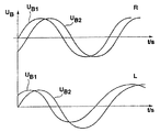
図5及び図6は、例えば車輪の回転方向検出のための評価を示している。このために図5には図3に対して修正を加えたホール効果センサ或いは磁気抵抗式センサであるセンサエレメント1021bが備えられている。修正は、図3に見られる様な既知のホイートストンブリッジに更に2つの抵抗が補足されているということにある。修正されたホイートストンブリッジではなくて修正されたホール効果センサ或いは磁気抵抗式センサは、少なくとも2つの別々の感応エレメント10211及び10212(図6参照)或いは2つの完全なホイートストンブリッジによって示すことも出来る。ここでもまた、歯車リム、回転子、或いはパルス発生輪(図2の参照符号101)の個別エレメントは、ブリッジ電圧信号UB1及びUB2に対応する変化を生み出す。これ等のブリッジ電圧信号は,評価ユニット5201へ送られる。同時に有効信号の評価のために少なくとも一つのブリッジ電圧信号が既に説明された比較器5031に送られる。回転方向検出の評価ユニット5201の機能を、図7及び図8に基づいて説明する。
【0041】
図7及び図8には、図5に示されているブリッジ電圧信号の変化が示されている。このために、時間tの経過に伴う変化、或いはパルス発生輪の変位s或いは回転角に対する変化を観察することが出来る。車輪の回転方向に応じて先ず修正されたホイートストンブリッジの右側の部分が先ず変調されるか或いは左側の部分が変調される。車輪が右回転する場合は、ブリッジ電圧UB1がブリッジ電圧UB2に先行するのに対して、車輪が左回転する場合にはその反対となる。回転方向の評価ユニット5201によって、両方のブリッジ電圧の動きの位相変位が評価され、車輪が後方へ動くと信号DRが生成される。これとは別の方法として、図8に見られる様に、二つのブリッジ電圧値UB1とUB2の間の差ΔUBを取ることも出来る。この差ΔUBの変化から、特に最大値と最小値の位置(“上”或いは“下”の後のピーク)から回転方向(前進/後退)に関する情報DRが得られる。
【0042】
このようにして、図5に示されている総合センサ回路1024bは、回転数信号N或いはDFの他に、値1/0を取るデジタルの回転方向信号DRを送り出す。
【0043】
図9は、本発明に基づくシステムの一つの実施態様を示している。この図では参照符号502によって追加信号を持つセンサユニットが示され、また参照符号503によって評価ユニットが示されている。
【0044】
センサユニット502には、総合センサ回路1024a/bが含まれている。総合センサ回路1024a/bは、既に説明された総合センサ回路1024a及び1024bが組み合わせられたものとして、回転数信号N或いはDFと追加信号LS、EL、及びDRの両方を送り出す。センサユニット502には更に、図2に基づいて説明された、ブレーキライニングの摩耗BBVを検出するためのスイッチ1041が含まれている。
【0045】
回転数信号DFと追加信号LS、EL、DR、及びBBV(ブレーキライニング摩耗信号)は、スイッチ制御ユニット1025へ送られる。このユニット1025によって電流源1023の電流i1がスイッチング信号Sc及びスイッチSを用いてオンオフされる。
【0046】
スイッチ制御ユニット1025の機能を先ず第1の実施態様の場合について図10を参照して説明する。
図10の信号列601は、本来の回転数信号DFが示されている。ここで説明される実施例ではロー(電流値i1)からハイ(電流値i2)への、並びにその逆のハイからローへの、DF信号(信号列601)の全ての交替(信号パルス側面)は、トリガ信号として、前もって定めることの出来る持続時間の電流パルスを起動させるために利用される。この電流パルスの持続時間は、追加信号EL、LS、DR、及びBBVの値に依存している。
【0047】
通常運転時にはパルス発生輪101(図2)は右方向或いは左方向に回転する。このことは信号DRによって表示される。例えばパルス発生輪102が左回転をしていると、信号DFのパルス側面によって持続時間100μ秒の電流パルスが起動或いはトリガされる。これに対応してスイッチング信号Scがスイッチ制御ユニット1025によって形成されるので、結果として、信号列603aに示されている信号IDSxyの変化がセンサユニット502の出力端に形成される。パルス発生輪が右回転をしていると、持続時間200μ秒のパルスが生成される。この場合には信号列604aに示されている信号が生成される。
【0048】
信号列605a及び606aは、左回転の間(605a、パルス持続時間:400μ秒)或いは右回転の間(606a、パルス持続時間:800μ秒)に誤った取り付け状態(信号EL)がある場合の信号IDSxyの時間的変化を示している。
【0049】
信号列605a及び606aは、センサエレメントの取り付けの後で、例えば車両の製造の際に或いは工場で、正しい取り付け状態をチェックしなければならない時に、特に重要である。
【0050】
過度のブレーキライニング摩耗を知らせるためには、例えば600μ秒のパルス持続時間を起動することが出来る。これは図10では見ることは出来ない。
対応する値LSの存在によって、過度の空隙があることが示されると、50μ秒の(比較的短い)パルス持続時間がトリガーされる。これは信号列602aで見ることが出来る。例えば、ブレーキシステムで車輪回転数を検出する際には過度の空隙の存在は安全性に係わるので、信号LSがある場合には他の全ての追加信号DR、EL、及びBBVはフェードアウトされる。これは、本来の回転数情報の他には、“過剰空隙”情報だけが50μ秒のパルスの起動によって伝送される、ということを意味している。即ち、空隙の限界域では回転方向信号も取り付け信号もブレーキライニング摩耗信号も伝達されない。
【0051】
本来の回転数情報はいずれの場合にも信号IDSxyのローからハイへのパルス側面の間の時間間隔に入っている。
図11に示されている信号の変化は、図10に示されている信号の変化と類似の条件を背景としている。主な相違点は、パルスの起動或いはトリガーの前に信号DF(信号列601)の側面によって先ず一定の持続時間Δtの間信号IDSxyが値i1或いはローにセットされるということにある。同じことは、伝送されるべき追加情報によって、レベルi2が調整される時にも行われる。例えば50μ秒のその様なロー・ビットを前置することによって、回転数情報がいつでも、従って追加情報によって“長い”ハイ・レベルの場合でも、確実に伝達されるということが保証される。
【0052】
信号列602bから606bまでは、前置されているロー・ビットに至るまで、図10の信号列と同じである。
これまではパルス発生輪101が回転している運転状態について説明したが、図12では静止状態にある信号IDSxyの信号の変化について説明する。
【0053】
前もって定めることの出来る時間の間、例えば1秒の間、回転数信号DFの側面交替が生じない場合(信号列701a)には、それでもセンサユニット502から信号列702aに示されているように、信号IDSxyが送り出される。このような2つの静止時パルスの間の時間的間隔は、図示の例では1秒である。パルス持続時間は、ここではLS=パルス持続時間(50μs)の32倍、従って、1.6m秒、である。このパルス幅は、回転数信号DFが検知されない限り、低圧の後も送り出される。
【0054】
図13には比較的高い回転速度の場合或いは上昇中の回転速度の場合の状況が示されている。このことは信号列701bの信号DFの周波数の上昇から知られる。
【0055】
回転数が上昇して行く際には、追加情報(LS、EL、DR、BBV)を含んでいるパルス幅(この例の場合には、200μ秒)が状況によっては回転数信号DFのハーフ周期長さよりも長くなってしまうという問題が生じる。図13に示されている時点Aの前では、パルス幅はハーフ周期長さよりも短い。これによって時点Aの前では追加情報は対応するパルス幅で確実に伝達されることが出来る。しかしながらこの時点Aの後では、信号DFのハーフ周期長さはパルス幅のためには短か過ぎる。
【0056】
定められた回転速度まで、例えば車両の場合には、約50km/h、またデューティー比TVgrenz 例えば0.3まで、は信号−パルス幅は正しく、従って長さがそのまま、送り出される。この速度を越えると(図13の時点A)縮小されたパルス幅しか出力されない。このことは後に説明される評価ユニット503の中で考慮される。評価503ユニットはこの限界を検知し、この限界の情報では、パルス幅が確実に伝達される信号だけしか評価しない。
【0057】
図9において、信号IDSxyは、対応するコンタクトによって評価ユニット503へ送られる。評価回路5035で重要なのはパルス幅変調(PWM)評価論理ブロック5037と時間間隔ブロック5038である。
【0058】
パルス幅変調(PWM)評価論理ブロック5037では、前置増幅器の後で、信号IDSxyのパルス幅(例えば、図10、図11、図12、及び図13参照)が評価される。既に説明されたように、各々のパルス幅には一つの追加信号が割り当てられており、この割り当てが評価ユニット503に記憶されている。これによってマイクロコンピュータ5036に追加情報(LS、EL、DR、BBV)を送り込むことが出来る。
【0059】
時間間隔ブロック5038では、前置増幅器の後で、ローからハイへの2つのパルス側面の間の時間的間隔が求められる。既に説明されたように、この時間間隔は回転数周波数に対応しており、その後の評価のためにマイクロコンピュータ5036に送られる。
【0060】
時間間隔ブロック5038では、2つの信号列によって、信号IDSxyを示している上側の信号列の各々のロー・ハイの信号側面が下側の信号列の中で電流レベル或いは電圧レベル同士の間の交替を生じさせているということが略示されている。このようにして、時間間隔ブロック5038で(元の)回転数DFが復元される。
【0061】
既に説明されたように、パルス幅変調(PWM)評価論理ブロック5037には限界値が記憶されており、その限界値までは、追加情報を含んでいるパルス幅が確実に伝達されることが出来る。この限界値を越えるとマイクロコンピュータ5036には最早追加情報は送り込まれない。
【0062】
まとめ
実施例が示しているように、センサユニット502と評価ユニット503との間の本発明に基づくデータ伝送のためには、2つの電流レベル或いは電圧レベルしか必要とされない。
【0063】
追加情報の評価は比較的簡単である。何故なら評価ユニット503で測定されなければならないのはパルス幅だけだからである。出来るだけ長いパルスによってデータの確実性を改善することが出来る。何故なら出来るだけ長いパルスによって最大の障害抑圧(ろ波)が可能だからである。
【0064】
本発明によれば、少なくとも原理的には、追加情報を伝達するために唯一つのパルスだけで十分である。更に本発明は、わずかな側面交替しか必要ではなく、その結果信号、IDSxyの妨害放射も少なくなる。
【0065】
低い回転速度の時にだけ必要である追加情報(例えば、取り付け状態EL)は長いパルスを割り当てられているのに対して、最大回転速度の下で必要となる追加情報(例えば、空隙LS)は短いパルスによって表されている。
【0066】
ローの持続時間Δtの前置によって、高い周波数(高い回転速度)の下でも回転速度のより確実な伝達を保証することが出来る。
ほぼ毎秒毎の静止信号伝達とそれに付随する代表的パルス幅によって、センサ及び導線の監視が可能である。
【0067】
取り付け状態(EL)の伝達によって、製造の際にベルトエンドで或いは工場で、回転数センサの取り付け状態をチェックすることが出来る。
【図面の簡単な説明】
【図1】技術の技術によって知られている、自動車のブレーキライニングの摩耗と車輪回転数を求めるためのシステムの概略ブロック図を示す。
【図2】アクティブ回転数センサとブレーキライニング摩耗センサとの簡単な組み合わせを示す。
【図3】回転速度が検出されるべき車両の車輪における歯車のリムに対するホール効果センサ或いは磁気抵抗式のセンサの検出装置を示す。
【図4】図3における時間の経過に伴うブリッジ電圧UBの信号の変化を示す。
【図5】図3に対して修正を加えたホール効果センサ或いは磁気抵抗式センサのセンサの検出装置を示す。
【図6】図5におけるセンサエレメントとパルス発生輪との配置関係を示す。
【図7】図5における回転方向検出の評価ユニットの機能を説明するためにブリッジ電圧信号の変化を示す。
【図8】図5における回転方向検出の評価ユニットの機能を説明するために別のブリッジ電圧信号の変化を示す。
【図9】本発明に基づくシステムの実施態様のブロック図を示す。
【図10】図9のシステムにおける各種信号の変化を示す
【図11】図9のシステムにおける各種信号の別の変化を示す
【図12】図9のシステムにおける各種信号の更に別の変化を示す
【図13】図9のシステムにおける各種信号の更に別の変化を示す
【符号の説明】
図1において
11a〜11d・・・自動車の車輪ユニット、 14a〜14d・・・ブレーキシステム、 16a〜16d・・・伝送線、 18a〜18d・・・導線、 102a〜102d・・・回転数センサとブレーキライニング摩耗センサ、 103・・・制御装置、105a〜105d・・・伝送線、 110・・・表示器
図2において
101・・・増分ロータ(パルス発生輪)、 102・・・回転数センサ、 103・・・制御装置、 104・・・ブレーキライニング摩耗センサ、 105、106・・・信号線、 1021・・・センサエレメント、 1022、1023・・・電流源、 1021a〜1021d、1031a〜1031d・・・差込み接続器、 1036・・・入力増幅器、 1037・・・評価回路、 1041・・・スイッチ(コンタクトピンを表している)、 R・・・入力抵抗、 U+・・・電圧、
図3において
1021a・・・センサエレメント、 1024a・・・総合センサ回路、 5031・・・K1(第1の比較器)、5101・・・K2(第2の比較器)、5102・・・検出ユニット
図5において
1021b・・・センサエレメント、 1024b・・・総合センサ回路、 5031・・・比較器、 5201・・・評価ユニット
図6において
101・・・パルス発生輪、 10211、10212・・・感応エレメント
図9において
502・・・センサユニット、 503・・・評価ユニット、 1022、1023・・・電流源、 1024a/b・・・総合センサ回路、 1025・・・スイッチ制御ユニット、 1041・・・スイッチ(コンタクトピン)、 5035・・・評価回路、5036・・・マイクロコンピュータ、 5037・・・パルス幅変調(PWM)評価論理ブロック、 5038・・・時間間隔(回転数復元)ブロック、 S・・・スイッチ、 Sc・・・スイッチ信号、[0001]
BACKGROUND OF THE INVENTION
The present invention relates to a signal generation system for superimposing information.
[0002]
[Prior art]
More and more sensors are being used to control or regulate automobile events. However, this means that more and more sensor signals must be transmitted to the control or regulation unit independently of each other. In doing so, each individual signal must meet different requirements. If individual signals are combined into a single “sum signal”, individual requirements must be maintained.
[0003]
It is known to measure the rotational speed of a vehicle wheel in order to adjust or control the braking force, driving force and / or kinematics of a motor vehicle. In the prior art, various methods (for example, use of a Hall sensor or a magnetoresistive sensor) are implemented for this purpose. Furthermore, it is known to detect the wear of the brake lining in the brakes of the vehicle, in which case, for example, contact pins are embedded at a certain depth of the brake lining, and when the brake lining wears to that depth, the contact is work.
[0004]
For example, the article “Integrated Hall Effect Sensors for Position and Rotation Detection” published in pages 29-31 of the July 1995 issue of “elektronik industry” (Electronic Industry) magazine includes an anti-blocking system, Active sensors used in automobiles for drive slip systems, engine and gear control or regulation systems are shown. These sensors supply two current levels in a two-wire circuit, and these current levels are converted into two voltage levels by a measuring resistor in the corresponding control device.
[0005]
In addition to the Hall effect sensors mentioned above, the use of magnetoresistive sensors for rotational speed detection is also described in the article “Magnetoresistive Based,” published for example in VDI Report 1984, No. 509. It is known from “a new and alternative solution for motor speed sensors”. DE-C2-26,06,012 (US Pat. No. 4,076,330) describes a special common device for detecting brake lining wear and detecting wheel speed. For this purpose, the detected brake lining wear and the wheel speed detected by the inductive sensor are sent to the evaluation unit via a common signal line. This is achieved in that the wheel speed sensor is all or partially shorted in response to the detected brake lining wear.
[0006]
Other systems, for example as known from DE-C-43, 22, 440, are used between wheel units and evaluation units for the detection of speed and brake lining wear of wheels or wheel brakes. Requires at least two signal lines.
[0007]
In the case of rotational speed detection as described above, it is known that the gap between the rotating gear rim and the original sensor element has a significant effect on the quality of the rotational speed signal. . In this regard, refer to, for example, DE-OS 32, 01, 811.
[0008]
Further, for example, in the case of start support (so-called “hill holder”), information on the rotation direction of the wheel is necessary. In this case, in particular, information about whether the car is moving backwards is needed. In this regard, see, for example, DE-OS 35,10,651.
[0009]
The aforementioned information, as well as other or additional information (eg, brake lining wear, air gap, direction of rotation) is generally detected near the wheel and evaluated by a control unit located away from the wheel. For this purpose, the information must be transmitted to the control unit.
[0010]
In the case of a prime mover (internal combustion engine and / or electric motor), it is known that the rotational speed of the prime mover is detected by an inductive sensor, a magnetoresistive sensor, or a Hall effect sensor.
[0011]
In German Patent Application No. 19609062.8, an analog speed signal, which periodically takes two pre-applied current or voltage levels, along with digital information regarding brake lining wear, air gap and / or direction of rotation, It has been proposed to superimpose so that the current or voltage level of the analog speed signal is changed in a coded manner. Increasing the current level for transmitting additional digital information has the advantage that it only requires a set of two-wire connections between the sensor unit and the control unit. However, by raising the current level, in addition to the increase in power loss, the voltage drop due to the measurement resistance in the control unit also increases. A change in voltage level does not increase power loss, but requires a three-wire connection (voltage supply, ground, signal line) between the sensor unit and the control unit.
[0012]
[Problems to be solved by the invention]
An object of the present invention is to realize as simple and reliable superimposition of rotation speed information and additional information as possible.
[0013]
[Means for Solving the Problems]
The signal generation system for superimposing information according to the present invention includes a signal (I) including first information indicating the rotation speed of the rotating portion and including at least second information (LS, DR, BBV, EL). DSxy ), A signal (I) that alternates in time between the first and second current and / or voltage levels (high / low). DSxy ) Is generated. The first information is the same kind of alternation between the first level and the second level (high / low = side or amplitude) or from the second level to the first level (low / low). High = side or amplitude). The second information is indicated by the time length of the first level or the second level.
[0014]
The present invention is derived from a system for generating a signal, wherein the signal includes at least second information in addition to first information indicating the rotational speed of the rotating part. The signal alternates in time between first and second current and / or voltage levels (high / low).
[0015]
A feature of the present invention is that the first information is the same type of change from the first level to the second level (high / low = side) or from the second level to the first level. It is to be indicated by the time interval between alternations (low / high = side). On the other hand, the second information is indicated by the time length of the first level or the second level.
[0016]
The present invention has the advantage that no other current or voltage level is required for the transmission of additional information compared to the prior art described at the outset. Furthermore, the evaluation of the additional information can be realized relatively easily because only the first or second level of time length and thus the pulse width need be measured for the evaluation of the additional information. It is. The invention further offers the possibility of achieving high data security with as long a pulse as possible.
[0017]
In one particularly advantageous embodiment, the system according to the invention is used in a motor vehicle. The first information is the number of revolutions of the wheels of the motor vehicle, the number of revolutions of the prime mover of the car made as a gasoline, diesel and / or electric motor, and / or the number of revolutions of the shaft operatively coupled with the gears of the car Is shown. The second information includes at least one information component, and the information component is
The spacing between the rotating part and the sensor element for detecting the rotational speed, and / or
Wear of brake linings of at least one wheel brake, and / or
Direction of rotation (DR) of the rotating part, and / or
Sensor element installation position (EL) for detecting rotational speed,
Is shown.
[0018]
Particularly advantageously, the information components conveyed by the signal are assigned different priorities, such that when there is an information component with the highest priority, no other information component is transmitted. This guarantees that the most important information is reliably transmitted.
[0019]
According to the present invention, the rotational speed information is transmitted according to the time interval between the same type of alternation (high / low = flank or low / high = side). In one particularly advantageous embodiment of the invention, said signal is provided at least in advance prior to this kind of alternation (high / low = side or low / high = side) which is important for rotational speed information. During the possible time interval, the current and / or voltage level (high / low) that the signal had before the turn is generated to be adjusted. The adjustment of the level according to the invention (“previous bit”) prior to the original turn to be evaluated for the rotational speed information ensures a reliable transmission of the rotational speed signal in all cases.
[0020]
The adjustment of the level (“previous bit”) before the actual alternation is such that a trigger signal is generated and, in response to the generation of this trigger signal, the signal is the first or second current and / or voltage. This can be done by being placed on the level (high / low). In particular, the trigger signal is generated depending on the rotational speed of the rotating part.
[0021]
In another alternative embodiment of the invention, said signal may be said first or second during a defined time interval that can be given in advance when said rotating part stops. It is generated to have two current and / or voltage levels (high / low). This makes it possible to sense the stationary part of the rotating part. As a result, it is possible to check that there is no abnormality in the functions of the sensor element and the transmission line.
[0022]
In another embodiment of the invention, an advantageous method for evaluating a signal generated according to the invention is described. For this evaluation, firstly, from the signal generated according to the present invention, the rotation value indicating the rotation speed of the rotating part is the same type of change from the first level to the second level (high / low = side). ) Or the time interval between similar turns (low / high = side) from the second level to the first level. The rotation value is compared with at least one threshold value. An evaluation of the time length of the first or second level is performed depending on the result of the comparison to determine the second information. Therefore, the rotational speed of the rotating part is advantageously taken into account when evaluating the second information. At that time, if a larger rotation number exists, only the second information portion can be evaluated. This ensures that only second information that can be reliably transmitted is evaluated.
[0023]
In particular, it is considered that the information component having the highest priority is evaluated up to a larger rotational value than the information component having a lower priority.
[0024]
【Example】
FIG. 1 shows, as a schematic block diagram, a system for determining the wear and wheel speed of a brake lining of an automobile.
[0025]
In FIG. 1,
[0026]
Output signals of the rotational speed sensor and the brake
[0027]
The brake systems of the
[0028]
FIG. 2 shows a simple combination of the detection functions of an active speed sensor and a brake lining wear sensor. As already described at the beginning, the “active”
[0029]
The
[0030]
[Expression 1]
In essence, a typical course under a constant wheel speed is shown in
[0032]
In the lower part of FIG. 2, a brake
[0033]
As can be seen in the embodiment shown in FIG. 2, separate conductors (signal lines) 105 and 106 are required for the transmission of wheel speed information and information about the state of the brake lining, respectively.
[0034]
FIG. 3 shows by way of example a detection device for excessive spacing of Hall effect sensors or magnetoresistive sensors on the already described gear rims of the wheels of the vehicle whose rotational speed is to be detected. The
[0035]
FIG. 4 shows the bridge voltage U over time. B The change of a typical signal is shown. Depending on the passing speed of the individual segments of the gear rim, the bridge voltage U B Rises periodically or falls periodically. If the distance between the gear rim and the
[0036]
The first threshold comparison in
[0037]
The absence of the signal K2 is detected by the
Summarizing the detection of the air gap, it can be said that the rotational speed of the wheel is detected by an active sensor, for example, a Hall effect sensor or a magnetoresistive sensor. These sensors include a Wheatstone bridge that is modulated by changes in the magnetic field. A signal relating to the rotational speed is obtained from this modulation. The amount of modulation is a constant ratio with respect to the magnitude of the magnetic field strength difference between the two bridge halves. The difference in magnetic field strength depends in particular on the distance of the sensor relative to the rotor. If the amount of bridge modulation is evaluated, the air gap between the sensor and the rotor can be estimated. This evaluation is based on the hysteresis of the normal effective signal comparator 5031 (U H = 20 mV) greater hysteresis (U H = 60 mV). If the gap is small, both comparators are switched, but if the gap is too large, only the
[0038]
By introducing a third threshold, for example 30 mV, not shown in FIG. 4, it is possible to detect an incorrect mounting state of the
[0039]
As described above, the
[0040]
5 and 6 show an evaluation for detecting the rotational direction of a wheel, for example. For this purpose, FIG. 5 is provided with a
[0041]
7 and 8 show changes in the bridge voltage signal shown in FIG. For this reason, it is possible to observe a change with the passage of time t, or a change with respect to the displacement s or the rotation angle of the pulse generation wheel. Depending on the direction of rotation of the wheel, the right part of the modified Wheatstone bridge is first modulated or the left part is modulated. If the wheel rotates clockwise, the bridge voltage U B1 Is the bridge voltage U B2 The opposite is true when the wheel rotates counterclockwise. The rotational
[0042]
In this way, the
[0043]
FIG. 9 shows one embodiment of a system according to the present invention. In this figure,
[0044]
The
[0045]
The rotation speed signal DF and the additional signals LS, EL, DR, and BBV (brake lining wear signal) are sent to the
[0046]
The function of the
The
[0047]
During normal operation, the pulse generating wheel 101 (FIG. 2) rotates rightward or leftward. This is indicated by the signal DR. For example, when the
[0048]
The signal trains 605a and 606a are signals when there is an erroneous mounting state (signal EL) during the left rotation (605a, pulse duration: 400 μsec) or during the right rotation (606a, pulse duration: 800 μsec). I DSxy This shows the change over time.
[0049]
The signal trains 605a and 606a are particularly important after the installation of the sensor element, for example when manufacturing the vehicle or at the factory, when the correct installation status has to be checked.
[0050]
To signal excessive brake lining wear, a pulse duration of 600 μs, for example, can be activated. This cannot be seen in FIG.
If the presence of the corresponding value LS indicates that there is excessive air gap, a 50 μs (relatively short) pulse duration is triggered. This can be seen in
[0051]
The original rotational speed information is in each case the signal I DSxy The time interval between the pulse sides from low to high is entered.
The change in the signal shown in FIG. 11 is based on a similar condition to the change in the signal shown in FIG. The main difference is that the signal DF (signal sequence) before the triggering or triggering of the pulse 601 ) First, the signal I for a certain duration Δt. DSxy Is the value i 1 Or it is set to low. The same is true for level i depending on the additional information to be transmitted. 2 It is also done when is adjusted. Prefixing such a low bit of e.g. 50 μs ensures that the rotation speed information is transmitted reliably at any time and therefore even in the case of a “long” high level with additional information.
[0052]
The signal trains 602b to 606b are the same as the signal train of FIG. 10 up to the preceding low bit.
The operation state in which the
[0053]
If the side change of the rotational speed signal DF does not occur during a pre-determinable time, for example for 1 second (
[0054]
FIG. 13 shows the situation when the rotational speed is relatively high or when the rotational speed is increasing. This is known from the increase in the frequency of the signal DF in the signal sequence 701b.
[0055]
When the rotational speed increases, the pulse width (200 μs in this example) including additional information (LS, EL, DR, BBV) may be a half cycle of the rotational speed signal DF depending on the situation. The problem that it becomes longer than length arises. Before the time point A shown in FIG. 13, the pulse width is shorter than the half cycle length. This ensures that additional information can be reliably transmitted with the corresponding pulse width before time A. However, after this point A, the half period length of the signal DF is too short for the pulse width.
[0056]
Up to a defined rotational speed, for example in the case of a vehicle, about 50 km / h and a duty ratio TVgrenz, for example up to 0.3, the signal-pulse width is correct and therefore the length is sent as it is. When this speed is exceeded (time A in FIG. 13), only a reduced pulse width is output. This is considered in the evaluation unit 503 described later. The evaluation 503 unit detects this limit, and with this limit information, it evaluates only those signals whose pulse width is reliably transmitted.
[0057]
In FIG. 9, the signal IDSxy is sent to the evaluation unit 503 by the corresponding contact. Important in the evaluation circuit 5035 are a pulse width modulation (PWM)
[0058]
In a pulse width modulation (PWM)
[0059]
In the time interval block 5038, after the preamplifier, the time interval between the two pulse sides from low to high is determined. As already explained, this time interval corresponds to the rotational frequency and is sent to the
[0060]
In the time interval block 5038, the signal I is represented by two signal sequences. DSxy It is schematically shown that the low and high signal sides of each of the upper signal trains showing the cause of the alternation between current levels or voltage levels in the lower signal train. In this way, the (original) rotational speed DF is restored in the time interval block 5038.
[0061]
As already described, a limit value is stored in the pulse width modulation (PWM)
[0062]
Summary
As the example shows, only two current or voltage levels are required for data transmission according to the invention between the
[0063]
Evaluation of additional information is relatively simple. This is because only the pulse width has to be measured by the evaluation unit 503. Data reliability can be improved with as long a pulse as possible. This is because maximum disturbance suppression (filtering) is possible with a pulse that is as long as possible.
[0064]
According to the invention, at least in principle, only one pulse is sufficient to convey additional information. Furthermore, the present invention requires only a slight side change, so that the signal I DSxy The amount of interference radiation is also reduced.
[0065]
Additional information that is needed only at low rotational speeds (eg, mounting state EL) is assigned a long pulse, whereas additional information that is needed under maximum rotational speed (eg, gap LS) is short. It is represented by a pulse.
[0066]
The preposition of the low duration Δt ensures a more reliable transmission of the rotational speed even at high frequencies (high rotational speed).
Sensors and conductors can be monitored with a stationary signal transmission approximately every second and a typical pulse width associated therewith.
[0067]
By transmitting the mounting state (EL), it is possible to check the mounting state of the rotation speed sensor at the belt end or at the factory during manufacture.
[Brief description of the drawings]
FIG. 1 shows a schematic block diagram of a system for determining the wear and wheel speed of an automobile brake lining known from the state of the art.
FIG. 2 shows a simple combination of an active speed sensor and a brake lining wear sensor.
FIG. 3 shows a detection device for a Hall effect sensor or a magnetoresistive sensor for a gear rim on a vehicle wheel whose rotational speed is to be detected.
4 shows a bridge voltage U over time in FIG. B Changes in the signal are shown.
FIG. 5 shows a sensor detection device of a Hall effect sensor or a magnetoresistive sensor with a modification to FIG.
6 shows an arrangement relationship between sensor elements and pulse generation wheels in FIG. 5;
7 shows changes in the bridge voltage signal for explaining the function of the evaluation unit for detecting the rotational direction in FIG. 5. FIG.
FIG. 8 shows another bridge voltage signal change to explain the function of the rotation direction detection evaluation unit in FIG. 5;
FIG. 9 shows a block diagram of an embodiment of a system according to the present invention.
10 shows changes in various signals in the system of FIG.
11 shows another change of various signals in the system of FIG.
12 shows yet another variation of various signals in the system of FIG.
13 shows yet another variation of various signals in the system of FIG.
[Explanation of symbols]
In FIG.
11a to 11d: automobile wheel unit, 14a to 14d ... brake system, 16a to 16d ... transmission line, 18a to 18d ... conductive wire, 102a to 102d ... rotation speed sensor and brake
In FIG.
DESCRIPTION OF
In FIG.
1021a ... sensor element, 1024a ... total sensor circuit, 5031 ... K1 (first comparator), 5101 ... K2 (second comparator), 5102 ... detection unit
In FIG.
1021b ... sensor element, 1024b ... total sensor circuit, 5031 ... comparator, 5201 ... evaluation unit
In FIG.
101 ... pulse generating wheel, 10211, 10212 ... sensitive element
In FIG.
502 ... sensor unit, 503 ... evaluation unit, 1022, 1023 ... current source, 1024a / b ... total sensor circuit, 1025 ... switch control unit, 1041 ... switch (contact pin) 5035 ... Evaluation circuit, 5036 ... Microcomputer, 5037 ... Pulse width modulation (PWM) evaluation logic block, 5038 ... Time interval (revolution recovery) block, S ... Switch, Sc. ..Switch signals,
Claims (8)
前記スイッチ制御ユニット(1025)は、時間的に第1と第2の電流レベル及び電圧レベル(ハイ/ロー)の少なくともいずれかのレベルの間で交替する前記信号を生成し、
前記第1の情報が、第1のレベルから第2のレベルへの同種の交替(ハイ/ロー側面)の間の時間的間隔、或いは第2のレベルから第1のレベルへの同種の交替(ロー/ハイ側面)の間の時間的間隔によって示され、
前記第2の情報が、前記第1のレベル或いは前記第2のレベルの時間的長さによって示される、前記信号生成システムにおいて、
前記スイッチ制御ユニット(1025)が、前記交替に先立って、前記信号を、前もって定めることが出来る持続時間にわたって前記電流レベル及び電圧レベルの少なくともいずれかのレベルに設定するように構成されることを特徴とする信号生成システム。A signal comprising a switch control unit (1025) for generating a signal including first information (DF) indicating the rotation speed of the rotating part and at least two pieces of second information (LS, DR, BBV, EL) (I DSxy ) generation system,
It said switch control unit (1025) generates the signal alternates between at least one of the level of temporally first and second current and voltage levels (high / low),
Said first information from the first level time intervals between the same kind of alternation to the second level (high / low side), or from the second level of the same species to the first level Indicated by the time interval between turns (low / high side) ,
In the signal generation system, wherein the second information is indicated by a time length of the first level or the second level ,
Said switch control unit (1025) is, prior to the front Ki交 exchange, the signal is configured to set for the duration that can be defined in advance in at least one of levels of the current and voltage levels A signal generation system characterized by this .
前記第1の情報が、
自動車の車輪の回転数、
ガソリンエンジン、ディーゼルエンジン、電動モータの少なくともいずれかの形態の自動車の原動機の回転数、
自動車のギヤと作用結合された軸の回転数
の少なくともいずれかを示し、
前記第2の情報(LS,DR,BBV,EL)が、
前記回転部分と、前記回転速度を検出するセンサエレメントとの間の距離(LS)、
少なくとも一つの車輪ブレーキのブレーキライニングの摩耗(BBV)、
前記回転部分の回転方向(DR)
前記回転速度を検出するセンサエレメントの組み込み位置(EL)
の少なくとも一つの情報成分を含むことを特徴とする請求項1ないし3のいずれかに記載の信号生成システム。The signal generation system is used in an automobile;
The first information is
Car wheel speed,
The number of revolutions of the motor of the automobile in the form of at least one of a gasoline engine, a diesel engine, and an electric motor,
Indicates at least one of the rotational speeds of the shaft operatively coupled to the gear of the automobile,
The second information (LS, DR, BBV, EL)
A distance (LS) between the rotating part and a sensor element for detecting the rotational speed;
Wear of the brake lining (BBV) of at least one wheel brake,
Direction of rotation of the rotating part (DR)
Sensor element installation position (EL) for detecting the rotational speed
4. The signal generation system according to claim 1, comprising at least one information component.
前記評価回路は、
前記回転部分の前記回転速度を示す回転数変数を、前記第1のレベルから第2のレベルへの同種の交替(ハイ/ロー側面)の間の時間的間隔、或いは第2のレベルから第1のレベルへの同種の交替(ロー/ハイ側面)の間の時間的間隔から決定し、
前記回転数変数を、少なくとも一つの限界値と比較し、
前記比較の結果に基づいて、前記第2の情報を決定するために、前記第1のレベルまたは前記第2のレベルの時間的長さを評価するように構成されることを特徴とする請求項1または2に記載の信号生成システム。An evaluation circuit (5035) for evaluating the generated signal;
The evaluation circuit includes:
The rotational speed variable indicating the rotational speed of the rotating portion is changed from the first level to the second level by a time interval between the same type of change (high / low side surface), or from the second level to the first level. Determined from the time interval between similar turns to the level of (low / high side),
Comparing the rotational speed variable with at least one limit value;
The method according to claim 1, wherein the second information is configured to evaluate a time length of the first level or the second level to determine the second information based on the result of the comparison. 3. The signal generation system according to 1 or 2.
Applications Claiming Priority (2)
| Application Number | Priority Date | Filing Date | Title |
|---|---|---|---|
| DE19937155.5 | 1999-08-06 | ||
| DE19937155A DE19937155A1 (en) | 1999-08-06 | 1999-08-06 | System for generating a signal for superimposing information |
Publications (3)
| Publication Number | Publication Date |
|---|---|
| JP2001088632A JP2001088632A (en) | 2001-04-03 |
| JP2001088632A5 JP2001088632A5 (en) | 2007-04-12 |
| JP4504527B2 true JP4504527B2 (en) | 2010-07-14 |
Family
ID=7917447
Family Applications (1)
| Application Number | Title | Priority Date | Filing Date |
|---|---|---|---|
| JP2000234106A Expired - Fee Related JP4504527B2 (en) | 1999-08-06 | 2000-08-02 | Signal generation system for information superposition |
Country Status (4)
| Country | Link |
|---|---|
| US (1) | US6653968B1 (en) |
| EP (1) | EP1074843B1 (en) |
| JP (1) | JP4504527B2 (en) |
| DE (2) | DE19937155A1 (en) |
Families Citing this family (68)
| Publication number | Priority date | Publication date | Assignee | Title |
|---|---|---|---|---|
| JP4964358B2 (en) * | 1999-12-07 | 2012-06-27 | 株式会社デンソー | Rotation sensor detection signal processing apparatus and rotation sensor detection signal output method |
| DE50109566D1 (en) * | 2000-11-22 | 2006-05-24 | Continental Teves Ag & Co Ohg | ACTIVE MAGNETIC SENSOR FOR ELECTRONIC BRAKING SYSTEMS |
| DE10146949A1 (en) * | 2000-11-22 | 2002-06-06 | Continental Teves Ag & Co Ohg | Active magnetic sensor for electronic brake systems |
| DE10115715B4 (en) * | 2001-03-30 | 2004-10-14 | Plöchinger, Heinz, Dipl.-Ing. | Sensor and method for recording measured variables and physical parameters |
| WO2002090999A1 (en) * | 2001-05-10 | 2002-11-14 | Continental Teves Ag & Co. Ohg | Wheel speed sensor arrangement with transmission of additional information |
| DE10130130B4 (en) * | 2001-06-22 | 2007-09-20 | Minebea Co., Ltd. | Device for generating a speed-dependent signal for an electric motor, in particular for an electronically commutated DC motor |
| FR2842913B1 (en) * | 2002-07-23 | 2004-11-19 | Schlumberger Services Petrol | COMPACT DEVICE FOR MEASURING SPEED AND DIRECTION OF ROTATION OF AN OBJECT |
| DE10345728B4 (en) * | 2003-10-01 | 2012-05-31 | Robert Bosch Gmbh | Method and arrangement for evaluating the signals of a sensor arrangement |
| JP2005134283A (en) | 2003-10-31 | 2005-05-26 | Aisin Seiki Co Ltd | Current output sensor of two-wire system, and ic for the same |
| JP4196345B2 (en) * | 2004-02-18 | 2008-12-17 | 株式会社デンソー | Valve open / close control device |
| DE102004009715A1 (en) * | 2004-02-27 | 2005-09-22 | Küster Automotive Control Systems GmbH | Automotive rotation speed measurement device, comprises an integrated circuit the output of which is a pulse sequence in which pulse separation represents the speed and pulse width the direction of rotation |
| JP4605435B2 (en) * | 2004-03-24 | 2011-01-05 | アイシン精機株式会社 | Rotation detector |
| US7365530B2 (en) * | 2004-04-08 | 2008-04-29 | Allegro Microsystems, Inc. | Method and apparatus for vibration detection |
| DE102004034865A1 (en) * | 2004-07-19 | 2006-02-16 | Siemens Ag | Sensor for measuring the position of an actuator |
| FR2878334B1 (en) * | 2004-11-22 | 2007-03-16 | Skf Ab | DEVICE FOR DETECTING AND DISPLAYING ROTATION PARAMETERS OF A WHEEL, VEHICLE, AND VEHICLE THEREFOR |
| JP4441871B2 (en) * | 2005-01-19 | 2010-03-31 | 株式会社デンソー | Distributed control system and control device thereof |
| US7253614B2 (en) * | 2005-03-21 | 2007-08-07 | Allegro Microsystems, Inc. | Proximity detector having a sequential flow state machine |
| DE102005016267A1 (en) * | 2005-04-08 | 2006-10-12 | Siemens Ag | Sensor for measuring the position of an actuator |
| DE102005037263A1 (en) * | 2005-08-08 | 2007-02-15 | Robert Bosch Gmbh | Method and device for decoding a signal |
| DE102005040207A1 (en) * | 2005-08-16 | 2007-02-22 | Ebm-Papst St. Georgen Gmbh & Co. Kg | Turning direction dependent revolution speed signal generating method e.g. for production of direction-controlled velocity signals, involves producing several impulses per time unit, proportional to speed of arrangement |
| US20090177336A1 (en) * | 2008-01-07 | 2009-07-09 | Mcclellan Scott | System and Method for Triggering Vehicle Functions |
| US7631781B2 (en) * | 2008-01-08 | 2009-12-15 | Tsan-Yao Chen | Double-layered rotary cup |
| US9823090B2 (en) | 2014-10-31 | 2017-11-21 | Allegro Microsystems, Llc | Magnetic field sensor for sensing a movement of a target object |
| JP4568348B2 (en) * | 2008-05-15 | 2010-10-27 | 株式会社クボタ | Agricultural tractor |
| JP5191296B2 (en) * | 2008-07-18 | 2013-05-08 | アイシン精機株式会社 | Rotation detection sensor |
| US8624588B2 (en) | 2008-07-31 | 2014-01-07 | Allegro Microsystems, Llc | Apparatus and method for providing an output signal indicative of a speed of rotation and a direction of rotation as a ferromagnetic object |
| DE102008043783A1 (en) | 2008-11-17 | 2010-05-20 | Robert Bosch Gmbh | System for transmitting signals of sensor for circuit unit, particularly sensor at controller of motor vehicle, has sensor, where alternate signals are assigned to different conditions of sensors |
| US8022692B2 (en) | 2009-01-19 | 2011-09-20 | Allegro Microsystems, Inc. | Direction detection sensor |
| JP5116751B2 (en) | 2009-10-30 | 2013-01-09 | 三菱電機株式会社 | Magnetic detector |
| JP2013063710A (en) * | 2011-09-19 | 2013-04-11 | Denso Corp | Vehicle control system |
| US9817078B2 (en) | 2012-05-10 | 2017-11-14 | Allegro Microsystems Llc | Methods and apparatus for magnetic sensor having integrated coil |
| US9329057B2 (en) | 2012-05-31 | 2016-05-03 | Allegro Microsystems, Llc | Gear tooth sensor with peak and threshold detectors |
| US8754640B2 (en) | 2012-06-18 | 2014-06-17 | Allegro Microsystems, Llc | Magnetic field sensors and related techniques that can provide self-test information in a formatted output signal |
| ITMI20121116A1 (en) * | 2012-06-26 | 2013-12-27 | St Microelectronics Srl | ANALOG-DIGITAL CONVERSION RING PARTICULARLY FOR PSI5 AND WSS SYSTEMS |
| US10495699B2 (en) | 2013-07-19 | 2019-12-03 | Allegro Microsystems, Llc | Methods and apparatus for magnetic sensor having an integrated coil or magnet to detect a non-ferromagnetic target |
| US10145908B2 (en) | 2013-07-19 | 2018-12-04 | Allegro Microsystems, Llc | Method and apparatus for magnetic sensor producing a changing magnetic field |
| US9810519B2 (en) | 2013-07-19 | 2017-11-07 | Allegro Microsystems, Llc | Arrangements for magnetic field sensors that act as tooth detectors |
| US10712403B2 (en) | 2014-10-31 | 2020-07-14 | Allegro Microsystems, Llc | Magnetic field sensor and electronic circuit that pass amplifier current through a magnetoresistance element |
| US9720054B2 (en) | 2014-10-31 | 2017-08-01 | Allegro Microsystems, Llc | Magnetic field sensor and electronic circuit that pass amplifier current through a magnetoresistance element |
| US9823092B2 (en) | 2014-10-31 | 2017-11-21 | Allegro Microsystems, Llc | Magnetic field sensor providing a movement detector |
| US9719806B2 (en) | 2014-10-31 | 2017-08-01 | Allegro Microsystems, Llc | Magnetic field sensor for sensing a movement of a ferromagnetic target object |
| US10495700B2 (en) | 2016-01-29 | 2019-12-03 | Allegro Microsystems, Llc | Method and system for providing information about a target object in a formatted output signal |
| EP4067908A1 (en) | 2016-05-17 | 2022-10-05 | Allegro MicroSystems, LLC | Magnetic field sensors and output signal formats for a magnetic field sensor |
| US10041810B2 (en) | 2016-06-08 | 2018-08-07 | Allegro Microsystems, Llc | Arrangements for magnetic field sensors that act as movement detectors |
| US10260905B2 (en) | 2016-06-08 | 2019-04-16 | Allegro Microsystems, Llc | Arrangements for magnetic field sensors to cancel offset variations |
| US10012518B2 (en) | 2016-06-08 | 2018-07-03 | Allegro Microsystems, Llc | Magnetic field sensor for sensing a proximity of an object |
| DE102016125183B4 (en) * | 2016-12-21 | 2022-01-27 | Infineon Technologies Ag | Devices for encoding and decoding wheel speed sensor signals and methods for communicating encoded wheel speed sensor signals |
| US10310028B2 (en) | 2017-05-26 | 2019-06-04 | Allegro Microsystems, Llc | Coil actuated pressure sensor |
| US10996289B2 (en) | 2017-05-26 | 2021-05-04 | Allegro Microsystems, Llc | Coil actuated position sensor with reflected magnetic field |
| US10837943B2 (en) | 2017-05-26 | 2020-11-17 | Allegro Microsystems, Llc | Magnetic field sensor with error calculation |
| US10324141B2 (en) | 2017-05-26 | 2019-06-18 | Allegro Microsystems, Llc | Packages for coil actuated position sensors |
| US11428755B2 (en) | 2017-05-26 | 2022-08-30 | Allegro Microsystems, Llc | Coil actuated sensor with sensitivity detection |
| US10641842B2 (en) | 2017-05-26 | 2020-05-05 | Allegro Microsystems, Llc | Targets for coil actuated position sensors |
| US10866117B2 (en) | 2018-03-01 | 2020-12-15 | Allegro Microsystems, Llc | Magnetic field influence during rotation movement of magnetic target |
| US10656170B2 (en) | 2018-05-17 | 2020-05-19 | Allegro Microsystems, Llc | Magnetic field sensors and output signal formats for a magnetic field sensor |
| US11255700B2 (en) | 2018-08-06 | 2022-02-22 | Allegro Microsystems, Llc | Magnetic field sensor |
| US10823586B2 (en) | 2018-12-26 | 2020-11-03 | Allegro Microsystems, Llc | Magnetic field sensor having unequally spaced magnetic field sensing elements |
| US11061084B2 (en) | 2019-03-07 | 2021-07-13 | Allegro Microsystems, Llc | Coil actuated pressure sensor and deflectable substrate |
| US10955306B2 (en) | 2019-04-22 | 2021-03-23 | Allegro Microsystems, Llc | Coil actuated pressure sensor and deformable substrate |
| US11029176B2 (en) | 2019-05-07 | 2021-06-08 | Allegro Microsystems, Llc | System and method for vibration detection with no loss of position information using a magnetic field sensor |
| US11125590B2 (en) | 2019-05-07 | 2021-09-21 | Allegro Microsystems, Llc | System and method for vibration detection with direction change response immunity using a magnetic field sensor |
| US11280637B2 (en) | 2019-11-14 | 2022-03-22 | Allegro Microsystems, Llc | High performance magnetic angle sensor |
| US11237020B2 (en) | 2019-11-14 | 2022-02-01 | Allegro Microsystems, Llc | Magnetic field sensor having two rows of magnetic field sensing elements for measuring an angle of rotation of a magnet |
| PL3835732T3 (en) * | 2019-12-10 | 2022-04-04 | Bleckmann Gmbh & Co. Kg | Electromagnetic sensor with buffered power supply and flowmeter comprising this sensor |
| US11874297B2 (en) | 2020-01-29 | 2024-01-16 | Continental Automotive Technologies GmbH | High-resolution PWM wheel speed sensor protocol |
| US11262422B2 (en) | 2020-05-08 | 2022-03-01 | Allegro Microsystems, Llc | Stray-field-immune coil-activated position sensor |
| US11493361B2 (en) | 2021-02-26 | 2022-11-08 | Allegro Microsystems, Llc | Stray field immune coil-activated sensor |
| US11578997B1 (en) | 2021-08-24 | 2023-02-14 | Allegro Microsystems, Llc | Angle sensor using eddy currents |
Family Cites Families (20)
| Publication number | Priority date | Publication date | Assignee | Title |
|---|---|---|---|---|
| US3713124A (en) * | 1970-07-13 | 1973-01-23 | Beckman Instruments Inc | Temperature telemetering apparatus |
| US4028686A (en) * | 1973-05-11 | 1977-06-07 | Electro Corporation | Digital detector |
| US4011551A (en) * | 1976-02-23 | 1977-03-08 | Acurex Corporation | Multiple data channel wireless data coupling system for transmitting measured data from a plurality of rotating sources |
| US4242666A (en) * | 1979-05-23 | 1980-12-30 | General Electric Company | Range selectable contactless data acquisition system for rotating machinery |
| JPH0627653B2 (en) * | 1983-11-08 | 1994-04-13 | 株式会社日立製作所 | Position and speed detection method and device |
| GB8711559D0 (en) * | 1987-05-15 | 1987-06-17 | Ssd Ltd | Shaft encoders |
| JPH0312798A (en) * | 1989-06-10 | 1991-01-21 | Kiyatsuto I:Kk | Radio transmission/reception device |
| US5202682A (en) * | 1989-07-13 | 1993-04-13 | Curtis Instruments, Inc. | Data encodement and reading method and apparatus |
| US5434564A (en) * | 1991-09-30 | 1995-07-18 | Koga Electronics Co., Ltd. | Method and apparatus for producing pulses corresponding in number to the amount of changes in a physicial quantity |
| DE4233549A1 (en) * | 1992-10-01 | 1994-04-21 | Brose Fahrzeugteile | Detecting RPM and rotation direction of rotary drive, e.g. window lifter of motor vehicle - using signal generating or altering element connected to rotary drive and supplying detecting sensor and electronic evaluation unit |
| DE19504822C1 (en) * | 1995-02-14 | 1996-09-26 | Hirschmann Richard Gmbh | Device for monitoring at least two state variables of a motor vehicle |
| DE19618867A1 (en) * | 1995-08-26 | 1997-02-27 | Bosch Gmbh Robert | System for changing a speed signal |
| DE19634715A1 (en) * | 1996-08-28 | 1998-03-05 | Teves Gmbh Alfred | Arrangement for detecting the turning behavior of a wheel |
| US5987116A (en) * | 1996-12-03 | 1999-11-16 | Northern Telecom Limited | Call center integration with operator services databases |
| DE19650935A1 (en) * | 1996-12-07 | 1998-06-10 | Teves Gmbh Alfred | Method and circuit arrangement for the transmission of speed information and additional data |
| US6480138B1 (en) * | 1997-02-11 | 2002-11-12 | Continental Teves Ag & Co. Ohg | Method of transmitting data within pulse intervals of a rotational speed signal, and circuit arrangement for implementing the method |
| JPH1164363A (en) * | 1997-08-25 | 1999-03-05 | Aisin Seiki Co Ltd | Rotation detector |
| DE19819783C2 (en) * | 1998-05-04 | 2001-07-12 | Mannesmann Vdo Ag | Method and circuit for checking the width of the air gap in a speed sensor |
| US6263087B1 (en) * | 1998-06-26 | 2001-07-17 | Signafy, Inc. | Method of encoding bits in a signal |
| US6184916B1 (en) * | 1999-01-19 | 2001-02-06 | Xerox Corporation | Multiple-pulse, pulse width and position modulation systems and methods |
-
1999
- 1999-08-06 DE DE19937155A patent/DE19937155A1/en not_active Ceased
-
2000
- 2000-07-04 EP EP00114005A patent/EP1074843B1/en not_active Expired - Lifetime
- 2000-07-04 DE DE50014957T patent/DE50014957D1/en not_active Expired - Lifetime
- 2000-08-02 JP JP2000234106A patent/JP4504527B2/en not_active Expired - Fee Related
- 2000-08-07 US US09/633,614 patent/US6653968B1/en not_active Expired - Fee Related
Also Published As
| Publication number | Publication date |
|---|---|
| EP1074843B1 (en) | 2008-02-13 |
| DE50014957D1 (en) | 2008-03-27 |
| US6653968B1 (en) | 2003-11-25 |
| JP2001088632A (en) | 2001-04-03 |
| DE19937155A1 (en) | 2001-03-15 |
| EP1074843A1 (en) | 2001-02-07 |
Similar Documents
| Publication | Publication Date | Title |
|---|---|---|
| JP4504527B2 (en) | Signal generation system for information superposition | |
| JP3958832B2 (en) | How to superimpose information | |
| JP4602483B2 (en) | Device for detecting the rotation state of a wheel | |
| JP4142109B2 (en) | Method and circuit device for transmitting rotational speed information and additional data | |
| US7116096B2 (en) | Vehicle direction detection using tone ring | |
| US6282954B1 (en) | System for changing a rotational speed signal | |
| EP0369593B1 (en) | Processing circuit for variable reluctance transducer | |
| JP4122221B2 (en) | Active magnetic sensor for electronic brake equipment | |
| US6502025B1 (en) | Relative steering angle sensor diagnostic for momentary signal dropout | |
| US6969986B2 (en) | Method for determining a rotation speed and a rotation direction of a component | |
| EP0567862A1 (en) | Sensor malfunction detection | |
| JP4294739B2 (en) | Rotation speed detector | |
| JP2884982B2 (en) | Rotation sensor failure detection device and rotation sensor with failure detection function | |
| US7099795B1 (en) | System for changing and/or evaluating a speed signal | |
| JP2884985B2 (en) | Rotation sensor failure detection device | |
| US20060174682A1 (en) | Multiplexed autonomous sensors and monitoring system and associated methods | |
| JP3675838B2 (en) | Rotational speed signal changing device | |
| EP0431181B1 (en) | Steering wheel operation state detector of vehicle | |
| US7388528B2 (en) | Coding method and device for determining absolute angular position | |
| KR100398980B1 (en) | Anti-lock brake control system | |
| US20050122098A1 (en) | Method and assembly for determining rational speed with variable switching hysteresis | |
| JPH06160428A (en) | Revolution sensor and method for detecting its fault | |
| KR100353254B1 (en) | Method for detecting error of anti-lock brake system | |
| CN1082912C (en) | Anti-lock control system | |
| JPH05133962A (en) | Trouble shooting apparatus for wheel speed sensor signal system |
Legal Events
| Date | Code | Title | Description |
|---|---|---|---|
| A521 | Request for written amendment filed |
Free format text: JAPANESE INTERMEDIATE CODE: A523 Effective date: 20070227 |
|
| A621 | Written request for application examination |
Free format text: JAPANESE INTERMEDIATE CODE: A621 Effective date: 20070227 |
|
| A131 | Notification of reasons for refusal |
Free format text: JAPANESE INTERMEDIATE CODE: A131 Effective date: 20090707 |
|
| A601 | Written request for extension of time |
Free format text: JAPANESE INTERMEDIATE CODE: A601 Effective date: 20091007 |
|
| A602 | Written permission of extension of time |
Free format text: JAPANESE INTERMEDIATE CODE: A602 Effective date: 20091013 |
|
| A521 | Request for written amendment filed |
Free format text: JAPANESE INTERMEDIATE CODE: A523 Effective date: 20091217 |
|
| TRDD | Decision of grant or rejection written | ||
| A01 | Written decision to grant a patent or to grant a registration (utility model) |
Free format text: JAPANESE INTERMEDIATE CODE: A01 Effective date: 20100325 |
|
| A01 | Written decision to grant a patent or to grant a registration (utility model) |
Free format text: JAPANESE INTERMEDIATE CODE: A01 |
|
| A61 | First payment of annual fees (during grant procedure) |
Free format text: JAPANESE INTERMEDIATE CODE: A61 Effective date: 20100423 |
|
| R150 | Certificate of patent or registration of utility model |
Free format text: JAPANESE INTERMEDIATE CODE: R150 |
|
| FPAY | Renewal fee payment (event date is renewal date of database) |
Free format text: PAYMENT UNTIL: 20130430 Year of fee payment: 3 |
|
| FPAY | Renewal fee payment (event date is renewal date of database) |
Free format text: PAYMENT UNTIL: 20140430 Year of fee payment: 4 |
|
| LAPS | Cancellation because of no payment of annual fees |