JP4568348B2 - Agricultural tractor - Google Patents
Agricultural tractor Download PDFInfo
- Publication number
- JP4568348B2 JP4568348B2 JP2008128714A JP2008128714A JP4568348B2 JP 4568348 B2 JP4568348 B2 JP 4568348B2 JP 2008128714 A JP2008128714 A JP 2008128714A JP 2008128714 A JP2008128714 A JP 2008128714A JP 4568348 B2 JP4568348 B2 JP 4568348B2
- Authority
- JP
- Japan
- Prior art keywords
- pto
- control signal
- tractor
- implement
- spraying
- Prior art date
- Legal status (The legal status is an assumption and is not a legal conclusion. Google has not performed a legal analysis and makes no representation as to the accuracy of the status listed.)
- Active
Links
Images


Landscapes
- Fertilizing (AREA)
- Catching Or Destruction (AREA)
Description
本発明は、作業用の各種の散布装置などのインプルメントを連結して走行作業を行う農用トラクタに関する。 The present invention relates to an agricultural tractor that performs traveling work by connecting implements such as various spraying devices for work.
農用トラクタから作業用動力を取り出するPTO系は、走行速度に同調した回転速度のPTO動力を伝達するグランドPTOと、走行速度に関係なく定速度のPTO動力を伝達するライブPTOとがある。ライブPTO動力で薬剤や肥料の散布を行うインプルメントを駆動する場合、圃場全体に均一な散布を行うために、トラクタ本機の走行速度に応じてインプルメントの散布量を変更制御することが行われることになり、例えば、特許文献1に示されているように、トラクタ本機に備えた車速センサからの検出信号に基づいて肥料の散布装置のシャッタ開度を制御するよう構成したものが知られている。
上記構成によると、トラクタ本機の走行速度に対応した散布制御を行うことが可能となるものであるが、例えば、走行中にトラクタ本機においてPTOクラッチの切り操作が行われると、インプルメントにおいて薬剤や肥料の繰出し駆動は停止することになるが、車速センサからの検出信号に基づいた開度でシャッタが開かれたままとなるので、走行振動などによって貯留されている薬剤や肥料がこぼれ落ちて不要に散布されてしまうことになる。 According to the above configuration, it is possible to perform spraying control corresponding to the traveling speed of the tractor main unit. For example, when the PTO clutch is disengaged in the tractor main unit during traveling, The delivery drive of the medicine and fertilizer will stop, but the shutter will remain open at the opening based on the detection signal from the vehicle speed sensor, so the stored medicine and fertilizer will spill out due to running vibration etc. It will be sprayed unnecessarily.
本発明は、このような点に着目してなされたものであって、インプルメントをトラクタ本機の走行速度に対応して作動制御することができるのみならず、トラクタ本機側でのPTOの切り状態に対応して散布装置のシャッタ又はバルブを好適に遮断することができるようにすることを目的としている。 The present invention has been made paying attention to such points, and not only can the operation of the implement be controlled in accordance with the traveling speed of the tractor main unit , but also the PTO of the tractor main unit can be controlled . An object of the present invention is to allow the shutter or valve of the spraying device to be suitably shut off in accordance with the cut state.
第1の発明は、インプルメントとして散布装置を備えると共に、前記散布装置に、貯留した散布剤の圃場への供給を遮断するシャッタ又はバルブを備え、PTOの入り切り状態を検出するPTO検出センサをトラクタ本機に備えると共に、トラクタ本機に備えた主制御装置に、トラクタ本機の走行速度を割り出す演算手段と、割り出した走行速度の大きさに対応したインプルメント制御用信号を出力する出力手段と、前記PTO検出センサからの検出に基づいて前記インプルメント制御用信号を補正する出力補正手段とを備え、前記出力補正手段により補正された前記インプルメント制御用信号に基づいて、前記散布装置に備えた制御装置においてPTOが切り状態であると判別されると、前記制御装置が前記シャッタ又はバルブを閉じ制御するように構成してあることを特徴とする。 A first invention includes a spraying device as an implement, and the spraying device includes a shutter or a valve that blocks supply of stored spraying agent to a field, and includes a PTO detection sensor that detects the on / off state of the PTO. Provided in the main unit, calculating means for determining the traveling speed of the tractor main unit, and output means for outputting an implement control signal corresponding to the magnitude of the calculated traveling speed, to the main control unit provided in the tractor main unit Output correction means for correcting the implementation control signal based on detection from the PTO detection sensor, and provided in the spraying device based on the implementation control signal corrected by the output correction means. If the controller determines that the PTO is in the off state, the controller closes the shutter or valve and controls it. Characterized in that are configured to so that.
上記構成によると、インプルメント制御用信号を受けるインプルメント側の制御装置でトラクタ本機の走行速度を識別することができ、例えば、シャッタ開度やバルブ開度を走行速度に応じて制御することで、走行速度が変化しても均一な散布を行うことが可能となる。According to the above configuration, the traveling speed of the tractor main unit can be identified by the control device on the implementation side that receives the signal for controlling the implement, for example, the shutter opening and the valve opening are controlled according to the traveling speed. Thus, even when the traveling speed changes, uniform spraying can be performed.
PTOの入り切りが行われると、PTO検出センサからの検出に基づいて出力補正手段によりインプルメント制御用信号が補正され、出力補正手段により補正されたインプルメント制御用信号に基づいて、散布装置に備えた制御装置においてPTOが切り状態であると判別されると、制御装置がシャッタ又はバルブを閉じ制御するので、駆動停止された散布装置(インプルメント)から機体振動などによって薬剤や肥料がこぼれたり漏れたりして不要に散布されてしまうことを回避することができる。 When the PTO is turned on and off, the implementation control signal is corrected by the output correction unit based on the detection from the PTO detection sensor, and the spreader is prepared based on the implementation control signal corrected by the output correction unit. When the control device determines that the PTO is in the cut-off state, the control device closes and controls the shutter or valve, so that the spraying device (implement) that has been stopped from driving spills or leaks chemicals or fertilizers due to machine vibrations, etc. It is possible to avoid unnecessary scattering.
従って、第1の発明によると、インプルメントをトラクタ本機の走行速度に対応して作動制御することができるのみならず、トラクタ本機側でのPTOの切り状態に対応して散布装置のシャッタ又はバルブを好適に遮断することができる。 Therefore, according to the first aspect of the invention, not only the operation of the implement can be controlled in accordance with the traveling speed of the tractor main unit , but also the shutter of the spraying device corresponding to the cutting state of the PTO on the tractor main unit side. Alternatively, the valve can be suitably shut off.
第2の発明は、上記第1の発明において、
前記散布装置がブームスプレーアであり、前記ブームスプレーアに、貯留した散布剤の圃場への供給を遮断するバルブを備えてあるものである。
According to a second invention, in the first invention,
The spraying device is a boom sprayer, and the boom sprayer is provided with a valve for shutting off supply of the stored spraying agent to the field.
上記構成によると、駆動停止されたブームスプレーアのバルブ閉じ制御を行って、貯留した散布剤が不要にこぼれ落ちるようなことを防止することが可能となる。 According to the above configuration, it is possible to prevent the stored spraying agent from spilling unnecessarily by performing valve closing control of the boom sprayer that is stopped driving.
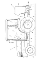
図1に本発明に係る農用トラクタの側面が、図2に背面図がそれぞれ示されている。この農用トラクタは、前輪2および後輪3が駆動されるキャビン付きのトラクタ本機1の後部に、油圧昇降されるリンク機構4を介してインプルメントの一例であるブームスプレーヤ5を連結し、トラクタ本機1から取り出したPTO動力でブームスプレーヤ5を駆動する散布機仕様に構成されている。
FIG. 1 shows a side view of an agricultural tractor according to the present invention, and FIG. 2 shows a rear view. In this agricultural tractor, a
図3に、この農用トラクタの伝動系の概略が示されている。機体前部に搭載されたエンジン6の出力は、主クラッチ7を介して静油圧式無段変速装置(HST)からなる主変速装置8に伝達され、主変速装置8からの変速動力がギヤ式の副変速機構9で複数段に変速された後、主推進車輪である後輪3と操向用の前輪2に伝達される。主変速装置8に入力されたエンジン動力の一部が、変速されることなくPTOクラッチ10を経てPTO軸11からライブPTO動力として取り出され、ブームスプレーヤ5の送出ポンプ12に軸伝達されるようになっている。
FIG. 3 shows an outline of the transmission system of this agricultural tractor. The output of the
副変速機構9の伝動下手に位置する適当な回転軸(例えば、最終変速軸)には回転センサ15が装備されており、図4に示すように、回転センサ15で検出された回転速度がトラクタ本機1に備えられたマイコン利用の主制御装置16に入力される。主制御装置16には、PTOクラッチ10の入り切り操作状態を検出するPTO検出センサ14、および、後輪3の外径情報を入力する車輪サイズ設定器18が接続されており、主制御装置16では、これらの検知情報に基づいてトラクタ本機1の走行速度Vが演算され、演算された走行速度Vに基づいてインプルメント制御用信号Eが出力される。
A suitable rotation shaft (for example, the final transmission shaft) located below the transmission of the
ブームスプレーヤ5には、薬剤貯留用のタンク19、PTO動力によって定速で駆動される前記送出ポンプ12、噴霧ノズル付きの起伏自在なブーム20、噴霧散布量を調整するバルブ機構21が装備されるとともに、その調整を行うためにマイコン利用の制御装置22が備えられている。図4に示すように、ブームスプレーヤ5の制御装置22には、バルブ機構21の開度を調整する電動モータあるいは電磁ソレノイドなどの電動アクチュエータ23、実バルブ開度を検出するフィードバック用の開度検出センサ24、単位面積当たりの散布量を人為的に調整設定する散布量設定器25、オン・オフスイッチ26、警報ランプやブザーなどの警報器27が接続されており、トラクタ本機1からのインプルメント制御用信号Eがコネクタ28を介して一線式に伝達されて、ブームスプレーヤ5の制御装置22に入力されるようになっている。
The
前記回転センサ15は、回転軸に備えられたギヤの外周に半導体磁気抵抗素子を対向配置して、ギヤ歯部の通過に応じてパルスを出力する仕様のものが用いられ、検出対象となる回転軸の回転速度に比例した周波数の高速パルスが出力されるようになっている。
The
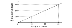
主制御装置16から出力されるインプルメント制御用信号Eは図6,図7に示すように、演算された走行速度Vに正比例した低い周波数のパルス信号であり、例えば、走行速度Vが2km/hでは20Hz、走行速度Vが4km/hでは40Hzでパルス信号が出力される。トラクタ本機1が走行停止している時には、極低周波(例えば0.002Hz)のインプルメント制御用信号Eが出力される(図5のフロー図参照)。
The implementation control signal E output from the
このように、走行停止している時にも極低周波のインプルメント制御用信号Eが出力されることで、ブームスプレーヤ5の制御装置22において、トラクタ本機1が走行停止して状態と、トラクタ本機1からインプルメント制御用信号Eが伝達されない状態とを認識することができ、インプルメント制御用信号Eが伝達されないことが判別されると、警報器27を作動させて信号伝達系でのコネクタ28のつなぎ忘れや断線の発生を認識することができるようになっている。
Thus, even when the traveling is stopped, the very low frequency implementation control signal E is output, so that in the control device 22 of the
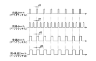
ここで、前進走行時におけるインプルメント制御用信号Eは小さいデューティd1(デューティ比)であるのに対して、後進走行時におけるインプルメント制御用信号Eは大きいデューティd2(デューティ比)に設定されている。PTOクラッチ10が入り状態にある時のインプルメント制御用信号Eは上記デューティd1又はd2(デューティ比)であるのに対して、PTOクラッチ10が切り状態にある時のインプルメント制御用信号Eは、前後進に関わらず更に大きいデューティd3(デューティ比)となるように設定されている。
Here, the implementation control signal E during forward travel has a small duty d1 (duty ratio), whereas the implementation control signal E during reverse travel has a large duty d2 (duty ratio). Yes. The implementation control signal E when the
インプルメント制御用信号Eを受けたブームスプレーヤ5の制御装置22においては、単位走行距離に対して散布量設定器25で設定された散布を行う目標バルブ開度が割り出され、実際のバルブ開度が目標バルブ開度になるように電動アクチュエータ23が作動制御され、トラクタ本機1の走行速度Vが変更されても所定の散布量での均一な薬剤噴霧散布が行われる。インプルメント制御用信号Eのデューティが大きいデューティd3(デューティ比)に変更されたことからPTOクラッチ10が切られたことが判別されると、直ちにバルブ機構21が閉じられて、薬剤のこぼれ落ちが防止されることになる。
In the control device 22 of the
農用トラクタのメーカーにおいては、トラクタ本機1の機種、車輪サイズに関わらず、同じ走行速度Vに対しては同じ周波数のパルス信号がインプルメント制御用信号Eとして出力されるように、主制御装置16が調整されて出荷され、同じメーカーのいずれのトラクタ本機1にインプルメントを連結しても、インプルメント側の制御装置22でトラクタ本機1の走行速度Vを演算する必要はなく、トラクタ本機1からのインプルメント制御用信号Eを、そのままでトラクタ本機1の走行速度Vを示す情報として利用することができる。
In the manufacturer of agricultural tractors, of type tractor the
〔他の実施例〕
(1)PTOクラッチ入り状態にある場合のインプルメント制御用信号Eを上記のように走行速度Vに正比例した周波数のパルス信号とし、PTOクラッチ切り状態が検出された場合のインプルメント制御用信号Eを、予め設定された作業用速度範囲から高速側に大きく外れた走行速度に相当する周波数のパルス信号とすることもできる。農用トラクタの作業用速度範囲は通常 0.1〜30(km/h)であるので、PTOクラッチ切り時に、例えば図8に示すように、実際に現出しない高速走行速度〔100(km/h)〕に相当する1000Hzのインプルメント制御用信号Eを出力して、インプルメント側でPTOクラッチ切り状態を認識できるようにして、バルブ機構21の閉じ制御に利用することもできる。
[Other Examples]
(1) The implementation control signal E when the PTO clutch is engaged is a pulse signal having a frequency directly proportional to the traveling speed V as described above, and the implementation control signal E when the PTO clutch disengagement state is detected. Can be a pulse signal having a frequency corresponding to a traveling speed greatly deviating from the preset working speed range to the high speed side. Since the working speed range of agricultural tractors is usually 0.1 to 30 (km / h), when the PTO clutch is disengaged, for example, as shown in FIG. 8, a high-speed traveling speed that does not actually appear [100 (km / h)] It is also possible to output the 1000 Hz implementation control signal E corresponding to the above, so that the implement side can recognize the PTO clutch disengaged state, and can be used for the closing control of the
(2)リンク機構4の昇降状態をトラクタ本機1におけるインプルメントに関わる作動状態として設定し、インプルメントが作業高さ範囲よりも上昇されたことが検知されると、上記のようにインプルメント制御用信号Eのデューティ(デューティ比)あるいは周波数を補正するように構成することもできる。これによると、トラクタ本機1が圃場の端に至って方向転換する際に、インプルメントを畦などにぶつけないように大きく上昇させた場合、補正されて送出されたインプルメント制御用信号Eからこの作動をインプルメント側で認識して、バルブ機構21の閉じ制御を行うことができる。
(2) When the lifting / lowering state of the link mechanism 4 is set as an operating state related to the implement in the tractor
(3)トラクタ本機1の設定角度以上の大きい機体操向状態をインプルメントに関わる作動状態として設定し、トラクタ本機1が大きく方向転換されたことが検知されると、上記のようにインプルメント制御用信号Eのデューティ(デューティ比)あるいは周波数を補正するように構成することもできる。これによると、トラクタ本機1が圃場の端に至って方向転換すると、補正されて送出されたインプルメント制御用信号Eからインプルメント側で機体方向転換であることを認識して、バルブ機構21の閉じ制御を行うことができる。
(3) A large body steering state larger than the set angle of the tractor
(4)トラクタ本機1の左右傾斜状態をトラクタ本機1におけるインプルメントに関わる作動状態として設定することもできる。上記のようにインプルメントがブームスプレーヤ5の場合、トラクタ本機1が左右に傾くとブーム19が作物や地面に接触するおそれがあるので、トラクタ本機1が設定以上に左右に傾斜したことが検知されると、走行速度情報を伝達するインプルメント制御用信号Eを補正して送出し、この補正されたインプルメント制御用信号Eからトラクタ本機1の左右傾斜を判別して、ブーム19の起伏揺動制御に利用する行うことが可能となる。
(4) The left-right inclined state of the tractor
(5)インプルメントに関わる作動状態を検知する対象を複数設定した場合、例えば、PTOクラッチ10の入り切り状態と、リンク機構4の昇降状態を共に検知するような場合には、補正したインプルメント制御用信号Eによっていずれの検知状態かを識別できるように、デューティ(デューティ比)あるいは周波数を差別化しておく必要がある。 (5) When a plurality of targets for detecting the operation state related to the implementation are set, for example, when both the on / off state of the PTO clutch 10 and the up / down state of the link mechanism 4 are detected, the corrected implementation control is performed. It is necessary to differentiate the duty (duty ratio) or the frequency so that the detection state can be identified by the signal E.
(6)インプルメントがブロードキャスタ(肥料散布)やライムソワ(石灰散布)などの粉粒状の散布剤を扱う散布装置の場合、定速駆動によって確実かつ十分な攪拌および散布を行い、インプルメント制御用信号Eに基づいてシャッタ開度の制御を行って均一な散布を行い、補正されたインプルメント制御用信号Eを認識してシャッタ閉じ制御を行うことができる。 (6) In the case of a spraying device that handles granular powders such as broadcasters (fertilizer spraying) or lime sowa (lime spraying), the implement performs agitation and spraying reliably at a constant speed to control the implementation. Based on the signal E, the shutter opening degree is controlled to perform uniform dispersion, and the corrected closing signal E can be recognized to perform the shutter closing control.
1 トラクタ本機
5 散布装置(インプルメント)
14 PTO検出センサ
16 主制御装置
21 バルブ機構
22 制御装置
E インプルメント制御用信号
V 走行速度
1
14
Claims (2)
PTOの入り切り状態を検出するPTO検出センサをトラクタ本機に備えると共に、
トラクタ本機に備えた主制御装置に、トラクタ本機の走行速度を割り出す演算手段と、割り出した走行速度の大きさに対応したインプルメント制御用信号を出力する出力手段と、前記PTO検出センサからの検出に基づいて前記インプルメント制御用信号を補正する出力補正手段とを備え、
前記出力補正手段により補正された前記インプルメント制御用信号に基づいて、前記散布装置に備えた制御装置においてPTOが切り状態であると判別されると、前記制御装置が前記シャッタ又はバルブを閉じ制御するように構成してある農用トラクタ。 A spraying device is provided as an implement, and the spraying device is provided with a shutter or a valve for blocking the supply of the stored spraying agent to the field,
The tractor unit is equipped with a PTO detection sensor for detecting the on / off state of the PTO,
From the PTO detection sensor , a calculation means for calculating the traveling speed of the tractor main unit, an output means for outputting an implement control signal corresponding to the determined traveling speed, Output correction means for correcting the implementation control signal based on the detection of
When the control device provided in the spraying device determines that the PTO is in the cut-off state based on the implementation control signal corrected by the output correcting means, the control device controls the shutter or valve to close. Agricultural tractor configured to do.
Priority Applications (1)
| Application Number | Priority Date | Filing Date | Title |
|---|---|---|---|
| JP2008128714A JP4568348B2 (en) | 2008-05-15 | 2008-05-15 | Agricultural tractor |
Applications Claiming Priority (1)
| Application Number | Priority Date | Filing Date | Title |
|---|---|---|---|
| JP2008128714A JP4568348B2 (en) | 2008-05-15 | 2008-05-15 | Agricultural tractor |
Related Parent Applications (1)
| Application Number | Title | Priority Date | Filing Date |
|---|---|---|---|
| JP2007043821A Division JP4568294B2 (en) | 2007-02-23 | 2007-02-23 | Agricultural tractor |
Publications (3)
| Publication Number | Publication Date |
|---|---|
| JP2008220383A JP2008220383A (en) | 2008-09-25 |
| JP2008220383A5 JP2008220383A5 (en) | 2009-01-08 |
| JP4568348B2 true JP4568348B2 (en) | 2010-10-27 |
Family
ID=39839702
Family Applications (1)
| Application Number | Title | Priority Date | Filing Date |
|---|---|---|---|
| JP2008128714A Active JP4568348B2 (en) | 2008-05-15 | 2008-05-15 | Agricultural tractor |
Country Status (1)
| Country | Link |
|---|---|
| JP (1) | JP4568348B2 (en) |
Families Citing this family (2)
| Publication number | Priority date | Publication date | Assignee | Title |
|---|---|---|---|---|
| JP5118076B2 (en) * | 2009-01-30 | 2013-01-16 | 株式会社クボタ | Pulse signal output structure of work equipment |
| JP5246514B2 (en) * | 2009-10-09 | 2013-07-24 | 株式会社タカキタ | Opening and closing shutter device for fertilizer drop port of fertilizer applicator |
Citations (5)
| Publication number | Priority date | Publication date | Assignee | Title |
|---|---|---|---|---|
| JPS6291104A (en) * | 1985-10-17 | 1987-04-25 | 井関農機株式会社 | Rolling controller of earth working machine |
| JPS63141513A (en) * | 1986-12-04 | 1988-06-14 | 株式会社クボタ | Control apparatus of working machine |
| JPH0236907U (en) * | 1988-08-31 | 1990-03-12 | ||
| JPH06141605A (en) * | 1992-11-04 | 1994-05-24 | Iseki & Co Ltd | Controller of working machine |
| JP2001088632A (en) * | 1999-08-06 | 2001-04-03 | Robert Bosch Gmbh | Signal generating system for superimposing information |
-
2008
- 2008-05-15 JP JP2008128714A patent/JP4568348B2/en active Active
Patent Citations (5)
| Publication number | Priority date | Publication date | Assignee | Title |
|---|---|---|---|---|
| JPS6291104A (en) * | 1985-10-17 | 1987-04-25 | 井関農機株式会社 | Rolling controller of earth working machine |
| JPS63141513A (en) * | 1986-12-04 | 1988-06-14 | 株式会社クボタ | Control apparatus of working machine |
| JPH0236907U (en) * | 1988-08-31 | 1990-03-12 | ||
| JPH06141605A (en) * | 1992-11-04 | 1994-05-24 | Iseki & Co Ltd | Controller of working machine |
| JP2001088632A (en) * | 1999-08-06 | 2001-04-03 | Robert Bosch Gmbh | Signal generating system for superimposing information |
Also Published As
| Publication number | Publication date |
|---|---|
| JP2008220383A (en) | 2008-09-25 |
Similar Documents
| Publication | Publication Date | Title |
|---|---|---|
| JP7150928B2 (en) | WORKING MACHINE CONTROL DEVICE, WORKING MACHINE CONTROL METHOD, AND WORKING MACHINE | |
| US8322482B2 (en) | Tractor ground positioning system | |
| US11800828B2 (en) | Working vehicle | |
| WO2021125273A1 (en) | Work vehicle | |
| US20240151009A1 (en) | Work machine and control method for work machine | |
| JP2020104617A (en) | Controller for work vehicle, work vehicle, and control method for work vehicle | |
| US9050890B2 (en) | Vehicle positioning system | |
| JP2012060899A (en) | Self-propelled pest control machine | |
| JP2006271320A (en) | Application controller for agricultural working vehicle | |
| JP4568348B2 (en) | Agricultural tractor | |
| JP6080338B2 (en) | Spraying machine | |
| JP4568349B2 (en) | Agricultural tractor with implement | |
| JP4568294B2 (en) | Agricultural tractor | |
| JP2008220383A5 (en) | ||
| JP4568268B2 (en) | Agricultural tractor | |
| JP2008206522A5 (en) | ||
| JP4568295B2 (en) | Agricultural tractor | |
| JP4568347B2 (en) | Agricultural tractor | |
| JP2014144008A (en) | Agricultural vehicle | |
| JP4568346B2 (en) | Agricultural tractor with implement | |
| JP2008245653A5 (en) | ||
| US11917933B2 (en) | Working vehicle | |
| JP5508073B2 (en) | Agricultural work vehicle | |
| JP2008237222A5 (en) | ||
| JP4568345B2 (en) | Agricultural tractor with implement |
Legal Events
| Date | Code | Title | Description |
|---|---|---|---|
| A521 | Written amendment |
Free format text: JAPANESE INTERMEDIATE CODE: A523 Effective date: 20081118 |
|
| A977 | Report on retrieval |
Free format text: JAPANESE INTERMEDIATE CODE: A971007 Effective date: 20090820 |
|
| A131 | Notification of reasons for refusal |
Free format text: JAPANESE INTERMEDIATE CODE: A131 Effective date: 20091203 |
|
| A521 | Written amendment |
Free format text: JAPANESE INTERMEDIATE CODE: A523 Effective date: 20100113 |
|
| TRDD | Decision of grant or rejection written | ||
| A01 | Written decision to grant a patent or to grant a registration (utility model) |
Free format text: JAPANESE INTERMEDIATE CODE: A01 Effective date: 20100708 |
|
| A01 | Written decision to grant a patent or to grant a registration (utility model) |
Free format text: JAPANESE INTERMEDIATE CODE: A01 |
|
| A61 | First payment of annual fees (during grant procedure) |
Free format text: JAPANESE INTERMEDIATE CODE: A61 Effective date: 20100806 |
|
| R150 | Certificate of patent or registration of utility model |
Free format text: JAPANESE INTERMEDIATE CODE: R150 Ref document number: 4568348 Country of ref document: JP Free format text: JAPANESE INTERMEDIATE CODE: R150 |
|
| FPAY | Renewal fee payment (event date is renewal date of database) |
Free format text: PAYMENT UNTIL: 20130813 Year of fee payment: 3 |
|
| FPAY | Renewal fee payment (event date is renewal date of database) |
Free format text: PAYMENT UNTIL: 20130813 Year of fee payment: 3 |
|
| FPAY | Renewal fee payment (event date is renewal date of database) |
Free format text: PAYMENT UNTIL: 20140813 Year of fee payment: 4 |