JP4142109B2 - Method and circuit device for transmitting rotational speed information and additional data - Google Patents
Method and circuit device for transmitting rotational speed information and additional data Download PDFInfo
- Publication number
- JP4142109B2 JP4142109B2 JP52510898A JP52510898A JP4142109B2 JP 4142109 B2 JP4142109 B2 JP 4142109B2 JP 52510898 A JP52510898 A JP 52510898A JP 52510898 A JP52510898 A JP 52510898A JP 4142109 B2 JP4142109 B2 JP 4142109B2
- Authority
- JP
- Japan
- Prior art keywords
- pulse
- additional data
- sensor
- rotational speed
- current
- Prior art date
- Legal status (The legal status is an assumption and is not a legal conclusion. Google has not performed a legal analysis and makes no representation as to the accuracy of the status listed.)
- Expired - Lifetime
Links
Images


Classifications
-
- G—PHYSICS
- G08—SIGNALLING
- G08C—TRANSMISSION SYSTEMS FOR MEASURED VALUES, CONTROL OR SIMILAR SIGNALS
- G08C15/00—Arrangements characterised by the use of multiplexing for the transmission of a plurality of signals over a common path
-
- B—PERFORMING OPERATIONS; TRANSPORTING
- B60—VEHICLES IN GENERAL
- B60C—VEHICLE TYRES; TYRE INFLATION; TYRE CHANGING; CONNECTING VALVES TO INFLATABLE ELASTIC BODIES IN GENERAL; DEVICES OR ARRANGEMENTS RELATED TO TYRES
- B60C23/00—Devices for measuring, signalling, controlling, or distributing tyre pressure or temperature, specially adapted for mounting on vehicles; Arrangement of tyre inflating devices on vehicles, e.g. of pumps or of tanks; Tyre cooling arrangements
- B60C23/02—Signalling devices actuated by tyre pressure
- B60C23/04—Signalling devices actuated by tyre pressure mounted on the wheel or tyre
-
- B—PERFORMING OPERATIONS; TRANSPORTING
- B60—VEHICLES IN GENERAL
- B60G—VEHICLE SUSPENSION ARRANGEMENTS
- B60G17/00—Resilient suspensions having means for adjusting the spring or vibration-damper characteristics, for regulating the distance between a supporting surface and a sprung part of vehicle or for locking suspension during use to meet varying vehicular or surface conditions, e.g. due to speed or load
- B60G17/015—Resilient suspensions having means for adjusting the spring or vibration-damper characteristics, for regulating the distance between a supporting surface and a sprung part of vehicle or for locking suspension during use to meet varying vehicular or surface conditions, e.g. due to speed or load the regulating means comprising electric or electronic elements
- B60G17/018—Resilient suspensions having means for adjusting the spring or vibration-damper characteristics, for regulating the distance between a supporting surface and a sprung part of vehicle or for locking suspension during use to meet varying vehicular or surface conditions, e.g. due to speed or load the regulating means comprising electric or electronic elements characterised by the use of a specific signal treatment or control method
-
- B—PERFORMING OPERATIONS; TRANSPORTING
- B60—VEHICLES IN GENERAL
- B60G—VEHICLE SUSPENSION ARRANGEMENTS
- B60G17/00—Resilient suspensions having means for adjusting the spring or vibration-damper characteristics, for regulating the distance between a supporting surface and a sprung part of vehicle or for locking suspension during use to meet varying vehicular or surface conditions, e.g. due to speed or load
- B60G17/015—Resilient suspensions having means for adjusting the spring or vibration-damper characteristics, for regulating the distance between a supporting surface and a sprung part of vehicle or for locking suspension during use to meet varying vehicular or surface conditions, e.g. due to speed or load the regulating means comprising electric or electronic elements
- B60G17/0195—Resilient suspensions having means for adjusting the spring or vibration-damper characteristics, for regulating the distance between a supporting surface and a sprung part of vehicle or for locking suspension during use to meet varying vehicular or surface conditions, e.g. due to speed or load the regulating means comprising electric or electronic elements characterised by the regulation being combined with other vehicle control systems
-
- B—PERFORMING OPERATIONS; TRANSPORTING
- B60—VEHICLES IN GENERAL
- B60T—VEHICLE BRAKE CONTROL SYSTEMS OR PARTS THEREOF; BRAKE CONTROL SYSTEMS OR PARTS THEREOF, IN GENERAL; ARRANGEMENT OF BRAKING ELEMENTS ON VEHICLES IN GENERAL; PORTABLE DEVICES FOR PREVENTING UNWANTED MOVEMENT OF VEHICLES; VEHICLE MODIFICATIONS TO FACILITATE COOLING OF BRAKES
- B60T8/00—Arrangements for adjusting wheel-braking force to meet varying vehicular or ground-surface conditions, e.g. limiting or varying distribution of braking force
- B60T8/17—Using electrical or electronic regulation means to control braking
- B60T8/171—Detecting parameters used in the regulation; Measuring values used in the regulation
-
- G—PHYSICS
- G01—MEASURING; TESTING
- G01P—MEASURING LINEAR OR ANGULAR SPEED, ACCELERATION, DECELERATION, OR SHOCK; INDICATING PRESENCE, ABSENCE, OR DIRECTION, OF MOVEMENT
- G01P3/00—Measuring linear or angular speed; Measuring differences of linear or angular speeds
- G01P3/42—Devices characterised by the use of electric or magnetic means
- G01P3/44—Devices characterised by the use of electric or magnetic means for measuring angular speed
- G01P3/48—Devices characterised by the use of electric or magnetic means for measuring angular speed by measuring frequency of generated current or voltage
- G01P3/481—Devices characterised by the use of electric or magnetic means for measuring angular speed by measuring frequency of generated current or voltage of pulse signals
- G01P3/489—Digital circuits therefor
Description
【0001】
【技術分野】
本発明は、切換え信号の形をし、回転速度センサによって供給されるデータと、追加データとを、共通の1本の信号ラインを経て伝送するための方法に関する。この方法を実施するための回路装置も同様に本発明に属する。
【0002】
【背景技術】
回転数センサは特に自動車技術において、多数の車両コントロールシステムの重要な入力量を得るために必要である。例えば公知のアンチロックコントロールシステム(ABS)、トラクションスリップコントロールシステム(TCS)及び走行安定性コントロールシステム(DSC,ASMS)は、個々の車輪の回転状態を絶えず測定及び評価することに基づいている。各々の車輪の回転速度データが検出され、ケーブルを経て電子評価装置に伝送される。
【0003】
きわめて異なる種類及び出力の回転速度センサが設けられている。自動車で使用されるセンサは基本的には、車輪と共に回転する、歯付きディスク、穴あきディスク等の形をしたエンコーダと、定置された測定値トランスデューサとからなっている。技術的及び価格的な理由から、従来は誘導式センサ又は測定値トランスデューサが多く使用された。この場合、エンコーダは車輪の回転運動に一致する切換え信号を生じる。切換え信号の周波数は回転速度情報を得るためにいろいろな方法で評価される。
【0004】
アクティブ回転速度センサが重要になってきている。このようなアクティブセンサはWO95/17680(P7805)に既に記載されている。このようなアクティブセンサの場合には、センサの定置された部分は、バイアス磁石としての働きをする永久磁石を備えた磁気抵抗性センサ要素と、電子回路を備えている。或るアクティブセンサは電源を必要とする。アクティブセンサの出力信号は2進信号であり、この2進信号は異なる振幅の供給電流からなっている。回転速度情報は周波数内にあるいは両電流レバルの間の変化に含まれる。この種の公知のセンサは、周波数が測定された回転数を示す方形波信号を生じる。
【0005】
個々で説明する種類の自動車コントロールシステムの場合には、製作コストが市販にとってきわめて重要である。すべての車輪の回転状態の検出、情報の伝送及び情報の評価のためのコストは比較的に高くつく。更に、例えばブレーキライニング摩耗、エンコーダとセンサの間の空隙、ブレーキ温度又はブレーキ液体温度、ブレーキ液状態等のような、各々の車輪で発生する、異なる種類の他の情報を検出し、評価回路に伝送しなければならない。
【0006】
【発明の開示】
【0007】
【発明が解決しようとする課題】
本発明の根底をなす課題は、車輪で感知された情報を測定及び評価するための全体コストと、車輪から評価回路への測定データの伝送のためのコスト(ケーブルコスト)を低減するかあるいは、別の見方では、個々の(アクティブ)センサと中央の評価回路の間の敷設ケーブルの利用を改善することである。
【0008】
【課題を解決するための手段】
この課題は請求項1記載の方法によって解決される。この方法の特徴は、設定された時間のパルスの列が、切換え信号から得られ、このパルスの間隔又はパルスセパレーションが回転速度情報を含み、パルスセパレーションで追加データが伝送され、個々のパルスによって追加データの伝送が開始されるか又は同期化されることにある。
【0009】
すなわち、本発明は、ケーブル(単線ケーブル又は2線ケーブル)が個々の車輪センサと中央の電子評価装置の間で、他の車輪データを伝送するためにも使用可能であり、本発明による方法が適用されるときにこの使用がいかなる追加コストも必要とせずに可能であるという認識に基づいている。この他の車輪データは例えば、ブレーキライニング摩耗、エンコーダと回転速度センサ要素(トランスデューサ)の間の空隙、車輪の温度、振動減衰装置の圧縮ストロークに関する車輪データ、タイヤ圧力、走行方向及び又は他の多くのデータである。
【0010】
本発明による方法の他の実施形では、追加データが2進信号の列又はビットの列に含まれ、この列が各々のセンサパルス又は同期パルスに続いて伝送される。その際、信号列又はビットの列の全体時間は好ましくは、最高回転速度のときに発生する、連続する回転速度センサパルスの間のパルスセパレーションよりも短い。
【0011】
更に、センサパルスのための時間軸と、追加データを含む2進信号のための時間軸が、共通のオシレータ回路又はクロックパルス発生器回路によって得られると有利であることが判った。その際、このようなオシレータの周波数精度を満足するにはわずかな要求で済む。
【0012】
更に、異なる振幅の供給された電流の形で回転速度情報を発生するアクティブセンサが回転速度測定のために使用され、追加データが、設定された振幅の電流によって伝送されると有利である。この場合、アクティブセンサを運転するために充分である電流基本値と、追加データを伝送するための中間の電流値と、センサパルスを示すための上側の電流値が伝送ラインで設定される。その際更に、伝送ラインの所定の電流最小値を下回ることと、電流最大値を上回ることが、エラー(ライン中断、アース又はバッテリ等に対する短絡等)の認識のために評価される。
【0013】
本発明による方法の一層に改善は、車輪停止認識時又は設定された時間を超えて回転速度パルスが存在しない時に、二次同期パルス又は補助同期パルスが発生させられ、この二次同期パルス又は補助同期パルスが追加データの伝送を開始する。すなわち、車両の停止時にも伝送及び評価される、ブレーキライニング磨耗表示や他の沢山のデータのような車輪データが生じる。
【0014】
しかし、車輪センサデータの伝送がプライオリティを有する。従って、本発明では、追加データの伝送中に、二次同期パルスによって開始されて、回転速度センサパルスが発生するときに、データの流れが中断され、センサパルスによって同期化されて新たに開始される。
【0015】
添付の従属請求項には、本発明の他の有利な実施形と、方法を実施するための回路装置が記載されている。
【0016】
本発明の他の詳細、特徴及び用途は、添付の図に基づく実施の形態の次の説明から明らかになる。
【0017】
【発明を実施するための最良の形態】
図面は簡略的及び象徴的な図である。
【0018】
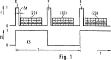
図1は本発明による方法の原理的な作動及び経過を説明するために役立つ。車輪と中央電子評価装置とを接続する伝送ラインにおける電流iの時間的な変化が示してある。勿論、このケーブルを介して、回転速度(回転数)情報だけでなく、ブレーキパッド摩耗表示装置及び又は特殊なセンサによって得られる付加的な情報が伝送される。
【0019】
図1のエンコーダ信号の変化は、定置された測定値トランスデューサ又は回転速度センサ(回転数センサ)と相対的なエンコーダの運動を、理想的な形で示している。値0と1の間で切り換えられ、その周波数又は周期Tが回転運動を示すこのような切換え信号(交番信号)は、回転速度センサの出力部に供される。アクティブセンサの場合には、0と1は供給された(負荷と無関係の)所定の電流信号又は電流レベルを示す。この電流信号又は電流レベルの振幅又は高さは公知のごとく、誘導性センサの出力電圧と異なり、回転速度とは無関係である。
【0020】
電流レベル0はアクティブセンサの機能又は運転のためにのみ充分である比較的に小さな電流値を示し、1は比較的に高い信号電流を示す。
【0021】
本発明では、信号の切換え0/1又は1/0の度に(信号発生器ホイール又はエンコーダのエッジ切換えの度に)回転速度センサパルスPが発生させられ、信号ラインに伝送される。これは、方形波信号(切換え信号)ESによる回転速度センサ情報の伝送と比較して、出力損失を大幅に低減することになる。
【0022】
連続する2つのセンサパルスPの間の小休止(セパレーション)において、本発明に従い、2進信号又はビット列Bt0〜Bt7からなる列の形をした追加データが伝送される。その際、各々のセンサパルスPは同時に、追加信号Bt0〜Bt7の伝送を開始する同期信号としての働きをする。センサパルスPと追加データBt0〜Bt7(ZD)を伝送するための異なる信号レベル又は電流振幅によって、回転速度センサデータ(ES)と追加データZD(Bt0〜Bt7)とが簡単に分離される。
【0023】
データ伝送ラインにおける瞬時の電流レベルは、伝送された回転速度データと追加データを識別するため、これらのデータを分離するため及びエラーを検出するために評価される。次に、これを図2に基づいて説明する。
【0024】
最小値Iminよりも低い小さすぎる電流又は最大値Imaxよりも高い大きすぎる電流が、エラー検出のために評価される。この最小値よりも大きくて許容誤差範囲IL内にある“電流基本値”はアクティブセンサの機能にとって充分である。すなわち、公知のごとく、アクティブセンサには絶えず電気エネルギーを供給しなければならない。許容誤差範囲IHI内にある“中間電流値”は追加データZD(Bt0〜Bt7)を伝送するために使用可能である。この上側には、図2に示すように、“上側の電流値”のための他の許容誤差範囲IH2が接続する。この上側の電流値はエッジ切換えの度に発生するセンサパルスのために空けてある。
【0025】
図1と関連して図2に示すように、本発明によって、センサデータと追加データを伝送するための簡単で、故障がなく、損失が少ない方法を実現することができる。
【0026】
本発明の他の特徴は、車両の停止時にも、非常に低い回転速度の時にも、追加データの伝送が達成されることにある。そのために、予め定めた時間Tを超えて回転速度センサパルスPが発生しないときには、補助同期信号が発生させられる。この補助同期信号はセンサパルスPと同様に、追加データZDの伝送を開始する。これは、ここで追加データと呼ぶ情報に属する情報があるからである。この情報は、車両の停止時にも伝送及び評価されるべきである。
【0027】
図3は車輪回転時(図3a)、車両停止時(車輪停止確認時)(図3b)及び非常に低い回転速度時(図3c)のときのデータ伝送を図示するために役立つ。追加データZDは0,1,2,3,4,5によって示してある。
【0028】
図3cの例では、回転速度センサパルスが長い時間発生せず、かつ補助同期パルスSy2による追加データ伝送が開始された後で、新たにセンサパルスPが発生する。センサパルスPによる同期はプライオリティを有し、図3cの状況で起こる追加データの伝送は中断され、かつセンサパルスPによって同期化されて新たに開始される。
【0029】
図3bと3cから判るように、補助同期パルスSy2の振幅は追加データ伝送のための許容誤差範囲IHI内にある。それによって、回転速度センサパルスPを補助同期パルスSy2から簡単に分離することができる。
【0030】
センサ電流信号ES(図1参照)の代わりに“狭い”、すなわち短いセンサ電流パルスPを使用することにより、アクティブセンサ及び電子評価回路内で、従来必要であった出力損失のほんの一部だけしか発生しない。それによって、全体寸法(チップスペース)ひいては製作コストが低下する。エンコーダの形状に従う元の信号(図1の方形波信号ES)は周波数を簡単に半分にすることにより、公知のごとく、評価回路内でエッジトリガフリップフロップによって再生可能である。センサ内での回転速度センサパルスPの発生は実際には問題なく可能である。というのは、このようなセンサはデータ処理及びデータ伝送のためにどっちみちオシレータを必要とするからである。
【0031】
回転速度センサパルスPの間の小休止の間、既に述べたように、追加データZDの伝送が行われる。この追加データ(例えば8ビット)は電流パルス(ビットパルス“0,1,2,3,4,5”)の形で伝送される。ビットのために論理状態1が伝送されると、このビットのために空けてあった時間の間、第3の電流レベルの電流パルスが発生させられる。そのために、好ましくは、基本レベルとセンサパルスの電流レベルの間にある電流範囲が、図2に基づいて説明したように決定される。
【0032】
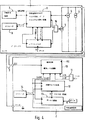
図4は本発明による方法を実施するための回路装置の実施の形態を示している。
【0033】
アクティブセンサに属する要素はブロック1内にまとめられ、伝送されたデータの評価のために必要な要素は他のブロック2にまとめられている。伝送ライン3はセンサブロック1と評価回路2を接続する。
【0034】
アクティブセンサ(1)の運転とデータ伝送のために必要な電流信号は、図に従って、象徴的に示した3個の電源4,5,6によって発生する。電源4は、センサの運転のために必要な例えば5mAの電流の基本値を発生する。追加データ(ZD)の伝送のために、例えば5mAの供給電流のための電源5が接続されている。本実施の形態では10mAの供給電流のために設計された第3の電源6は、ORゲート15によって電源5に加えて作用する。それによって、センサパルスPの持続時間のために、全体で20mAの供給電流が供される。
【0035】
回転速度検出のために、アクティブセンサ(1)の内部にはセンサ要素7が設けられている。このセンサ要素の出力信号はパルス発生回路と信号処理ユニット8によって、電源5だけあるいは電源5と6を作用させる。データパルスが予め定めた持続時間を有するので、センサブロック1内に、時間軸をなすオシレータ9が設けられている。製作コストを低減すべきときには、このようなオシレータは、供給電圧の大きな変動幅と大きな温度変化に基づいて、比較的に大きな周波数誤差を伴う。従って同様に、データパルスの持続時間は大きな誤差を伴う。それにもかかわらず、伝送されるセンサデータや追加データの確実な評価を可能にするために、前述のように、同期パルスが使用される。
【0036】
図1に基づいて既に説明した伝送プロトコルは特に有利である。回転速度センサパルスPは同時に、追加データZDの伝送のための同期パルスとして使用される。パルスPの立上りエッジには、上側の電流レベルIH2における滞在時間がが接続する。この滞在時間はセンサ1内の論理回路によって決まる予め設定された数のオシレータ周期の持続時間に一致する。センサパルス及び同期パルスPと追加データ伝送の間で、予め設定された短い時間Δt(図1参照)が保たれる。回転速度センサパルス及び同期パルスPのパルス幅と、データパルスBt0〜Bt7のパルス幅は、連続するパルスPの間の小休止が最も短い最高車輪回転数の場合にも、追加データBt0〜Bt7(ZD)の完全な伝送が可能であるように定められる。
【0037】
信号評価回路8は時間測定装置を備えている。この時間測定装置によって、同期パルスの幅が測定される。この時間測定に基づいて、伝送されたデータを回収するために、センサ電流信号が走査される。この場合、オシレータ9の周波数変動が、センサパルス及び同期パルスPと伝送されたデータBt0〜Bt7との間の時間的な間隔Δtと比較して遅いことが利用される。
【0038】
伝送された電流レベルの認識は評価回路2の回路ブロック10で行われる。電流が最小値Iminよりも低い場合あるいは最大値Imaxよりも高い場合、エラー(短絡、分路、ライン中断)の存在がORゲート11を介して信号化される。同期パルスP,Sy2の走査、すなわちこのパルスの認識とパルス時間の測定は、走査回路12によって行われる。追加データを検出するために、メモリ13が設けられている。回路12,13のための作動クロックは、オシレータ14によって発生する。メモリ13では伝送された追加データが検出され、出力部“データ”を経て他の処理のために供される。更に、伝送されたセンサ情報を更に案内するために出力部“回転数信号”が設けられている。伝送された電流振幅iが許容誤差範囲IH2内にあるときには、この出力部に常に信号が供給される。
【図面の簡単な説明】
【図1】伝送ラインでの伝送信号の時間的な変化、すなわちいわゆる伝送プロトコルを示す。
【図2】予め定められた電流限界値と電流レベルを示すグラフである。
【図3a】データ伝送に依存して伝送ラインにおける電流変化を示すための他のグラフである。
【図3b】データ伝送に依存して伝送ラインにおける電流変化を示すための他のグラフである。
【図3c】データ伝送に依存して伝送ラインにおける電流変化を示すための他のグラフである。
【図4】本発明による回路装置のブロック図である。
【符号の説明】
1 アクティヴセンサ
2 評価回路
3 伝送ライン
4 電源
5 電源
6 電源
7 センサ要素
8 信号評価回路
9 オシレータ
10 回路ブロック
11 ORゲート
12 走査回路
13 メモリ
14 オシレータ
15 ORゲート[0001]
【Technical field】
The present invention relates to a method for transmitting data supplied by a rotational speed sensor and additional data in the form of a switching signal via a common signal line. A circuit arrangement for carrying out this method also belongs to the invention.
[0002]
[Background]
Rotational speed sensors are necessary to obtain important input quantities for many vehicle control systems, especially in automotive technology. For example, known antilock control systems (ABS), traction slip control systems (TCS) and travel stability control systems (DSC, ASMS) are based on constantly measuring and evaluating the rotational state of individual wheels. The rotational speed data of each wheel is detected and transmitted to the electronic evaluation device via a cable.
[0003]
There are very different types and outputs of rotational speed sensors. Sensors used in automobiles basically consist of an encoder in the form of a toothed disk, perforated disk, etc., which rotates with the wheel, and a stationary measurement value transducer. For technical and cost reasons, inductive sensors or measurement transducers have been used in the past. In this case, the encoder produces a switching signal that matches the rotational movement of the wheels. The frequency of the switching signal is evaluated in various ways to obtain rotational speed information.
[0004]
Active rotational speed sensors are becoming important. Such active sensors are already described in WO 95/17680 (P7805). In the case of such an active sensor, the stationary part of the sensor comprises a magnetoresistive sensor element with a permanent magnet acting as a bias magnet and an electronic circuit. Some active sensors require a power source. The output signal of the active sensor is a binary signal, which consists of supply currents of different amplitudes. The rotation speed information is included in the frequency or in the change between both current levels. This type of known sensor produces a square wave signal indicative of the number of revolutions whose frequency has been measured.
[0005]
In the case of car control systems of the kind described individually, the production costs are very important for the market. The costs for detecting the rotational state of all wheels, transmitting information and evaluating information are relatively high. In addition, it detects other types of different information generated at each wheel, such as brake lining wear, air gap between encoder and sensor, brake temperature or brake fluid temperature, brake fluid condition, etc. Must be transmitted.
[0006]
DISCLOSURE OF THE INVENTION
[0007]
[Problems to be solved by the invention]
The problem underlying the present invention is to reduce the overall cost for measuring and evaluating the information sensed at the wheel and the cost for transmitting the measurement data from the wheel to the evaluation circuit (cable cost), or Another view is to improve the use of laying cables between individual (active) sensors and a central evaluation circuit.
[0008]
[Means for Solving the Problems]
This problem is solved by the method according to
[0009]
That is, the present invention can also be used for the transmission of other wheel data between individual wheel sensors and a central electronic evaluation device where a cable (single wire cable or two wire cable) is used. It is based on the recognition that this use is possible without the need for any additional costs when applied. This other wheel data includes, for example, brake lining wear, air gaps between the encoder and rotational speed sensor elements (transducers) , wheel temperature, wheel data relating to the compression stroke of the vibration damping device , tire pressure , direction of travel and / or many others. It is data of.
[0010]
In another embodiment of the method according to the invention, the additional data is contained in a binary signal sequence or bit sequence, which is transmitted following each sensor pulse or synchronization pulse. The total time of the signal train or bit train is then preferably shorter than the pulse separation between successive rotational speed sensor pulses that occurs at the maximum rotational speed.
[0011]
Furthermore, it has proved advantageous if the time axis for sensor pulses and the time axis for binary signals containing additional data are obtained by means of a common oscillator circuit or clock pulse generator circuit. At that time, only a few requirements are required to satisfy the frequency accuracy of such an oscillator.
[0012]
Furthermore, it is advantageous if an active sensor that generates rotational speed information in the form of supplied currents of different amplitudes is used for rotational speed measurement, and additional data is transmitted with currents of a set amplitude. In this case, a basic current value sufficient for operating the active sensor, an intermediate current value for transmitting additional data, and an upper current value for indicating a sensor pulse are set in the transmission line. In doing so, it is further evaluated for recognition of errors (line interruption, short circuit to earth or battery etc.) that the predetermined current minimum value of the transmission line is exceeded and that the current maximum value is exceeded.
[0013]
A further improvement of the method according to the invention is that a secondary synchronization pulse or auxiliary synchronization pulse is generated at the time of wheel stop recognition or when there is no rotational speed pulse for a set time and this secondary synchronization pulse or auxiliary The sync pulse starts transmitting additional data. That is, wheel data such as a brake lining wear display and other data that is transmitted and evaluated even when the vehicle is stopped.
[0014]
However, transmission of wheel sensor data has priority. Therefore, in the present invention, during the transmission of additional data, when the rotation speed sensor pulse is generated, which is started by the secondary synchronization pulse, the data flow is interrupted, synchronized by the sensor pulse, and newly started. The
[0015]
The appended dependent claims describe other advantageous embodiments of the invention and circuit arrangements for carrying out the method.
[0016]
Other details, features and applications of the invention will become apparent from the following description of an embodiment based on the attached figures.
[0017]
BEST MODE FOR CARRYING OUT THE INVENTION
The drawings are simplified and symbolic figures.
[0018]
FIG. 1 serves to illustrate the principle operation and course of the method according to the invention. The temporal change of the current i in the transmission line connecting the wheel and the central electronic evaluation device is shown. Of course, not only the rotation speed (rotation speed) information but also additional information obtained by the brake pad wear display device and / or a special sensor is transmitted via this cable.
[0019]
The change in the encoder signal in FIG. 1 shows in an ideal way the movement of the encoder relative to a stationary measured value transducer or rotational speed sensor (rotational speed sensor). Such a switching signal (alternating signal), which is switched between the
[0020]
A current level of 0 indicates a relatively small current value that is sufficient only for the function or operation of the active sensor, and 1 indicates a relatively high signal current.
[0021]
In the present invention, a rotational speed sensor pulse P is generated and transmitted to the signal line every time the signal is switched 0/1 or 1/0 (every time the signal generator wheel or encoder is switched). This significantly reduces output loss as compared with transmission of rotational speed sensor information by a square wave signal (switching signal) ES.
[0022]
In a short pause (separation) between two consecutive sensor pulses P, according to the invention, a binary signal or additional data in the form of a sequence of bit sequences Bt0 to Bt7 is transmitted. At this time, each sensor pulse P simultaneously serves as a synchronization signal for starting transmission of the additional signals Bt0 to Bt7. The rotational speed sensor data (ES) and the additional data ZD (Bt0 to Bt7) are easily separated by different signal levels or current amplitudes for transmitting the sensor pulse P and the additional data Bt0 to Bt7 (ZD).
[0023]
The instantaneous current level in the data transmission line is evaluated to distinguish between transmitted rotational speed data and additional data, to separate these data and to detect errors. Next, this will be described with reference to FIG.
[0024]
Currents that are too small below the minimum value I min or too large above the maximum value I max are evaluated for error detection. A “basic current value” that is larger than this minimum value and within the allowable error range I L is sufficient for the function of the active sensor. That is, as is well known, the active sensor must be constantly supplied with electrical energy. The “intermediate current value” within the allowable error range I HI can be used to transmit additional data ZD (Bt0 to Bt7). To this upper side, as shown in FIG. 2, another allowable error range I H2 for “upper current value” is connected. This upper current value is reserved for a sensor pulse that occurs every time the edge is switched.
[0025]
As shown in FIG. 2 in conjunction with FIG. 1, the present invention provides a simple, failure-free and loss-free method for transmitting sensor data and additional data.
[0026]
Another feature of the present invention is that the transmission of additional data is achieved both when the vehicle is stopped and at very low rotational speeds. Therefore, when the rotation speed sensor pulse P is not generated exceeding a predetermined time T, an auxiliary synchronization signal is generated. Similar to the sensor pulse P, this auxiliary synchronization signal starts transmission of additional data ZD. This is because there is information belonging to information called additional data here. This information should be transmitted and evaluated even when the vehicle is stopped.
[0027]
FIG. 3 is useful for illustrating data transmission during wheel rotation (FIG. 3a), vehicle stop (wheel stop confirmation) (FIG. 3b), and very low rotation speed (FIG. 3c). Additional data ZD is indicated by 0, 1, 2, 3, 4, and 5.
[0028]
In the example of FIG. 3c, the sensor pulse P is newly generated after the rotation speed sensor pulse is not generated for a long time and the additional data transmission by the auxiliary synchronization pulse Sy2 is started. The synchronization by the sensor pulse P has priority, the transmission of additional data occurring in the situation of FIG. 3c is interrupted and is newly initiated by being synchronized by the sensor pulse P.
[0029]
As can be seen from FIGS. 3b and 3c, the amplitude of the auxiliary synchronization pulse Sy2 is within the tolerance range I HI for additional data transmission. Thereby, the rotation speed sensor pulse P can be easily separated from the auxiliary synchronization pulse Sy2.
[0030]
By using a “narrow” or short sensor current pulse P instead of the sensor current signal ES (see FIG. 1), only a fraction of the output loss previously required within the active sensor and electronic evaluation circuit is achieved. Does not occur. Thereby, the overall dimensions (chip space) and thus the manufacturing costs are reduced. The original signal according to the shape of the encoder (square wave signal ES in FIG. 1) can be reproduced by an edge trigger flip-flop in the evaluation circuit, as is known, by simply halving the frequency. The generation of the rotation speed sensor pulse P in the sensor is actually possible without any problem. This is because such sensors both require an oscillator for data processing and data transmission.
[0031]
During the short pause between the rotational speed sensor pulses P, the additional data ZD is transmitted as already described. This additional data (for example, 8 bits) is transmitted in the form of current pulses (bit pulses “0, 1, 2, 3, 4, 5”). When a
[0032]
FIG. 4 shows an embodiment of a circuit arrangement for carrying out the method according to the invention.
[0033]
Elements belonging to the active sensor are grouped in
[0034]
The current signals necessary for the operation and data transmission of the active sensor (1) are generated by the three power sources 4, 5, 6 shown symbolically according to the figure. The power supply 4 generates a basic value of a current of, for example, 5 mA necessary for the operation of the sensor. For transmission of additional data (ZD), for example, a power supply 5 for a supply current of 5 mA is connected. In the present embodiment, the third power supply 6 designed for a supply current of 10 mA acts in addition to the power supply 5 by the
[0035]
A
[0036]
The transmission protocol already described with reference to FIG. 1 is particularly advantageous. The rotational speed sensor pulse P is simultaneously used as a synchronization pulse for transmission of the additional data ZD. Connected to the rising edge of the pulse P is the dwell time at the upper current level I H2 . This dwell time corresponds to the duration of a preset number of oscillator periods determined by the logic circuit in the
[0037]
The
[0038]
Recognition of the transmitted current level is performed in the
[Brief description of the drawings]
FIG. 1 shows a temporal change of a transmission signal on a transmission line, that is, a so-called transmission protocol.
FIG. 2 is a graph showing a predetermined current limit value and a current level.
FIG. 3a is another graph for showing current changes in a transmission line depending on data transmission.
FIG. 3b is another graph for showing current changes in a transmission line depending on data transmission.
FIG. 3c is another graph for showing current changes in a transmission line depending on data transmission.
FIG. 4 is a block diagram of a circuit device according to the present invention.
[Explanation of symbols]
DESCRIPTION OF
Claims (12)
通電電流の形で回転速度情報を発生するアクティブセンサ(1)が回転速度センサとして使用され、追加データ(ZD;Bt0〜Bt7;0・・・5)が同様に、設定された振幅の電流によって伝送され、アクティブセンサを運転するために充分である電流基本値(IL)と、追加データ(ZD;Bt0〜Bt7;0・・・5)を伝送するための中間の電流値(IH1)と、センサパルス(P)を示すための上側の電流値(IH2)が伝送ライン(3)で設定されていることを特徴とする方法。 In a method for transmitting data supplied by a rotational speed sensor and additional data in the form of a square wave signal (ES) via a common transmission line, a pulse of a period of a predetermined width ( P) is obtained from the square wave signal (ES), the interval between these pulses, ie pulse separation, contains rotational speed information, and additional data (ZD) is transmitted in the pulse separation, and individual pulses (P) The transmission of additional data (ZD; Bt0 to Bt7; 0... 5) is started or synchronized by the active sensor (1) which generates rotational speed information in the form of energization current and rotational speed. A current base that is used as a sensor and the additional data (ZD; Bt0 to Bt7; 0... 5) is likewise transmitted by a current of a set amplitude and is sufficient to operate an active sensor. (IL), an intermediate current value (IH1) for transmitting additional data (ZD; Bt0 to Bt7; 0... 5), and an upper current value (IH2) for indicating a sensor pulse (P) Is set in the transmission line (3).
追加データ(ZD)がビットの列(Bt0〜Bt7;0・・・5)に含まれ、この列が各々の回転速度センサパルス(P)に続いて伝送されること、及び
通電電流の形で回転速度情報を発生するアクティブセンサ(1)が回転速度センサとして使用され、追加データ(ZD;Bt0〜Bt7;0・・・5)が同様に、設定された振幅の電流によって伝送され、アクティブセンサを運転するために充分である電流基本値(IL)と、追加データ(ZD;Bt0〜Bt7;0・・・5)を伝送するための中間の電流値(IH1)と、センサパルス(P)を示すための上側の電流値(IH2)が伝送ライン(3)で設定されていることを特徴とする方法。 In a method for transmitting data supplied by a rotational speed sensor and additional data in the form of a square wave signal (ES) via a common transmission line, a pulse of a period of a predetermined width ( P) is obtained from the square wave signal (ES), the interval between these pulses, ie pulse separation, contains rotational speed information, and additional data (ZD) is transmitted in the pulse separation, and individual pulses (P) The transmission of additional data (ZD; Bt0 to Bt7; 0... 5) is started or synchronized by
Additional data (ZD) is included in a sequence of bits (Bt0 to Bt7; 0... 5), this sequence being transmitted following each rotational speed sensor pulse (P), and in the form of an energizing current. The active sensor (1) that generates the rotational speed information is used as the rotational speed sensor, and the additional data (ZD; Bt0 to Bt7; 0... 5) is similarly transmitted by the current having the set amplitude, and the active sensor. Current basic value (IL) which is sufficient to operate the vehicle, intermediate current value (IH1) for transmitting additional data (ZD; Bt0 to Bt7; 0... 5), and sensor pulse (P) A method characterized in that an upper current value (IH2) for indicating is set in the transmission line (3).
追加データ(ZD)がビットの列(Bt0〜Bt7;0・・・5)に含まれ、この列が各々の回転速度センサパルス(P)に続いて伝送されること、
追加データ(ZD)がビットの列(Bt0〜Bt7;0・・・5)に含まれ、この列の全体時間が、最高回転速度のときに発生する、連続する回転速度センサパルス(P)の間のパルスセパレーションよりも短いこと、及び
通電電流の形で回転速度情報を発生するアクティブセンサ(1)が回転速度センサとして使用され、追加データ(ZD;Bt0〜Bt7;0・・・5)が同様に、設定された振幅の電流によって伝送され、アクティブセンサを運転するために充分である電流基本値(IL)と、追加データ(ZD;Bt0〜Bt7;0・・・5)を伝送するための中間の電流値(IH1)と、センサパルス(P)を示すための上側の電流値(IH2)が伝送ライン(3)で設定されていることを特徴とする方法。 In a method for transmitting data supplied by a rotational speed sensor and additional data in the form of a square wave signal (ES) via a common transmission line, a pulse of a period of a predetermined width ( P) is obtained from the square wave signal (ES), the interval between these pulses, ie pulse separation, contains rotational speed information, and additional data (ZD) is transmitted in the pulse separation, and individual pulses (P) The transmission of additional data (ZD; Bt0 to Bt7; 0... 5) is started or synchronized by
Additional data (ZD) is included in a string of bits (Bt0 to Bt7; 0... 5), which is transmitted following each rotational speed sensor pulse (P),
Additional data (ZD) is included in the bit string (Bt0 to Bt7; 0... 5), and the total time of this string is the continuous rotation speed sensor pulse (P) generated at the maximum rotation speed. The active sensor (1) that generates the rotational speed information in the form of an energization current is used as the rotational speed sensor, and additional data (ZD; Bt0 to Bt7; 0... 5) is used. Similarly, to transmit the current basic value (IL) transmitted by the current of the set amplitude and sufficient to operate the active sensor and additional data (ZD; Bt0 to Bt7; 0... 5). The intermediate current value (IH1) and the upper current value (IH2) for indicating the sensor pulse (P) are set in the transmission line (3).
Applications Claiming Priority (3)
| Application Number | Priority Date | Filing Date | Title |
|---|---|---|---|
| DE19650935.1 | 1996-12-07 | ||
| DE19650935A DE19650935A1 (en) | 1996-12-07 | 1996-12-07 | Method and circuit arrangement for the transmission of speed information and additional data |
| PCT/EP1997/006209 WO1998025148A2 (en) | 1996-12-07 | 1997-11-08 | Method and circuit for transmitting information on rotational speed and additional data |
Publications (3)
| Publication Number | Publication Date |
|---|---|
| JP2001505691A JP2001505691A (en) | 2001-04-24 |
| JP2001505691A5 JP2001505691A5 (en) | 2005-06-16 |
| JP4142109B2 true JP4142109B2 (en) | 2008-08-27 |
Family
ID=7814005
Family Applications (1)
| Application Number | Title | Priority Date | Filing Date |
|---|---|---|---|
| JP52510898A Expired - Lifetime JP4142109B2 (en) | 1996-12-07 | 1997-11-08 | Method and circuit device for transmitting rotational speed information and additional data |
Country Status (5)
| Country | Link |
|---|---|
| US (1) | US6687644B1 (en) |
| EP (1) | EP0944888B1 (en) |
| JP (1) | JP4142109B2 (en) |
| DE (2) | DE19650935A1 (en) |
| WO (1) | WO1998025148A2 (en) |
Cited By (6)
| Publication number | Priority date | Publication date | Assignee | Title |
|---|---|---|---|---|
| US10216559B2 (en) | 2016-11-14 | 2019-02-26 | Allegro Microsystems, Llc | Diagnostic fault communication |
| US10481218B2 (en) | 2016-09-08 | 2019-11-19 | Allegro Microsystems, Llc | Providing information about a target object in a formatted output signal |
| US10495700B2 (en) | 2016-01-29 | 2019-12-03 | Allegro Microsystems, Llc | Method and system for providing information about a target object in a formatted output signal |
| US10495485B2 (en) | 2016-05-17 | 2019-12-03 | Allegro Microsystems, Llc | Magnetic field sensors and output signal formats for a magnetic field sensor |
| US11368533B2 (en) | 2020-11-19 | 2022-06-21 | Allegro Microsystems, Llc | Signaling between master and one or more slave components to share absolute and incremental data |
| US11686597B2 (en) | 2019-06-07 | 2023-06-27 | Allegro Microsystems, Llc | Magnetic field sensors and output signal formats for magnetic field sensors |
Families Citing this family (114)
| Publication number | Priority date | Publication date | Assignee | Title |
|---|---|---|---|---|
| DE19808575A1 (en) * | 1997-11-25 | 1999-05-27 | Itt Mfg Enterprises Inc | Signal processing method for encoded data |
| US6731224B1 (en) | 1997-11-25 | 2004-05-04 | Continental Teves Ag & Co., Ohg | Method and device for preprocessing a received, data coded transmitting signal |
| DE19911774B4 (en) * | 1998-03-20 | 2013-12-24 | Continental Teves Ag & Co. Ohg | Sensor arrangement for detecting movements |
| DE19849408A1 (en) * | 1998-10-27 | 2000-05-04 | Continental Teves Ag & Co Ohg | Method and device for processing a received signal that transmits data in coded form |
| JP3685940B2 (en) * | 1999-02-01 | 2005-08-24 | 日信工業株式会社 | Fault diagnosis device for wheel speed input system in vehicle motion control device |
| DE19937155A1 (en) | 1999-08-06 | 2001-03-15 | Bosch Gmbh Robert | System for generating a signal for superimposing information |
| JP4964358B2 (en) * | 1999-12-07 | 2012-06-27 | 株式会社デンソー | Rotation sensor detection signal processing apparatus and rotation sensor detection signal output method |
| DE10062839A1 (en) * | 2000-07-06 | 2002-01-17 | Continental Teves Ag & Co Ohg | Arrangements and methods for the detection and transmission of sensor signals in motor vehicles, and sensor |
| JP2002104149A (en) | 2000-09-29 | 2002-04-10 | Toyota Motor Corp | Rotating state detecting device for wheel |
| DE10150760A1 (en) * | 2000-12-06 | 2002-08-14 | Continental Teves Ag & Co Ohg | Measurement of wheel rotational velocity and tire pressure for use in a motor vehicle control system, with velocity and pressure signals transmitted over the same interface so that additional hardware is not required |
| DE10119471A1 (en) * | 2001-04-20 | 2002-10-31 | Micronas Gmbh | Method and two-wire sensor for measuring a physical quantity |
| WO2002090999A1 (en) * | 2001-05-10 | 2002-11-14 | Continental Teves Ag & Co. Ohg | Wheel speed sensor arrangement with transmission of additional information |
| US6815944B2 (en) * | 2002-01-31 | 2004-11-09 | Allegro Microsystems, Inc. | Method and apparatus for providing information from a speed and direction sensor |
| JP4200796B2 (en) * | 2003-03-24 | 2008-12-24 | 株式会社アドヴィックス | Brake noise detector |
| JP2005128998A (en) * | 2003-09-30 | 2005-05-19 | Aisin Seiki Co Ltd | Rotation detecting device |
| JP2005241268A (en) | 2004-02-24 | 2005-09-08 | Aisin Seiki Co Ltd | Rotation sensor |
| JP4605435B2 (en) * | 2004-03-24 | 2011-01-05 | アイシン精機株式会社 | Rotation detector |
| US7365530B2 (en) | 2004-04-08 | 2008-04-29 | Allegro Microsystems, Inc. | Method and apparatus for vibration detection |
| DE102004034865A1 (en) | 2004-07-19 | 2006-02-16 | Siemens Ag | Sensor for measuring the position of an actuator |
| JP4609000B2 (en) * | 2004-08-26 | 2011-01-12 | 日立電線株式会社 | Magnetic motion sensor |
| DE102004059202A1 (en) * | 2004-12-09 | 2006-06-14 | Ab Skf | Data generating and outputting device for vehicle, has output unit arranged for output of revolution speed information and of data of additional sensor in the form of pulse flanks that are characterized by two different signal levels |
| US7253614B2 (en) | 2005-03-21 | 2007-08-07 | Allegro Microsystems, Inc. | Proximity detector having a sequential flow state machine |
| JP5011761B2 (en) * | 2006-03-10 | 2012-08-29 | パナソニック株式会社 | Strain detector |
| WO2008004926A1 (en) * | 2006-07-07 | 2008-01-10 | Mecel Engine Systems Aktiebolag | Control system and method for transmitting sensor signals for a combustion engine |
| US8237431B2 (en) * | 2007-07-05 | 2012-08-07 | Terry Fruehling | Wheel speed sensor |
| DE102007048284A1 (en) * | 2007-09-27 | 2009-04-09 | Continental Automotive Gmbh | Speed data transmission device |
| WO2009069021A1 (en) * | 2007-11-28 | 2009-06-04 | Nxp B.V. | Sensor device for detecting movement |
| WO2009087503A1 (en) * | 2008-01-04 | 2009-07-16 | Nxp B.V. | Sensor device |
| US9823090B2 (en) | 2014-10-31 | 2017-11-21 | Allegro Microsystems, Llc | Magnetic field sensor for sensing a movement of a target object |
| US8624588B2 (en) | 2008-07-31 | 2014-01-07 | Allegro Microsystems, Llc | Apparatus and method for providing an output signal indicative of a speed of rotation and a direction of rotation as a ferromagnetic object |
| US8122159B2 (en) | 2009-01-16 | 2012-02-21 | Allegro Microsystems, Inc. | Determining addresses of electrical components arranged in a daisy chain |
| US8022692B2 (en) | 2009-01-19 | 2011-09-20 | Allegro Microsystems, Inc. | Direction detection sensor |
| DE112010000848B4 (en) | 2009-02-17 | 2018-04-05 | Allegro Microsystems, Llc | Circuits and methods for generating a self-test of a magnetic field sensor |
| JP5218854B2 (en) * | 2009-05-28 | 2013-06-26 | アイシン精機株式会社 | Data communication method and wheel state detection device |
| JP5218855B2 (en) * | 2009-06-03 | 2013-06-26 | アイシン精機株式会社 | Data communication method and wheel state detection device |
| JP5278255B2 (en) * | 2009-09-02 | 2013-09-04 | アイシン精機株式会社 | Data communication method and data communication apparatus |
| US9250258B2 (en) | 2010-06-10 | 2016-02-02 | Continental Teves Ag & Co. Ohg | Sensor arrangement for speed measurement |
| EP2583471B1 (en) | 2010-06-15 | 2019-08-07 | Continental Teves AG & Co. OHG | Method for synchronizing sensors |
| DE102010025872A1 (en) | 2010-07-02 | 2012-01-05 | Schaeffler Technologies Gmbh & Co. Kg | Method and arrangement for transmitting sensor signals |
| US8729890B2 (en) | 2011-04-12 | 2014-05-20 | Allegro Microsystems, Llc | Magnetic angle and rotation speed sensor with continuous and discontinuous modes of operation based on rotation speed of a target object |
| US8793085B2 (en) | 2011-08-19 | 2014-07-29 | Allegro Microsystems, Llc | Circuits and methods for automatically adjusting a magnetic field sensor in accordance with a speed of rotation sensed by the magnetic field sensor |
| US9817078B2 (en) | 2012-05-10 | 2017-11-14 | Allegro Microsystems Llc | Methods and apparatus for magnetic sensor having integrated coil |
| US9329057B2 (en) | 2012-05-31 | 2016-05-03 | Allegro Microsystems, Llc | Gear tooth sensor with peak and threshold detectors |
| US9068859B2 (en) | 2012-06-18 | 2015-06-30 | Allegro Microsystems, Llc | Magnetic field sensors and related techniques provide a self-test by communicating selected analog or digital samples of a proximity signal |
| US9222990B2 (en) | 2012-06-18 | 2015-12-29 | Allegro Microsystems, Llc | Magnetic field sensors and related techniques that can communicate at least one of three or more potential categories in which one or more characteristic values of a proximity signal responsive to a proximity of a sensed object are categorized |
| US8754640B2 (en) | 2012-06-18 | 2014-06-17 | Allegro Microsystems, Llc | Magnetic field sensors and related techniques that can provide self-test information in a formatted output signal |
| US8860404B2 (en) | 2012-06-18 | 2014-10-14 | Allegro Microsystems, Llc | Magnetic field sensors and related techniques that can provide a self-test using signals and related thresholds |
| EP2693221B1 (en) | 2012-07-30 | 2017-04-26 | Nxp B.V. | Magnetic Sensor Arrangement |
| US9031769B2 (en) | 2012-09-05 | 2015-05-12 | Infineon Technologies Ag | Sensor current interface transceiver with adaptive linearization |
| US9031738B2 (en) | 2013-01-24 | 2015-05-12 | Trw Automotive U.S. Llc | Method and apparatus for determining tire condition and location using wheel speed sensors and acceleration sensors |
| US9973835B2 (en) * | 2013-01-28 | 2018-05-15 | Infineon Technologies Ag | Signal generator, a decoder, a method for generating a transmit signal and a method for determining speed data |
| US10026306B2 (en) * | 2013-01-28 | 2018-07-17 | Infineon Technologies Ag | Signal generator, decoder, method for generating a transmit signal and method for determining speed data |
| US9201435B2 (en) | 2013-03-05 | 2015-12-01 | Infineon Technologies Ag | System and method for a power supply |
| US10725100B2 (en) | 2013-03-15 | 2020-07-28 | Allegro Microsystems, Llc | Methods and apparatus for magnetic sensor having an externally accessible coil |
| EP2999943B1 (en) | 2013-06-20 | 2022-04-06 | Allegro MicroSystems, LLC | System and method for providing signal encoding representative of a signature region in a target and of a direction of rotation |
| US9810519B2 (en) | 2013-07-19 | 2017-11-07 | Allegro Microsystems, Llc | Arrangements for magnetic field sensors that act as tooth detectors |
| US10145908B2 (en) | 2013-07-19 | 2018-12-04 | Allegro Microsystems, Llc | Method and apparatus for magnetic sensor producing a changing magnetic field |
| US10495699B2 (en) | 2013-07-19 | 2019-12-03 | Allegro Microsystems, Llc | Methods and apparatus for magnetic sensor having an integrated coil or magnet to detect a non-ferromagnetic target |
| US9634715B2 (en) | 2014-02-18 | 2017-04-25 | Allegro Microsystems, Llc | Signaling between master and slave components using a shared communication node of the master component |
| US9172565B2 (en) | 2014-02-18 | 2015-10-27 | Allegro Microsystems, Llc | Signaling between master and slave components using a shared communication node of the master component |
| US9787495B2 (en) | 2014-02-18 | 2017-10-10 | Allegro Microsystems, Llc | Signaling between master and slave components using a shared communication node of the master component |
| US9851416B2 (en) | 2014-07-22 | 2017-12-26 | Allegro Microsystems, Llc | Systems and methods for magnetic field sensors with self-test |
| US10156461B2 (en) | 2014-10-31 | 2018-12-18 | Allegro Microsystems, Llc | Methods and apparatus for error detection in a magnetic field sensor |
| US10712403B2 (en) | 2014-10-31 | 2020-07-14 | Allegro Microsystems, Llc | Magnetic field sensor and electronic circuit that pass amplifier current through a magnetoresistance element |
| US9720054B2 (en) | 2014-10-31 | 2017-08-01 | Allegro Microsystems, Llc | Magnetic field sensor and electronic circuit that pass amplifier current through a magnetoresistance element |
| US9823092B2 (en) | 2014-10-31 | 2017-11-21 | Allegro Microsystems, Llc | Magnetic field sensor providing a movement detector |
| US9719806B2 (en) | 2014-10-31 | 2017-08-01 | Allegro Microsystems, Llc | Magnetic field sensor for sensing a movement of a ferromagnetic target object |
| US10466298B2 (en) | 2014-11-14 | 2019-11-05 | Allegro Microsystems, Llc | Magnetic field sensor with shared path amplifier and analog-to-digital-converter |
| US9804249B2 (en) | 2014-11-14 | 2017-10-31 | Allegro Microsystems, Llc | Dual-path analog to digital converter |
| US10041810B2 (en) | 2016-06-08 | 2018-08-07 | Allegro Microsystems, Llc | Arrangements for magnetic field sensors that act as movement detectors |
| US10260905B2 (en) | 2016-06-08 | 2019-04-16 | Allegro Microsystems, Llc | Arrangements for magnetic field sensors to cancel offset variations |
| US10012518B2 (en) | 2016-06-08 | 2018-07-03 | Allegro Microsystems, Llc | Magnetic field sensor for sensing a proximity of an object |
| DE102016113249A1 (en) * | 2016-07-19 | 2018-01-25 | Knorr-Bremse Systeme für Nutzfahrzeuge GmbH | Vehicle with traction help |
| DE102016125183B4 (en) * | 2016-12-21 | 2022-01-27 | Infineon Technologies Ag | Devices for encoding and decoding wheel speed sensor signals and methods for communicating encoded wheel speed sensor signals |
| US10310028B2 (en) | 2017-05-26 | 2019-06-04 | Allegro Microsystems, Llc | Coil actuated pressure sensor |
| US11428755B2 (en) | 2017-05-26 | 2022-08-30 | Allegro Microsystems, Llc | Coil actuated sensor with sensitivity detection |
| US10641842B2 (en) | 2017-05-26 | 2020-05-05 | Allegro Microsystems, Llc | Targets for coil actuated position sensors |
| US10324141B2 (en) | 2017-05-26 | 2019-06-18 | Allegro Microsystems, Llc | Packages for coil actuated position sensors |
| US10996289B2 (en) | 2017-05-26 | 2021-05-04 | Allegro Microsystems, Llc | Coil actuated position sensor with reflected magnetic field |
| US10837943B2 (en) | 2017-05-26 | 2020-11-17 | Allegro Microsystems, Llc | Magnetic field sensor with error calculation |
| US10473486B2 (en) | 2017-07-20 | 2019-11-12 | Allegro Microsystems, Llc | Duty cycle of an output signal of a magnetic field sensor to detect speed and direction of angular rotation of a rotating magnetic structure or a fault |
| US10598514B2 (en) | 2017-07-20 | 2020-03-24 | Allegro Microsystems, Llc | Magnetic field sensor to detect speed of angular rotation of a rotating magnetic structure, direction of the rotating magnetic structure or fault |
| US10571301B2 (en) | 2017-07-20 | 2020-02-25 | Allegro Microsystems, Llc | Frequency of an output signal of a magnetic field sensor to detect speed and direction of angular rotation of a rotating magnetic structure or a fault |
| US10480957B2 (en) | 2017-07-20 | 2019-11-19 | Allegro Microsystems, Llc | Magnetic field sensor to detect direction of angular rotation of a rotating magnetic structure, speed of the rotating magnetic structure or fault |
| US10436606B2 (en) | 2017-07-20 | 2019-10-08 | Allegro Microsystems, Llc | Magnetic field sensor to detect speed and direction of angular rotation of a rotating magnetic structure |
| US10900814B2 (en) * | 2017-09-07 | 2021-01-26 | Infineon Technologies Ag | Magnetic sensor for system-level diagnostics |
| DE102017222799A1 (en) * | 2017-12-14 | 2019-06-19 | Continental Teves Ag & Co. Ohg | Monitoring device, method of monitoring and use |
| DE102018222791B4 (en) * | 2017-12-22 | 2024-02-01 | Continental Automotive Technologies GmbH | Speed sensor with increased resolution and multiple switching thresholds |
| US10866117B2 (en) | 2018-03-01 | 2020-12-15 | Allegro Microsystems, Llc | Magnetic field influence during rotation movement of magnetic target |
| US10747708B2 (en) | 2018-03-08 | 2020-08-18 | Allegro Microsystems, Llc | Communication system between electronic devices |
| US10656170B2 (en) | 2018-05-17 | 2020-05-19 | Allegro Microsystems, Llc | Magnetic field sensors and output signal formats for a magnetic field sensor |
| US10725122B2 (en) | 2018-07-20 | 2020-07-28 | Allegro Microsystems, Llc | Ratiometric sensor output topology and methods |
| US11255700B2 (en) | 2018-08-06 | 2022-02-22 | Allegro Microsystems, Llc | Magnetic field sensor |
| DE102018122881A1 (en) * | 2018-09-18 | 2020-03-19 | Knorr-Bremse Systeme für Nutzfahrzeuge GmbH | Method for transmitting sensor signals from sensors of a vehicle brake and vehicle brake with a sensor arrangement with at least two sensors |
| DE102018217626A1 (en) * | 2018-10-15 | 2020-04-16 | Continental Teves Ag & Co. Ohg | Wheel speed sensor with constant log frequency |
| US10823586B2 (en) | 2018-12-26 | 2020-11-03 | Allegro Microsystems, Llc | Magnetic field sensor having unequally spaced magnetic field sensing elements |
| US11061084B2 (en) | 2019-03-07 | 2021-07-13 | Allegro Microsystems, Llc | Coil actuated pressure sensor and deflectable substrate |
| US10955306B2 (en) | 2019-04-22 | 2021-03-23 | Allegro Microsystems, Llc | Coil actuated pressure sensor and deformable substrate |
| US11125590B2 (en) | 2019-05-07 | 2021-09-21 | Allegro Microsystems, Llc | System and method for vibration detection with direction change response immunity using a magnetic field sensor |
| US11029176B2 (en) | 2019-05-07 | 2021-06-08 | Allegro Microsystems, Llc | System and method for vibration detection with no loss of position information using a magnetic field sensor |
| DE102019119620A1 (en) | 2019-07-19 | 2021-01-21 | WABCO Global GmbH | Rotation sensor as well as vehicle |
| US11280637B2 (en) | 2019-11-14 | 2022-03-22 | Allegro Microsystems, Llc | High performance magnetic angle sensor |
| US11237020B2 (en) | 2019-11-14 | 2022-02-01 | Allegro Microsystems, Llc | Magnetic field sensor having two rows of magnetic field sensing elements for measuring an angle of rotation of a magnet |
| US11942831B2 (en) | 2020-01-15 | 2024-03-26 | Allegro Microsystems, Llc | Three-phase BLDC motor driver/controller having diagnostic signal processing |
| US11194004B2 (en) | 2020-02-12 | 2021-12-07 | Allegro Microsystems, Llc | Diagnostic circuits and methods for sensor test circuits |
| US11262422B2 (en) | 2020-05-08 | 2022-03-01 | Allegro Microsystems, Llc | Stray-field-immune coil-activated position sensor |
| US11029370B1 (en) | 2020-05-22 | 2021-06-08 | Allegro Microsystems, Llc | Sensor output control methods and apparatus |
| US11493361B2 (en) | 2021-02-26 | 2022-11-08 | Allegro Microsystems, Llc | Stray field immune coil-activated sensor |
| US11885645B2 (en) | 2021-06-17 | 2024-01-30 | Allegro Microsystems, Llc | Supply voltage configurable sensor |
| US11578997B1 (en) | 2021-08-24 | 2023-02-14 | Allegro Microsystems, Llc | Angle sensor using eddy currents |
| DE102021212324A1 (en) * | 2021-11-02 | 2023-05-04 | Continental Automotive Technologies GmbH | Method for evaluating wheel sensor signals, arrangement for this and braking system comprising the arrangement |
| US20230152344A1 (en) * | 2021-11-17 | 2023-05-18 | Infineon Technologies Ag | Method for reducing a microbreak memory area and enhanced timing scheme for freezing microbreak feature for a speed sensor |
| US11848682B2 (en) | 2022-01-11 | 2023-12-19 | Allegro Microsystems, Llc | Diagnostic circuits and methods for analog-to-digital converters |
| US20230400477A1 (en) | 2022-05-18 | 2023-12-14 | Allegro Microsystems, Llc | High resolution sensing protocol |
Family Cites Families (14)
| Publication number | Priority date | Publication date | Assignee | Title |
|---|---|---|---|---|
| DE2242639C3 (en) | 1972-08-30 | 1980-01-17 | Siemens Ag, 1000 Berlin Und 8000 Muenchen | Time division multiplex telegraphy system for character-by-character interleaving |
| DE3615452A1 (en) * | 1986-05-07 | 1987-11-26 | Endress Hauser Gmbh Co | ARRANGEMENT FOR TRANSMITTING SIGNALS IN A MEASURING ARRANGEMENT |
| DE3843062A1 (en) * | 1988-12-21 | 1990-06-28 | Siemens Ag | COMBINED MEASUREMENT VALUE RECORDING AND TRANSMISSION OF MEASUREMENT VALUES ON A BUS LINE |
| US5231872A (en) * | 1991-02-21 | 1993-08-03 | Ttc/Truck Tech Corp. | Tire monitoring apparatus and method |
| DE4309989A1 (en) * | 1992-03-30 | 1993-10-14 | Heraeus Sensor Gmbh | Temp. telemetering device using constant current pulses - includes evaluation unit with controllable switch for producing synchronisation pulse detectable by each remote sensing unit |
| DE4323619C1 (en) * | 1993-07-15 | 1994-08-18 | Daimler Benz Ag | Apparatus for the transmission of a plurality of sensor signals to an electronic control device |
| US5998989A (en) * | 1993-12-22 | 1999-12-07 | Itt Automotive Europe Gmbh | Device including magnet-biased magnetoresistive sensor and rotatable, magnetized encoder for detecting rotary movements |
| FR2723037A1 (en) * | 1994-08-01 | 1996-02-02 | Michelin & Cie | DEVICE FOR MONITORING THE CONDITION OF THE TIRES AND OF THE BRAKE TEMPERATURE OF A VEHICLE |
| DE19504822C1 (en) * | 1995-02-14 | 1996-09-26 | Hirschmann Richard Gmbh | Device for monitoring at least two state variables of a motor vehicle |
| DE19517437C2 (en) * | 1995-05-12 | 1997-08-07 | Lenze Gmbh & Co Kg Aerzen | Method and device for transmitting incremental angle or path information |
| DE19523940A1 (en) * | 1995-07-05 | 1997-01-09 | Bosch Gmbh Robert | Brake lining wear measurement system for motor vehicles - produces signal denoting rpm of vehicle wheel and signal representing wear of vehicle brake, signals superimposed on each other and carried by one cable to control unit |
| DE19536006C2 (en) * | 1995-09-28 | 1999-02-04 | Hirschmann Richard Gmbh | Device for monitoring the speed of a wheel of a motor vehicle and at least one further state variable of the motor vehicle |
| DE19621902A1 (en) * | 1996-05-31 | 1997-12-04 | Bosch Gmbh Robert | Information overlay system |
| DE19634715A1 (en) * | 1996-08-28 | 1998-03-05 | Teves Gmbh Alfred | Arrangement for detecting the turning behavior of a wheel |
-
1996
- 1996-12-07 DE DE19650935A patent/DE19650935A1/en not_active Withdrawn
-
1997
- 1997-11-08 EP EP97951150A patent/EP0944888B1/en not_active Expired - Lifetime
- 1997-11-08 JP JP52510898A patent/JP4142109B2/en not_active Expired - Lifetime
- 1997-11-08 US US09/319,344 patent/US6687644B1/en not_active Expired - Fee Related
- 1997-11-08 WO PCT/EP1997/006209 patent/WO1998025148A2/en active IP Right Grant
- 1997-11-08 DE DE59704897T patent/DE59704897D1/en not_active Expired - Lifetime
Cited By (6)
| Publication number | Priority date | Publication date | Assignee | Title |
|---|---|---|---|---|
| US10495700B2 (en) | 2016-01-29 | 2019-12-03 | Allegro Microsystems, Llc | Method and system for providing information about a target object in a formatted output signal |
| US10495485B2 (en) | 2016-05-17 | 2019-12-03 | Allegro Microsystems, Llc | Magnetic field sensors and output signal formats for a magnetic field sensor |
| US10481218B2 (en) | 2016-09-08 | 2019-11-19 | Allegro Microsystems, Llc | Providing information about a target object in a formatted output signal |
| US10216559B2 (en) | 2016-11-14 | 2019-02-26 | Allegro Microsystems, Llc | Diagnostic fault communication |
| US11686597B2 (en) | 2019-06-07 | 2023-06-27 | Allegro Microsystems, Llc | Magnetic field sensors and output signal formats for magnetic field sensors |
| US11368533B2 (en) | 2020-11-19 | 2022-06-21 | Allegro Microsystems, Llc | Signaling between master and one or more slave components to share absolute and incremental data |
Also Published As
| Publication number | Publication date |
|---|---|
| DE19650935A1 (en) | 1998-06-10 |
| US6687644B1 (en) | 2004-02-03 |
| WO1998025148A2 (en) | 1998-06-11 |
| DE59704897D1 (en) | 2001-11-15 |
| WO1998025148A3 (en) | 1998-08-20 |
| EP0944888B1 (en) | 2001-10-10 |
| JP2001505691A (en) | 2001-04-24 |
| EP0944888A2 (en) | 1999-09-29 |
Similar Documents
| Publication | Publication Date | Title |
|---|---|---|
| JP4142109B2 (en) | Method and circuit device for transmitting rotational speed information and additional data | |
| JP4504527B2 (en) | Signal generation system for information superposition | |
| JP4602483B2 (en) | Device for detecting the rotation state of a wheel | |
| JP4880874B2 (en) | Method and apparatus for supplying information from speed and direction sensors | |
| US7215111B2 (en) | Magnetic motion sensor | |
| US7631554B2 (en) | Tire module and tire comprising a module of this type | |
| US20040075450A1 (en) | Current multiplex transmission of several sensor signals (vehicles) | |
| US20090278711A1 (en) | Sensor Arrangement for the Precise Detection of Relative Movements Between An Encoder and A Sensor | |
| JP2004517299A (en) | Active magnetic field sensor, its use, method and apparatus | |
| CN100406895C (en) | Wheel speed detection system | |
| US20030001563A1 (en) | Rotational velocity and direction sensing system | |
| GB2313746A (en) | System for overlaying information | |
| JP2002507751A (en) | Motion detection sensor device | |
| US6181127B1 (en) | Method and circuit for checking the width of the air gap in a speed sensor | |
| JP4122221B2 (en) | Active magnetic sensor for electronic brake equipment | |
| US6215297B1 (en) | Active motion sensor having air gap checking function | |
| JP2004504986A (en) | System for reliably transmitting the position of an operating element, position transmitter and receiver and use of the system | |
| US6008638A (en) | Active motion sensor having post-assembly air slot signal adjustment | |
| CN103968861A (en) | Signal generator, decoder, method for generating a transmitting signal and method for determining speed data | |
| JP6971813B2 (en) | Signal forming device, decoding device, method of forming transmission signal and method of obtaining speed data | |
| CN102325679A (en) | In-vehicle control device | |
| US6969986B2 (en) | Method for determining a rotation speed and a rotation direction of a component | |
| JP2004525469A (en) | Wheel rotation speed sensor device that transmits additional information | |
| JP4294739B2 (en) | Rotation speed detector | |
| KR100530442B1 (en) | System for changing and / or evaluating rotational speed signal |
Legal Events
| Date | Code | Title | Description |
|---|---|---|---|
| A521 | Written amendment |
Free format text: JAPANESE INTERMEDIATE CODE: A523 Effective date: 20040914 |
|
| A621 | Written request for application examination |
Free format text: JAPANESE INTERMEDIATE CODE: A621 Effective date: 20040914 |
|
| A131 | Notification of reasons for refusal |
Free format text: JAPANESE INTERMEDIATE CODE: A131 Effective date: 20061010 |
|
| A977 | Report on retrieval |
Free format text: JAPANESE INTERMEDIATE CODE: A971007 Effective date: 20060926 |
|
| A601 | Written request for extension of time |
Free format text: JAPANESE INTERMEDIATE CODE: A601 Effective date: 20061215 |
|
| A602 | Written permission of extension of time |
Free format text: JAPANESE INTERMEDIATE CODE: A602 Effective date: 20070209 |
|
| A521 | Written amendment |
Free format text: JAPANESE INTERMEDIATE CODE: A523 Effective date: 20070403 |
|
| A02 | Decision of refusal |
Free format text: JAPANESE INTERMEDIATE CODE: A02 Effective date: 20070605 |
|
| A521 | Written amendment |
Free format text: JAPANESE INTERMEDIATE CODE: A523 Effective date: 20071003 |
|
| A911 | Transfer to examiner for re-examination before appeal (zenchi) |
Free format text: JAPANESE INTERMEDIATE CODE: A911 Effective date: 20071220 |
|
| RD13 | Notification of appointment of power of sub attorney |
Free format text: JAPANESE INTERMEDIATE CODE: A7433 Effective date: 20080206 |
|
| A131 | Notification of reasons for refusal |
Free format text: JAPANESE INTERMEDIATE CODE: A131 Effective date: 20080325 |
|
| A521 | Written amendment |
Free format text: JAPANESE INTERMEDIATE CODE: A523 Effective date: 20080409 |
|
| TRDD | Decision of grant or rejection written | ||
| A01 | Written decision to grant a patent or to grant a registration (utility model) |
Free format text: JAPANESE INTERMEDIATE CODE: A01 Effective date: 20080513 |
|
| A01 | Written decision to grant a patent or to grant a registration (utility model) |
Free format text: JAPANESE INTERMEDIATE CODE: A01 |
|
| A61 | First payment of annual fees (during grant procedure) |
Free format text: JAPANESE INTERMEDIATE CODE: A61 Effective date: 20080612 |
|
| FPAY | Renewal fee payment (event date is renewal date of database) |
Free format text: PAYMENT UNTIL: 20110620 Year of fee payment: 3 |
|
| R150 | Certificate of patent or registration of utility model |
Free format text: JAPANESE INTERMEDIATE CODE: R150 |
|
| FPAY | Renewal fee payment (event date is renewal date of database) |
Free format text: PAYMENT UNTIL: 20110620 Year of fee payment: 3 |
|
| FPAY | Renewal fee payment (event date is renewal date of database) |
Free format text: PAYMENT UNTIL: 20120620 Year of fee payment: 4 |
|
| FPAY | Renewal fee payment (event date is renewal date of database) |
Free format text: PAYMENT UNTIL: 20120620 Year of fee payment: 4 |
|
| FPAY | Renewal fee payment (event date is renewal date of database) |
Free format text: PAYMENT UNTIL: 20130620 Year of fee payment: 5 |
|
| R250 | Receipt of annual fees |
Free format text: JAPANESE INTERMEDIATE CODE: R250 |
|
| R250 | Receipt of annual fees |
Free format text: JAPANESE INTERMEDIATE CODE: R250 |
|
| R250 | Receipt of annual fees |
Free format text: JAPANESE INTERMEDIATE CODE: R250 |
|
| R250 | Receipt of annual fees |
Free format text: JAPANESE INTERMEDIATE CODE: R250 |
|
| EXPY | Cancellation because of completion of term |