JP4498639B2 - Battery lead wire film and battery packaging material using the same - Google Patents
Battery lead wire film and battery packaging material using the same Download PDFInfo
- Publication number
- JP4498639B2 JP4498639B2 JP2001187354A JP2001187354A JP4498639B2 JP 4498639 B2 JP4498639 B2 JP 4498639B2 JP 2001187354 A JP2001187354 A JP 2001187354A JP 2001187354 A JP2001187354 A JP 2001187354A JP 4498639 B2 JP4498639 B2 JP 4498639B2
- Authority
- JP
- Japan
- Prior art keywords
- lead wire
- layer
- film
- battery
- fluidity
- Prior art date
- Legal status (The legal status is an assumption and is not a legal conclusion. Google has not performed a legal analysis and makes no representation as to the accuracy of the status listed.)
- Expired - Fee Related
Links
Images


Classifications
-
- Y—GENERAL TAGGING OF NEW TECHNOLOGICAL DEVELOPMENTS; GENERAL TAGGING OF CROSS-SECTIONAL TECHNOLOGIES SPANNING OVER SEVERAL SECTIONS OF THE IPC; TECHNICAL SUBJECTS COVERED BY FORMER USPC CROSS-REFERENCE ART COLLECTIONS [XRACs] AND DIGESTS
- Y02—TECHNOLOGIES OR APPLICATIONS FOR MITIGATION OR ADAPTATION AGAINST CLIMATE CHANGE
- Y02E—REDUCTION OF GREENHOUSE GAS [GHG] EMISSIONS, RELATED TO ENERGY GENERATION, TRANSMISSION OR DISTRIBUTION
- Y02E60/00—Enabling technologies; Technologies with a potential or indirect contribution to GHG emissions mitigation
- Y02E60/10—Energy storage using batteries
Description
【0001】
【発明の属する技術分野】
本発明の電池のリード線用フィルム及びそれを用いた電池用包装材は、防湿性、耐内容物性を有する、液体または固体有機電解質(高分子ポリマー電解質)を持つ電池、または燃料電池、コンデンサ、キャパシタ等に用いる包装材料であって電池本体を包装する外装体と前記電池のリード線部と外装体との間に介在させるリード線用フィルム及びそれを用いたリード線、電池用包装材料、該包装材を外装体とする電池に関する。
【0002】
【従来の技術】
本発明における電池とは、化学的エネルギーを電気的エネルギーに変換する素子を含む物、例えば、リチウムイオン電池、リチウムポリマー電池、燃料電池等や、または、液体、固体セラミック、有機物等の誘電体を含む液体コンデンサ、固体コンデンサ、二重層コンデンサ等の電解型コンデンサを示す。
電池の用途としては、パソコン、携帯端末装置(携帯電話、PDA等)、ビデオカメラ、電気自動車、エネルギー貯蔵用蓄電池、ロボット、衛星等に用いられる。
前記電池の外装体としては、金属をプレス加工して円筒状または直方体状に容器化した金属製缶、あるいは、プラスチックフィルム、金属箔等のラミネートにより得られる複合フィルムからなる積層体を袋状にしたもの(以下、外装体)が用いられていた。
電池の外装体として、次のような問題があった。金属製缶においては、容器外壁がリジッドであるため、電池自体の形状が決められてしまう。そのため、ハード側を電池にあわせる設計をするため、該電池を用いるハードの寸法が電池により決定されてしまい形状の自由度が少なくなる。
そのため、前記袋状の外装体を用いる傾向にある。前記外装体の材質構成は、電池としての必要な物性、加工性、経済性等から、少なくとも基材層、バリア層、シーラント層と前記各層を接着する接着層からなり、必要に応じて中間層を設けることがある。
電池の前記構成の積層体からパウチを形成し、または、少なくとも片面をプレス成形して電池の収納部を形成して電池本体を収納し、パウチタイプまたは、エンボスタイプ(蓋体を被覆して)において、それぞれの周縁の必要部分をヒートシールにより密封することによって電池とする。
前記シーラント層(多層シーラント層の場合にはその最内層、以下同じ)としては、シーラント層同士のヒートシール性とともにリード線(金属)に対してもヒートシール性を有することが求められ、金属接着性を有する、例えば、酸変性ポリオレフィン樹脂を最内層とすることでリード線部との密着性は確保される。
【0003】
しかし、酸変性ポリオレフィン樹脂を外装体の最内層として積層すると、一般的なポリオレフィン樹脂と比較してその加工性が劣ること、また、コストが高いこと等のために、外装体のシーラント層としては一般的なポリオレフィン樹脂層とし、リード線部にシーラント層とリード線との両方に熱接着可能なリード線用フィルムを介在させる方法が採用されていた。
具体的には、図8(a)に示すように、リード線4と積層体10’のシーラント層14’との間に、金属と外装体のシーラント層との双方に対してヒートシール性を有するリード線用フィルム20’を介在させることにより、リード線部での密封性を確保していた。
前記リード線用フィルムとしては、前記不飽和カルボングラフトポリオレフィン、金属架橋ポリエチレン、エチレンまたはプロピレンとアクリル酸、またはメタクリル酸との共重合物からなるフィルムを用いることができる。
【0004】
【発明が解決しようとする課題】
しかし、電池の外装体(以下、外装体)を構成する積層体のシーラント層がポリオレフィン系樹脂からなる場合、電池本体を外装体に収納し、その周縁をシールして密封するが、例えば、酸変性ポリオレフィン単層からなるリード線用フィルム20’を用いる場合、リード線が存在する部分において、図8(b)に示すように、ヒートシールのための熱と圧力によって前記外装体のシーラント層14’とリード線用フィルム層20’とがともに溶融し、また、加圧によって加圧部の領域の外に押出されることがある。その結果、外装体10’のバリア層12’であるアルミニウム箔と金属からなるリード線4’とが接触(S)しショートすることがあった。
本発明の目的は、電池包装において、ポリプロピレン系樹脂をシーラント層とする外装体に電池本体を挿入してその周縁をヒートシールして密封する際に、ヒートシールの熱と圧力によって外装体のバリア層とリード線とがショートすることなく安定して密封可能な電池のリード線用フィルム及びそれを用いた電池用包装材料を提供しようとするものである。
【0005】
【課題を解決するための手段】
上記の課題は、以下の本発明により解決することができる。すなわち、請求項1に記載した発明は、内面にヒートシール性を有する積層体からなる外装体の周縁シール部に、細長の板または棒状の金属からなるリード線本体を挟持して、前記外装体の周縁部を密封シールする際に、前記積層体とリード線本体との間に介在させるフィルムが、JIS K7120により測定されたメルトインデックスが0.5〜3.0g/10minである低流動性ポリプロピレン層とJIS K7120により測定されたメルトインデックスが5.0〜30g/10minである高流動性の酸変性ポリプロピレン層との2層からなり、前記リード線本体側を前記高流動性の酸変性ポリプロピレン層とすることを特徴とする電池のリード線用フィルムからなる。請求項2に記載した発明は、前記低流動性ポリプロピレン層の厚さが前記高流動性の酸変性ポリプロピレン層の厚さの1.5倍以上であることを特徴とするものである。請求項3に記載した発明は、内面にヒートシール性を有する積層体からなる外装体の周縁シール部に、細長の板または棒状の金属からなるリード線本体を挟持して、前記外装体の周縁部を密封シールする際に、前記積層体とリード線本体との間に介在させるフィルムが、JIS K7120により測定されたメルトインデックスが5.0〜30g/10minである高流動性ポリプロピレン層と、JIS K7120により測定されたメルトインデックスが0.5〜3.0g/10minである低流動性ポリプロピレン層と、JIS K7120により測定されたメルトインデックスが5.0〜30g/10minである高流動性の酸変性ポリプロピレン層の3層からなり、前記リード線本体側を前記高流動性の酸変性ポリプロピレン層とすると共に前記低流動性ポリプロピレン層の厚さが前記高流動性ポリプロピレン層の厚さと前記高流動性の酸変性ポリプロピレン層の厚さとの合計の厚みの1.5倍以上であることを特徴とするものである。請求項4に記載した発明は、前記リード線本体に、前記請求項1〜請求項3のいずれかに記載のリード線用フィルムが部分的に装着されたことを特徴とするリード線からなる。請求項5に記載した発明は、少なくとも基材層、接着層、アルミニウム、保護層、ポリプロピレン系樹脂のシーラント層から構成される外装体内にリード線を有する電池本体をリード線を外方に突出させた状態で挿入し、前記外装体とリード線との間に請求項1〜請求項3のいずれかに記載のリード線用フィルムを介在させた状態で密封シールしてなることを特徴とする電池からなる。
【0006】
【発明の実施の形態】
本発明は、金属箔からなるバリア層を含み、内面にヒートシール性を有する積層体からなる外装体の周縁シール部に、細長の板または棒状の金属からなるリード線本体を挟持して、前記外装体の周縁部を密封シールする際に、前記積層体とリード線本体との間に介在させるフィルムの構成を、少なくともヒートシールによる熱と加圧によりつぶれ難い低流動性ポリプロピレン層とつぶれ易い高流動性の酸変性ポリプロピレン層とを含む多層フィルムであり、リード線側を高流動性の酸変性ポリプロピレン層とするものである。以下、本発明について、図等を利用してさらに詳細に説明するが電池を具体例として説明する。
【0007】
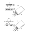
図1は、本発明のリード線用フィルムを説明する図で、(a)リード線用フィルムの層構成を示す断面図、(b)電池リード線、外装体、リード線用フィルムの材質及び位置関係(片側)を説明する図、(c)ヒートシール後のリード線部の模式断面図であり、(d)、(e)および(f)は、別のリード線用フィルムを用いた場合の同様の説明図である。図2は、電池の外装体を形成する積層体の層構成例を示す断面図である。図3は、電池用包装材料とリード線との接着におけるリード線用フィルムの装着方法を説明する斜視図である。図4は、本発明におけるリード線用フィルムのリード線と外装体との間への介在方法を説明する図である。図5は、電池のパウチタイプの外装体を説明する斜視図である。図6は、電池のエンボスタイプの外装体を説明する斜視図である。図7は、エンボスタイプにおける成形を説明する、(a)斜視図、(b)エンボス成形された外装体本体、(c)X2−X2部断面図、(d)Y1部拡大図である。
【0008】
電池のリード線としては、細長の板状または棒状の金属からなり、板状のリード線用としては、厚さが50〜2000μm、 巾 が2.5〜20mm程度であって、その材質としては、 AL、Cu(Niメッキを含む)、Ni、等である。
【0009】
また、電池の外装体のシーラント層(多層シーラント層とする場合には、その最内層)は該シーラント層同士がヒートシール可能な樹脂により形成される。そして、外装体の最内層はリード線に直接ヒートシール可能な樹脂とすることが望ましいが、前述したように、一般的なポリオレフィン例えばポリエチレンやポリプロピレンの単体、またはブレンド物の単層あるいは多層構成からなる樹脂物をシーラント層とし、リード線と該シーラント層とは、リード線用フィルムにより相互にヒートシールして密封する方法がとられている。
【0010】
電池の外装体は、電池本体の性能を長期にわたって維持する性能を有することが求められ、基材層、バリア層、ヒートシール層等を各種のラミネート法によって積層している。特に、電池の外装体(以下、外装体)を構成する積層体のヒートシール層がポリオレフィン系樹脂等からなる場合、電池本体を外装体に収納し、その周縁をシールして密封する際、リード線が存在する部分において、例えば、リード線用フィルムとして酸変性ポリオレフィンを用いる場合、図8(c)及び図8(f)に示すようにヒートシールのための熱と圧力によって前記外装体のシーラント層14’とリード線用フィルム層20’とがともに溶融し、また、加圧によって、絶縁層となっていた外装体のバリア層12’より内側の層、及び、リード線用フィルム層20’が、ともに加圧部の領域の外に押し出されることがある。その結果、外装体のバリア層12’であるアルミニウム箔と金属からなるリード線本体4’とが接触しショートSすることがあった。
【0011】
本発明者らは、前記ショートを防止することについて、鋭意研究の結果、リード線用フィルムの材質及び構成を変更することで、前記課題を解決し得ることを見出し、本発明を完成するに到った。
すなわち、本発明は、図1(b)及び図1(e)に示すように金属であるリード線4と外装体のシーラント層14との間に、次のようなリード線用フィルム20を介在させるものである。
すなわち、該フィルム20を、図1(b)に示すように、ヒートシールによる熱と加圧によりつぶれ難い低流動性ポリプロピレン層(以下、低流動性PP層)22と、つぶれ易い高流動性酸変性ポリプロピレン層(以下、高流動性PPa)21とからなり、リード線4に接する層を高流動性酸変性PPa層21とする
または、図1(e)に示すように、ヒートシールによる熱と加圧により高流動性PP21(2)、低流動性PP22、高流動性PPa21(1)とからなり、リード線に接する層を高流動性PPa21(1)とする。
前記低流動性PP層22は、電池用包装材料の密封に適したヒートシール条件によるヒートシールの熱と圧力とを受けて熔融樹脂となった状態においても低流動性であり、バリア層12とリード線4との間に絶縁膜を存在させる。一方、高流動性PPa層は、金属であるリード線4に対して接着性を示し、かつ熔融時に低粘性となり段差部の密封効果を示す。
本発明における前記低流動性PP22、高流動性PPa21の流動性は、JIS K7210により測定されたメルトインデックス(以下、MIと記載)の値により区別することができる。
本発明における低流動性PP22としてはMIが0.5〜3.0g/10min、また、高流動性PPa21および高流動性PPa(1)、高流動性PP(2)としては、MIが5.0〜30g/10minものが好ましい。
【0012】
本発明のリード線用フィルム20は、例えば、図1(a)に示すように、低流動性PP22と高流動性PPa21とから構成される2層のフィルム、あるいは、図1(d)に示すように、高流動性PP21(2)、低流動性PP22、高流動性PPa21(1)から構成される3層のフィルムである。
【0013】
本発明のリード線用フィルム20における層厚比として、低流動性PP層22と高流動性PPa層21とからなる2層構成の場合、低流動PPの厚さは高流動性PPaの厚さの1.5倍以上とすることが望ましい。また、高流動性PP21(2)、低流動性PP22、高流動性PPa21(1)から構成される3層構成の場合、低流動性PPの厚さは高流動性PPa(1)と高流動性PP(2)との合計の厚みの1.5倍以上とすることが望ましい。低流動性PPの層厚みが、前記2層のリード線用フィルムの場合に高流動性PPa21が、また前記3層リード線用フィルムの場合高流動性PPa21(1)と高流動性PP21(2)との合計の層厚みの1.5倍未満の厚さでは、シール時につぶれてしまい、課題に対する効果が少なくバリア層とリード線との間での短絡の恐れがある。
【0014】
本発明のリード線用フィルムは、共押出し製膜することが望ましい。層の厚さとしては、低流動性PP層が5μm以上、該リード線用フィルム20の総厚は、使用されるリード線の1/3以上有ればよく、たとえば、100μmの厚さのリード線であれば、リード線用フィルム20の総厚は30μm以上あれば良い。
【0015】
本発明のリード線用フィルム20に用いるポリプロピレン系樹脂としては、ホモタイプポリプロピレン、ランダムタイプポリプロピレン、ブロックタイプポリプロピレンを用いることができる。また、酸変性ポリプロピレン系樹脂とは、不飽和カルボン酸をグラフトしたホモタイプポリプロピレン、ランダムタイプポリプロピレン、ブロックタイプポリプロピレンである。
【0016】
本発明の電池リード線用フィルム20を外装体とリード線4との間に介在させて密封シールをした場合に、例えば、低流動性PP22と高流動性PPa21との2層からなるリード線用フィルム20では、図1(c)に示すように、前記密封のための熱、圧力によっても低流動性PP層22は膜状の層としてバリア層12とリード線4との間に残存し、また、高流動性PPa21(2)と低流動性PP22と高流動性PPa21(1)との3層からなるリード線用フィルム20では、図1(f)に示すように、前記密封のための熱、圧力によっても低流動性PP層22は膜状の層として、外装体のバリア層12とリード線4との間に残存し、バリア層12とリード線4とのショートを防止する絶縁層として機能して、前記ショートを回避することができる。
【0017】
電池用包装材料は電池本体を包装する外装体を形成するものであって、その外装体の形式によって、図5に示すようなパウチタイプと、図6(a)、図6(b)または図6(c)に示すようなエンボスタイプとがある。前記パウチタイプには、三方シール、四方シール等及びピロータイプ等の袋形式があるが、図5は、ピロータイプとして例示している。
【0018】
エンボスタイプは、図6(a)に示すように、片面に凹部を形成しても良いし、図6(b)に示すように、両面に凹部を形成して電池本体を収納して周縁の四方をヒートシールして密封しても良い。また、図6(c)に示すような折り部をはさんで両側に凹部形成して、電池を収納して3辺をヒートシールする形式もある。
【0019】
外装体のヒートシール層14として金属に対してヒートシール性を持たない材質とした時には、前述のように、外装体5とリード線4との間にリード線用フィルム20を介在させるがその具体的方法は、例えば、図3(a)及び図3(b)に示すように、電池本体のリード線部密封シール部の上下にリード線用フィルム20をおいて(実際には仮着シールにより固定して)外装体5に挿入しリード線部を挟持した状態でヒートシールすることによって密封する。
【0020】
リード線用フィルム20のリード線4への介在方法として、図3(d)または図3(e)に示すように、リード線4の所定の位置にリード線用フィルム20のフィルムを巻き付けてもよい。
リード線4とリード線用フィルム20は、図4(a)に示すように、リード線4にリード線用フィルム6の酸変性ポリオレフィン21を予め溶着mkさせて用いてもよい。あるいは、図4(b)に示すように、リード線4とリード線用フィルム20とを仮着wkさせた状態で用いてもよい。さらに、図4(c)または図4(d)に示すように、予め外装体10のシーラント層14の面に仮着wkまたは溶着mkさせてもよい。
【0021】
次に、本発明の電池リード線用フィルム20を適用する外装体10の材質について説明する。
前記外装体は、図2(a)に示すように、少なくとも基材層11、接着層16、バリア層12、保護層15、接着樹脂層13、シーラント層14から構成されるものである。あるいは、図2(b)、図2(c)に示すように、少なくとも基材層11、接着層16、保護15(1)、バリア層12、保護層15(2)、接着樹脂層、13、シーラント層14から構成されるものである。
【0022】
本発明のリード線用フィルムに適用する外装体を形成する電池用包装材料を積層する場合の、バリア層12に設けた保護層15とシーラント層14との接着は、例えば、リチウムイオン電池等における電解液と水分との反応により発生するフッ化水素酸などによるデラミネーション防止のために、以下に述べるラミネートおよび接着安定化処理を行うことが望ましい。
【0023】
前記外装体におけるバリア層12とシーラント層14とのラミネートは、図2(a)に示すようにドライラミネート法13dでもよいし、図2(b)に示すように、接着樹脂層13eによりサンドイッチラミネート法、あるいは共押出ラミネート法を用いてもよい。さらに、図2(c)に示すように、酸変性ポリプロピレンのエマルジョン液を塗布乾燥後、更に焼付けた面13hにシーラント層14を熱ラミネート法により積層してもよい。
前記ラミネート法の内、サンドイッチラミネート法、共押出しラミネート法を用いた場合には、ラミネート工程において、バリア層のラミネート面を加熱して積層する方法、または、得られた積層体を後加熱により接着強度の向上を図ることが望ましい。
【0024】
前記基材層11は、電池として用いられる場合、ハードと直接接触する部位であるため、基本的に絶縁性を有する樹脂層がよい。フィルム単体でのピンホールの存在、及び加工時のピンホールの発生等を考慮すると、基材層は6μm以上の厚さが必要であり、好ましい厚さとしては12〜30μmである。
【0025】
外装体における前記基材層11としては、延伸ポリエステルまたはナイロンフィルムからなるが、この時、ポリエステル樹脂としては、ポリエチレンテレフタレート、ポリブチレンテレフタレート、ポリエチレンナフタレート、ポリブチレンナフタレート、共重合ポリエステル、ポリカーボネート等が挙げられる。またナイロンとしては、ポリアミド樹脂、すなわち、ナイロン6、ナイロン6,6、ナイロン6とナイロン6,6との共重合体、ナイロン6,10、ポリメタキシリレンアジパミド(MXD6)等が挙げられる。
【0026】
基材層11は耐ピンホール性及び電池の外装体とした時の絶縁性を向上させるために、積層化することも可能である。
基材層を積層体化する場合、基材層が2層以上の樹脂層を少なくとも一つを含み、各層の厚みが6μm以上、好ましくは、12〜30μmである。基材層を積層化する例としては、次の1)〜8)が挙げられる。
1)延伸ポリエチレンテレフタレート/延伸ナイロン
2)延伸ナイロン/延伸延伸ポリエチレンテレフタレート
また、包装材料の機械適性(包装機械、加工機械の中での搬送の安定性)、表面保護性(耐熱性、耐電解質性)、2次加工とて電池用の外装体をエンボスタイプとする際に、エンボス時の金型と基材層との摩擦抵抗を小さくする目的あるいは電解液が付着した場合に基材層を保護するために、基材層を多層化、基材層表面にフッ素系樹脂層、アクリル系樹脂層、シリコーン系樹脂層、ポリエステル系樹脂層、またはこれらのブレンド物からなる樹脂層等を設けることが好ましい。例えば、
3)フッ素系樹脂/延伸ポリエチレンテレフタレート(フッ素系樹脂は、フィルム状物、または液状コーティング後乾燥で形成)
4)シリコーン系樹脂/延伸ポリエチレンテレフタレート(シリコーン系樹脂は、フィルム状物、または液状コーティング後乾燥で形成)
5)フッ素系樹脂/延伸ポリエチレンテレフタレート/延伸ナイロン
6)シリコーン系樹脂/延伸ポリエチレンテレフタレート/延伸ナイロン 7)アクリル系樹脂/延伸ナイロン(アクリル系樹脂はフィルム状、または液状コーティング後乾燥で硬化)
8)アクリル系樹脂+ポリシロキサングラフト系アクリル樹脂/延伸ナイロン(アクリル系樹脂はフィルム状、または液状コーティング後乾燥で硬化)
また、少なくとも基材層11にエルカ酸アマイド、オレイン酸アマイド、ステアリン酸アマイド、ビスエルカ酸アマイド、ビスオレイン酸アマイド、ビスステアリン酸アマイドに代表される一般的にはポリオレフィン系樹脂に内部添加する滑剤の少なくとも一つを、イソプロピルアルコール、酢酸エチル、トルエン、メチルーエチルーケトン等の溶剤で溶液状とし塗工、塗布することで表面の滑り性が改善され成形性が向上することも判明した。
【0027】
前記バリア層12は、外部から電池の内部に特に水蒸気が浸入することを防止するための層で、バリア層単体のピンホール、及び加工適性(パウチ化、エンボス成形性)を安定化し、かつ耐ピンホールをもたせるために厚さ15μm以上のアルミニウム、ニッケルなどの金属、または、無機化合物、例えば、酸化珪素、アルミナ等を蒸着したフィルムなども挙げられるが、バリア層として好ましくは厚さが20〜80μmのアルミニウムとする。
ピンホールの発生をさらに改善し、電池の外装体のタイプをエンボスタイプとする場合、エンボス成形におけるクラックなどの発生のないものとするために、本発明者らは、バリア層として用いるアルミニウムの材質が、鉄含有量が0.3〜9.0重量%、好ましくは0.7〜2.0重量%とすることによって、鉄を含有していないアルミニウムと比較して、アルミニウムの展延性がよく、積層体として折り曲げによるピンホールの発生が少なくなり、かつ前記エンボスタイプの外装体を成形する時に側壁の形成も容易にできることを見出した。前記鉄含有量が、0.3重量%未満の場合は、ピンホールの発生の防止、エンボス成形性の改善等の効果が認められず、前記アルミニウムの鉄含有量が9.0重量%を超える場合は、アルミニウムとしての柔軟性が阻害され、積層体として製袋性が悪くなる。
【0028】
また、冷間圧延で製造されるアルミニウムは焼きなまし(いわゆる焼鈍処理)条件でその柔軟性・腰の強さ・硬さが変化するが、本発明において用いるアルミニウムは焼きなましをしていない硬質処理品より、多少または完全に焼きなまし処理をした軟質傾向にあるアルミニウムがよい。
前記、アルミニウムの柔軟性・腰の強さ・硬さの度合い、すなわち焼きなましの条件は、加工適性(パウチ化、エンボス成形)に合わせ適宜選定すればよい。例えば、エンボス成形時のしわやピンホールを防止するためには、成形の程度に応じた焼きなましされた軟質アルミニウムを用いることが望ましい。
【0029】
本発明者らは、電池用包装材料のバリア層12であるアルミニウムの表、裏面に化成処理等の保護層を設けることによって、前記包装材料として満足できる積層体とすることができた。例えば、前記化成処理とは、具体的にはリン酸塩、クロム酸塩、フッ化物、トリアジンチオール化合物等の耐酸性皮膜を形成することによってエンボス成形時のアルミニウムと基材層との間のデラミネーション防止と、電池の電解質と水分とによる反応で生成するフッ化水素により、アルミニウム表面の溶解、腐食、特にアルミニウムの表面に存在する酸化アルミが溶解、腐食することを防止し、かつ、アルミニウム表面の接着性(濡れ性)を向上させ、エンボス成形時、ヒートシール時の基材層11とアルミニウム12とのデラミネーション防止、電解質と水分との反応により生成するフッ化水素によるアルミニウム内面側でのデラミネーション防止効果が得られることを確認している。
各種の物質を用いて、アルミニウム面に化成処理を施し、その効果について研究した結果、前記耐酸性皮膜形成物質のなかでも、フェノール樹脂、フッ化クロム(3)化合物、リン酸の3成分から構成されたものを用いるリン酸クロメート処理が良好であった。
または、少なくともフェノール樹脂を含む樹脂成分に、モリブデン、チタン、ジルコン等の金属、または金属塩を含む化成処理剤が良好であった。
【0030】
電池の外装体がパウチタイプの場合には、アルミの化成処理はパウチで用いる場合、ヒートシール層側のみの片側または基材層側とヒートシール層側の両面のどちらでも良い。電池の外装体がエンボスタイプの場合には、アルミニウムの両面に化成処理することによって、エンボス成形の際のアルミニウムと基材層との間のデラミネーションを防止することができる。
【0031】
本発明のリード線用フィルムを適用する場合の外装体のシーラント層は、ホモタイプ、ランダムタイプまたはブロックタイプのプロピレン系樹脂、または、これらのポリプロピレン層を最内層とする多層シーラントとしもよい。
外装体の少なくとも最内層をポリプロピレン樹脂とすることによって、最終製品としての電池としての耐熱性が確保される。
また、ポリプロピレン系樹脂からなるシーラント層14、及び接着樹脂層13にはブテン成分、エチレンとブテンとプロピレンの3成分共重合体からなるターポリマー成分、密度が900kg/m3の低結晶のエチレンとブテンの共重合体、非晶性のエチレンとプロピレンの共重合体、プロピレンーα・オレフィン共重合体成分、ブタジエンゴム等を添加することもできる。
【0032】
本発明の電池用包装材料において、外装体を形成する積層体における前記の各層には、適宜、製膜性、積層化加工、最終製品2次加工(パウチ化、エンボス成形)適性を向上、安定化する目的のために、コロナ処理、ブラスト処理、酸化処理、オゾン処理等の表面活性化処理をしてもよい。
【0033】
【実施例】
本発明の電池リード線用フィルムについて、実施例によりさらに具体的に説明する。
【実施例】
本発明の電池用包装材料ついて、実施例によりさらに具体的に説明する。
実施例比較例ともに共通条件は次の通りである。
(1)外装体
以下の、実施例及び比較例において、パウチタイプの外装体としては、巾30mm巾、長さ50mm(いずれも内寸)とし、また、エンボスタイプの外装体の場合は、いずれも片面エンボスタイプとし、成形型の凹部(キャビティ)の形状を30mm×50mm,深さ3.5mmとしてプレス成形して成形性の評価をした。
(2)シーラント層は、いずれも、ランダムポリプロピレン樹脂(MI=7g/10min、融点147℃)からなる30μmの厚さの層とした。
(3)化成処理
外装体のバリア層に化成処理を施す場合は、実施例、比較例ともに、処理液として、フェノール樹脂、フッ化クロム(3)化合物、リン酸からなる水溶液を、ロールコート法により、塗布し、皮膜温度が180℃以上となる条件において焼き付けた。クロムの塗布量は、2mg/m2(乾燥重量)とした。
(4)リード線
実施例、比較例ともに、リード線はいずれも100μmの厚さ、4mm巾、長さ25mmのものとした。
リード線用フィルムは、いずれも100μmの厚さとして、電池本体のリード線の所定の位置に巻き付けた後、電池本体をそれぞれの外装体に挿入した。
(5)ヒートシール条件
ヒートシール条件としては、190℃、2.0MPa、5secとした。
[実施例1]
アルミニウム20μmの片面に化成処理を施し、化成処理していない面に延伸ポリエステルフィルム(厚さ12μm)をドライラミネート法により貼り合わせ、次に、化成処理したアルミニウムの他の面を、接着樹脂層となる酸変性ポリプロピレン(以下、PPa)の軟化点以上の温度に加熱して、PPaを押出してシーラント層となるランダムタイプポリプロピレンフィルムからなるシーラント層をサンドイッチラミネート法により貼り合わせて得られた積層体を用いて外装体としてピロータイプのパウチを形成した。
リード線用フィルムの構成は、次の通りである。
低流動性PP(MI0.5g/10min、融点160℃)<60>/高流動性PPa(MI28g/10min、融点160℃)<40>の2層共押出しフィルムとした。<>内数値は、共押出し多層の層厚み比を示し、以下の実施例、比較例も同じである。
電池本体を、前記外装体中に挿入し、ヒートシールにより密封し検体実施例1とした。
[実施例2]
アルミニウム40μmの両面に化成処理を施し、化成処理した一方の面に延伸ナイロンフィルム(厚さ25μm)をドライラミネート法により貼り合わせ、次に、化成処理したアルミニウムの他の面にドライラミネート法によりランダムタイプポリプロピレンからなるシーラント層を貼り合わせた。得られた積層体を用いてエンボス成形によりトレイを形成した。成形しない積層体を蓋体として、エンボスタイプの外装体を得た。
リード線用フィルムの構成は、次の通りである。
高流動性PP(MI10g/10min、融点147℃)<5>/低流動性PP(MI1.0g/10min、融点160℃)<90>/高流動性PPa(MI10g/10min、融点147℃)<5>の3層共押出しフィルムとした。
電池本体を、前記外装体中に挿入し、ヒートシールにより密封し検体実施例2とした。
[実施例3]
アルミニウム40μmの両面に化成処理を施し、化成処理した一方の面に延伸ナイロンフィルム(厚さ25μm)をドライラミネート法により貼り合わせ、次に、化成処理したアルミニウムの他の面に、酸変性ポリプロピレンのエマルジョン液を塗布乾燥し、更に、180℃の温度で焼付けた後、該焼付層の面に熱ラミネート法によりシーラント層を貼り合わせた。得られた積層体を用いてエンボス成形によりトレイを形成した。成形しない積層体を蓋体として、エンボスタイプの外装体を得た。
リード線用フィルムの構成は、次の通りである。
低流動性PP(MI3.0、融点147℃)<95>/高流動性PPa(MI7.0g/10min、融点147℃)<5>の2層共押出しフィルムとした。
電池本体を、前記外装体中に挿入し、ヒートシールにより密封し検体実施例3とした。
[実施例4]
アルミニウム40μmの両面に化成処理を施し、化成処理した一方の面に延伸ナイロンフィルム(厚さ25μm)をドライラミネート法により貼り合わせ、次に、化成処理したアルミニウムの他の面に、酸変性ポリプロピレンを接着樹脂としてサンドイッチラミネート法によりランダムポリプロピレンフィルムからなるシーラント層を貼り合わせた。得られた積層体を、酸変性ポリプロピレンの軟化点以上の温度に加熱した後、この積層体を用いてエンボス成形によりトレイを形成した。成形しない積層体を蓋体として、エンボスタイプの外装体を得た。
リード線用フィルムの構成は、次の通りである。
高流動性PP(MI8g/10min、融点147℃)<10>/低流動性PP(MI1.5g/10min、融点160℃)<80>/高流動性PPa(MI8g/10min、融点165℃)<10>の3層共押出しフィルムとした。
電池本体を、前記外装体中に挿入し、ヒートシールにより密封し検体実施例4とした。
[実施例5]
アルミニウム40μmの両面に化成処理を施し、化成処理した一方の面に延伸ナイロンフィルム(厚さ25μm)をドライラミネート法により貼り合わせ、次に、化成処理したアルミニウムの他の面に、酸変性ポリプロピレンを接着樹脂として共押出ラミネート法によりシーラント層となるランダムポリプロピレン樹脂とを共押出しして貼り合わせた。得られた積層体を、酸変性ポリプロピレンの軟化点以上の温度に加熱した後、この積層体を用いてエンボス成形によりトレイを形成した。成形しない積層体を蓋体として、エンボスタイプの外装体を得た。
リード線用フィルムの構成は、次の通りである。
高流動性PP(MI20g/10min、融点160℃)<5>/低流動性PP(MI3g/10min、融点160℃)<75>/高流動性PPa(MI8g/10min、融点147℃)<20>の3層共押出しフィルムとした。
電池本体を、前記外装体中に挿入し、ヒートシールにより密封し検体実施例5とした。
【0034】
[比較例1]
アルミニウム40μmの両面に化成処理を施し、化成処理した一方の面に延伸ナイロンフィルム(厚さ25μm)をドライラミネート法により貼り合わせ、次に、化成処理したアルミニウムの他の面に、酸変性ポリプロピレンのエマルジョン液を塗布乾燥し、更に、180℃の温度で焼付けた後、該焼付層の面に熱ラミネート法によりシーラント層を貼り合わせた。得られた積層体を用いてエンボス成形によりトレイを形成した。成形しない積層体を蓋体として、エンボスタイプの外装体を得た。
リード線用フィルムの構成は、次の通りである。
MI=20g/10min、融点147℃の酸変性PPフィルムとした。
電池本体を、前記外装体中に挿入し、ヒートシールにより密封し検体比較例1とした。
[比較例2]
アルミニウム40μmの両面に化成処理を施し、化成処理した一方の面に延伸ナイロンフィルム(厚さ25μm)をドライラミネート法により貼り合わせ、次に、化成処理したアルミニウムの他の面に、酸変性ポリプロピレンを接着樹脂としてサンドイッチラミネート法によりランダムポリプロピレンフィルムからなるシーラント層を貼り合わせた。得られた積層体を、酸変性ポリプロピレンの軟化点以上の温度に加熱した後、この積層体を用いてエンボス成形によりトレイを形成した。成形しない積層体を蓋体として、エンボスタイプの外装体を得た。
リード線用フィルムの構成は、次の通りである。
低流動性PP(MI0.5g/10min、融点160℃)<10>/高流動性PPa(MI20g/10min、融点165℃)<90>の2層共押出しフィルムとした。
電池本体を、前記外装体中に挿入し、ヒートシールにより密封し検体比較例2とした。
[比較例3]
アルミニウム40μmには化成処理を施さないで、一方の面に延伸ナイロンフィルム(厚さ25μm)をドライラミネート法により貼り合わせ、次に、他の面に、酸変性ポリプロピレンを接着樹脂としてサンドイッチラミネート法によりランダムポリプロピレンフィルムからなるシーラント層を貼り合わせた。得られた積層体を、酸変性ポリプロピレンの軟化点以上の温度に加熱した後、この積層体を用いてエンボス成形によりトレイを形成した。成形しない積層体を蓋体として、エンボスタイプの外装体を得た。
リード線用フィルムの構成は、次の通りである。
高流動性PP(MI8g/10min、融点147℃)<10>/低流動性PP(MI1.5g/10min、融点160℃)<80>/高流動性PPa(MI8g/10min、融点160℃)<10>の3層共押出しフィルムとした。
電池本体を、前記外装体中に挿入し、ヒートシールにより密封し検体実施例3とした。
【0035】
<評価方法>
(1)リード線と外装体のバリア層との短絡の有無
リード線部と外装体とのショート状態とを、リード線部のヒートシール部を断裁し、断面写真により確認し、リード線と外装体のバリア層とのショートのおそれのあるものについては、テスターによって接触を確認し、断面写真によって、リード線と外装体のバリア層との間に皮膜が見られないものをショート寸前とし、その内でテスターによりショートが確認された検体をショート数とした。
2)もれとデラミネーションの確認
ヒートシール品を80℃、24時間保存し、リード線部からの内容物のもれと、内容物側の積層体のデラミネーション(以下デラミ)を確認した。
内容物:電解液1M LiPF6となるようにしたエチレンカーボネート、ジエチルカーボネート、ジメチルカーボネート(1:1:1)の混合液、3g。
【0036】
<結果>
実施例1〜実施例5はいずれも、リード線部でのショート、デラミおよび漏れは皆無であった。
比較例1においては、デラミはみとめられなかったが、500検体中15検体にショートが認められた。比較例2においては、デラミはみとめられなかったが、500検体中20検体にショートが認められた。比較例3においては、ショートおよび漏れは認められなかったが、500検体中150検体にデラミが認められた。また、比較例1から3においては漏れは認められなかった。
【0037】
【発明の効果】
本発明の電池用包装材料から形成された外装体のパウチまたはエンボス成形部に電池本体を収納しその周縁をヒートシールして密封する際、電池のリード線と外装体との間介在させるリード線用フィルムを、少なくともヒートシールによる熱と加圧によりつぶれ難い低流動性ポリプロピレン層とつぶれ易い高流動性の酸変性ポリプロピレン層とを含む多層フィルムであり、リード線側を高流動性の酸変性ポリプロピレン層とすることによって、電池の密封シールの際に、外装体のバリア層とリード線とが接触(ショート)することがなくなった。
また、外装体のアルミニウムの両面に施した化成処理等の保護層によって、エンボス成形時、及びヒートシール時の基材層とアルミニウムとの間でのデラミネーションの発生を防止することができ、また、ヒートシール層をサンドイッチラミネート法または共押出ラミネート法により形成した場合に、積層体の形成時の加熱、または積層体形成後の加熱によって、電池の電解質と水分との反応により発生するフッ化水素によるアルミニウム面の腐食を防止できることにより、アルミニウムとの内容物側の層とのデラミネーションをも防止できる外装体とすることができた。
【図面の簡単な説明】
【図1】本発明のリード線用フィルムを説明する図で、(a)リード線用フィルムの層構成を示す断面図、(b)電池リード線、外装体、リード線用フィルムの材質及び位置関係(片側)を説明する図、(c)ヒートシール後のリード線部の模式断面図であり、(d)、(e)および(f)は、別のリード線用フィルムを用いた場合の同様の説明図である。
【図2】電池の外装体を形成する積層体の層構成例を示す断面図である。
【図3】電池用包装材料とリード線との接着におけるリード線用フィルムの装着方法を説明する斜視図である。
【図4】本発明におけるリード線用フィルムのリード線と外装体との間への介在方法を説明する図である。
【図5】電池のパウチタイプの外装体を説明する斜視図である。
【図6】電池のエンボスタイプの外装体を説明する斜視図である。
【図7】エンボスタイプにおける成形を説明する、(a)斜視図、(b)エンボス成形された外装体本体、(c)X2−X2部断面図、(d)Y1部拡大図である。
【図8】従来のリード線用フィルムを用いてバリア層とリード線とがショートした状態を示す断面図である。
【符号の説明】
S リード線とバリア層とのショート部
H ヒートシール熱板
wk 仮着
mk 溶着
1 電池
2 電池本体
3 セル(蓄電部)
4 リード線(電極)
5 外装体
7 凹部
8 側壁部
9 シール部
10 積層体(電池用包装材料)
11 基材層
12 アルミニウム(バリア層)
13 バリア層とシーラント層との接着層(接着樹脂層)
13d ドライラミネート層
13e 酸変性ポリプロピレンの押出層
13h 酸変性ポリプロピレンの塗布焼付け層
14 ヒートシール層
15 保護層
16 基材層とバリア層間の接着層
20 リード線用フィルムの積層体
21 高流動性PPa層
22 低流動性PP層
30 プレス成形部
31 オス型
32 メス型
33 キャビティ[0001]
BACKGROUND OF THE INVENTION
A battery lead film and a battery packaging material using the same according to the present invention include a battery having a liquid or solid organic electrolyte (polymer polymer electrolyte) having moisture resistance and content resistance, or a fuel cell, a capacitor, A packaging material used for capacitors and the like, and an outer body for packaging a battery body, a lead wire film interposed between the lead wire portion and the outer body of the battery, a lead wire using the film, a packaging material for the battery, The present invention relates to a battery having a packaging material as an exterior body.
[0002]
[Prior art]
The battery in the present invention refers to a substance including an element that converts chemical energy into electric energy, for example, a lithium ion battery, a lithium polymer battery, a fuel cell, or a dielectric such as a liquid, a solid ceramic, or an organic substance. Including electrolytic capacitors such as liquid capacitors, solid capacitors, double layer capacitors.
Applications of the battery include personal computers, portable terminal devices (cell phones, PDAs, etc.), video cameras, electric vehicles, energy storage batteries, robots, satellites, and the like.
As the battery exterior body, a metal can obtained by pressing a metal into a cylindrical or rectangular parallelepiped container, or a laminate made of a composite film obtained by laminating a plastic film, a metal foil or the like into a bag shape. (Hereinafter referred to as an exterior body) was used.
There were the following problems as a battery outer package. In a metal can, since the outer wall of the container is rigid, the shape of the battery itself is determined. Therefore, since the hardware side is designed to match the battery, the size of the hardware using the battery is determined by the battery, and the degree of freedom in shape is reduced.
Therefore, it exists in the tendency to use the said bag-shaped exterior body. The material structure of the exterior body includes at least a base material layer, a barrier layer, a sealant layer, and an adhesive layer that bonds the respective layers in view of necessary physical properties, workability, economy, and the like as a battery. May be provided.
A pouch is formed from the laminated body of the above-described configuration of the battery, or at least one side is press-molded to form a battery storage portion to store the battery body, and the pouch type or embossed type (covering the cover) In the above, a necessary part of each peripheral edge is sealed by heat sealing to obtain a battery.
The sealant layer (in the case of a multilayer sealant layer, the innermost layer, the same shall apply hereinafter) is required to have heat sealability with respect to the lead wire (metal) as well as heat sealability between the sealant layers, and metal adhesion For example, the adhesiveness with the lead wire portion is ensured by using an acid-modified polyolefin resin as the innermost layer.
[0003]
However, when the acid-modified polyolefin resin is laminated as the innermost layer of the outer package, the processability is inferior to that of a general polyolefin resin, and the cost is high. A method of adopting a general polyolefin resin layer and a lead wire film that can be thermally bonded to both the sealant layer and the lead wire in the lead wire portion has been adopted.
Specifically, as shown in FIG. 8A, between the
As the lead film, a film made of the unsaturated carboxylic graft polyolefin, metal-crosslinked polyethylene, a copolymer of ethylene or propylene and acrylic acid or methacrylic acid can be used.
[0004]
[Problems to be solved by the invention]
However, when the sealant layer of the laminate constituting the battery outer body (hereinafter referred to as the outer body) is made of a polyolefin-based resin, the battery body is housed in the outer body and the periphery thereof is sealed and sealed. In the case where the
An object of the present invention is to provide a barrier for an exterior body by heat and pressure of the heat seal when the battery body is inserted into an exterior body having a polypropylene resin as a sealant layer and the periphery thereof is heat-sealed and sealed. An object of the present invention is to provide a battery lead film and a battery packaging material using the same, which can be stably sealed without causing a short circuit between the layer and the lead.
[0005]
[Means for Solving the Problems]
The above problems can be solved by the following present invention. That is, the invention described in
[0006]
DETAILED DESCRIPTION OF THE INVENTION
The present invention includes a barrier layer made of a metal foil, and sandwiches a lead wire body made of an elongated plate or a rod-like metal in a peripheral seal portion of an outer package made of a laminate having heat sealability on the inner surface, When sealing the peripheral edge of the outer package, the structure of the film interposed between the laminate and the lead wire main body is at least a low-fluidity polypropylene layer that is not easily crushed by heat and pressure by heat sealing. It is a multilayer film including a fluid acid-modified polypropylene layer, and the lead wire side is a highly fluid acid-modified polypropylene layer. Hereinafter, the present invention will be described in more detail with reference to the drawings and the like, but a battery will be described as a specific example.
[0007]
1A and 1B are diagrams for explaining a lead wire film of the present invention, in which FIG. 1A is a cross-sectional view showing the layer structure of the lead wire film, and FIG. The figure explaining a relationship (one side), (c) It is a schematic cross section of the lead wire part after heat sealing, (d), (e), and (f) are the cases at the time of using another lead wire film It is the same explanatory drawing. FIG. 2 is a cross-sectional view showing an example of a layer structure of a laminate that forms an outer package of a battery. FIG. 3 is a perspective view for explaining a method for attaching a lead wire film in bonding the battery packaging material and the lead wire. FIG. 4 is a diagram for explaining a method of interposing the lead wire film between the lead wire and the exterior body in the present invention. FIG. 5 is a perspective view for explaining a pouch-type exterior body of a battery. FIG. 6 is a perspective view for explaining an embossed type exterior body of a battery. 7A and 7B illustrate molding in an embossed type, (a) perspective view, (b) embossed exterior body, (c) X 2 -X 2 Partial sectional view, (d) Y 1 FIG.
[0008]
The lead wire of the battery is made of an elongated plate-like or rod-like metal, and for the plate-like lead wire, the thickness is about 50 to 2000 μm, and the width is about 2.5 to 20 mm. AL, Cu (including Ni plating), Ni, and the like.
[0009]
Moreover, the sealant layer (the innermost layer in the case of a multilayer sealant layer) of the battery outer package is formed of a resin that can be heat-sealed between the sealant layers. The innermost layer of the outer package is preferably a resin that can be heat-sealed directly to the lead wire. However, as described above, a single polyolefin or a single layer or a multilayer structure of a general polyolefin, such as polyethylene or polypropylene, is used. A resin material is used as a sealant layer, and the lead wire and the sealant layer are sealed by heat sealing with a lead wire film.
[0010]
The battery exterior body is required to have the performance of maintaining the performance of the battery body for a long period of time, and a base material layer, a barrier layer, a heat seal layer, and the like are laminated by various laminating methods. In particular, when the heat seal layer of the laminate constituting the battery outer body (hereinafter referred to as the outer body) is made of a polyolefin-based resin or the like, when the battery body is housed in the outer body and the periphery is sealed and sealed, the lead For example, when acid-modified polyolefin is used as a lead wire film in the portion where the wire exists, the sealant of the outer package is applied by heat and pressure for heat sealing as shown in FIGS. 8 (c) and 8 (f). The
[0011]
As a result of intensive research on the prevention of the short circuit, the present inventors have found that the problem can be solved by changing the material and configuration of the lead wire film, and the present invention has been completed. It was.
That is, according to the present invention, as shown in FIGS. 1B and 1E, the following
That is, as shown in FIG. 1B, the
Alternatively, as shown in FIG. 1 (e), a layer that is made of high fluidity PP21 (2), low fluidity PP22, and high fluidity PPa21 (1) by heat and pressure by heat sealing, and that is in contact with the lead wire. High fluidity PPa21 (1).
The low-
The fluidity of the low fluidity PP22 and the high fluidity PPa21 in the present invention can be distinguished by the melt index value (hereinafter referred to as MI) measured by JIS K7210.
In the present invention, the low flow PP22 has an MI of 0.5 to 3.0 g / 10 min, and the high flow PPa21, the high flow PPa (1), and the high flow PP (2) have an MI of 5. The thing of 0-30 g / 10min is preferable.
[0012]
The
[0013]
As the layer thickness ratio in the
[0014]
The lead wire film of the present invention is preferably co-extruded to form a film. The layer thickness is 5 μm or more for the low-fluidity PP layer, and the total thickness of the
[0015]
As the polypropylene resin used for the
[0016]
When the battery
[0017]
The battery packaging material forms an exterior body for packaging the battery body. Depending on the form of the exterior body, the pouch type as shown in FIG. 5 and FIGS. 6 (a), 6 (b) or FIG. There is an embossing type as shown in 6 (c). The pouch type includes three-side seals, four-side seals, and pillow types such as a pillow type. FIG. 5 shows an example of the pillow type.
[0018]
As shown in FIG. 6 (a), the embossed type may be formed with a recess on one side, and as shown in FIG. 6 (b), a recess is formed on both sides to accommodate the battery body and Four sides may be heat sealed. In addition, there is a type in which a concave portion is formed on both sides with a folding portion as shown in FIG.
[0019]
When the
[0020]
As a method for interposing the
As shown in FIG. 4A, the
[0021]
Next, the material of the
As shown in FIG. 2A, the exterior body is composed of at least a
[0022]
The adhesion between the
[0023]
The laminate of the
Among the laminating methods, when the sandwich laminating method or the coextrusion laminating method is used, in the laminating process, the laminating surface of the barrier layer is heated and laminated, or the obtained laminated body is bonded by post-heating. It is desirable to improve the strength.
[0024]
When the
[0025]
The
[0026]
The
When the base material layer is laminated, the base material layer includes at least one resin layer of two or more layers, and the thickness of each layer is 6 μm or more, preferably 12 to 30 μm. Examples of laminating the base material layer include the following 1) to 8).
1) Stretched polyethylene terephthalate / stretched nylon
2) Stretched nylon / stretched stretched polyethylene terephthalate
In addition, the mechanical suitability of packaging materials (stability of conveyance in packaging machines and processing machines), surface protection (heat resistance, electrolyte resistance), secondary processing, and battery exterior bodies are embossed. In order to reduce the frictional resistance between the mold and the base material layer during embossing or to protect the base material layer when an electrolytic solution adheres, the base material layer is multilayered and fluorine is applied to the surface of the base material layer. It is preferable to provide a resin layer made of a resin-based resin layer, an acrylic resin layer, a silicone-based resin layer, a polyester-based resin layer, or a blend thereof. For example,
3) Fluorine resin / stretched polyethylene terephthalate (Fluorine resin is a film or formed by drying after liquid coating)
4) Silicone resin / stretched polyethylene terephthalate (silicone resin is a film or formed by drying after liquid coating)
5) Fluorine resin / stretched polyethylene terephthalate / stretched nylon
6) Silicone resin / stretched polyethylene terephthalate / stretched nylon 7) Acrylic resin / stretched nylon (acrylic resin is film-like or cured after drying by liquid coating)
8) Acrylic resin + polysiloxane graft acrylic resin / stretched nylon (acrylic resin is film-like or cured by drying after liquid coating)
In addition, a lubricant that is internally added to a polyolefin-based resin, typically represented by erucic acid amide, oleic acid amide, stearic acid amide, biserucic acid amide, bisoleic acid amide, and bisstearic acid amide at least in the
[0027]
The
In order to further improve the generation of pinholes and to make the battery exterior body type an embossed type, in order to prevent the occurrence of cracks in the embossing molding, the present inventors have made a material for aluminum used as a barrier layer. However, when the iron content is 0.3 to 9.0% by weight, preferably 0.7 to 2.0% by weight, the ductility of aluminum is better than that of aluminum not containing iron. The present inventors have found that the generation of pinholes due to bending is reduced as a laminate, and the side wall can be easily formed when the embossed type exterior body is formed. When the iron content is less than 0.3% by weight, effects such as prevention of pinholes and improvement of embossing formability are not observed, and the iron content of the aluminum exceeds 9.0% by weight. In such a case, the flexibility as aluminum is hindered, and the bag-making property is deteriorated as a laminate.
[0028]
In addition, aluminum produced by cold rolling changes its flexibility, waist strength and hardness under annealing (so-called annealing treatment) conditions, but the aluminum used in the present invention is harder than the non-annealed hard-treated product. Aluminum which tends to be soft with some or complete annealing is preferred.
The degree of flexibility, waist strength, and hardness of aluminum, that is, the conditions for annealing, may be appropriately selected in accordance with processability (pouching, embossing). For example, in order to prevent wrinkles and pinholes during embossing, it is desirable to use soft aluminum annealed according to the degree of forming.
[0029]
The present inventors have been able to obtain a laminate that is satisfactory as the packaging material by providing protective layers such as chemical conversion treatment on the front and back surfaces of aluminum, which is the
As a result of conducting chemical conversion treatment on the aluminum surface using various substances and studying the effect, it is composed of three components of phenolic resin, chromium fluoride (3) compound and phosphoric acid among the acid-resistant film-forming substances. The treatment with phosphoric acid chromate using the prepared product was good.
Or the chemical conversion treatment agent which contains metals, such as molybdenum, titanium, a zircon, or a metal salt in the resin component containing a phenol resin at least was favorable.
[0030]
When the battery outer package is of a pouch type, the chemical conversion treatment of aluminum may be performed on one side only on the heat seal layer side or on both sides of the base material layer side and the heat seal layer side when used in the pouch. When the battery outer body is an embossed type, delamination between the aluminum and the base material layer during embossing can be prevented by subjecting both surfaces of the aluminum to chemical conversion treatment.
[0031]
The sealant layer of the outer package in the case of applying the lead wire film of the present invention may be a homo-type, random-type or block-type propylene resin, or a multilayer sealant having these polypropylene layers as the innermost layer.
By using at least the innermost layer of the exterior body as a polypropylene resin, heat resistance as a battery as a final product is secured.
The
[0032]
In the battery packaging material of the present invention, for each of the layers in the laminate forming the outer package, film forming properties, lamination processing, final product secondary processing (pouching, embossing) suitability are improved and stabilized as appropriate. For the purpose of conversion, surface activation treatment such as corona treatment, blast treatment, oxidation treatment, and ozone treatment may be performed.
[0033]
【Example】
The battery lead wire film of the present invention will be described more specifically with reference to examples.
【Example】
The battery packaging material of the present invention will be described more specifically with reference to examples.
Common conditions are as follows in both of the comparative examples.
(1) Exterior body
In the following examples and comparative examples, the pouch-type exterior body is 30 mm wide and 50 mm long (both inner dimensions), and in the case of an embossed-type exterior body, both are single-sided embossed types. The shape of the concave portion (cavity) of the mold was 30 mm × 50 mm and the depth was 3.5 mm, and the moldability was evaluated by press molding.
(2) Each of the sealant layers was a layer having a thickness of 30 μm made of random polypropylene resin (MI = 7 g / 10 min, melting point 147 ° C.).
(3) Chemical conversion treatment
When chemical conversion treatment is performed on the barrier layer of the outer package, both the examples and the comparative examples are coated with an aqueous solution composed of a phenol resin, a chromium fluoride (3) compound and phosphoric acid by a roll coating method. Baking was performed under conditions where the film temperature was 180 ° C. or higher. The application amount of chromium is 2mg / m 2 (Dry weight).
(4) Lead wire
In both the examples and comparative examples, the lead wires were 100 μm thick, 4 mm wide, and 25 mm long.
Each of the lead wire films had a thickness of 100 μm and was wound around a predetermined position of the lead wire of the battery main body, and then the battery main body was inserted into each exterior body.
(5) Heat sealing conditions
The heat seal conditions were 190 ° C., 2.0 MPa, and 5 sec.
[Example 1]
One side of
The structure of the lead wire film is as follows.
A two-layer coextruded film of low flow PP (MI 0.5 g / 10 min, melting point 160 ° C.) <60> / high flow PPa (MI 28 g / 10 min, melting point 160 ° C.) <40>. The numerical value in <> indicates the layer thickness ratio of the co-extruded multilayer, and the following examples and comparative examples are the same.
The battery main body was inserted into the outer package and sealed by heat sealing to give Sample Example 1.
[Example 2]
Chemical conversion treatment was applied to both sides of 40 μm aluminum, and a stretched nylon film (thickness 25 μm) was bonded to one side of the chemical conversion treatment by a dry laminating method. A sealant layer made of type polypropylene was bonded. A tray was formed by embossing using the obtained laminate. An embossed-type exterior body was obtained using the unmolded laminate as a lid.
The structure of the lead wire film is as follows.
High fluidity PP (MI 10 g / 10 min, melting point 147 ° C.) <5> / Low fluidity PP (MI 1.0 g / 10 min, melting point 160 ° C.) <90> / High fluidity PPa (MI 10 g / 10 min, melting point 147 ° C.) <5> three-layer coextruded film.
The battery main body was inserted into the outer package and sealed by heat sealing, and
[Example 3]
Chemical conversion treatment was applied to both sides of aluminum 40 μm, and a stretched nylon film (thickness 25 μm) was bonded to one side of the chemical conversion treatment by a dry laminating method, and then the other surface of the chemical conversion treatment aluminum was coated with acid-modified polypropylene. After the emulsion liquid was applied and dried, and further baked at a temperature of 180 ° C., a sealant layer was bonded to the surface of the baked layer by a heat laminating method. A tray was formed by embossing using the obtained laminate. An embossed-type exterior body was obtained using the unmolded laminate as a lid.
The structure of the lead wire film is as follows.
A two-layer coextruded film of low flow PP (MI 3.0, melting point 147 ° C.) <95> / high flow PPa (MI 7.0 g / 10 min, melting point 147 ° C.) <5> was obtained.
The battery main body was inserted into the outer package and sealed by heat sealing to give Sample Example 3.
[Example 4]
Chemical conversion treatment was performed on both sides of 40 μm aluminum, and a stretched nylon film (thickness 25 μm) was bonded to one side of the chemical conversion treatment by a dry laminating method. Next, acid-modified polypropylene was applied to the other side of the chemical conversion treatment aluminum. A sealant layer made of a random polypropylene film was bonded as an adhesive resin by a sandwich lamination method. The obtained laminate was heated to a temperature equal to or higher than the softening point of the acid-modified polypropylene, and a tray was formed by embossing using this laminate. An embossed-type exterior body was obtained using the unmolded laminate as a lid.
The structure of the lead wire film is as follows.
High fluidity PP (MI 8 g / 10 min, melting point 147 ° C.) <10> / Low fluidity PP (MI 1.5 g / 10 min, melting point 160 ° C.) <80> / High fluidity PPa (MI 8 g / 10 min, melting point 165 ° C.) <10> three-layer coextruded film.
A battery main body was inserted into the outer package and sealed by heat sealing to give a sample of Example 4.
[Example 5]
Chemical conversion treatment was performed on both sides of 40 μm aluminum, and a stretched nylon film (thickness 25 μm) was bonded to one side of the chemical conversion treatment by a dry laminating method. Next, acid-modified polypropylene was applied to the other side of the chemical conversion treatment aluminum. Random polypropylene resin which becomes a sealant layer was coextruded and bonded as an adhesive resin by a coextrusion laminating method. The obtained laminate was heated to a temperature equal to or higher than the softening point of the acid-modified polypropylene, and a tray was formed by embossing using this laminate. An embossed-type exterior body was obtained using the unmolded laminate as a lid.
The structure of the lead wire film is as follows.
High flowability PP (MI 20 g / 10 min, melting point 160 ° C.) <5> / Low flowability PP (MI 3 g / 10 min, melting point 160 ° C.) <75> / High flowability PPa (MI 8 g / 10 min, melting point 147 ° C.) <20> A three-layer coextruded film.
The battery main body was inserted into the outer package and sealed by heat sealing to give Sample Example 5.
[0034]
[Comparative Example 1]
Both surfaces of aluminum 40 μm were subjected to chemical conversion treatment, and a stretched nylon film (thickness 25 μm) was bonded to one side of the chemical conversion treatment by a dry laminating method, and then the other surface of the chemical conversion treatment aluminum was coated with acid-modified polypropylene. After the emulsion liquid was applied and dried, and further baked at a temperature of 180 ° C., a sealant layer was bonded to the surface of the baked layer by a heat laminating method. A tray was formed by embossing using the obtained laminate. An embossed-type exterior body was obtained using the unmolded laminate as a lid.
The structure of the lead wire film is as follows.
An acid-modified PP film having MI = 20 g / 10 min and a melting point of 147 ° C. was obtained.
A battery main body was inserted into the outer package and sealed by heat sealing to make a specimen comparative example 1.
[Comparative Example 2]
Chemical conversion treatment was performed on both sides of 40 μm aluminum, and a stretched nylon film (thickness 25 μm) was bonded to one side of the chemical conversion treatment by a dry laminating method. Next, acid-modified polypropylene was applied to the other side of the chemical conversion treatment aluminum. A sealant layer made of a random polypropylene film was bonded as an adhesive resin by a sandwich lamination method. The obtained laminate was heated to a temperature equal to or higher than the softening point of the acid-modified polypropylene, and a tray was formed by embossing using this laminate. An embossed-type exterior body was obtained using the unmolded laminate as a lid.
The structure of the lead wire film is as follows.
A two-layer coextruded film of low flow PP (MI 0.5 g / 10 min, melting point 160 ° C.) <10> / high flow PPa (MI 20 g / 10 min, melting point 165 ° C.) <90>.
A battery main body was inserted into the outer package and sealed by heat sealing to provide a specimen comparative example 2.
[Comparative Example 3]
Aluminum 40 μm is not subjected to chemical conversion treatment, and a stretched nylon film (thickness 25 μm) is bonded to one surface by a dry lamination method, and then the other surface is subjected to a sandwich lamination method using acid-modified polypropylene as an adhesive resin. A sealant layer made of a random polypropylene film was bonded. The obtained laminate was heated to a temperature equal to or higher than the softening point of the acid-modified polypropylene, and a tray was formed by embossing using this laminate. An embossed-type exterior body was obtained using the unmolded laminate as a lid.
The structure of the lead wire film is as follows.
High flowability PP (MI 8 g / 10 min, melting point 147 ° C.) <10> / Low flowability PP (MI 1.5 g / 10 min, melting point 160 ° C.) <80> / High flowability PPa (MI 8 g / 10 min, melting point 160 ° C.) <10> three-layer coextruded film.
The battery main body was inserted into the outer package and sealed by heat sealing to give Sample Example 3.
[0035]
<Evaluation method>
(1) Presence or absence of short circuit between the lead wire and the barrier layer of the outer package
Test the lead wire part and the outer body short-circuited by cutting the heat seal part of the lead wire part and checking the cross-sectional photograph. In the cross-sectional photograph, no contact was observed between the lead wire and the barrier layer of the outer package, and the specimen that was confirmed to be short-circuited by the tester was defined as the number of shorts.
2) Check for leaks and delamination
The heat-sealed product was stored at 80 ° C. for 24 hours, and leakage of contents from the lead wire part and delamination (hereinafter referred to as delamination) of the laminate on the contents side were confirmed.
Contents: Electrolyte 1M LiPF 6 3 g of a mixed solution of ethylene carbonate, diethyl carbonate and dimethyl carbonate (1: 1: 1).
[0036]
<Result>
In all of Examples 1 to 5, there was no short-circuit, delamination, and leakage at the lead wire portion.
In Comparative Example 1, no delamination was observed, but a short circuit was observed in 15 of 500 samples. In Comparative Example 2, delamination was not observed, but a short circuit was observed in 20 of 500 samples. In Comparative Example 3, no short circuit or leakage was observed, but delamination was observed in 150 samples out of 500 samples. In Comparative Examples 1 to 3, no leakage was observed.
[0037]
【The invention's effect】
A lead wire interposed between a battery lead wire and an exterior body when the battery body is housed in a pouch or an emboss molding part of the exterior body formed from the battery packaging material of the present invention and the periphery thereof is heat sealed. Film is a multilayer film including at least a low-flowability polypropylene layer that is not easily crushed by heat and pressure by heat sealing and a high-fluidity acid-modified polypropylene layer that is easily crushed, and the lead wire side is a high-fluidity acid-modified polypropylene. By using the layer, the barrier layer of the outer package and the lead wire do not contact (short-circuit) when the battery is hermetically sealed.
In addition, the protective layer such as chemical conversion treatment applied to both sides of the aluminum of the exterior body can prevent the occurrence of delamination between the base material layer and aluminum during embossing and heat sealing, When the heat seal layer is formed by sandwich lamination method or coextrusion lamination method, hydrogen fluoride is generated by the reaction between the electrolyte of the battery and moisture by heating at the time of forming the laminate or heating after forming the laminate. By preventing corrosion of the aluminum surface due to, it was possible to provide an exterior body that can also prevent delamination between the aluminum and the content layer.
[Brief description of the drawings]
1A and 1B are diagrams for explaining a lead wire film of the present invention, in which FIG. 1A is a cross-sectional view showing a layer structure of the lead wire film, and FIG. The figure explaining a relationship (one side), (c) It is a schematic cross section of the lead wire part after heat sealing, (d), (e), and (f) are the cases at the time of using another lead wire film It is the same explanatory drawing.
FIG. 2 is a cross-sectional view showing an example of a layer structure of a laminate that forms a battery outer package.
FIG. 3 is a perspective view illustrating a method for attaching a lead wire film in bonding a battery packaging material and a lead wire.
FIG. 4 is a diagram illustrating a method for interposing a lead wire film between a lead wire and an outer package in the present invention.
FIG. 5 is a perspective view for explaining a pouch-type exterior body of a battery.
FIG. 6 is a perspective view illustrating an embossed type exterior body of a battery.
7A and 7B illustrate an emboss type molding, (a) perspective view, (b) embossed exterior body, (c) X 2 -X 2 Partial sectional view, (d) Y 1 FIG.
FIG. 8 is a cross-sectional view showing a state in which a barrier layer and a lead wire are short-circuited using a conventional lead wire film.
[Explanation of symbols]
S Short between lead wire and barrier layer
H Heat seal hot plate
wk temporary wear
mk welding
1 battery
2 Battery body
3 cells (power storage unit)
4 Lead wire (electrode)
5 exterior body
7 recess
8 Side wall
9 Sealing part
10 Laminate (battery packaging material)
11 Base material layer
12 Aluminum (barrier layer)
13 Adhesive layer (adhesive resin layer) between barrier layer and sealant layer
13d dry laminate layer
13e Extruded layer of acid-modified polypropylene
13h Baking layer of acid-modified polypropylene
14 Heat seal layer
15 Protective layer
16 Adhesive layer between substrate layer and barrier layer
20 Laminated body of lead wire film
21 High fluidity PPa layer
22 Low fluidity PP layer
30 Press forming section
31 Male type
32 female
33 cavities
Claims (5)
Priority Applications (1)
| Application Number | Priority Date | Filing Date | Title |
|---|---|---|---|
| JP2001187354A JP4498639B2 (en) | 2001-06-20 | 2001-06-20 | Battery lead wire film and battery packaging material using the same |
Applications Claiming Priority (1)
| Application Number | Priority Date | Filing Date | Title |
|---|---|---|---|
| JP2001187354A JP4498639B2 (en) | 2001-06-20 | 2001-06-20 | Battery lead wire film and battery packaging material using the same |
Publications (2)
| Publication Number | Publication Date |
|---|---|
| JP2003007268A JP2003007268A (en) | 2003-01-10 |
| JP4498639B2 true JP4498639B2 (en) | 2010-07-07 |
Family
ID=19026653
Family Applications (1)
| Application Number | Title | Priority Date | Filing Date |
|---|---|---|---|
| JP2001187354A Expired - Fee Related JP4498639B2 (en) | 2001-06-20 | 2001-06-20 | Battery lead wire film and battery packaging material using the same |
Country Status (1)
| Country | Link |
|---|---|
| JP (1) | JP4498639B2 (en) |
Cited By (1)
| Publication number | Priority date | Publication date | Assignee | Title |
|---|---|---|---|---|
| KR20150104097A (en) | 2013-01-07 | 2015-09-14 | 도판 인사츠 가부시키가이샤 | Secondary-cell metal terminal coating resin film, method for manufacturing same, and cell pack |
Families Citing this family (10)
| Publication number | Priority date | Publication date | Assignee | Title |
|---|---|---|---|---|
| CN102820435A (en) * | 2005-11-08 | 2012-12-12 | 株式会社Lg化学 | Secondary battery with advanced safety |
| JP5100082B2 (en) * | 2006-10-20 | 2012-12-19 | 株式会社東芝 | Flat battery |
| JP4508199B2 (en) | 2007-02-05 | 2010-07-21 | ソニー株式会社 | Lead sealant film and non-aqueous electrolyte battery |
| JP5422842B2 (en) * | 2009-04-10 | 2014-02-19 | 昭和電工パッケージング株式会社 | Electrochemical devices |
| JP5644383B2 (en) * | 2010-11-05 | 2014-12-24 | 住友電気工業株式会社 | Lead member for non-aqueous electrolyte device and manufacturing method thereof |
| JP5667537B2 (en) * | 2011-08-22 | 2015-02-12 | Jmエナジー株式会社 | Power storage device |
| JP5755975B2 (en) | 2011-09-01 | 2015-07-29 | 昭和電工パッケージング株式会社 | Battery exterior material and lithium secondary battery |
| EP3010070B1 (en) | 2013-06-14 | 2018-10-24 | Toppan Printing Co., Ltd. | Resin film, metal terminal member, and secondary cell |
| JP2014026980A (en) * | 2013-09-17 | 2014-02-06 | Showa Denko Packaging Co Ltd | Electrochemical device |
| JP6699105B2 (en) * | 2015-08-04 | 2020-05-27 | 凸版印刷株式会社 | Resin film for terminal, tab using the same, and power storage device |
Citations (2)
| Publication number | Priority date | Publication date | Assignee | Title |
|---|---|---|---|---|
| WO2000026976A1 (en) * | 1998-10-30 | 2000-05-11 | Sony Corporation | Non-aqueous electrolytic cell and production method therefor |
| JP2000340187A (en) * | 1999-05-26 | 2000-12-08 | Dainippon Printing Co Ltd | Packaging material for polymer battery |
-
2001
- 2001-06-20 JP JP2001187354A patent/JP4498639B2/en not_active Expired - Fee Related
Patent Citations (2)
| Publication number | Priority date | Publication date | Assignee | Title |
|---|---|---|---|---|
| WO2000026976A1 (en) * | 1998-10-30 | 2000-05-11 | Sony Corporation | Non-aqueous electrolytic cell and production method therefor |
| JP2000340187A (en) * | 1999-05-26 | 2000-12-08 | Dainippon Printing Co Ltd | Packaging material for polymer battery |
Cited By (2)
| Publication number | Priority date | Publication date | Assignee | Title |
|---|---|---|---|---|
| KR20150104097A (en) | 2013-01-07 | 2015-09-14 | 도판 인사츠 가부시키가이샤 | Secondary-cell metal terminal coating resin film, method for manufacturing same, and cell pack |
| US10644273B2 (en) | 2013-01-07 | 2020-05-05 | Toppan Printing Co., Ltd. | Secondary battery metal terminal coating resin film, method for manufacturing same and battery pack |
Also Published As
| Publication number | Publication date |
|---|---|
| JP2003007268A (en) | 2003-01-10 |
Similar Documents
| Publication | Publication Date | Title |
|---|---|---|
| JP4620202B2 (en) | Method for producing polymer battery packaging material | |
| JP4923338B2 (en) | Battery packaging materials | |
| JP4498639B2 (en) | Battery lead wire film and battery packaging material using the same | |
| JP2002245983A (en) | Material for wrapping lithium ion battery | |
| JP5181404B2 (en) | Battery packaging material and battery using the same | |
| JP4508477B2 (en) | Battery lead wire film and battery packaging material using the same | |
| JP4736189B2 (en) | Lithium-ion battery packaging materials | |
| JP5157033B2 (en) | Lead wire film | |
| JP4993054B2 (en) | Battery lead wire film and battery packaging material using the same | |
| JP4934936B2 (en) | Battery packaging materials | |
| JP4993052B2 (en) | Lithium-ion battery packaging materials | |
| JP5076260B2 (en) | Battery lead wire film, lead wire and battery using the same | |
| JP2003092088A (en) | Packaging material for battery | |
| JP5157034B2 (en) | Lead wire film | |
| JP2002216719A (en) | Adhesive film used at tab part of lithium battery | |
| JP2002279968A (en) | Film for lead wire of battery, packaging material for battery using the same, and manufacturing method therefor | |
| JP5186717B2 (en) | Battery packaging materials | |
| JP2002216720A (en) | Adhesive film used at tab part of lithium battery | |
| JP5076264B2 (en) | Battery packaging material and battery using the same | |
| JP2002279946A (en) | Film for lead wire of battery and packaging material for battery using the same | |
| JP4923327B2 (en) | Battery lead wire film and lead wire using the same | |
| JP4498630B2 (en) | Lithium ion battery packaging material and lithium ion battery using the same | |
| JP2003100266A (en) | Packaging material for battery | |
| JP2003282035A (en) | Adhesive film of battery | |
| JP2002216718A (en) | Adhesive film used at tab part of lithium battery |
Legal Events
| Date | Code | Title | Description |
|---|---|---|---|
| A621 | Written request for application examination |
Free format text: JAPANESE INTERMEDIATE CODE: A621 Effective date: 20060125 |
|
| A977 | Report on retrieval |
Free format text: JAPANESE INTERMEDIATE CODE: A971007 Effective date: 20081010 |
|
| A131 | Notification of reasons for refusal |
Free format text: JAPANESE INTERMEDIATE CODE: A131 Effective date: 20090325 |
|
| A521 | Written amendment |
Free format text: JAPANESE INTERMEDIATE CODE: A523 Effective date: 20090521 |
|
| TRDD | Decision of grant or rejection written | ||
| A01 | Written decision to grant a patent or to grant a registration (utility model) |
Free format text: JAPANESE INTERMEDIATE CODE: A01 Effective date: 20100413 |
|
| A01 | Written decision to grant a patent or to grant a registration (utility model) |
Free format text: JAPANESE INTERMEDIATE CODE: A01 |
|
| A61 | First payment of annual fees (during grant procedure) |
Free format text: JAPANESE INTERMEDIATE CODE: A61 Effective date: 20100414 |
|
| FPAY | Renewal fee payment (event date is renewal date of database) |
Free format text: PAYMENT UNTIL: 20130423 Year of fee payment: 3 |
|
| R150 | Certificate of patent or registration of utility model |
Free format text: JAPANESE INTERMEDIATE CODE: R150 Ref document number: 4498639 Country of ref document: JP Free format text: JAPANESE INTERMEDIATE CODE: R150 |
|
| FPAY | Renewal fee payment (event date is renewal date of database) |
Free format text: PAYMENT UNTIL: 20140423 Year of fee payment: 4 |
|
| LAPS | Cancellation because of no payment of annual fees |