JP4498246B2 - Development device - Google Patents
Development device Download PDFInfo
- Publication number
- JP4498246B2 JP4498246B2 JP2005259969A JP2005259969A JP4498246B2 JP 4498246 B2 JP4498246 B2 JP 4498246B2 JP 2005259969 A JP2005259969 A JP 2005259969A JP 2005259969 A JP2005259969 A JP 2005259969A JP 4498246 B2 JP4498246 B2 JP 4498246B2
- Authority
- JP
- Japan
- Prior art keywords
- developer
- magnetic
- carrier
- developer carrier
- magnetic pole
- Prior art date
- Legal status (The legal status is an assumption and is not a legal conclusion. Google has not performed a legal analysis and makes no representation as to the accuracy of the status listed.)
- Expired - Fee Related
Links
- 238000011161 development Methods 0.000 title description 23
- 230000005291 magnetic effect Effects 0.000 claims description 459
- 238000011144 upstream manufacturing Methods 0.000 claims description 54
- 230000002093 peripheral effect Effects 0.000 claims description 17
- 239000006249 magnetic particle Substances 0.000 claims description 8
- 230000004907 flux Effects 0.000 description 21
- 239000000463 material Substances 0.000 description 17
- 238000000034 method Methods 0.000 description 17
- 238000007789 sealing Methods 0.000 description 11
- 238000003756 stirring Methods 0.000 description 9
- 238000005259 measurement Methods 0.000 description 8
- 230000001105 regulatory effect Effects 0.000 description 8
- 239000000969 carrier Substances 0.000 description 6
- 230000035699 permeability Effects 0.000 description 5
- 238000005192 partition Methods 0.000 description 4
- 230000008569 process Effects 0.000 description 4
- 230000004888 barrier function Effects 0.000 description 3
- 230000015572 biosynthetic process Effects 0.000 description 3
- 238000011162 downstream development Methods 0.000 description 3
- 230000002940 repellent Effects 0.000 description 3
- 239000005871 repellent Substances 0.000 description 3
- 239000011347 resin Substances 0.000 description 3
- 229920005989 resin Polymers 0.000 description 3
- 239000000523 sample Substances 0.000 description 3
- 238000012783 upstream development Methods 0.000 description 3
- XEEYBQQBJWHFJM-UHFFFAOYSA-N Iron Chemical compound [Fe] XEEYBQQBJWHFJM-UHFFFAOYSA-N 0.000 description 2
- PXHVJJICTQNCMI-UHFFFAOYSA-N Nickel Chemical compound [Ni] PXHVJJICTQNCMI-UHFFFAOYSA-N 0.000 description 2
- 230000008859 change Effects 0.000 description 2
- 230000000052 comparative effect Effects 0.000 description 2
- 239000012141 concentrate Substances 0.000 description 2
- 230000006866 deterioration Effects 0.000 description 2
- 239000003302 ferromagnetic material Substances 0.000 description 2
- 239000000696 magnetic material Substances 0.000 description 2
- 229910044991 metal oxide Inorganic materials 0.000 description 2
- 150000004706 metal oxides Chemical class 0.000 description 2
- 239000002245 particle Substances 0.000 description 2
- 230000032258 transport Effects 0.000 description 2
- 229910000859 α-Fe Inorganic materials 0.000 description 2
- 230000009471 action Effects 0.000 description 1
- 229910045601 alloy Inorganic materials 0.000 description 1
- 239000000956 alloy Substances 0.000 description 1
- 229910052782 aluminium Inorganic materials 0.000 description 1
- XAGFODPZIPBFFR-UHFFFAOYSA-N aluminium Chemical compound [Al] XAGFODPZIPBFFR-UHFFFAOYSA-N 0.000 description 1
- 239000011230 binding agent Substances 0.000 description 1
- 239000003795 chemical substances by application Substances 0.000 description 1
- 238000004140 cleaning Methods 0.000 description 1
- 229910017052 cobalt Inorganic materials 0.000 description 1
- 239000010941 cobalt Substances 0.000 description 1
- GUTLYIVDDKVIGB-UHFFFAOYSA-N cobalt atom Chemical compound [Co] GUTLYIVDDKVIGB-UHFFFAOYSA-N 0.000 description 1
- 238000010586 diagram Methods 0.000 description 1
- 210000005069 ears Anatomy 0.000 description 1
- 230000000694 effects Effects 0.000 description 1
- 230000005484 gravity Effects 0.000 description 1
- 229910052742 iron Inorganic materials 0.000 description 1
- 238000004898 kneading Methods 0.000 description 1
- 239000006247 magnetic powder Substances 0.000 description 1
- 230000005415 magnetization Effects 0.000 description 1
- 239000000203 mixture Substances 0.000 description 1
- 229910001172 neodymium magnet Inorganic materials 0.000 description 1
- 229910052759 nickel Inorganic materials 0.000 description 1
- 239000000049 pigment Substances 0.000 description 1
- 239000000843 powder Substances 0.000 description 1
- 230000002265 prevention Effects 0.000 description 1
- 230000001846 repelling effect Effects 0.000 description 1
- 230000000452 restraining effect Effects 0.000 description 1
- 238000009751 slip forming Methods 0.000 description 1
- 239000010935 stainless steel Substances 0.000 description 1
- 229910001220 stainless steel Inorganic materials 0.000 description 1
- 230000001360 synchronised effect Effects 0.000 description 1
Images


Classifications
-
- G—PHYSICS
- G03—PHOTOGRAPHY; CINEMATOGRAPHY; ANALOGOUS TECHNIQUES USING WAVES OTHER THAN OPTICAL WAVES; ELECTROGRAPHY; HOLOGRAPHY
- G03G—ELECTROGRAPHY; ELECTROPHOTOGRAPHY; MAGNETOGRAPHY
- G03G15/00—Apparatus for electrographic processes using a charge pattern
- G03G15/06—Apparatus for electrographic processes using a charge pattern for developing
- G03G15/08—Apparatus for electrographic processes using a charge pattern for developing using a solid developer, e.g. powder developer
- G03G15/09—Apparatus for electrographic processes using a charge pattern for developing using a solid developer, e.g. powder developer using magnetic brush
- G03G15/0921—Details concerning the magnetic brush roller structure, e.g. magnet configuration
-
- G—PHYSICS
- G03—PHOTOGRAPHY; CINEMATOGRAPHY; ANALOGOUS TECHNIQUES USING WAVES OTHER THAN OPTICAL WAVES; ELECTROGRAPHY; HOLOGRAPHY
- G03G—ELECTROGRAPHY; ELECTROPHOTOGRAPHY; MAGNETOGRAPHY
- G03G2215/00—Apparatus for electrophotographic processes
- G03G2215/06—Developing structures, details
- G03G2215/0634—Developing device
- G03G2215/0636—Specific type of dry developer device
- G03G2215/0648—Two or more donor members
Description
本発明は、像担持体上に電子写真方式や静電記録方式にて形成した静電像を現像する、特に複数の現像剤担持体を備えた現像装置に関するものである。 The present invention relates to a developing apparatus having a developing the electrostatic image formed by an electrophotographic method or an electrostatic recording method on an image bearing member, in particular a plurality of the developer carrying member.
電子写真複写機等の画像形成装置において、従来これら画像形成装置に適用される現像装置としてはパウダークラウド法、カスケード法、磁気ブラシ法等によるものが知られている。このうち、二成分現像方式の磁気ブラシ法の場合は、現像剤として磁性キャリア、トナー等を混合して含んでいる二成分現像剤を使用する。そして、この現像剤を磁界発生手段に吸着し、磁極部分において現像剤をブラシ状に穂立ちさせ、像担持体としてのドラム状の電子写真感光体(以下、「感光体ドラム」という。)上の静電潜像を摺擦することにより現像し、画像形成する。この時、現像剤中の磁性キャリア自体はやわらかい現像電極として働くため、トナーを静電潜像の電荷密度に比例して付着させることが可能である。即ち、階調画像の再生に適している。又、現像装置自体としても小型に構成できるという特徴を有している。 In an image forming apparatus such as an electrophotographic copying machine, conventionally, developing devices applied to these image forming apparatuses are known by a powder cloud method, a cascade method, a magnetic brush method, or the like. Among these, in the case of the two-component development type magnetic brush method, a two-component developer containing a mixture of magnetic carrier, toner, etc. is used as the developer. Then, the developer is adsorbed to the magnetic field generating means, and the developer is made to rise in a brush shape at the magnetic pole portion, and is on a drum-shaped electrophotographic photosensitive member (hereinafter referred to as “photosensitive drum”) as an image carrier. The electrostatic latent image is developed by rubbing to form an image. At this time, since the magnetic carrier itself in the developer acts as a soft developing electrode, the toner can be adhered in proportion to the charge density of the electrostatic latent image. That is, it is suitable for reproducing a gradation image. Further, the developing device itself can be made compact.
この二成分現像方式の磁気ブラシ現像装置としては、現像剤担持体である現像スリーブを用いた磁気ブラシ現像方法が一般化されている。 As this two-component developing type magnetic brush developing device, a magnetic brush developing method using a developing sleeve which is a developer carrying member is generalized.
この磁気ブラシ現像方法では、感光体ドラム上の静電潜像を効率よく現像するために、磁性体の粉末、例えばフェライト等である磁性キャリアと、樹脂中に顔料を分散させたトナーと、を含む二成分現像剤を攪拌混合する。現像剤の撹拌混合により、互いの摩擦による摩擦帯電によってトナーに電荷を保有させる。一方、この現像剤をその内部に磁極を有する非磁性体で作られた中空の円筒状の現像剤担持体である現像スリーブに保持させる。現像スリーブに保持された現像剤は、現像スリーブによって、現像剤容器から感光体ドラムに対向する現像領域まで搬送される。現像領域に搬送された現像剤は、この現像領域で上記磁界の作用により穂立ちさせて感光体ドラム表面を摺擦させる。これにより、感光体ドラム上に形成された静電潜像を現像させる。 In this magnetic brush developing method, in order to efficiently develop an electrostatic latent image on a photosensitive drum, a magnetic carrier, for example, a magnetic carrier such as ferrite, and a toner in which a pigment is dispersed in a resin, The two-component developer containing is stirred and mixed. By stirring and mixing the developer, the toner is made to retain electric charge by frictional charging by friction with each other. On the other hand, the developer is held by a developing sleeve, which is a hollow cylindrical developer carrier made of a nonmagnetic material having a magnetic pole inside. The developer held on the developing sleeve is transported by the developing sleeve from the developer container to a developing region facing the photosensitive drum. The developer conveyed to the development area is struck by the action of the magnetic field in this development area and rubs the surface of the photosensitive drum. Thereby, the electrostatic latent image formed on the photosensitive drum is developed.
この現像スリーブを用いた二成分磁気ブラシ現像方法は、白黒デジタル複写機や高画質を要求されるフルカラー複写機を中心に多くの製品で用いられている。 This two-component magnetic brush developing method using a developing sleeve is used in many products, mainly black and white digital copying machines and full-color copying machines that require high image quality.
これまで、感光体ドラムの回転移動速度が比較的低い場合には、つまり比較的低速な複写機の場合には、現像時間が短くても充分であり良好な現像画像が得られる。そのために、現像スリーブが1本であっても良好な画像が得られた。 Up to now, when the rotational speed of the photosensitive drum is relatively low, that is, in the case of a relatively low speed copying machine, a short development time is sufficient and a good developed image can be obtained. Therefore, a good image was obtained even with one developing sleeve.
しかしながら、最近の複写機への高速化の要求の流れの中で、感光体ドラムの回転移動速度が速くなった場合は、現像スリーブが1本では必ずしも好適な画像形成ができるとは限らなくなった。 However, when the rotational movement speed of the photosensitive drum is increased in the recent flow of demands for high speed copying machines, it is not always possible to form a suitable image with only one developing sleeve. .
その対策として、現像スリーブの周速度を大きくすることで、現像効率を上げる方法がある。しかし、現像スリーブの周速度を大きくすると磁気ブラシを形成している現像剤に働く遠心力が大きくなり、現像剤の飛散が多くなり、複写機内部の汚染を引き起こし、装置の機能を低下させることになりかねない。 As a countermeasure, there is a method of increasing the developing efficiency by increasing the peripheral speed of the developing sleeve. However, if the peripheral speed of the developing sleeve is increased, the centrifugal force acting on the developer forming the magnetic brush will be increased, the developer will be scattered more, causing the inside of the copying machine to be contaminated, and the function of the apparatus will be reduced. It can be.
そこで、別の対策として、現像スリーブ等の現像剤担持体を2本、又はそれ以上を使用した、所謂、多段磁気ブラシ現像方法が提案されてきている。つまり、多段磁気ブラシ現像方法では、複数の現像スリーブを互いに隣り合うように周面を近接させて配置し、互いの周面を伝わって連続して現像剤が搬送されるようにして、現像時間を延ばし現像能力を上げる。 Therefore, as another countermeasure, a so-called multistage magnetic brush developing method using two or more developer carriers such as a developing sleeve has been proposed. That is, in the multistage magnetic brush developing method, a plurality of developing sleeves are arranged adjacent to each other so that their peripheral surfaces are close to each other, and the developer is continuously conveyed along each peripheral surface, so that the development time is increased. To increase development ability.
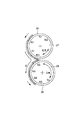
ここで、従来の現像スリーブを2本備えた多段磁気ブラシ現像方式の現像装置の例を図13に示す。 Here, FIG. 13 shows an example of a conventional multi-stage magnetic brush developing type developing device having two developing sleeves.
現像装置104は、感光体ドラム101と平行に配置された現像剤容器122を備え、その内部は、感光体ドラム101に平行な隔壁123によって現像室R1と撹拌室R2に区画される。現像室R1及び撹拌室R2内には、上記トナー粒子と磁性キャリアが混合された現像剤120が収容されている。
The developing
現像室R1内には搬送スクリュー124が収容されており、回転駆動により現像剤120を、現像剤容器122の感光体ドラム101に平行な長手方向に沿って搬送する。撹拌室R2内には搬送スクリュー125が収容されており、回転駆動により現像剤120を、現像剤容器122の感光体ドラム101に平行な長手方向に沿って搬送する。搬送スクリュー125による現像剤搬送方向は、搬送スクリュー124によるそれとは反対方向である。
A
隔壁123には、図14をも参照すると理解されるように、図3にて奥側と手前側にそれぞれ開口123a、123bが設けられている。搬送スクリュー124で搬送された現像剤120は、開口123aから搬送スクリュー125に受渡され、搬送スクリュー125で搬送された現像剤120が、開口123bから搬送スクリュー124に受渡される。
As can be understood by referring also to FIG. 14, the
現像剤容器122の感光体ドラム101に近接する部位には開口部が設けられ、該開口部に非磁性の材料で構成された第1の現像スリーブ126及び第2の現像スリーブ128の2本の現像剤担持体が設けられている。第1の現像スリーブ126は、感光体ドラム101と対向配置されて現像領域A1を形成し、第2の現像スリーブ128は、感光体ドラム101と対向配置されて現像領域A2を形成する。
An opening is provided in a portion of the
この2本の現像剤担持体のうち感光体ドラム101の回転方向aで上流側で対向配置された第1の現像スリーブ126は、矢印bの方向(感光体ドラム101回転方向aとは逆方向)に回転する。
Of the two developer carriers, the first developing
また、現像スリーブ126の回転方向で現像領域A1より上流に、本例では、現像剤容器122の開口部上端にブレード状の現像剤規制部材(層厚規制ブレード)121が配置される。現像スリーブ126は、保有する現像剤が層厚規制ブレード121にて適正な現像剤層厚に規制された後、現像剤120を第1の現像領域A1に担持搬送する。
Further, in the present example, a blade-like developer regulating member (layer thickness regulating blade) 121 is disposed at the upper end of the opening of the
現像スリーブ126内にはローラ状の第1の磁界発生手段(以後、「マグネットローラ」という。)127が固定配置されている。この第1のマグネットローラ127は、第1の現像領域A1に対向する現像磁極S1を有している。現像磁極S1が第1の現像領域A1に形成する現像磁界により現像剤の磁気ブラシが形成され、この磁気ブラシが、第1の現像領域A1で矢印a方向に回転する感光体ドラム101に接触して静電潜像をこの第1の現像領域A1で現像する。
A roller-shaped first magnetic field generating means (hereinafter referred to as “magnet roller”) 127 is fixedly arranged in the developing
第1のマグネットローラ127は、上記現像磁極S1の他にN1、S2、N2、N3極を有しており、このうちN2極とN3極は、現像剤容器122内で同極で隣り合っており反撥磁界を形成し、現像剤120に対してバリアが形成されている。
The
更に、上記第1の現像スリーブ126の下方部で、且つ、感光体ドラム101の回転方向aにて下流側に、第2の現像剤担持体である第2の現像スリーブ128が配置されている。しかも、第2の現像スリーブ128は、第1の現像スリーブ126及び感光体ドラム101の双方に略対向した領域に配置され、第1の現像スリーブ126と同方向の矢印c方向に回転可能に配設されている。
Further, a second developing
この第2の現像スリーブ128は、第1の現像スリーブ126と同様に非磁性材料で構成され、その内部には第2の磁界発生手段であるローラ状の第2のマグネットローラ129が非回転状態で設置されている。また、この第2のマグネットローラ129は、磁極S3、N4、S4、N5、S5の5極を有している。
The second developing
現像剤120の流れは、第1の現像スリーブ126をN2→S2→N1→S1→N3と搬送される。その後、第1の現像スリーブ126上の現像剤は第2の現像スリーブ128へと移動し、第2の現像スリーブ128上をS3→N4→S4→N5→S5と搬送される。本例では、現像剤の受渡は、略対向した異極同士(N3極とS3極)で行われる。これは、同極同士の場合は磁力線が形成されないので、安定した受渡が行えないからである。
The flow of the
このうち、第2の現像スリーブ128と感光体ドラム101の対向部、つまり第2の現像領域A2にて、N4極に形成された磁気ブラシが感光体ドラム101に接触している。そして、第1の現像領域A1を通過後の感光体ドラム101上の静電潜像に対し、更に2度目の現像を行う。このように、2回目の現像を行なうことにより、高い現像効率が達成される。
Among these, the magnetic brush formed in the N4 pole is in contact with the
上述のように、現像スリーブ126、128を2本設けた構成をとることで、例えば感光体ドラム101の周速度の高速化に伴い現像時間が短くなっても、高い現像効率が可能となり、現像濃度の低下や濃度ムラを発生することなく良好に画像形成ができる。
As described above, by adopting the configuration in which the two developing
ところで、現像剤容器122内の現像剤120は、容器122内での循環移動によって、現像スリーブ126、128の表面に沿って、図15(a)に示す現像スリーブ126、128の軸受け140の部分へ移送される。このため、現像剤が軸受け140の部分に侵入して、軸受け140内に溜ってその機能を阻害する。そして現像スリーブ126、128の円滑な回転を不可能としたり、現像剤が軸受け140の部分を通過して、現像剤容器122外に現像剤が漏れたり、飛散することがあった。
By the way, the
このような、現像スリーブの端部からの飛散に関しては、現像スリーブの両端部に弾性シール部材を取り付け、このシール部材端部からトナーが漏れないようにシールする方法が提案されている。 With regard to such scattering from the end of the developing sleeve, there has been proposed a method in which an elastic seal member is attached to both ends of the developing sleeve, and sealing is performed so that toner does not leak from the end of the seal member.
しかし、このシール構成では弾性シール部材を現像スリーブ外周面に圧設しているため、現像スリーブへの負荷が大きく、また弾性シール部材の劣化によりシール性が低下してしまうという問題もある。 However, in this seal configuration, since the elastic seal member is press-fitted on the outer peripheral surface of the developing sleeve, there is a problem that the load on the developing sleeve is large and the sealing performance is deteriorated due to the deterioration of the elastic seal member.
そこで、磁気吸着するトナー或いはキャリアを使用する現像装置にあっては、磁力発生手段によって磁気シールすることが考えられている(例えば、特許文献1参照)。 Therefore, in a developing device using a magnetically adsorbing toner or carrier, it is considered to magnetically seal with a magnetic force generating means (see, for example, Patent Document 1).
図15(b)に示すように、現像スリーブSLの表面と所定間隔を維持して対向する対向面に着磁した磁気シール部材MPを設け、現像剤を磁気吸着して保持する構成である。 As shown in FIG. 15B, a magnetic seal member MP that is magnetized is provided on the facing surface that is opposed to the surface of the developing sleeve SL while maintaining a predetermined distance, and the developer is magnetically attracted and held.
この磁気シール構成は、現像スリーブSLと磁気シール部材MPとが非接触であるために、現像スリーブSLの回転負荷を小さくし、また摩耗等による劣化を生じないために長寿命となる利点がある。 This magnetic seal configuration is advantageous in that since the developing sleeve SL and the magnetic seal member MP are not in contact with each other, the rotational load of the developing sleeve SL is reduced, and deterioration due to wear or the like does not occur, resulting in a long life. .
現像スリーブSLを非接触に包囲するように板状の磁石を磁気シール部材MPとして設けると、現像スリーブSL内のマグネットローラMRと磁石MPとの間に現像剤による磁気穂(磁気ブラシ)が形成されて漏れを防止できる。図13の現像装置104においては、磁石MPとして1面がN極でありその裏面がS極である磁石板を用いた場合は、マグネットローラの反撥磁界を形成する極(N2とN3、及び、S3とS5)と異極の面を現像スリーブ側の面とすることが望ましい。この構成としない場合には、スリーブ長手方向への現像剤漏れが生じやすい。その理由は、以下の通りである。
When a plate-like magnet is provided as the magnetic seal member MP so as to surround the developing sleeve SL in a non-contact manner, a magnetic brush (magnetic brush) is formed between the magnet roller MR and the magnet MP in the developing sleeve SL. To prevent leakage. In the developing
図16及び図17を参照して説明する。反撥磁界と磁気シール部材が同極で対向した場合、反撥磁界と磁気シール部材間にも反撥磁界が形成されてしまう。そのために、図16(a)に示すように、磁気シールの磁力線は、現像スリーブSLの長手方向外側に向かって曲がって伸びてしまう。この時、現像剤は、図16(b)に示すように磁力線に沿って配列されるため、現像剤が現像スリーブSLの端部方向に向かって伸び、端部方向に現像剤が抜け易くなっている。 This will be described with reference to FIGS. 16 and 17. When the repulsive magnetic field and the magnetic seal member face each other with the same polarity, a repellent magnetic field is also formed between the repellent magnetic field and the magnetic seal member. Therefore, as shown in FIG. 16A, the magnetic lines of force of the magnetic seal are bent and extended toward the outside in the longitudinal direction of the developing sleeve SL. At this time, since the developer is arranged along the lines of magnetic force as shown in FIG. 16B, the developer extends toward the end portion of the developing sleeve SL, and the developer is easily removed in the end portion direction. ing.
図16(c)は、磁気シール部材MPと現像スリーブSLに囲まれた領域で、磁性キャリアにかかる力を模式的に示す。矢印はその位置における力の方向、また、矢印の長さは力の大きさを表している。 FIG. 16C schematically shows the force applied to the magnetic carrier in the region surrounded by the magnetic seal member MP and the developing sleeve SL. The arrow indicates the direction of the force at that position, and the length of the arrow indicates the magnitude of the force.
同極で磁石が対向している場合、磁石と磁石の間には磁性キャリアに働く磁気力のほとんどない領域(磁石に働く力の方向が反転する領域)が磁石間の長手方向に連続して存在することとなる。図16(c)には、磁性キャリアに働く磁気力が小さくほとんどない領域を○印で示した。 When magnets are facing each other with the same polarity, a region where there is almost no magnetic force acting on the magnetic carrier (region where the direction of the force acting on the magnet is reversed) is continuous between the magnets. Will exist. In FIG. 16C, the region where the magnetic force acting on the magnetic carrier is small and almost absent is indicated by a circle.
しかし、この図16(c)に示すように、磁性キャリアに働く力のほとんどない領域が、磁気シール部材MPと現像スリーブSL間の長手方向に連続して存在する場合には、磁性キャリアが、磁気シール部材MPやマグネットローラMRに引かれることはない。そのために、図16(c)に示した点線矢印のような流れに従って漏れ出すことが可能となる。その結果、現像剤領域の外側に現像剤が流出しやすくなり、良好なシール性が発揮できなくなる。 However, as shown in FIG. 16 (c), when there is a region where there is almost no force acting on the magnetic carrier continuously in the longitudinal direction between the magnetic seal member MP and the developing sleeve SL, the magnetic carrier It is not pulled by the magnetic seal member MP or the magnet roller MR. Therefore, it becomes possible to leak in accordance with the flow as indicated by the dotted arrow shown in FIG. As a result, the developer easily flows out to the outside of the developer region, and good sealing performance cannot be exhibited.
そこで、反撥磁界と磁気シール部材を異極で対向させる構成が提案されている。 Therefore, a configuration has been proposed in which the repulsive magnetic field and the magnetic seal member are opposed to each other with different polarities.
つまり、異極で対向させると、図17(a)に示すように、磁気シールの磁力線は、現像スリーブ方向に伸びるので、長手方向外側に向かって伸びにくくなるため、現像剤は現像スリーブ端部方向に抜けにくくなる。この時、現像剤は、図17(b)に示すように現像剤が現像スリーブ方向にのび、現像スリーブSLと磁気シール部材MPの間に現像剤による磁気穂が形成される。この磁気穂が端部方向へ抜けようとする現像剤をシールする役目を担い、さらに漏れ出しにくくなる。 That is, when facing each other with a different polarity, as shown in FIG. 17A, the magnetic force lines of the magnetic seal extend in the direction of the developing sleeve, so that it is difficult to extend outward in the longitudinal direction. It becomes difficult to come off in the direction. At this time, as shown in FIG. 17B, the developer extends in the direction of the developing sleeve, and a magnetic spike is formed between the developing sleeve SL and the magnetic seal member MP. The magnetic ears serve to seal the developer that is about to escape in the direction of the end portion, and are more difficult to leak out.
一方、先に述べた同極で対向している場合は、図16(b)に示すように、磁気穂が磁気シール部材MPから現像スリーブ方向に伸びていかない。よって磁気シール部材MPと現像スリーブSL間に現像剤の存在しない領域が存在しており、現像剤が漏れやすくなっている。 On the other hand, when facing the same pole as described above, the magnetic spike does not extend from the magnetic seal member MP in the direction of the developing sleeve, as shown in FIG. Therefore, there is a region where no developer exists between the magnetic seal member MP and the developing sleeve SL, and the developer is likely to leak.
図17(c)は、磁気シール部材MPと現像スリーブSLに囲まれた領域で、磁性キャリアにかかる力を図16(c)と同様に模式的に示す。 FIG. 17C schematically shows the force applied to the magnetic carrier in the region surrounded by the magnetic seal member MP and the developing sleeve SL, as in FIG.
異極で磁石が対向している場合、磁石と磁石の間には磁性キャリアに働く磁気力のほとんどない領域(○印で示す)は存在するが磁石間に連続して存在することはない。そのため、磁気シール部材MPと現像スリーブSLに囲まれた領域の磁性キャリアは、現像スリーブ端部方向に移動する過程で、必ず磁気シール部材MPやマグネットローラMRに引かれる。その結果、現像領域の外側に現像剤が流出しにくくなり、良好なシール性が発揮できる。 When the magnets are opposed to each other with different polarities, there is a region between the magnets where there is almost no magnetic force acting on the magnetic carrier (indicated by a circle), but there is no continuous presence between the magnets. Therefore, the magnetic carrier in the region surrounded by the magnetic seal member MP and the developing sleeve SL is always pulled by the magnetic seal member MP and the magnet roller MR in the process of moving in the direction toward the end of the developing sleeve. As a result, the developer hardly flows out to the outside of the development area, and good sealing performance can be exhibited.
また、磁気シール部材MPとしてその内周面にNS極が多磁極に着磁された磁石を用いる構成も提案されている。このような構成では、磁気シール部材の多磁極間で磁力線が伸びるため、磁力線が現像スリーブの長手方向外側に伸びにくくなり、良好なシール性が発揮できる。
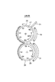
上記磁気シール構成を、図13に示す前記の現像スリーブを2本備えた磁気ブラシ現像装置に適用した場合には、以下のような問題が生じることがあった。 When the above magnetic seal configuration is applied to a magnetic brush developing device having two developing sleeves as shown in FIG. 13, the following problems may occur.
図18に示すように、磁気シール部材として1面がN極でありその裏面がS極である磁石板130、131を用いた場合は、上流現像スリーブ126は、反撥磁極(N2とN3)の異極であるS極面を内周面とする。また、下流現像スリーブ128は、反撥磁極(S3とS5)の異極であるN極面を内周面とする。先述の従来技術から考えると、斯かる構成とすることにより、現像領域の外側に現像剤が流出しにくくなり、良好なシール性が発揮できるように思われた。
As shown in FIG. 18, when
しかしながら、本発明者らの検討によれば、上記構成では、新たに、現像スリーブ端部における上流及び下流現像スリーブ126、128の間より、下流スリーブ回転方向に現像剤が漏れ出すことが分かった。これは以下の理由による。
However, according to the study by the present inventors, it has been found that in the above configuration, the developer leaks in the downstream sleeve rotation direction from between the upstream and
下流現像スリーブ128の反撥磁界を形成するS3極とS5極のうちS3極は上流現像スリーブ126より現像剤を受取る受渡極でもある。その結果、S3極の対向部には上流現像スリーブ126が存在するため、磁気シール部材131は、図18に示すように反撥磁界の途中までしか延ばすことができない。そのために、磁気シール部材131は、受渡極S3極には対向していない。
Of the S3 pole and S5 pole forming the repulsive magnetic field of the downstream developing
しかし、磁気シール部材131と受渡極S3極間には磁力線が形成されるため、磁気シール部材131で捕獲された現像剤の一部は受渡極S3極に引き寄せられ移動する。現像スリーブ端部の磁気シール部材131よりS3極に移動した現像剤は、S3極の対向には磁気シール部材がないこともあり、現像スリーブ端部方向に漏れ出す。この端部方向に漏れ出た現像剤は、現像スリーブの回転に伴って搬送され、上流、下流現像スリーブ126、128の間より漏れ出すこととなる。
However, since magnetic lines of force are formed between the
磁気シール部材としてその内周面にNS極が多磁極に着磁された磁石を用いる構成の場合も、磁気シール部材と受渡極S3極との間に磁力線が形成されるため、先の場合と同様、上流、下流現像スリーブの間より現像剤が漏れ出すこととなる。 Also in the case of using a magnet with NS poles magnetized to multiple magnetic poles on its inner peripheral surface as the magnetic seal member, a magnetic field line is formed between the magnetic seal member and the delivery pole S3 pole. Similarly, the developer leaks from between the upstream and downstream developing sleeves.
そこで、本発明の目的は、複数の現像剤担持体を備えた現像装置に対し、磁石部材を用いた現像剤担持体端部のシールを行なった際に、2つの現像剤担持体の間から現像剤担持体回転方向に現像剤が漏れないようにした現像装置を提供することである。 SUMMARY OF THE INVENTION Accordingly, an object of the present invention is to provide a developing device having a plurality of developer carriers from between the two developer carriers when sealing the end of the developer carrier using a magnet member. to provide a developing equipment which is adapted developer from leaking to the developer carrying member rotation direction.
上記目的は本発明に係る現像装置にて達成される。要約すれば、本発明は、磁性粒子を含む現像剤を担持搬送して像担持体上に形成された静電潜像を現像する第1現像剤担持体と、前記第1現像剤担持体の回転方向と同一方向に回転可能に設けられ、前記第1現像剤担持体から受け渡された現像剤を担持搬送して前記像担持体上に形成された静電潜像を現像する第2現像剤担持体と、前記第1現像剤担持体及び前記第2現像剤担持体を開口部にて一部露出させ、現像剤を収納する現像容器と、前記第1現像剤担持体内に配置され、少なくとも前記第2現像剤担持体に近接対向して設けられた第1磁極を含む複数の磁極を有する第1磁界発生部材と、前記第2現像剤担持体内に配置され、前記第1磁極と略対向して設けられ、前記第1磁極とは異極性の第2磁極を含む複数の磁極を有する第2磁界発生部材と、前記第1現像剤担持体の軸方向端部であって、前記第1現像剤担持体に対して前記像担持体と逆側に設けられ、かつ、前記前記第1磁極よりも前記第1現像剤担持体の回転方向下流側に設けられ、前記第1現像剤担持体の周面に沿って近接配置された第1磁石部材と、前記第2現像剤担持体の軸方向端部であって、前記第2現像剤担持体に対して前記像担持体と逆側に設けられ、かつ、前記前記第2磁極よりも前記第2現像剤担持体の回転方向上流側に設けられ、前記第2現像剤担持体の周面に沿って近接配置された第2磁石部材と、を有し、前記第1磁極と前記第2磁極とで形成される磁力により前記第1現像剤担持体から前記第2現像剤担持体に現像剤が受け渡される現像装置であって、
前記第2磁石部材の前記第2現像剤担持体に対向する面のうち、第2現像剤担持体回転方向下流側の端部領域を、前記第2磁極と同極性とし、
前記第2現像剤担持体の軸方向端部において、前記第2現像剤担持体の軸方向に関して前記第2磁石部材と対向するように設けられ、前記第2現像剤担持体の周面に沿って近接配置された磁性部材を有し、前記磁性部材が磁化されることで形成された磁気ブラシが前記第2現像剤担持体と接触することを特徴とする現像装置である。
The above object is achieved by the developing device according to the present invention. In summary, the present invention relates to a first developer carrier that develops an electrostatic latent image formed on an image carrier by carrying and conveying a developer containing magnetic particles, and the first developer carrier. Second development that is provided so as to be rotatable in the same direction as the rotation direction, and that develops the electrostatic latent image formed on the image carrier by carrying and transporting the developer delivered from the first developer carrier. A developer carrier, a part of the first developer carrier and the second developer carrier exposed at the opening, a developer container containing the developer, and the first developer carrier. A first magnetic field generating member having a plurality of magnetic poles including a first magnetic pole provided in close proximity to and opposed to the second developer carrier, and disposed in the second developer carrier and substantially the same as the first magnetic pole; A second magnet having a plurality of magnetic poles provided opposite to each other and including a second magnetic pole having a polarity different from that of the first magnetic pole. A generating member and an axial end of the first developer carrier, provided on the opposite side of the image carrier relative to the first developer carrier, and more than the first magnetic pole A first magnet member provided on the downstream side in the rotation direction of the first developer carrier and disposed in close proximity along a peripheral surface of the first developer carrier; and an axial end of the second developer carrier. Provided on the opposite side of the image carrier from the second developer carrier and upstream of the second magnetic pole in the rotation direction of the second developer carrier. And a second magnet member disposed close to the peripheral surface of the second developer carrying member, and the first developer carrying by the magnetic force formed by the first magnetic pole and the second magnetic pole. A developing device in which a developer is transferred from a body to the second developer carrier,
Of the surface of the second magnet member facing the second developer carrier, the end region on the downstream side in the second developer carrier rotation direction has the same polarity as the second magnetic pole,
An axial end of the second developer carrier is provided to face the second magnet member in the axial direction of the second developer carrier, along the circumferential surface of the second developer carrier. has a closely spaced magnetic member Te, said magnetic member is a developing device, wherein a magnetic brush formed by being magnetized in contact with said second developer carrying member.
本発明の他の態様によれば、磁性粒子を含む現像剤を担持搬送して像担持体上に形成された静電潜像を現像する第1現像剤担持体と、前記第1現像剤担持体の回転方向と同一方向に回転可能に設けられ、前記第1現像剤担持体から受け渡された現像剤を担持搬送して前記像担持体上に形成された静電潜像を現像する第2現像剤担持体と、前記第1現像剤担持体及び前記第2現像剤担持体を開口部にて一部露出させ、現像剤を収納する現像容器と、前記第1現像剤担持体内に配置され、少なくとも前記第2現像剤担持体に近接対向して設けられた第1磁極を含む複数の磁極を有する第1磁界発生部材と、前記第2現像剤担持体内に配置され、前記第1磁極と略対向して設けられ、前記第1磁極とは異極性の第2磁極を含む複数の磁極を有する第2磁界発生部材と、前記第1現像剤担持体の軸方向端部であって、前記第1現像剤担持体に対して前記像担持体と逆側に設けられ、かつ、前記前記第1磁極よりも前記第1現像剤担持体の回転方向下流側に設けられ、前記第1現像剤担持体の周面に沿って近接配置された第1磁石部材と、前記第2現像剤担持体の軸方向端部であって、前記第2現像剤担持体に対して前記像担持体と逆側に設けられ、かつ、前記前記第2磁極よりも前記第2現像剤担持体の回転方向上流側に設けられ、前記第2現像剤担持体の周面に沿って近接配置された第2磁石部材と、を有し、前記第1磁極と前記第2磁極とを結んだ磁力線により前記第1現像剤担持体から前記第2現像剤担持体に現像剤が受け渡される現像装置であって、
前記第2磁石部材の前記第2現像剤担持体に対向する面のうち、第2現像剤担持体回転方向下流側の端部領域を、前記第2磁極と同極性とし、
前記第2磁石部材と前記第2現像剤担持体との対向部において、前記第2磁石部材に捕捉された磁気ブラシが前記第2現像剤担持体と接触するように前記第2磁石部材の磁力のほうが前記第2磁界発生部材の磁力よりも大きく構成されていることを特徴とする現像装置が提供される。
According to another aspect of the present invention, a first developer carrier that carries and conveys a developer containing magnetic particles to develop an electrostatic latent image formed on the image carrier, and the first developer carrier. A developer which is rotatably provided in the same direction as the rotation direction of the body and which carries the developer delivered from the first developer carrier and develops the electrostatic latent image formed on the image carrier; (2) a developer carrying member, a part of the first developer carrying member and the second developer carrying member are exposed at an opening, and a developer container containing the developer is disposed in the first developer carrying member. A first magnetic field generating member having a plurality of magnetic poles including a first magnetic pole provided close to and opposed to the second developer carrier, and disposed in the second developer carrier, and the first magnetic pole. And a plurality of magnetic poles including a second magnetic pole different in polarity from the first magnetic pole. A magnetic field generating member and an axial end of the first developer carrier, provided on the opposite side of the image carrier relative to the first developer carrier, and from the first magnetic pole And a first magnet member provided on the downstream side in the rotation direction of the first developer carrier, and disposed close to the circumferential surface of the first developer carrier, and the axial direction of the second developer carrier. An end provided on the opposite side of the image carrier relative to the second developer carrier and upstream of the second magnetic pole in the rotation direction of the second developer carrier. And a second magnet member disposed close to the circumferential surface of the second developer carrying member, and the first developer carrying by a magnetic line connecting the first magnetic pole and the second magnetic pole. A developing device in which a developer is transferred from a body to the second developer carrier,
Of the surface of the second magnet member facing the second developer carrier, the end region on the downstream side in the second developer carrier rotation direction has the same polarity as the second magnetic pole,
The magnetic force of the second magnet member is such that the magnetic brush captured by the second magnet member is in contact with the second developer carrier at the opposing portion of the second magnet member and the second developer carrier. A developing device is provided in which is configured to be larger than the magnetic force of the second magnetic field generating member .
本発明によれば、下流現像剤担持体に近接配置した磁石部材において、下流現像剤担持体回転方向下流側の前記下流現像剤担持体に対向する面は、下流現像剤担持体の受渡磁極と同極とする。これにより、現像剤担持体回転方向の現像剤漏れを極めて有効に防止することができる。 According to the present invention, in the magnet member disposed close to the downstream developer carrier, the surface facing the downstream developer carrier on the downstream side in the rotation direction of the downstream developer carrier has a delivery magnetic pole of the downstream developer carrier. Same polarity. Thereby, the developer leakage in the rotation direction of the developer carrying member can be extremely effectively prevented.
以下、本発明に係る現像装置を図面に則して更に詳しく説明する。 Hereinafter will be described in more detail with reference to the developing equipment according to the present invention with reference to the drawings.
実施例1
先ず、図1を参照して、本発明に係る現像装置を備えた画像形成装置の一実施例の概略構成を説明し、その後、本発明の特徴部を構成する現像装置について説明する。本実施例にて、画像形成装置は、電子写真プロセスを利用したタンデム型の多色画像形成装置とされるが、本発明はこれに限定されるものではない。
Example 1
First, referring to FIG. 1, a schematic configuration of an embodiment of an image forming apparatus provided with a developing device according to the present invention will be described, and then a developing device constituting a characteristic part of the present invention will be described. In this embodiment, the image forming apparatus is a tandem multicolor image forming apparatus using an electrophotographic process, but the present invention is not limited to this.
本実施例によると、多色画像形成装置は、中間転写体としての中間転写ベルト7の回転方向(矢印R7方向)に沿って上流側から下流側にかけて複数の画像形成部(画像形成ステーション)が配設されている。本実施例では、画像形成部は、イエローY、マゼンタM、シアンC、ブラックKの4個の画像形成部P(PY、PM、PC、PK)にて構成される。
According to the present embodiment, the multicolor image forming apparatus includes a plurality of image forming units (image forming stations) from the upstream side to the downstream side along the rotation direction (arrow R7 direction) of the
各画像形成部P(PY、PM、PC、PK)はほぼ同様の構成であり、それぞれ像担持体としてドラム形の電子写真感光体、即ち、感光体ドラム1(1a、1b、1c、1d)を備えている。フルカラー画像において、感光体ドラム1(1a、1b、1c、1d)には、それぞれイエロー(Y)、マゼンタ(M)、シアン(C)、ブラック(K)の画像が形成される。 Each of the image forming portions P (PY, PM, PC, PK) has a substantially similar configuration, and a drum-shaped electrophotographic photosensitive member, that is, a photosensitive drum 1 (1a, 1b, 1c, 1d) as an image carrier. It has. In a full-color image, yellow (Y), magenta (M), cyan (C), and black (K) images are formed on the photosensitive drums 1 (1a, 1b, 1c, and 1d), respectively.
更に説明すると、感光体ドラム1(1a、1b、1c、1d)は、それぞれ矢印R1方向(図1中の時計回り)に回転駆動される。各感光体ドラム1(1a、1b、1c、1d)の周囲には、その回転方向に沿ってほぼ順に、帯電器(帯電手段)2(2a、2b、2c、2)d、露光装置(潜像形成手段)3(3a、3b、3c、3d)、現像装置(現像手段)4(4a、4b、4c、4d)が配置される。更に、各感光体ドラム1(1a、1b、1c、1d)の周囲には、その回転方向に沿って一次転写ローラ(一次転写手段)5(5a、5b、5c、5d)、及び、ドラムクリーナ(クリーニング装置)6(6a、6b、6c、6d)が配設されている。 More specifically, each of the photosensitive drums 1 (1a, 1b, 1c, 1d) is driven to rotate in the direction of arrow R1 (clockwise in FIG. 1). Around each of the photosensitive drums 1 (1a, 1b, 1c, 1d), a charger (charging means) 2 (2a, 2b, 2c, 2) d, an exposure device (latent) are arranged in almost the order along the rotation direction. An image forming unit 3 (3a, 3b, 3c, 3d) and a developing device (developing unit) 4 (4a, 4b, 4c, 4d) are arranged. Further, around each photosensitive drum 1 (1a, 1b, 1c, 1d), a primary transfer roller (primary transfer means) 5 (5a, 5b, 5c, 5d) and a drum cleaner are arranged along the rotation direction. (Cleaning device) 6 (6a, 6b, 6c, 6d) is provided.
中間転写ベルト7は、支持ローラ81、82、及び、駆動ローラも兼ねる二次転写対向ローラ8に張設されており、二次転写対向ローラ8の矢印R8方向の回転に伴って、矢印R7方向に回転移動する。この中間転写ベルト7の回転速度は、上述の各感光体ドラム1(1a、1b、1c、1d)の回転速度(プロセススピード)とほぼ同じに設定されている。
The
また、中間転写ベルト7は、その裏面側から一次転写ローラ5(5a、5b、5c、5d)によって押圧されていて、その表面を感光体ドラム1(1a、1b、1c、1d)に当接させている。中間転写ベルト7と各感光体ドラム1との間には、一次転写ニップ(一次転写部)T1(T1a、T1b、T1c、T1d)が形成されている。
Further, the
二次転写対向ローラ8に対応する位置には、二次転写ローラ(二次転写手段)9が配設されている。二次転写ローラ9は、二次転写対向ローラ8との間に中間転写ベルト7を挟持しており、二次転写ローラ9と中間転写ベルト7との間には、二次転写ニップ(二次転写部)T2が形成されている。
A secondary transfer roller (secondary transfer means) 9 is disposed at a position corresponding to the secondary transfer counter roller 8. The secondary transfer roller 9 holds an
画像形成に供される転写材Pは、給紙カセット10に積載された状態で収納されている。この転写材Pは、給紙ローラ、搬送ローラ、レジストローラ等を有する給搬送装置(いずれも不図示)によって、上述の二次転写ニップ部T2に供給される。
The transfer material P used for image formation is stored in a state of being stacked on the
転写材Pの搬送方向に沿っての二次転写ニップ部T2の下流側には、定着ローラ12とこれに加圧された加圧ローラ13とを有する定着装置11が配設されており、さらに定着装置11の下流側には、排紙トレイ(図示せず)が配設されている。
A fixing device 11 having a fixing
上述構成の画像形成装置においては、以下のようにして、転写材P上に4色フルカラーのトナー像が形成される。 In the image forming apparatus configured as described above, a four-color full-color toner image is formed on the transfer material P as follows.
先ず、感光体ドラム1(1a、1b、1c、1d)は、感光体ドラム駆動モータ(不図示)によって矢印R1方向に所定のプロセススピードで回転駆動され、帯電器2(2a、2b、2c、2d)によって所定の極性・電位に一様に帯電される。帯電後の感光体ドラム1(1a、1b、1c、1d)は、露光装置3(3a、3b、3c、3d)によって画像情報に基づく露光が行われ、露光部分の電荷が除去されて各色毎の静電潜像が形成される。 First, the photosensitive drum 1 (1a, 1b, 1c, 1d) is rotationally driven at a predetermined process speed in the direction of arrow R1 by a photosensitive drum drive motor (not shown), and the charger 2 (2a, 2b, 2c,. 2d) is uniformly charged to a predetermined polarity and potential. The charged photosensitive drum 1 (1a, 1b, 1c, 1d) is exposed based on image information by the exposure device 3 (3a, 3b, 3c, 3d), and the charge of the exposed portion is removed for each color. Electrostatic latent image is formed.
これら感光体ドラム1(1a、1b、1c、1d)上の静電潜像は、現像装置4(4a、4b、4c、4d)によってイエロー(Y)、マゼンタ(M)、シアン(C)、ブラック(K)の各色のトナー像として現像される。 The electrostatic latent images on the photosensitive drums 1 (1a, 1b, 1c, 1d) are converted into yellow (Y), magenta (M), cyan (C), and cyan by the developing devices 4 (4a, 4b, 4c, 4d). It is developed as a toner image of each color of black (K).
これら4色のトナー像は、一次転写ニップT1(T1a、T1b、T1c、T1d)において、一次転写ローラ5(5a、5b、5c、5d)により、中間転写ベルト7上に順次に一次転写される。こうして、4色のトナー像が中間転写ベルト7上で重ね合わされる。
These four color toner images are sequentially primary transferred onto the
一次転写時に、中間転写ベルト7に転写されないで感光体ドラム1(1a、1b、1c、1d)上に残ったトナー(残留トナー)は、ドラムクリーナ6(6a、6b、6c、6d)によって除去される。残留トナーが除去された感光体ドラム1(1a、1b、1c、1d)は、次の画像形成に供される。
During the primary transfer, the toner (residual toner) remaining on the photosensitive drum 1 (1a, 1b, 1c, 1d) without being transferred to the
上述のようにして中間転写ベルト7上で重ね合わされた4色のトナー像は、転写材Pに二次転写される。給紙カセット10から給搬送装置によって搬送された転写材Pは、レジストローラ(図示せず)によって中間転写ベルト7上のトナー像にタイミングを合わせるようにして二次転写ニップT2に供給される。供給された転写材Pには、二次転写ニップT2において、二次転写ローラ9により、中間転写ベルト7上の4色のトナー像が一括で二次転写される。
The four color toner images superimposed on the
4色のトナー像が二次転写された転写材Pは、定着装置11に搬送され、ここで加熱・加圧されて表面にトナー像が定着される。トナー像定着後の転写材Pは、排紙トレイ上に排出される。 The transfer material P onto which the four color toner images have been secondarily transferred is conveyed to the fixing device 11 where it is heated and pressurized to fix the toner image on the surface. The transfer material P after the toner image is fixed is discharged onto a paper discharge tray.
以上で、1枚の転写材Pの片面(表面)に対する4色フルカラーの画像形成が終了する。 The four-color full-color image formation on one surface (front surface) of one transfer material P is thus completed.
ここで、図2及び図3を用いて本実施例の現像装置4について詳述する。なお、本実施例の画像形成装置本体に用いられる各現像装置4a、4b、4c、4dは同一の構成を備えているので、一つの現像装置4についてのみ説明を行う。以下の説明で、現像装置4といえば、現像装置4a、4b、4c、4dのいずれをも指している。
Here, the developing
本実施例にて、現像装置4は、先に図13を参照して説明した、現像剤担持体としての現像スリーブを2本備えた、多段磁気ブラシ現像方式の現像装置と同様の構成とされる。
In this embodiment, the developing
つまり、本実施例にて、現像装置4は、現像剤容器22を備え、その内部は隔壁23によって現像室R1と撹拌室R2に区画される。一方、現像室R1及び撹拌室R2内には、現像剤20が収容されている。本実施例で、現像剤は、トナー粒子と磁性キャリア(即ち、磁性粒子)が混合された二成分現像剤とされる。本実施例で用いる磁性キャリアは、フェライトキャリアや、バインダ樹脂と磁性金属酸化物及び非磁性金属酸化物からなる樹脂磁性キャリア等を用いればよい。
That is, in this embodiment, the developing
現像室R1内には搬送スクリュー24が収容されており、回転駆動により現像剤20を、現像剤容器22の感光体ドラム1に平行な長手方向に沿って搬送する。撹拌室R2内には搬送スクリュー25が収容されており、回転駆動により現像剤20を、現像剤容器22の感光体ドラム1に平行な長手方向に沿って搬送する。搬送スクリュー25による現像剤搬送方向は、搬送スクリュー24によるそれとは反対方向である。
A conveying
隔壁23には、図3に示すように、図2にて奥側と手前側とにそれぞれ開口23a、23bが設けられている。搬送スクリュー24で搬送された現像剤20は、開口23aから搬送スクリェー25に受渡され、搬送スクリュー25で搬送された現像剤20が、開口23bから搬送スクリュー24に受渡される。
As shown in FIG. 3, the
現像剤容器22の感光体ドラム1に近接する部位には開口部が設けられ、該開口部に非磁性の材料で構成された第1の現像スリーブ26及び第2の現像スリーブ28の2本の現像剤担持体が設けられている。本実施例にて、第1及び第2の現像スリーブ26、28は、アルミニウムや非磁性ステンレス鋼等の材質で作製され、その表面に適度な凹凸が形成されている。
An opening is provided in a portion of the
また、第1の現像剤担持体である上流の現像スリーブ26は、感光体ドラム1と対向配置されて現像領域A1を形成し、第2の現像剤担持体である下流の現像スリーブ28は、感光体ドラム1と対向配置されて現像領域A2を形成する。
The upstream developing
この2本の第1及び第2の現像剤担持体のうち、感光体ドラム1の回転方向aで上流側で対向配置された上流の現像スリーブ26は、矢印bの方向(感光体ドラム1回転方向aとは逆方向)に回転する。
Of the two first and second developer carriers, the upstream developing
また、現像スリーブ26の回転方向で現像領域A1より上流に、本実施例では、現像剤容器22の開口部上端にブレード状の現像剤規制部材(層厚規制ブレード)21が配置される。現像スリーブ26は、保有する現像剤が層厚規制ブレード21にて適正な現像剤層厚に規制された後、現像剤20を上流の現像領域A1に担持搬送する。
Further, in the present embodiment, a blade-like developer regulating member (layer thickness regulating blade) 21 is disposed at the upper end of the opening of the
上流の現像スリーブ26内にはローラ状の第1の磁界発生手段である第1のマグネットローラ27が固定配置されている。この第1のマグネットローラ27は、第1の現像領域A1に対向する現像磁極S1を有している。現像磁極S1が、第1の現像領域A1に形成する現像磁界により現像剤の磁気ブラシが形成され、この磁気ブラシが第1の現像領域A1で矢印a方向に回転する感光体ドラム1に接触して静電潜像をこの第1の現像領域A1で現像する。その際、磁気ブラシに付着しているトナーと、現像スリーブ表面に付着しているトナーも、該静電潜像の画像領域に転移して現像する。本実施例では、第1のマグネットローラ27は、上記現像磁極S1の他にN1、S2、N2、N3極を有している。このうちN2極とN3極は同極で隣り合っており反撥磁界が形成されるため、現像剤に対してバリアが形成されている。
In the upstream developing
上述のように、上流の現像スリーブ26の下方部であって、上流現像スリーブ26及び感光体ドラム1の双方に略対向した領域に、第2の現像剤担持体である下流の現像スリーブ28が配置されている。下流の現像スリーブ28は、矢印c方向(上流現像スリーブ26とは同一方向)に回転可能に配設されている。上述のように、この下流現像スリーブ28もまた、上流現像スリーブ26と同様に非磁性材料で構成され、その内部にはローラ状の磁界発生手段である第2のマグネットローラ29が非回転状態で設置されている。この第2のマグネットローラ29は、磁極S3、N4、S4、N5、S5の5極を有している。このうち、N4極上の磁気ブラシは第2の現像領域A2で感光体ドラム1に接触しており、第1の現像領域A1を通過後の感光体ドラム1に対し、更に2度目の現像を行う。
As described above, the downstream developing
また、S3極とS5極は同極であり、S3極とS5極の間には反発磁界が形成され、現像剤に対してバリアが形成されている。このうちS3極は、上流現像スリーブ26に内包された第1のマグネットローラ27のN3極に、両スリーブが最も接近している位置の近傍で対向している。
Further, the S3 pole and the S5 pole are the same pole, a repulsive magnetic field is formed between the S3 pole and the S5 pole, and a barrier is formed against the developer. Of these, the S3 pole faces the N3 pole of the
以下、現像剤の流れを、上流の現像スリーブ26と下流の現像スリー28付近の拡大図(図4)を用いて説明する。
Hereinafter, the flow of the developer will be described with reference to an enlarged view (FIG. 4) in the vicinity of the upstream developing
上流現像スリーブ26のN3極とN2極間には反発磁界が形成されおり、また、下流現像スリーブ28のS3極とS5極間にも反発磁界が形成されている。従って、第1の現像スリーブ26上を搬送され現像領域を通過してきた現像剤は、N3極へ至り、反発磁界によって両スリーブの最近接位置を通過することができない。現像剤は、矢印dのようにN3極からS3極方向へ延びる磁力線に従って下流現像スリーブ28側へ移動し、下流現像スリーブ28上を攪拌室R2内の搬送スクリュー25まで搬送される。
A repulsive magnetic field is formed between the N3 pole and the N2 pole of the upstream developing
本実施例のように上流現像スリーブ26の下に下流現像スリーブ28を設けることで、現像剤の流れは上流現像スリーブ26をN2→S2→N1→S1→N3と搬送される。その後、上流現像スリーブ26上の現像剤は、両スリーブ26、28の反発磁界によりブロックされ、下流現像スリーブ28へと移動する。そして、現像剤は、下流現像スリーブ28上をS3→N4→S4→N5→S5と搬送され、S5極で反発磁界にブロックされ、攪拌室R2へと剥ぎ落とされる。
By providing the downstream developing
なお、受渡極であるN3とS3は、完全に対向している必要はない。完全に対向している状態から45°のズレの範囲内で略対向していれば、現像剤の受渡はスムーズに行うことが可能である。 The delivery poles N3 and S3 do not have to be completely opposed. The developer can be delivered smoothly as long as it is substantially opposed within the range of 45 ° from the completely opposed state.
ここで、図5及び図6を参照して、本実施例における磁気シール部分を詳しく述べる。 Here, with reference to FIG.5 and FIG.6, the magnetic seal part in a present Example is described in detail.
現像スリーブ26、28に沿って非接触状態で近接して、磁石部材、即ち、本実施例では、板状の磁石(磁石板)30、31を磁気シール部材として配置する。この構成によって、現像スリーブ26、28内のマグネットローラ27、29と磁気シール部材である磁石30、31との間に現像剤による磁気穂を形成することによって、漏れを防止できる。
Magnet members, that is, in this embodiment, plate-like magnets (magnet plates) 30 and 31 are arranged as magnetic seal members in proximity to the developing
ここで、磁石、即ち、磁気シール部材30、31として1面がN極でありその裏面がS極である磁石板を用いる。また、図5に比較例として示すように、磁気シール部材30、31は、上流、下流現像スリーブ26、28内部のマグネットローラ27、29の反撥磁界を形成する極(N2とN3、及び、S3とS5)と異極の面を現像スリーブ側の面とする。この場合には、現像スリーブ26、28内のマグネットローラ27、29と磁気シール部材30、31である磁石との間に磁力線が延びて、現像剤による磁気穂が形成され、漏れを防止できる。
Here, as the magnets, that is, the
しかしながら、「発明が解決する課題」でも述べたように、上記構成では、現像スリーブ26、28の端部方向への漏れ防止は良好となるが、現像スリーブ端部における上流現像スリーブ26と下流現像スリーブ28間から現像剤が漏れ出し易い。これは以下の理由による。
However, as described in “Problems to be solved by the invention”, in the above configuration, the leakage prevention toward the end portions of the
下流現像スリーブ28の反撥磁界を形成するS3極とS5極のうちS3極は、上流現像スリーブ26より現像剤を受取る受渡極でもある。その結果、受渡極S3極の対向部には上流現像スリーブ26が存在するため、磁気シール部材31は、図5に示すように反撥磁界の途中までしか磁気シール部材を伸ばすことができない。そのために、受渡極S3極には磁気シール部材31が対向していない。しかし、磁気シール部材31と受渡極S3極は異極同士であり、磁気シール部材31と受渡極S3極間には磁力線が形成される。そのため、磁気シール部材31で捕獲された現像剤の一部は受渡極S3極に引き寄せられ移動する。現像スリーブ端部の磁気シール部材31よりS3極に移動した現像剤は、S3極の対向には磁気シール部材31がないこともあり、現像スリーブ28端部方向に漏れ出す。この漏れ出した現像剤は、現像スリーブ28の回転に伴って搬送され、上流、下流現像スリーブ26、28の間より漏れ出すこととなる。
Of the S3 and S5 poles that form the repulsive magnetic field of the downstream developing
上記のような上流、下流現像スリーブ26、28間の空間からの現像剤の漏れを防止するには、下流現像スリーブ28の磁気シール部材31と受渡極S3極間に磁力線が形成されないようにしなければならない。そのためには、磁気シール部材31として1面がN極でありその裏面がS極である磁石板を用いた場合は、図6に示すように、受渡極S3極と同極であるS極を現像スリーブ対向面とする必要がある。
In order to prevent the leakage of the developer from the space between the upstream and downstream developing
ただし、図6に示す構成では、磁気シール部材31として、下流現像スリーブ28の反撥磁界を形成するS3極及びS5極と同極のS極面が対向しているため、S3極やS5極と磁気シール部材31間にも反撥磁界が形成されてしまう。そのため、各磁極の関係によっては、現像スリーブ長手方向の磁気シール部材31によるシール性の問題が懸念される。
However, in the configuration shown in FIG. 6, the S3 pole and the S5 pole are the same as the S3 pole and the S5 pole that form the repulsive magnetic field of the downstream developing
そこで、上記問題を解決するために、本実施例においては磁性板32を、図7に示すように、現像剤容器22の両側の側壁22aの内面に、現像スリーブ28の端部の周面を非接触に包囲する磁性板32を取り付けている。上流の現像スリーブ26に関しても同様の構成とすることができる。
Therefore, in order to solve the above problem, in this embodiment, as shown in FIG. 7, the
先ず、下流の現像スリーブ28に関連して説明する。上流の現像スリーブ26については後述する。
First, the downstream developing
下流現像スリーブ28の端部に配置した磁性板32は、現像スリーブ28内のマグネットローラ29の磁力及び磁気シール部材である磁石31の磁力によって磁化される。これにより、磁性板32とマグネットローラ29との間に磁気回路が形成されて、図8(a)に磁力線を示すように、下流現像スリーブ28側の磁性板32の先端部に磁界が集中する。
The
この磁界により、図8(b)に示すように、磁性板32と下流現像スリーブ28及び磁気シール部材31との間の空隙に現像剤による密な磁気穂(磁気ブラシ)が形成される。この磁気ブラシは端部シールとしての機能を有し、現像剤容器22内での往復循環により、現像スリーブ28の表面に沿って現像剤容器22内から移送されてくる現像剤を、磁気ブラシが磁性板32と現像スリーブ29との間で遮断する作用をなす。
Due to this magnetic field, as shown in FIG. 8B, a dense magnetic brush (magnetic brush) is formed by a developer in the gap between the
さらに、図8(c)には、磁気シール部材である磁石板31と現像スリーブ28に囲まれた領域で、磁性キャリアにかかる力を模式的に示した。
Further, FIG. 8C schematically shows the force applied to the magnetic carrier in a region surrounded by the
従来例における図16(c)、図17(c)と同様、矢印はその位置における力の方向、また、矢印の長さは力の大きさを表している。同極で磁石が対向している場合、磁石と磁石の間には磁性キャリアに働く力のほとんどない領域(磁石に働く磁気力の方向が反転する領域)が磁石間に連続して存在することとなる(従来例図16(c)参照)。 As in FIGS. 16C and 17C in the conventional example, the arrow indicates the direction of the force at the position, and the length of the arrow indicates the magnitude of the force. When magnets are facing each other with the same polarity, there is a continuous area between the magnets where there is almost no force acting on the magnetic carrier (area where the direction of the magnetic force acting on the magnet is reversed). (See FIG. 16C for the conventional example).
しかし、本実施例のように、磁性板32を有効に配置することで、磁性キャリアに働く磁気力のほとんどない領域(図中○印で示した)を連続して存在させないことが可能となる。
However, as in this embodiment, by effectively arranging the
このように、本実施例では、磁性板32を配置することで、磁性キャリアに働く力のほとんどない領域、即ち、磁性キャリアにかかる磁気力が小さな領域が、磁気シール部材31と、現像スリーブ28及び磁性板32との間に長手方向に連続して存在させないようにする。これによって、本実施例では、磁気シール部材31と、現像スリーブ28及び磁性板32とに囲まれた領域の磁性キャリアは、現像スリーブ28の端部方向に移動する過程で、必ず磁気シール部材31や現像スリーブ28内部のマグネットローラ29に引かれる。その結果、現像領域の外側に現像剤が流出しにくくなり、良好なシール性が発揮できる。
As described above, in the present embodiment, by arranging the
なお、本実施例においては、図7に示すように、磁性板32は、磁気シール部材31より現像剤容器22側に0.3mmの間隔(g1)をもって配置した。また、磁気シール部材31と同様、現像スリーブ28を非接触で囲むように0.5mmの一定ギャップ(g2)となるように配置した。なお、現像スリーブ28表面と磁気シール部材31の間隔(g3)は1mmである。また、磁気シール部材31としては、60mT(テスラ)のものを用いた。
In this embodiment, as shown in FIG. 7, the
ただし、磁性板32の配置に関しては、上記条件には限定されることはない。磁気シール部材31と現像スリーブ28で囲まれた領域において、磁性キャリアに働く力のほとんどない領域を現像スリーブ長手方向に沿って連続して存在させないように磁性板32を配置している限りは、漏れを防止することが可能である。
However, the arrangement of the
なお、磁性体である磁性キャリア(磁性粒子)にはたらく力(磁気力)Fは以下のように測定することができる。 The force (magnetic force) F acting on the magnetic carrier (magnetic particle) which is a magnetic material can be measured as follows.
磁気力Fは外部磁界(磁束密度)をBとして以下の式にて表せる。なお、これまで、現像スリーブ長手方向及び現像スリーブの表面に垂直方向の2次元で話を進めてきたが、実際には現像スリーブの周方向も考慮する必要があるため、磁気力の測定も3次元で行う必要がある。
F=(m・▽)B
ただし、F=(Fx,Fy,Fz)
この時、磁気力大きさは、
|F|=(Fx2+Fy2+Fz2)1/2
ここで、上記式中の磁性キャリア中の磁気双極子モーメントmは、一般的に外部磁界に比例した磁化を持つので、以下のように表せる。
m=|A|B
F=|A|(B・▽)B
=−|A|▽B2
Fx(x,y,z)=−|A|{B2(x,y,z)−B2(x+Δx,y,z)}/Δx
Fy(x,y,z)=−|A|{B2(x,y,z)−B2(x,y+Δy,z)}/Δy
Fz(x,y,z)=−|A|{B2(x,y,z)−B2(x,y,z+Δz)}/Δz
ただし、|A|は透磁率などを含む関数であり、キャリアが球形の場合は以下のように表せる。
|A|=(4π/μ0) ×(μ−1)/(μ−2) ×r3
ここで、rはキャリアの半径、μはキャリアの比透磁率、μ0は真空透磁率である。
The magnetic force F can be expressed by the following equation where B is an external magnetic field (magnetic flux density). Up to now, the discussion has been made in two dimensions in the longitudinal direction of the developing sleeve and in the direction perpendicular to the surface of the developing sleeve. Need to do in dimension.
F = (m ・ ▽) B
Where F = (Fx, Fy, Fz)
At this time, the magnitude of the magnetic force is
| F | = (Fx 2 + Fy 2 + Fz 2 ) 1/2
Here, since the magnetic dipole moment m in the magnetic carrier in the above formula generally has magnetization proportional to the external magnetic field, it can be expressed as follows.
m = | A | B
F = | A | (B ・ ▽) B
=-| A | ▽ B 2
Fx (x, y, z) = − | A | {B 2 (x, y, z) −B 2 (x + Δx, y, z)} / Δx
Fy (x, y, z) = − | A | {B 2 (x, y, z) −B 2 (x, y + Δy, z)} / Δy
Fz (x, y, z) = − | A | {B 2 (x, y, z) −B 2 (x, y, z + Δz)} / Δz
However, | A | is a function including magnetic permeability, and can be expressed as follows when the carrier is spherical.
| A | = (4π / μ 0 ) × (μ−1) / (μ−2) × r 3
Here, r is the radius of the carrier, μ is the relative magnetic permeability of the carrier, and μ 0 is the vacuum magnetic permeability.
以上から磁界の強さ|B|(={Bx2+By2+Bz2}1/2)に変化がある場合、磁束密度の小さい地点から磁束密度の大きな方向に向かい磁気力が生じることが分かる。逆に磁界の強さ|B|に変化がない方向には磁気力が働かないといえる。 From the above, it can be seen that when there is a change in the magnetic field strength | B | (= {Bx 2 + By 2 + Bz 2 } 1/2 ), a magnetic force is generated from a point where the magnetic flux density is small toward a direction where the magnetic flux density is large. Conversely, it can be said that the magnetic force does not work in the direction in which the magnetic field strength | B | does not change.
したがって、磁気シール部材31と現像スリーブ28で囲まれた領域において、磁界の大きさ(磁束密度)を連続的に測定していけば、その差分より上記式を元に磁気力Fの大きさ及び方向を求めることが可能である。
Therefore, if the magnitude of the magnetic field (magnetic flux density) is continuously measured in the region surrounded by the
外部磁界の大きさ(磁束密度)|B|は、市販のガウス(テスラ)メータで測定することが可能である。本発明者らはベル社製ガウスメータ モデル640を用いた。ガウスメータによりプローブ先端部における1方向の磁束密度の測定が可能なため、x軸、y軸、z軸の3種類のプローブを用いて3方向の磁束密度(BxとByとBz)を測定し、その結果より磁界の強さを導き出した。このように、磁束密度の測定を繰り返すことにより、磁界の強さの分布を導き、その結果を元に磁気力Fの大きさ及び方向を求めた。測定の際のΔx、Δy、Δzは250μmとして、測定を行った。Δx、Δy、Δzに関しては、
小さくすればする程磁界の分布は正確に把握できるが、測定に時間がかかる問題がある。一方、大きくすると正確な磁界の分布を把握することができない。100〜300μm程度が適当である。
The magnitude of the external magnetic field (magnetic flux density) | B | can be measured with a commercially available Gauss (Tesla) meter. The inventors used a Gauss meter model 640 manufactured by Bell. Since it is possible to measure the magnetic flux density in one direction at the tip of the probe with a gauss meter, the magnetic flux density (Bx, By, and Bz) in three directions is measured using three types of probes, x-axis, y-axis, and z-axis. As a result, the strength of the magnetic field was derived. Thus, by repeating the measurement of the magnetic flux density, the magnetic field strength distribution was derived, and the magnitude and direction of the magnetic force F were obtained based on the result. The measurement was performed with Δx, Δy, and Δz in the measurement being 250 μm. Regarding Δx, Δy, Δz,
The smaller the value, the more accurately the distribution of the magnetic field can be grasped, but there is a problem that the measurement takes time. On the other hand, if the value is increased, an accurate magnetic field distribution cannot be grasped. About 100-300 micrometers is suitable.
なお、磁性体以外の部材は測定に影響を与えないので、測定はマグネットローラ、磁石板、磁性板のみで行った。つまり、現像スリーブのない状態で、実際の配置を再現して行った。これにより、狭い領域での磁束密度測定が可能となるだけでなく、現像スリーブ内部の磁気力も把握することもできる。その際、プローブはxyzステージに固定し、移動させながら連続的に測定を行った。 In addition, since members other than the magnetic material do not affect the measurement, the measurement was performed using only the magnet roller, the magnet plate, and the magnetic plate. That is, the actual arrangement was reproduced without the developing sleeve. Thereby, not only can the magnetic flux density be measured in a narrow area, but also the magnetic force inside the developing sleeve can be grasped. At that time, the probe was fixed to the xyz stage and continuously measured while being moved.
上記測定結果及び上記式を元にキャリアに働く磁気力が求まる。 The magnetic force acting on the carrier is obtained based on the measurement result and the above formula.
例えば、半径が17.5μm、比透磁率μが12、真比重ρが4.8g/cm3の球形と近似したキャリアの場合、真空の透磁率は4π×10-7なため、|A|=2.46×10-6m3となり、磁界の強さの2乗B2の測定値を元に磁気力が求まる。
Fx=|A|ΔBx2/Δx
=(2.5×10⁻⁶)/(2.5×10-4)×ΔBx2
=10-2×ΔBx2(N)
=10-2×(Bx 2−Bx+Δx 2)(N)
磁界の強さの2乗の差分なので、磁界の強さが大きいほど、また差が大きいほど磁気力は大きくなる。磁界の強さが小さい場合は差がある程度大きくても磁気力は小さい。これは実際の現象と一致する。
For example, in the case of a carrier approximated to a sphere having a radius of 17.5 μm, a relative permeability μ of 12, and a true specific gravity ρ of 4.8 g / cm 3 , the vacuum permeability is 4π × 10 −7 , and thus | A | = 2.46 × 10 −6 m 3 , and the magnetic force is obtained based on the measured value of the square B 2 of the magnetic field strength.
Fx = | A | ΔBx 2 / Δx
= (2.5 × 10 −6 ) / (2.5 × 10 −4 ) × ΔBx 2
= 10 -2 × ΔBx 2 (N)
= 10 -2 × (B x 2 -B x + Δ x 2) (N)
Since the difference is the square of the strength of the magnetic field, the magnetic force increases as the strength of the magnetic field increases and the difference increases. Even to some extent large difference when the intensity of the magnetic field is small again the magnetic force is small. This is consistent with the actual phenomenon.
上記式より求まったキャリアの受ける磁気力が小さければ、キャリアは磁気シール部において磁気的拘束力が弱く、現像スリーブ端部において、そのように磁気力の小さな領域が現像スリーブスラスト方向に連続して存在する場合、漏れが生じる可能性が高い。 If the magnetic force received by the carrier obtained from the above equation is small, the carrier has a weak magnetic binding force at the magnetic seal portion, and such a small magnetic force region continues in the developing sleeve thrust direction at the end of the developing sleeve. If present, there is a high probability of leakage.
本発明者らの検討によれば、Fxが1×10⁻⁶(N)より小さくなると、拘束力は小さく漏れ始める場合がある。 According to the study by the present inventors, when Fx is smaller than 1 × 10 −6 (N), the restraining force may be small and start to leak.
例えば、磁界の強さが100mTから90mTに変化する場合は、
F=10-2×{(100×10-3)2−(90×10-3)2}=1.9×10⁻⁵
となり、この場合は磁気力がまだ或る程度はあるといえる。
For example, if the magnetic field strength changes from 100 mT to 90 mT,
F = 10 −2 × {(100 × 10 −3 ) 2 − (90 × 10 −3 ) 2 } = 1.9 × 10 −5
In this case, it can be said that there is still some magnetic force.
一方、磁界の強さが12mTから2mTに変化した場合は、磁界の強さの差は10mTと、先の例と同じである。しかし、
F=10-2×{(12×10-3)2−(2×10⁻³)2}=1.4×10⁻⁶
となり、磁気力は小さくなった。これは磁界の強さそのものが小さくなったことによる。
On the other hand, when the magnetic field strength changes from 12 mT to 2 mT, the difference in magnetic field strength is 10 mT, which is the same as the previous example. But,
F = 10 −2 × {(12 × 10 −3 ) 2 − (2 × 10 −3 ) 2 } = 1.4 × 10 −6
The magnetic force became smaller. This is because the strength of the magnetic field itself has become smaller.
ここで、さらに磁界の強さの差が5mTに小さくなった場合、つまり磁界の強さが12mTから7mTに変化した場合について考える。すると、
F=10-2×{(12×10-3)2−(7×10⁻³)2}=9.5×10⁻⁷
となる。つまり、キャリアに働く磁気力がさらに小さくなり、1×10⁻⁶(N)より小さくなるため、漏れが生じやすくなるといえる。
Here, consider the case where the difference in magnetic field strength is further reduced to 5 mT, that is, the case where the magnetic field strength is changed from 12 mT to 7 mT. Then
F = 10 −2 × {(12 × 10 −3 ) 2 − (7 × 10 −3 ) 2 } = 9.5 × 10 −7
It becomes. That is, the magnetic force acting on the carrier is further reduced and becomes smaller than 1 × 10 −6 (N), so that leakage can easily occur.
なお、以上は1次元で計算したが、実際には3次元で計算する必要がある。また、正確な測定にはΔx、Δy、Δzをできるだけ小さくする必要があるが、実際には測定装置自
体にも限界がある。
Although the above calculation is performed in one dimension, it is actually necessary to calculate in three dimensions. In addition, Δx, Δy, and Δz need to be as small as possible for accurate measurement, but there are actually limitations on the measuring device itself.
そこで、測定された磁気力の分布から、磁気力が1×10⁻⁶(N)未満の領域が現像スリーブのスラスト(長手)方向に連続して存在していると想定される場合は、漏れが生じる可能性がある。従って、スラスト方向の漏れを防止するためには、磁気力が1×10⁻⁶(N)以上の領域が、磁気シール部材31の表面と現像スリーブ28の表面の両方に接して存在すれば良い。これにより、磁気力が1×10⁻⁶(N)未満の領域が現像スリーブのスラスト(長手)方向に連続して存在できない事になる。すなわち、磁性粒子をトラップする能力を持った領域が、磁気シール部材31の表面と現像スリーブ28の表面間に連続して存在することで、長手方向のシール性が確保できる。
Therefore, if it is assumed from the distribution of the measured magnetic force that a region where the magnetic force is less than 1 × 10 −6 (N) exists continuously in the thrust (longitudinal) direction of the developing sleeve, May occur. Therefore, in order to prevent leakage in the thrust direction, a region having a magnetic force of 1 × 10 −6 (N) or more should be in contact with both the surface of the
上記構成によって、現像スリーブ端部の磁気シール性を確保しつつ、上流、下流現像スリーブ間からの現像剤の漏れも防止することが可能となる。 With the above configuration, it is possible to prevent leakage of the developer from between the upstream and downstream developing sleeves while ensuring the magnetic sealability at the end of the developing sleeve.
なお、本実施例においては、図6に示したように、磁気シール部材である磁石31を反撥磁界を形成するS5極のさらにスリーブ回転方向上流に位置するN5極対向部まで伸ばしている。これにより、N5極においては磁気シール部材31が異極で対向することとなるので、より積極的に磁気シール性を確保できる。また、このように異極で対向する部分が存在すると、その位置では磁石板31と現像スリーブ内のマグネットローラ29間に直接磁力線が伸びるので、磁気シールされた現像剤が現像スリーブ側へ、つまり現像剤容器内へスムーズに戻される。上記観点から、異極で対向する領域を1箇所以上設けておくことは、磁気シール部分に現像剤を溜めないためにも重要である。
In the present embodiment, as shown in FIG. 6, the
なお、これまで下流現像スリーブ28に関して主に述べたので、上流現像スリーブ26に関して述べておく。
Since the description has been made mainly on the downstream developing
本実施例では、下流現像スリーブ28の場合は、磁気シール部材31として1面がN極でありその裏面がS極である磁石板を用いている。この場合、上述したように、下流現像スリーブ28内部のマグネットローラ29の反撥磁界を形成する極(S3とS5)と異極の面を現像スリーブ側の面とすると、現像スリーブ端部における上流、下流現像スリーブ26、28間から現像剤が漏れ出した。
In the present embodiment, in the case of the downstream developing
しかしながら、上流現像スリーブ26に関しては、磁気シール部材30として、上流現像スリーブ26内部のマグネットローラ27の反撥磁界を形成する極(N2とN3)と異極の面を現像スリーブ側の面とする。この構成によっても現像スリーブ端部における上流、下流現像スリーブ26、28間から現像剤が漏れ出すことはない。
However, regarding the upstream developing
何故なら、下流現像スリーブ28の場合と同様、磁気シール部材30と上流現像スリーブ26の受渡極N3極との間には磁力線が形成され、現像剤が受渡極N3極にもっていかれる。しかし受渡極N3極の位置での現像スリーブの回転方向が、下流現像スリーブ28の受渡極S3極における回転方向と異なり、現像剤容器内に現像剤を搬送する方向に回転している。よって現像スリーブ端部方向に漏れ出した現像剤もうまく現像剤容器22内に回収される。
This is because, as in the case of the downstream developing
そのため、上流現像スリーブ26に関しては、磁気シール部材30として、上流現像スリーブ26内部のマグネットローラ27の反撥磁界を形成する極(N2とN3)と異極の面を現像スリーブ側の面としても問題はない。
Therefore, with respect to the upstream developing
そこで、本実施例においては、現像スリーブ26の磁気シール部材である磁石板30に関しては、マグネットローラ27の反撥磁界(N2、N3)と異極の面、すなわち、S極を現像スリーブ側の面とした。これは、マグネットローラ27と磁気シール部材30との間に積極的に磁力線を形成することで、より漏れを防止できるからである。
Therefore, in the present embodiment, with respect to the
本実施例においては、下流現像スリーブ28の端部シールに用いた磁性板32を上流現像スリーブ26の周囲まで延長している。これも、より積極的に漏れを防止するためである。
In this embodiment, the
ここで、磁性板32について言えば、磁性板32は、鉄、ニッケル、コバルト、又は、それらの合金等の強磁性材料で作製するのが好ましく、厚さは0.2〜1mm程度とされる。これらの強磁性材料は、(1/2)・(BH)maxが0.7J/m2以下である。ただし、Bは残留磁束密度、Hは保磁力で、(BH)maxはエネルギー積(B×H)の最大値である最大エネルギー積を示す。
Here, with regard to the
磁性板32と現像スリーブ26、28の周面との間の空隙g2は、上述のように、本実施例では、05mmとされたが、これに限定されるものではないが、0.3〜2mmの範囲で適宜に設定される。
As described above, the gap g2 between the
磁性板32は、本実施例では現像スリーブ26、28と同心の環状板に形成したが、現像スリーブ26、28との間に一様な空隙g2を設けることができれば、必ずしも環状でなくてもよく、種々の形状を取ることができる。磁性板26、28の板面が現像スリーブ26、28の軸の直交面に対してなす角度θ(図7参照)は、現像剤の漏出をより確実に防ぐ点から20°以下とすることが好ましい。
In this embodiment, the
磁石板30、31については、例えば、磁束密度が40〜100mT(テスラ)に着磁されたゴム磁石(磁性粉とゴムを練り合わせて作る磁石)やネオジウム系の磁石を使用すればよい。磁束密度が40mT以下では磁気穂が形成されにくくなり、磁気シール性に問題がある場合がある。現像スリーブに沿って貼着するには適度な弾性をもつゴム磁石が適している。現像スリーブ26、28と磁石板30、31との距離g3は、本実施例では、上述のように、1mmとした。しかしこれに限定されるものではなく、少なくとも磁石板上に穂立ちした磁気穂が現像スリーブの外周面と軽く接触して軽度にシールすることが可能な範囲が良く、0.3〜2.0mmの範囲で選択することが好ましい。
For the
磁性板32、磁石板30、31ともに磁気力の分布が所望のものになるよう選択、配置することが重要である。
It is important to select and arrange the
現像剤については、本実施例においては、非磁性トナーと磁性キャリアを含む二成分現像剤の場合についてのみ述べたが、磁性トナーを用いた場合、磁性トナーと磁性キャリアを用いた場合など、現像剤中に磁性粒子を含む場合には、すべて適用可能である。 As for the developer, in the present embodiment, only the case of a two-component developer including a non-magnetic toner and a magnetic carrier has been described. However, when a magnetic toner is used, a magnetic toner and a magnetic carrier are used. All are applicable when the agent contains magnetic particles.
以上述べたように、上記構成をとれば、複数の現像スリーブを備えた現像装置において、磁気ブラシを用いた現像スリーブ端部シールを極めて有効に達成することができる。 As described above, with the above-described configuration, the developing sleeve end seal using the magnetic brush can be achieved extremely effectively in the developing device including a plurality of developing sleeves.
実施例2
本実施例は、上述の実施例1とほぼ同じ構成である。以下では、実施例1と異なる点を主に説明する。
Example 2
The present embodiment has substantially the same configuration as that of the first embodiment. In the following, differences from the first embodiment will be mainly described.
実施例1においては、上流、下流現像スリーブ26、28間からの漏れを防止するために下流現像スリーブ28の受渡極S3極と同極面を現像スリーブ面として磁石31を配置した。しかし、実際には全面同極である必要はない。
In the first embodiment, in order to prevent leakage between the upstream and downstream developing
下流現像スリーブ28のS3極とS5極の間には、これら反撥磁極S3極とS5極による磁束密度が低い反撥磁界領域が現れる。
Between the S3 pole and S5 pole of the downstream developing
本発明者らの検討によれば、反撥磁界領域の磁束密度がほぼ0、即ち、最小磁力の中心位置Rの対向部よりS3極側(スリーブ回転方向下流側)が同極であれば、上流、下流現像スリーブ間からの漏れを防止することができることが分かった。 According to the study by the present inventors, if the magnetic flux density in the repulsive magnetic field region is almost zero, that is, if the S3 pole side (downstream side in the sleeve rotation direction) is the same pole from the opposite portion of the center position R of the minimum magnetic force, It has been found that leakage from between the downstream developing sleeves can be prevented.
つまり、反撥磁界領域の磁束密度がほぼ0の中心位置R(図9に示す)の対向部よりS3極側に異極の磁気シール部材があると磁気シール部材から受渡極S3極に現像剤が搬送される。従って、上流、下流現像スリーブ間からの漏れが発生する。しかし、反撥磁界領域の磁束密度がほぼ0の中心位置Rの対向部よりS5極側(スリーブ回転方向上流側)に異極の磁気シール部材があっても、磁気シール部材の現像剤はS5極方向に引かれるため、上流、下流現像スリーブ間からの漏れが発生することはない。 In other words, if there is a magnetic seal member having a different polarity on the S3 pole side from the opposed portion at the center position R (shown in FIG. 9) where the magnetic flux density in the repulsive magnetic field region is substantially 0, the developer is transferred from the magnetic seal member to the delivery pole S3 pole. Be transported. Accordingly, leakage occurs between the upstream and downstream developing sleeves. However, even if there is a magnetic seal member with a different polarity on the S5 pole side (upstream side in the sleeve rotation direction) from the opposite portion of the center position R where the magnetic flux density in the repulsive magnetic field region is almost 0, the developer of the magnetic seal member is the S5 pole Therefore, no leakage occurs between the upstream and downstream developing sleeves.
そこで、本実施例においては、図10に示すように、下流現像スリーブ28の反撥磁界領域の磁束密度がほぼ0、即ち、最小磁力の中心位置Rの対向部よりスリーブ回転方向下流側においては磁気シール部材である磁石を同極で対向させる。一方上流側は異極で対向させている。
Therefore, in this embodiment, as shown in FIG. 10, the magnetic flux density in the repulsive magnetic field region of the downstream developing
先に述べたように、反撥磁界領域の磁束密度がほぼ0の中心位置Rの対向部よりスリーブ回転方向下流側を同極で対向させているので、上流、下流現像スリーブ間から現像剤が漏れ出すことはない。一方で、反撥磁界領域の磁束密度がほぼ0の中心位置Rの対向部よりスリーブ回転方向上流側を異極で対向させている。これは、異極で対向させたほうが、磁気シール部材である磁石と現像スリーブ内のマグネットローラとの間に磁力線が形成されるため、より強力に磁気シール性を確保できるからである。 As described above, since the downstream side in the sleeve rotation direction is opposed to the opposite part of the center position R where the magnetic flux density in the repulsive magnetic field region is almost 0 with the same polarity, the developer leaks between the upstream and downstream developing sleeves. I will not put it out. On the other hand, the upstream side in the sleeve rotation direction is opposed to the opposite portion with respect to the center position R where the magnetic flux density in the repulsive magnetic field region is substantially zero. This is because when the magnetic poles are opposed to each other with different polarities, magnetic lines of force are formed between the magnet as the magnetic seal member and the magnet roller in the developing sleeve, so that the magnetic sealability can be secured more strongly.
なお、反撥磁界領域の磁束密度がほぼ0の中心位置Rの対向部よりスリーブ回転方向下流側を同極で対向させているのであれば、図11に示すように、NS磁極を交互に着磁させた磁石板を、上流部における磁気シール部材として用いてもよい。 As shown in FIG. 11, NS magnetic poles are alternately magnetized if the downstream side in the sleeve rotation direction is opposed to the opposite portion of the center position R where the magnetic flux density in the repulsive magnetic field region is substantially zero. You may use the made magnet plate as a magnetic seal member in an upstream part.
上記構成でも、複数の現像スリーブを備えた現像装置において、磁気ブラシを用いた現像スリーブ端部シールを完全に作用させることができる。 Even in the above configuration, the developing sleeve end seal using the magnetic brush can be completely acted on in the developing device having a plurality of developing sleeves.
実施例3
本実施例は、上述の実施例1とほぼ同じ構成である。以下では、実施例1と異なる点を主に説明する。
Example 3
The present embodiment has substantially the same configuration as that of the first embodiment. In the following, differences from the first embodiment will be mainly described.
実施例1においては、磁気シール部材である磁石板31とマグネットローラ29が同極で対向している場合には、磁性板32を現像剤容器22の両側の側壁の内面に、現像スリーブ26、28の端部の周面を非接触に包囲するように取り付けた。これにより、現像スリーブ端部方向への現像剤の漏れの問題を解決した。
In the first embodiment, when the
つまり、磁性板32の先端部に磁界が集中し、磁気ブラシが密に形成されるため、現像剤容器外部方向への現像剤の移動を遮蔽する効果が生まれる。さらに、磁性板32を配置すれば、磁性キャリアに働く力がほとんどなくなる領域が現像スリーブ長手方向に沿って連続して存在しないようにできるため、漏れようとする現像剤は磁石板やマグネットローラにうまく拘束され、漏れることはない。
That is, since the magnetic field concentrates on the tip of the
現像スリーブ長手方向の漏れに関して言えば、磁性キャリアに働く力がほとんどなくなる領域が現像スリーブ長手方向に沿って連続して存在しないようにすることが重要である。そこで、実施例1においては、磁性板32を用いて上記構成を達成した。しかしながら、磁性板を用いなくても、上記構成は達成可能である。
Regarding leakage in the longitudinal direction of the developing sleeve, it is important that there is no continuous region along the longitudinal direction of the developing sleeve where there is almost no force acting on the magnetic carrier. Therefore, in Example 1, the above configuration was achieved using the
例えば、同極で磁気シール部材である磁石板31とマグネットローラ29が対向している場合でも、磁石板31の磁力をマグネットローラ29の磁力に対して、相対的に大きくしていけばよい。これにより、図12(a)に示すように、磁石板31からの磁力線が現像スリーブ内部のマグネットローラ29近傍まで延びていく。従って、図12(c)に示すように、磁石板31とマグネットローラ29間に連続的に形成される磁気力のほとんどない領域が、現像スリーブ28内に形成されるようになる。すると、磁石板31と現像スリーブ28の間には常に磁石板方向に力が働いているため、現像剤は磁石板31にうまく拘束され漏れることはなくなる。
For example, even when the
さらに、磁石板31からの磁気ブラシは磁力線に沿って形成されるため、図12(b)に示したように、磁石板31から現像スリーブ28方向に、磁気ブラシは形成され、磁気ブラシが現像スリーブ28に軽く触れ現像剤の漏れを遮蔽することができる。
Further, since the magnetic brush from the
本実施例においては、磁石板31としてその表面の磁力が100mTと実施例1に比較して高めのものを用いた。さらに、磁石板31と現像スリーブ28の間隔g3(図7参照)を0.5mmとやや狭く設定することで、上記構成を達成した。
In the present embodiment, the
上記構成でも、複数の現像スリーブを備えた現像装置において、磁気ブラシを用いた現像スリーブ端部シールを完全に作用させることができる。 Even in the above configuration, the developing sleeve end seal using the magnetic brush can be completely acted on in the developing device having a plurality of developing sleeves.
本発明の現像装置は、中間転写方式のカラー画像形成装置であるとして説明した上記実施例の画像形成装置に好適に採用されるが、これに限定されるものではない。本発明の現像装置は、当業者には周知の、中間転写ベルトの代わりに転写材を搬送する搬送ベルトを備えた画像形成装置、或いは、一つの像担持体が設けられた画像形成装置など、種々の画像形成装置に適用することができる。 The developing device of the present invention is preferably employed in the image forming apparatus of the above-described embodiment described as being an intermediate transfer type color image forming apparatus, but is not limited thereto. The developing device of the present invention is known to those skilled in the art, such as an image forming apparatus provided with a transport belt that transports a transfer material instead of an intermediate transfer belt, or an image forming apparatus provided with one image carrier, etc. The present invention can be applied to various image forming apparatuses.
1(1a、1b、1c、1d) 感光体ドラム(像担持体)
4(4a、4b、4c、4d) 現像装置
26、28 現像スリーブ(現像剤担持体)
27、29 マグネットローラ(磁界発生手段)
30、31 磁石板(磁気シール部材)
32 磁性板
1 (1a, 1b, 1c, 1d) Photosensitive drum (image carrier)
4 (4a, 4b, 4c, 4d) Developing
27, 29 Magnet roller (magnetic field generating means)
30, 31 Magnet plate (magnetic seal member)
32 Magnetic plate
Claims (8)
前記第2磁石部材の前記第2現像剤担持体に対向する面のうち、第2現像剤担持体回転方向下流側の端部領域を、前記第2磁極と同極性とし、
前記第2現像剤担持体の軸方向端部において、前記第2現像剤担持体の軸方向に関して前記第2磁石部材と対向するように設けられ、前記第2現像剤担持体の周面に沿って近接配置された磁性部材を有し、前記磁性部材が磁化されることで形成された磁気ブラシが前記第2現像剤担持体と接触することを特徴とする現像装置。 A first developer carrier that carries and conveys a developer containing magnetic particles to develop an electrostatic latent image formed on the image carrier, and can rotate in the same direction as the rotation direction of the first developer carrier A second developer carrying member provided on the first developer carrying member for carrying and carrying the developer delivered from the first developer carrying member to develop an electrostatic latent image formed on the image carrying member; and A developer carrying member and the second developer carrying member are partially exposed at the opening, and are disposed in the developing container for storing the developer, the first developer carrying member, and at least the second developer carrying member. A first magnetic field generating member having a plurality of magnetic poles including a first magnetic pole provided in close proximity to and disposed within the second developer carrier, provided substantially opposite to the first magnetic pole, A second magnetic field generating member having a plurality of magnetic poles including a second magnetic pole different in polarity from one magnetic pole; An axial end portion of the image carrier, which is provided on the opposite side of the image carrier relative to the first developer carrier, and the first developer carrier relative to the first magnetic pole A first magnet member provided on the downstream side in the rotation direction of the first developer carrier and disposed close to the circumferential surface of the first developer carrier, and an axial end of the second developer carrier, 2 provided on the opposite side of the image carrier from the developer carrier, and provided upstream of the second magnetic pole in the rotation direction of the second developer carrier, and the second developer carrier. A second magnet member disposed adjacently along the peripheral surface of the body, and the second developer from the first developer carrier by a magnetic force formed by the first magnetic pole and the second magnetic pole. A developing device in which a developer is transferred to a carrier;
Of the surface of the second magnet member facing the second developer carrier, the end region on the downstream side in the second developer carrier rotation direction has the same polarity as the second magnetic pole,
An axial end of the second developer carrier is provided to face the second magnet member in the axial direction of the second developer carrier, along the circumferential surface of the second developer carrier. has a closely spaced magnetic member Te, a developing device in which the magnetic brush where the magnetic member is formed by being magnetized to being in contact with said second developer carrying member.
前記第2磁石部材の前記第2現像剤担持体に対向する面のうち、第2現像剤担持体回転方向下流側の端部領域を、前記第2磁極と同極性とし、
前記第2磁石部材と前記第2現像剤担持体との対向部において、前記第2磁石部材に捕捉された磁気ブラシが前記第2現像剤担持体と接触するように前記第2磁石部材の磁力のほうが前記第2磁界発生部材の磁力よりも大きく構成されていることを特徴とする現像装置。 A first developer carrier that carries and conveys a developer containing magnetic particles to develop an electrostatic latent image formed on the image carrier, and can rotate in the same direction as the rotation direction of the first developer carrier A second developer carrying member provided on the first developer carrying member for carrying and carrying the developer delivered from the first developer carrying member to develop an electrostatic latent image formed on the image carrying member; and A developer carrying member and the second developer carrying member are partially exposed at the opening, and are disposed in the developing container for storing the developer, the first developer carrying member, and at least the second developer carrying member. A first magnetic field generating member having a plurality of magnetic poles including a first magnetic pole provided in close proximity to and disposed within the second developer carrier, provided substantially opposite to the first magnetic pole, A second magnetic field generating member having a plurality of magnetic poles including a second magnetic pole different in polarity from one magnetic pole; An axial end portion of the image carrier, which is provided on the opposite side of the image carrier relative to the first developer carrier, and the first developer carrier relative to the first magnetic pole A first magnet member provided on the downstream side in the rotation direction of the first developer carrier and disposed close to the circumferential surface of the first developer carrier, and an axial end of the second developer carrier, 2 provided on the opposite side of the image carrier from the developer carrier, and provided upstream of the second magnetic pole in the rotation direction of the second developer carrier, and the second developer carrier. A second magnet member disposed in close proximity along the peripheral surface of the body, and the second developer carrying member from the first developer carrying member by a magnetic line connecting the first magnetic pole and the second magnetic pole. A developing device in which a developer is transferred to a body,
Of the surface of the second magnet member facing the second developer carrier, the end region on the downstream side in the second developer carrier rotation direction has the same polarity as the second magnetic pole,
The magnetic force of the second magnet member is such that the magnetic brush captured by the second magnet member is in contact with the second developer carrier at the opposing portion of the second magnet member and the second developer carrier. The developing device is characterized in that is configured to be larger than the magnetic force of the second magnetic field generating member.
Priority Applications (4)
| Application Number | Priority Date | Filing Date | Title |
|---|---|---|---|
| JP2005259969A JP4498246B2 (en) | 2005-09-07 | 2005-09-07 | Development device |
| US11/510,637 US7561838B2 (en) | 2005-09-07 | 2006-08-28 | Developing apparatus featuring magnetic seal members disposed in developer delivery regions |
| CNB2006101513679A CN100492210C (en) | 2005-09-07 | 2006-09-07 | Developing apparatus |
| US12/479,973 US7725061B2 (en) | 2005-09-07 | 2009-06-08 | Developing apparatus |
Applications Claiming Priority (1)
| Application Number | Priority Date | Filing Date | Title |
|---|---|---|---|
| JP2005259969A JP4498246B2 (en) | 2005-09-07 | 2005-09-07 | Development device |
Publications (3)
| Publication Number | Publication Date |
|---|---|
| JP2007072222A JP2007072222A (en) | 2007-03-22 |
| JP2007072222A5 JP2007072222A5 (en) | 2010-05-06 |
| JP4498246B2 true JP4498246B2 (en) | 2010-07-07 |
Family
ID=37830171
Family Applications (1)
| Application Number | Title | Priority Date | Filing Date |
|---|---|---|---|
| JP2005259969A Expired - Fee Related JP4498246B2 (en) | 2005-09-07 | 2005-09-07 | Development device |
Country Status (3)
| Country | Link |
|---|---|
| US (2) | US7561838B2 (en) |
| JP (1) | JP4498246B2 (en) |
| CN (1) | CN100492210C (en) |
Families Citing this family (25)
| Publication number | Priority date | Publication date | Assignee | Title |
|---|---|---|---|---|
| JP4860967B2 (en) * | 2005-09-07 | 2012-01-25 | キヤノン株式会社 | Development device |
| JP4819547B2 (en) * | 2006-03-29 | 2011-11-24 | キヤノン株式会社 | Development device |
| JP4854532B2 (en) * | 2007-01-30 | 2012-01-18 | キヤノン株式会社 | Development device |
| JP5268386B2 (en) * | 2008-02-27 | 2013-08-21 | 京セラドキュメントソリューションズ株式会社 | Developing device and image forming apparatus including the same |
| US20090232543A1 (en) * | 2008-03-14 | 2009-09-17 | Kabushiki Kaisha Toshiba | Developing device of image forming apparatus |
| JP5240550B2 (en) * | 2008-03-31 | 2013-07-17 | 株式会社リコー | Developing device, and image forming apparatus and process cartridge having the same |
| JP5403988B2 (en) * | 2008-10-15 | 2014-01-29 | キヤノン株式会社 | Development device |
| JP5430162B2 (en) | 2009-01-30 | 2014-02-26 | キヤノン株式会社 | Development device |
| JP4963717B2 (en) * | 2009-09-02 | 2012-06-27 | キヤノン株式会社 | Development device |
| US20110311267A1 (en) * | 2010-06-17 | 2011-12-22 | Toshiba Tec Kabushiki Kaisha | Developing device, image forming apparatus and method |
| JP5183712B2 (en) * | 2010-10-25 | 2013-04-17 | キヤノン株式会社 | Developing device and image forming apparatus |
| JP5627429B2 (en) * | 2010-12-08 | 2014-11-19 | キヤノン株式会社 | Development device |
| JP5825794B2 (en) | 2011-02-03 | 2015-12-02 | キヤノン株式会社 | Developing device and magnet roller |
| JP5751959B2 (en) * | 2011-07-05 | 2015-07-22 | キヤノン株式会社 | Development device |
| JP2013050526A (en) * | 2011-08-30 | 2013-03-14 | Canon Inc | Development apparatus |
| JP5932307B2 (en) * | 2011-11-17 | 2016-06-08 | キヤノン株式会社 | Development device |
| JP6016393B2 (en) | 2012-03-15 | 2016-10-26 | キヤノン株式会社 | Development device |
| JP6288976B2 (en) | 2013-07-31 | 2018-03-07 | キヤノン株式会社 | Development device |
| JP2015184424A (en) | 2014-03-24 | 2015-10-22 | キヤノン株式会社 | Developing apparatus and image forming apparatus |
| JP6320169B2 (en) | 2014-05-23 | 2018-05-09 | キヤノン株式会社 | Developing device, process cartridge, and image forming apparatus |
| JP6440011B2 (en) * | 2014-07-09 | 2018-12-19 | 株式会社リコー | Developing device, image forming apparatus, and process cartridge |
| JP6347709B2 (en) | 2014-09-26 | 2018-06-27 | キヤノン株式会社 | Development device |
| JP6938167B2 (en) | 2016-03-08 | 2021-09-22 | キヤノン株式会社 | Image forming device |
| JP6971827B2 (en) * | 2017-12-18 | 2021-11-24 | キヤノン株式会社 | Developer |
| KR20200050512A (en) * | 2018-11-01 | 2020-05-12 | 휴렛-팩커드 디벨롭먼트 컴퍼니, 엘.피. | Developing device with structure to prevent scattering toner using magnetic repulsive force |
Citations (3)
| Publication number | Priority date | Publication date | Assignee | Title |
|---|---|---|---|---|
| JPH11133750A (en) * | 1997-10-29 | 1999-05-21 | Canon Inc | Developing device, process cartridge and electrophotographic image forming device |
| JP2000172071A (en) * | 1998-12-02 | 2000-06-23 | Canon Inc | Developing device and processing cartridge |
| JP2003015412A (en) * | 2001-06-29 | 2003-01-17 | Canon Inc | Developing device and image forming device |
Family Cites Families (10)
| Publication number | Priority date | Publication date | Assignee | Title |
|---|---|---|---|---|
| US4400078A (en) * | 1980-10-20 | 1983-08-23 | Ricoh Company, Ltd. | Electrophotographic copying apparatus and subsystems therefor |
| EP0390472A3 (en) * | 1989-03-31 | 1991-11-06 | Canon Kabushiki Kaisha | A developing apparatus |
| US5987288A (en) * | 1997-11-27 | 1999-11-16 | Mita Industrial Co., Ltd. | Image forming apparatus having a plurality of magnetic developing rollers |
| JP3472178B2 (en) * | 1999-02-18 | 2003-12-02 | キヤノン株式会社 | Developing device |
| US6546222B2 (en) | 2000-06-08 | 2003-04-08 | Canon Kabushiki Kaisha | Developing apparatus |
| US6975625B1 (en) * | 2001-08-20 | 2005-12-13 | Cisco Technology, Inc. | Distributed call control processing |
| JP2003255694A (en) * | 2002-02-28 | 2003-09-10 | Canon Inc | Developing device and image forming apparatus |
| US6973281B2 (en) * | 2002-04-26 | 2005-12-06 | Canon Kabushiki Kaisha | Developing apparatus with two developing chamber-rotatable member pairs |
| JP4136481B2 (en) * | 2002-06-19 | 2008-08-20 | キヤノン株式会社 | Developing device and image forming apparatus |
| JP4860967B2 (en) | 2005-09-07 | 2012-01-25 | キヤノン株式会社 | Development device |
-
2005
- 2005-09-07 JP JP2005259969A patent/JP4498246B2/en not_active Expired - Fee Related
-
2006
- 2006-08-28 US US11/510,637 patent/US7561838B2/en active Active
- 2006-09-07 CN CNB2006101513679A patent/CN100492210C/en active Active
-
2009
- 2009-06-08 US US12/479,973 patent/US7725061B2/en active Active
Patent Citations (3)
| Publication number | Priority date | Publication date | Assignee | Title |
|---|---|---|---|---|
| JPH11133750A (en) * | 1997-10-29 | 1999-05-21 | Canon Inc | Developing device, process cartridge and electrophotographic image forming device |
| JP2000172071A (en) * | 1998-12-02 | 2000-06-23 | Canon Inc | Developing device and processing cartridge |
| JP2003015412A (en) * | 2001-06-29 | 2003-01-17 | Canon Inc | Developing device and image forming device |
Also Published As
| Publication number | Publication date |
|---|---|
| US20070053725A1 (en) | 2007-03-08 |
| US7561838B2 (en) | 2009-07-14 |
| US7725061B2 (en) | 2010-05-25 |
| CN1928732A (en) | 2007-03-14 |
| JP2007072222A (en) | 2007-03-22 |
| CN100492210C (en) | 2009-05-27 |
| US20090285607A1 (en) | 2009-11-19 |
Similar Documents
| Publication | Publication Date | Title |
|---|---|---|
| JP4498246B2 (en) | Development device | |
| US7231168B2 (en) | Image forming apparatus | |
| JP2007072221A (en) | Developing device and image forming apparatus | |
| JP3927661B2 (en) | Developing device, process cartridge, and image forming apparatus | |
| US9057988B2 (en) | Developing device and image forming apparatus | |
| JP3507294B2 (en) | Developing device | |
| JP4854532B2 (en) | Development device | |
| JP5430162B2 (en) | Development device | |
| US9436132B2 (en) | Development device | |
| JP2015184424A (en) | Developing apparatus and image forming apparatus | |
| JP5222802B2 (en) | Developing device and image forming apparatus including the same | |
| JP2012155187A (en) | Developing device | |
| JP5751959B2 (en) | Development device | |
| JP2009151103A (en) | Developing device | |
| JP4944629B2 (en) | Development device | |
| JP2003215919A (en) | Developing device | |
| JP2017026937A (en) | Development device | |
| JP2010276899A (en) | Developing device and image forming apparatus including the same | |
| JPH11338246A (en) | Developing device, process cartridge and image forming device | |
| JP3902848B2 (en) | Developing device, process cartridge, and image forming apparatus | |
| JP6278825B2 (en) | Developing device and image forming apparatus | |
| JPH1144996A (en) | Developing device | |
| JP2011237714A (en) | Developing device and image forming apparatus | |
| JP2003021968A (en) | Developing device | |
| JP2015161712A (en) | Developing apparatus |
Legal Events
| Date | Code | Title | Description |
|---|---|---|---|
| A621 | Written request for application examination |
Free format text: JAPANESE INTERMEDIATE CODE: A621 Effective date: 20080829 |
|
| A521 | Request for written amendment filed |
Free format text: JAPANESE INTERMEDIATE CODE: A523 Effective date: 20100119 |
|
| A521 | Request for written amendment filed |
Free format text: JAPANESE INTERMEDIATE CODE: A523 Effective date: 20100318 |
|
| A871 | Explanation of circumstances concerning accelerated examination |
Free format text: JAPANESE INTERMEDIATE CODE: A871 Effective date: 20100318 |
|
| A975 | Report on accelerated examination |
Free format text: JAPANESE INTERMEDIATE CODE: A971005 Effective date: 20100326 |
|
| TRDD | Decision of grant or rejection written | ||
| A01 | Written decision to grant a patent or to grant a registration (utility model) |
Free format text: JAPANESE INTERMEDIATE CODE: A01 Effective date: 20100406 |
|
| A01 | Written decision to grant a patent or to grant a registration (utility model) |
Free format text: JAPANESE INTERMEDIATE CODE: A01 |
|
| A61 | First payment of annual fees (during grant procedure) |
Free format text: JAPANESE INTERMEDIATE CODE: A61 Effective date: 20100413 |
|
| FPAY | Renewal fee payment (event date is renewal date of database) |
Free format text: PAYMENT UNTIL: 20130423 Year of fee payment: 3 |
|
| R150 | Certificate of patent or registration of utility model |
Ref document number: 4498246 Country of ref document: JP Free format text: JAPANESE INTERMEDIATE CODE: R150 Free format text: JAPANESE INTERMEDIATE CODE: R150 |
|
| FPAY | Renewal fee payment (event date is renewal date of database) |
Free format text: PAYMENT UNTIL: 20130423 Year of fee payment: 3 |
|
| FPAY | Renewal fee payment (event date is renewal date of database) |
Free format text: PAYMENT UNTIL: 20140423 Year of fee payment: 4 |
|
| LAPS | Cancellation because of no payment of annual fees |