JP4497901B2 - Image forming apparatus - Google Patents
Image forming apparatus Download PDFInfo
- Publication number
- JP4497901B2 JP4497901B2 JP2003395732A JP2003395732A JP4497901B2 JP 4497901 B2 JP4497901 B2 JP 4497901B2 JP 2003395732 A JP2003395732 A JP 2003395732A JP 2003395732 A JP2003395732 A JP 2003395732A JP 4497901 B2 JP4497901 B2 JP 4497901B2
- Authority
- JP
- Japan
- Prior art keywords
- photoconductor
- current
- current value
- value
- photosensitive drum
- Prior art date
- Legal status (The legal status is an assumption and is not a legal conclusion. Google has not performed a legal analysis and makes no representation as to the accuracy of the status listed.)
- Expired - Fee Related
Links
Images


Description
本発明は、電子写真方式を用いたプロセスカートリッジを有する画像形成装置に関するものである。 The present invention relates to an image forming equipment having a process cartridge using an electrophotographic method.
電子写真方式の画像形成装置(レーザビームプリンタ)では、Y,M,C,Bkの各色に対応した静電潜像を形成する感光体ドラムを有し、各感光体ドラム上で現像されたカラー画像を逐次中間転写ベルト上に転写してカラー画像を形成し、そのカラー画像を転写ローラにより記録紙に転写してカラー画像の記録を行っている。 An electrophotographic image forming apparatus (laser beam printer) has a photosensitive drum that forms an electrostatic latent image corresponding to each color of Y, M, C, and Bk, and is developed on each photosensitive drum. Images are sequentially transferred onto an intermediate transfer belt to form a color image, and the color image is transferred onto a recording sheet by a transfer roller to record the color image.
このような構成のレーザビームプリンタでは、カラー印刷モードでは、全ての色に対応する感光体ドラムが中間転写ベルトと接触している。この中間転写ベルトは、各感光体ドラムに対向する位置に中間転写ベルトを介して配置された一次転写ローラにより、各官交代ドラム側に押圧されている。一方、モノクロモードでの印刷時には、Y,M,Cの各色に対応する感光体ドラムに対応する一次転写ローラを中間ベルトから離間させることにより、感光体ドラムとベルトとを離間させている。 In the laser beam printer having such a configuration, in the color printing mode, the photosensitive drums corresponding to all colors are in contact with the intermediate transfer belt. The intermediate transfer belt is pressed to the government transfer drum side by a primary transfer roller disposed through the intermediate transfer belt at a position facing each photoconductor drum. On the other hand, at the time of printing in the monochrome mode, the photosensitive drum and the belt are separated from each other by separating the primary transfer roller corresponding to the photosensitive drum corresponding to each color of Y, M, and C from the intermediate belt.
ここで感光体ドラムの回転駆動系は、例えば、特許文献1に示されるような駆動系である。ここでは装置本体に投入した現像容器(トナーカートリッジ)に本体からの駆動を伝えるために、装置本体と感光体ドラム1とで駆動伝達箇所の噛み合わせを行っている(図2(A),(B))。これは、カートリッジの交換時やジャム処理時にカートリッジを装置本体から取り出す際は、この噛み合わせを解除する必要があるからである。この噛み合わせを解除するためには、この感光体ドラム1の回転駆動手段を画像形成動作中の回転方向とは逆の方向に回転させる必要があり、逆回転をさせる方法としては、前述の特許文献1に示されるような噛合わせ解除機構で行っている。
しかしながら、前述したレーザビームプリンタにおいて、通常は、前述した装置本体と感光体ドラム1とで駆動伝達箇所の噛み合わせ(嵌め合わせ)が正常に行われるものの、予想し得ない事態により、例えば、嵌合部へのごみの付着のように、感光体ドラム1の凸ギヤ101と本体側の凹ギヤ102とがカップリングしない場合が起こりえる。この場合、感光体ドラム1に当接している現像ローラは回転しているにも関わらず、感光体ドラム1が回転していないため、現像ローラのトナー層が停止している感光体ドラム1により掻き取られる。こうして掻き取られたトナーは本体内へ飛散し、本体内を汚したり、或はその状態で、プリントを継続すると現像ローラにダメージを与えることになる。
However, in the laser beam printer described above, although the engagement (fitting) of the drive transmission portion is normally performed between the apparatus main body and the
また、回転していない感光体ドラム1に中間転写ベルトが当接した場合、中間転写ベルトが回転しているため、感光体ドラムや中間転写ベルトへダメージを与えることになる。これらにより、カートリッジや中間転写ベルト交換の必要性や、本体内を清掃しなければならないといった問題が生じた。
Further, when the intermediate transfer belt comes into contact with the
また従来装置においては、特許文献2に示すように、プロセスカートリッジの装着不良に関する提案がされているものの、装着不良とは、感光体ドラムと帯電部材の接触状態、例えば、当接していないことを指しており、感光体ドラムの回転不良までは言及していない。また特許文献2の方法では、中間転写ベルトと感光体ドラムとが正しい接触状態にあるにも拘わらず、感光体ドラムが回転していない場合は、転写手段に電圧を印加した瞬間に充電電流が流れるため、正常な装着状態であると誤認識される可能性があった。
In addition, in the conventional apparatus, as shown in
本発明は上記問題点に鑑みてなされたもので、本発明の特徴は、電子写真方式の画像形成装置における、装置本体からの感光体を回転させるための駆動力の伝達に異常があるかどうかを検出できる画像形成装置を提供することにある。 The present invention has been made in view of the above problems, and the feature of the present invention is whether or not there is an abnormality in the transmission of driving force for rotating the photosensitive member from the apparatus main body in the electrophotographic image forming apparatus. Is to provide an image forming apparatus capable of detecting the above.
また本発明の特徴は、感光体のギヤの嵌合不良時に発生する画像形成装置のダメージや装置本体内の汚れを防止することにある。 A feature of the present invention is to prevent damage to the image forming apparatus and dirt in the apparatus main body that occur when the gears of the photosensitive member are not properly fitted.
本発明の画像形成装置は以下のような構成を備える。即ち、
トナー像を担持する感光体と、前記感光体と嵌合して装置本体から駆動力を前記感光体に伝達して前記感光体を回転させる回転駆動手段と、前記感光体を帯電させる帯電手段と、前記感光体を露光する露光手段と、前記感光体上のトナー像を転写材に転写するための転写ベルトと、前記転写ベルトを介して前記感光体に対向する転写ローラと、前記転写ローラに電圧を印加する転写バイアス電源と、前記転写ローラに流れる電流を検出する電流検出手段とを有する画像形成装置であって、
前記帯電手段によって前記感光体の表面が所定電位になるように帯電した後に、前記転写ローラに流れる電流が所定の目標電流値になるように前記転写バイアス電源から前記転写ローラに電圧を印加し、前記目標電流値になるように前記転写バイアス電源から前記転写ローラに電圧を印加している間の所定の間に前記電流検出手段が検出した電流値の平均値を平均電流値とし、前記目標電流値と前記平均電流値との差分が所定量より大きい場合は、前記回転駆動手段を介した前記感光体への駆動力の伝達に異常があると判断することを特徴とする。
The image forming apparatus of the present invention has the following configuration. That is,
A photoconductor that carries a toner image ; a rotation driving unit that is fitted to the photoconductor and transmits a driving force from the apparatus main body to the photoconductor to rotate the photoconductor; and a charging unit that charges the photoconductor An exposure means for exposing the photoconductor, a transfer belt for transferring a toner image on the photoconductor to a transfer material, a transfer roller facing the photoconductor via the transfer belt, and a transfer roller An image forming apparatus comprising: a transfer bias power source for applying a voltage; and a current detection unit for detecting a current flowing through the transfer roller,
After charging the surface of the photoconductor to a predetermined potential by the charging unit, a voltage is applied from the transfer bias power source to the transfer roller so that a current flowing through the transfer roller has a predetermined target current value, An average value of the current values detected by the current detection means during a predetermined period while the voltage is applied from the transfer bias power supply to the transfer roller so as to be the target current value is defined as an average current value, and the target current When the difference between the value and the average current value is larger than a predetermined amount, it is determined that there is an abnormality in the transmission of the driving force to the photoconductor via the rotation driving means .
本発明によれば、感光体のギヤの嵌合不良による感光体の回転不良を検出することができる。これにより、感光体の回転不良により発生する装置内の汚れを防止することができる。 According to the present invention, it is possible to detect a rotation failure of the photosensitive member due to a poor fitting of the gear of the photosensitive member. As a result, it is possible to prevent contamination in the apparatus caused by the rotation failure of the photoconductor.
以下、添付図面を参照して本発明の好適な実施の形態を詳しく説明する。 Hereinafter, preferred embodiments of the present invention will be described in detail with reference to the accompanying drawings.
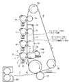
図1は、本発明の実施の形態に係る電子写真プロセスを利用したカラーレーザビームプリンタ、特に電子写真方式を用いたプロセスカートリッジを有するレーザビームプリンタの記録及び転写部の概略断面図である。尚、プロセスカートリッジとは、帯電手段、現像手段、又はクリーニング手段と電子写真感光体ドラムとを一体的にカートリッジ化し、このカートリッジを画像形成装置本体に対して着脱可能とするものである。或は、帯電手段、現像手段、クリーニング手段の少なくとも1つと電子写真感光体ドラムとを一体的にカートリッジ化して画像形成装置本体に着脱可能とするものである。又は少なくとも現像手段と電子写真感光体ドラムとを一体的にカートリッジ化して画像形成装置(レーザビームプリンタ)本体に着脱可能とするものをいう。 FIG. 1 is a schematic sectional view of a recording and transfer unit of a color laser beam printer using an electrophotographic process according to an embodiment of the present invention, particularly a laser beam printer having a process cartridge using an electrophotographic system. The process cartridge is a cartridge in which a charging unit, a developing unit, or a cleaning unit and an electrophotographic photosensitive drum are integrally formed, and the cartridge can be attached to and detached from the image forming apparatus main body. Alternatively, at least one of a charging unit, a developing unit, and a cleaning unit and an electrophotographic photosensitive drum are integrally formed into a cartridge that can be attached to and detached from the main body of the image forming apparatus. Alternatively, it means that at least the developing means and the electrophotographic photosensitive drum are integrated into a cartridge so that the image forming apparatus (laser beam printer) can be attached to and detached from the body.
このカラーレーザビームプリンタは、複数の第一の像担持体である感光体ドラム1(Y,M,C,Bk用に計4個)を有し、順次、第2の像担持体である中間転写ベルト6に連続的に多重転写し、フルカラープリント画像を得る4連ドラム方式(インライン方式)プリンタである。
The color laser beam printer has a plurality of photosensitive drums 1 (four in total for Y, M, C, and Bk) that are a plurality of first image carriers, and in turn an intermediate that is a second image carrier. This is a four-drum type (in-line type) printer that continuously transfers multiple images onto the
感光体ドラム1は、例えば負帯電の有機感光体で、アルミニウム製のドラム基体(不図示)上に感光体層(不図示)を有しており、所定の周速で矢印方向(反時計回り方向)に回転駆動され、その回転過程において接触する帯電ローラ2により負極性の一様な帯電を受ける。帯電手段としての帯電ローラ2は、感光体ドラム1の表面に回転自在に接触し、帯電バイアス電源(不図示)から印加される帯電バイアスによって感光体ドラム1を負帯電の所定電位に均一に帯電する。現像装置は、一成分現像剤としての非磁性のトナーで現像を行う接触一成分現像装置であり、現像容器(トナーカートリッジ)8の開口部に感光体ドラム1と対向配置された時計回り方向に回転自在な現像剤担持体としての現像ローラ9、現像ローラ9に圧接する回転自在な弾性ローラ10、現像ローラ9に当接する弾性を有する規制ブレード(不図示)、現像容器8内のトナーを攪拌する攪拌部材(不図示)を備えている。尚、この規制ブレードは、現像ローラ9と弾性ローラとの圧接部に対して現像ローラ9の回転方向下流側で現像ローラ9に当接している。
The
現像容器8内の攪拌部材で攪拌されたトナーは現像ローラ9の表面に供給される。そして、現像ローラ9の表面に供給されたトナーは現像ローラ9の回転に伴って搬送され、規制ブレードと現像ローラ9の当接部で摩擦により電荷が付与されて、現像ローラ9の表面に薄層化される。この薄層化されたトナーは現像ローラ9の回転によって搬送され、感光体ドラム1との当接部(現像部)にて感光体ドラム1上に形成された静電潜像に付着して顕像化される。尚、現像ローラ9の現像に寄与しなかったトナーは弾性ローラ10で剥ぎ取られる。
The toner stirred by the stirring member in the developing
次に転写部について説明する。 Next, the transfer part will be described.
無端状の中間転写ベルト6が、駆動ローラ6a、テンションローラ6b及び2次転写対向ローラ6cに懸架され、図中矢印の方向に回転している。テンションローラ6bの荷重は、片側2.0kgfのばねで両側からテンションがかけられている。感光体ドラム1は、中間転写ベルト6の移動方向に、直列に各色に対応し4本配置されている。イエロー現像器を有するプロセスユニット(イエロー)内の感光体ドラム1は回転過程で、1次帯電ローラ2により所定の極性及び電位に一様に帯電され、次いで不図示の画像露光手段(カラー原稿画像の色分解、結像露光光学系、画像情報の時系列電気デジタル画素信号に対応して変調されたレーザビームを出力するレーザスキャンによる走査露光系等)による画像露光3を受けることにより目的のカラー画像の第1の色成分像(イエロー成分像)に対応した静電潜像が形成される。次いで、その静電潜像が第1現像器4(イエロー現像器)により第1色であるイエロートナーにより現像される。
An endless
感光体ドラム1上に形成されたイエロー画像は、中間転写ベルト6との1次転写ニップ部へ進入する。この転写ニップ部では、中間転写ベルト6の裏側に1次転写ローラ7を接触当接させている。電圧印加部材には、各ポートで独立にバイアスを印加可能とするため、不図示の1次転写バイアス源を有している。中間転写ベルト6は1色目のポートでまずイエローを転写し、次いで前述した工程を経て、各色に対応する感光体ドラム1より順次マゼンタ、シアン、ブラックの各色を各ポートで多重転写する。そして各感光体ドラム1上に残されたトナーは、各感光体ドラム1に当接されたクリーニングブレードによりクリーニングされ、クリーニングされたトナーは、不図示の廃トナー容器に回収される。
The yellow image formed on the
こうして中間転写ベルト6上で形成された4色フルカラー画像は、次いで2次転写ローラ13により転写材Pに一括転写され、定着装置80によって溶融定着されてカラープリント画像を得る。
The four-color full-color image thus formed on the
一方、モノクロモード時は、前述した1次転写ローラ7(イエロー、マゼンタ、シアン)が図1の点線部7a〜7cで示すように離間する。この結果、中間転写ベルト6は、イエロー、マゼンタ、シアンの感光体ドラム1と離間する。このように離間させる機構では、イエロー、マゼンタ、シアンの1次転写部とブラックの1次転写部は、それぞれITBユニット内で分割されており、カラーユニット11は、14を回転中心として、カム12により、当接離間可能な構成となっている。このカム12は、フルカラーモード時は、矢印12aの方向へ回転してカラーユニット11を持ち上げ、イエロー、マゼンタ、シアンの1次転写部は、感光体ドラム1に当接する。また、モノクロモード時は、このカム12は、矢印12aと反対方向へ回転してカラーユニット11はドラム1と離間する。このため中間転写ベルト6は、カラー画像形成用の感光体ドラム1から離間する。
On the other hand, in the monochrome mode, the primary transfer rollers 7 (yellow, magenta, cyan) described above are separated as indicated by
このような構成をとっているため、通常のフルカラーモード時は、図1に示すように、1次転写ローラ7が中間転写ベルト6を感光体ドラム1方向に押圧し、中間転写ベルト6と感光体ドラム1とを圧接させている。一方、モノクロモード時は、中間転写ベルト6との接触を絶たれたイエロー、マゼンタ、シアンの各プロセスユニット内の感光体ドラム1、現像スリーブ、帯電ローラ2は回転を停止して、ブラックのみ画像形成を行い、モノクロ画像を得る。
With this configuration, in the normal full color mode, as shown in FIG. 1, the primary transfer roller 7 presses the
図3は、本実施の形態に係るプロセスカートリッジの構造を説明する図で、ここでは弾性ローラ10を省略して示している。
FIG. 3 is a view for explaining the structure of the process cartridge according to the present embodiment, in which the
感光体ドラム1の周囲には、帯電ローラ2、現像容器8、クリーニングブレード15が設置されており、帯電ローラ2と現像容器8との間でレーザ光3による露光が行われる。感光体ドラム1は、例えば負帯電の有機感光体で、アルミニウム製のドラム基体(不図示)上に感光体層(不図示)を有しており、所定の周速で矢印方向(反時計回り方向)に回転駆動され、その回転過程において接触する帯電ローラ2により負極性の一様な帯電を受ける。この感光体ドラム1の直径はφ25であり、アルミニウムドラム等の導電性基材上に電荷発生層及び電荷輸送層を順次に積層してなる有機光感光体である。またこの電荷輸送層の1cm2当たりの静電容量が1.5pF以上6.0pF以下である。電流リーク防止や、感光体ドラムの電位安定性の観点から、一般的に使用される電位設定においては、感光体ドラム1の膜厚、即ち電荷輸送層の厚みは5〜20μmが好ましい。本実施の形態における感光体ドラム1の電荷輸送層の厚みは15μmとしている。
A charging
また、この回転駆動系は、前述の図2に示すように、感光体ドラム1側が凸ギヤ101、本体側が凹ギヤ102となっており、本体側の凹ギヤ102が、感光体ドラム1の長手方向へ突き出ることにより、感光体ドラム1側のギヤ101とカップリングするようになっている。このような構成により、カートリッジの交換時やジャム処理時にカートリッジを装置本体から取り出すことを可能とし、ユーザビリティを向上させている。
Further, as shown in FIG. 2, the rotational drive system has a
帯電ローラ2は、φ6の芯金(導電性シャフト)80cの周囲に少なくとも弾性体層を被覆した、φ12、面長230mmの導電性の弾性ローラである。また、この帯電ローラ2は、導電性シャフト80cの外周に、弾性層、誘電層、表層を積層した多層ローラである。この帯電ローラ2は、芯金80cの両端部を不図示の軸受け部材に回転自由に軸受させて感光体ドラム1の軸に並行に配置し、不図示の押圧手段で感光体ドラム1の面に対して長手方向に所定の均一な押圧力(ローラの片側の荷重が4.9N(500gf))で圧接させてあり、感光体ドラム1の回転に従動して回転する。この感光体ドラム1と帯電ローラ2との当接部が帯電部(帯電ニップ部)Nである。
The charging
この帯電ローラ2に帯電バイアス印加電源801から所定の帯電バイアスが印加されることにより、感光体ドラム1の表面が所定の極性及び電位に接触帯電される。本実施の形態では、DC帯電方式であり、帯電バイアス印加電源801から帯電ローラ2に−800Vの直流電圧を印加して、感光体ドラム1の表面を帯電電位(暗部電位)−450Vに接触帯電させている。
By applying a predetermined charging bias to the charging
現像容器8は、感光体ドラム1の表面の静電潜像を現像部Dにおいてネガトナーで反転現像している。9は現像ローラで、感光体ドラム1に近接または接触し、現像材担持体として機能している。この現像ローラ9は、矢印の時計回り方向に所定の周速度にて回転駆動される。この現像ローラ9は、感光体ドラム1と当接幅を持って接触し、この感光体ドラム1の周速(プロセス速度94.2mm/秒)に対して早めの周速(170mm/秒)で回転駆動される。また現像ローラ9は、長時間感光体ドラム1に当接させておくと、その部分が変形して画像不良が発生することから、プリントを実施するときのみ当接する機構を有している。
The developing
この現像ローラ9の表面は、トナー(t)との摺擦確率を高くし、且つトナーの搬送を良好に行うための適度な凹凸を有しており、本実施の形態では、直径16mm、長さ240mm、肉厚4mmのシリコンゴム層上にアクリル・ウレタン系の薄層がコートされて構成されている。この現像ローラ9には、現像バイアス電源201から負極性の現像バイアス−450Vが印加されている。現像ローラ9は、抵抗を1.0e+4〜1.0e+6[Ω]、表面粗さを0.5〜0.9μm、硬度をアスカーC硬度で45°(荷重1kgf)とした。現像ローラ9の抵抗値の測定は、直径30mmのアルミローラ(不図示)と現像ローラ9を当接荷重500gfで長手方向全域に当接させ、このアルミローラを0.5rpsで回転させる。そして、現像ローラ9に−400Vの直流電圧を印加してアース側に10kΩの抵抗を配置する。そして、この抵抗の両端の電圧を測定し、その測定した電圧値から電流値を算出して現像ローラ9の抵抗を算出する。
The surface of the developing roller 9 has an appropriate unevenness for increasing the probability of rubbing with the toner (t) and carrying the toner satisfactorily. In this embodiment, the surface is 16 mm in diameter and long. A silicon rubber layer having a thickness of 240 mm and a thickness of 4 mm is coated with an acrylic / urethane thin layer. A negative development bias of −450 V is applied to the development roller 9 from a development
現像ローラ9には、現像容器8に基端が取り付けられたウレタンゴム等のドクターブレード300が弾圧接触しており、このドクターブレード300により現像ローラ9の表面上のトナーの層厚を一様な所定値0.4mg/cm2としている。この現像ローラ9は感光体ドラム1に対して1.6倍の速度で回転しており、感光体ドラム1上へ現像されるトナー量は、単色べたでは、およそ0.6mg/cm2となる。現像容器8に貯留させた現像剤(トナー)tは、攪拌部材70で攪拌されると共に、その一部が現像ローラ9に供給されてドクターブレード300により現像ローラ9に塗布される。
A
3は潜像形成手段としての不図示の露光手段、例えば半導体レーザ505(図5)から出力されるレーザ光であり、このレーザ光3により感光体ドラム1の帯電処理面が走査露光されることにより、感光体ドラム1の露光部の帯電電位(明部電位)が−150Vに減衰する。こうして暗部電位部との電位コントラストにより、回転する感光体ドラム1の周面に走査露光パターンに対応した画像情報の静電潜像が形成される。
Reference numeral 3 denotes an exposure unit (not shown) as a latent image forming unit, for example, a laser beam output from a semiconductor laser 505 (FIG. 5). The laser beam 3 scans and exposes the charged surface of the
イエロー現像器を有する感光体ドラム1は、回転過程で、1次帯電ローラ2により所定の極性及び電位に一様に帯電処理され、次いで不図示の画像露光手段(カラー原稿画像の色分解、結像露光光学系、画像情報の時系列電気デジタル画素信号に対応して変調されたレーザビームを出力するレーザスキャンによる走査露光系等)による画像露光3を受けることにより、目的のカラー画像の第1の色成分像(イエロー成分像)に対応した静電潜像が形成される。
A
次いで、その静電潜像が第1現像器8(イエロー現像器)により第1色であるイエロートナーにより現像される。こうして感光体ドラム1上に形成されたイエロー画像は、中間転写ベルト6との1次転写ニップ部へ進入する。この転写ニップ部では、中間転写ベルト6の裏側に一次転写ローラ7を接触当接させている。一次転写ローラ7には各ポートで独立にバイアス印加可能とするため、それぞれ1次転写バイアス源を有している。このバイアス電源501(図5)は、D/A変換ポートを備えた定電圧電源502(図5)を有し、それぞれ0〜3KVの範囲の電圧を出力できる。これにより、CPU510(図5)により256段階の出力調整が可能である。また、このバイアス電源501は電流検知回路503(図5)を有しており、0〜15μAの範囲で256段階の精度で電流(転写ローラ7と感光体ドラム1との間の放電電流)を検出でき、その検出した電流値はA/D変換されてCPU510に入力される。
Next, the electrostatic latent image is developed by the first developing device 8 (yellow developing device) with yellow toner as the first color. The yellow image thus formed on the
画像形成中の一次転写ローラ7へのバイアスは、予め決められらた電流値が得られるようプリント動作の前に数段階の電圧値を印加しており、その電圧値に対応して電流検知回路503で電流を検出して最適印加電圧を求める。本実施の形態では、電流設定値を7μAとした。また、その制御実行時、感光体ドラム1の帯電電位は、プリント中と略等しい暗電位VD=−450Vとした。これに基づいて、暗電位部へ流れる電流が7μAとなるように最適電圧を決める。
As the bias to the primary transfer roller 7 during image formation, several levels of voltage values are applied before the printing operation so as to obtain a predetermined current value, and a current detection circuit corresponding to the voltage value. At 503, the current is detected to determine the optimum applied voltage. In the present embodiment, the current setting value is 7 μA. When the control is executed, the charging potential of the
本実施の形態において、暗電位部電流を7μAとした理由は、あまり暗電位部で電流を流しすぎると、再転写量の増加(下流の一次転写部で、上流で一次転写された画像が感光体ドラム1上へ逆に転写してしまう現象)が発生し、また暗電位部電流が小さすぎると、一次転写性自体が低下してしまうためである。各一次転写ローラ7の下流には、不図示の除電針が配置されている。 In the present embodiment, the reason why the dark potential portion current is set to 7 μA is that if the current flows too much in the dark potential portion, the retransfer amount increases (the image that is primarily transferred upstream in the downstream primary transfer portion is exposed to light. This is because if the dark potential portion current is too small, the primary transfer property itself deteriorates. A neutralizing needle (not shown) is disposed downstream of each primary transfer roller 7.
一次転写ローラ7は導電性ローラで、外径6mmのステンレス性軸にNBRとエピクロルヒドリンを混合した発泡ゴムで覆った外径14mmのローラである。 The primary transfer roller 7 is a conductive roller, and is a roller having an outer diameter of 14 mm covered with foamed rubber obtained by mixing NBR and epichlorohydrin on a stainless steel shaft having an outer diameter of 6 mm.
図4は、この導電性ローラの抵抗値を測定する状態を説明する図である。 FIG. 4 is a diagram for explaining a state in which the resistance value of the conductive roller is measured.
測定対象のローラ39を、φ30のアルミシリンダ40に片側4.9N(500gf)で当接させ、30rpmで回転させる。電源43からは50V〜1000Vの電圧がローラ39に印加されている。抵抗値が約1.0e+6[Ω]のローラには50Vを印加し、抵抗値が1.0e+7[Ω]以上のローラには1000Vを印加する。このときに流れる電流は、抵抗42の端子間電圧を電圧計41で測定して求める。
The
このように測定した結果が、抵抗値1.0e+8[Ω]のローラを使用した。ローラ硬度は、AskerCで30度であった。また、ローラの押圧に関しては、4.9N(500gf)のばねをローラの両端に配置させ、中間転写ベルト6を介して感光体ドラム1に押圧した。
A roller having a resistance value of 1.0e + 8 [Ω] was used as a result of such measurement. The roller hardness was 30 degrees in Asker C. Regarding the pressing of the roller, 4.9 N (500 gf) springs were arranged at both ends of the roller and pressed against the
このような条件で、最初のカラーステーション(Y)で、まずイエローの画像を中間転写ベルト6上に一次転写し、次いで前述した工程を経て、各色に対応する感光体ドラム1より順次、マゼンタ、シアン、ブラックの各色を各カラーステーションで多重転写する。こうして中間転写ベルト6上で形成された4色のフルカラー画像は、次いで2次転写ローラ13により、転写材Pに一括転写され、定着装置80によってトナーが溶融定着されカラープリント画像を得る。ここで中間転写ベルト6は、周長670mmであり、長手方向の長さは220mmである。またこの中間転写ベルト6には、ポリイミドの単層ベルトを使用し、その物性値は、厚みが60μm、抵抗値(体積抵抗値)が1.0e+9[Ωcm]である。
Under such conditions, at the first color station (Y), first, a yellow image is primarily transferred onto the
尚、上記抵抗値は、JIS−K6911に準拠し、電極とベルト6表面との良好な接触性を得るために導電性ゴムを電極として使用し、ベルト6の体積抵抗率ρvを50V、30秒の電圧印加条件にて、Advantest社製 R8340超高抵抗計(商標)を用いて測定した結果である。
The resistance value is based on JIS-K6911. In order to obtain good contact between the electrode and the surface of the
本実施の形態において、中間転写ベルト6は、これに限定されるものではないが、例えば、ポリスチレン、スチレン系樹脂(クロロポリスチレン、スチレン−ブタジエン共重合体等)、メタクリル酸メチル樹脂、アクリル酸エチル樹脂、変性アクリル樹脂(シリコーン変性アクリル樹脂、アクリル・ウレタン樹脂等)、塩化ビニル樹脂、フェノール樹脂、エポキシ樹脂、ポリエステル樹脂、ポリエステルポリウレタン樹脂、ポリエチレン、ポリプロピレン、ポリブタジエン、ポリ塩化ビニリデン、ポリウレタン樹脂、シリコーン樹脂、フッ素樹脂、変性ポリフェニレンオキサイド樹脂、ポリイミド樹脂、PES等が挙げられる。これらの1種類或は2種類以上を使用することができる。また被覆層の形成方法は、スプレー塗装、浸漬塗装、静電塗装、押出成形など、任意のものを使用することができる。
In the present embodiment, the
中間転写ベルト6の抵抗値を所望の値に調節するために、必要に応じて弾性層や被覆層に導電剤を添加することができる。この導電剤としては、特に実施の形態に限定されるものではないが、例えば、カーボン、アルミやニッケル等の金属粉末、酸化チタン等の金属酸化物、四級アンモニウム塩含有ポリメタクリル酸メチル、ポリビニルアニリン、ポリビニルピロール、ポリジアセチレン、ポリエチレンイミン、含硼素高分子化合物及びポリピロール等の導電性高分子化合物等が挙げられる。これら1種又は2種以上を使用することができる。
In order to adjust the resistance value of the
図5は、本実施の形態に係るレーザビームプリンタにおいて、感光体ドラム1のカップリング不良を検出するための主要機能構成を説明するブロック図で、前述の図面と共通する部分は同じ記号で示し、それらの説明を省略する。尚、以下説明を簡単にするために、Y,M,C,Bkのそれぞれに対応する一つの感光体ドラム1の場合で説明するが、全ての感光体ドラム1におけるカップリング不良が検出できるように構成されていることはもちろんである。
FIG. 5 is a block diagram illustrating a main functional configuration for detecting a coupling failure of the
500は制御部で、このレーザビームプリンタの動作を制御して、例えば不図示のホストコンピュータなどから入力される印刷データに基づいて印刷を行うための制御や、本実施の形態の特徴である感光体ドラム1のカップリング不良を検出するための処理を実行している。バイアス電源部501は、前述したように一次転写ローラ7にバイアス電圧を印加するためのバイアス電源502と、バイアス電源502による電圧印加時の電流値を検出する電流検知回路503を備えている。504は、このレーザビームプリンタのドアの開閉を検出するためのスイッチである。505は半導体レーザで、制御部500からの画像信号或は制御信号に応じてレーザ光を発光している。506は表示部で、オペレータへのメッセージやエラー表示などを行う。特に後述するようにして感光体ドラム1の回転不良が検出されると、オペレータに対して装置本体のドアを開閉して感光体ドラム1の嵌合を確認するような警告を表示する。なお、これ以外にも、警告用のブザーやLEDなどを備えても良い。
A
次に制御部500について説明する。510はCPUで、ROM511に記憶されているプログラムやデータに従って制御部500による制御処理を実行させている。512はRAMで、CPU510の制御動作時にワークエリアとして使用され、各種データを一時的に保存している。ROM511は、CPU510により実行されるプログラムや、各種設定データのような固定データを記憶している。
Next, the
次に、本発明の実施の形態に係るレーザビームで実行される特徴的な制御処理について説明する。 Next, characteristic control processing executed by the laser beam according to the embodiment of the present invention will be described.
この制御は、電源オフ/オン時、ドアのオープン/クローズ時の前多回転制御時、モノクロモードからカラー印刷モードへの切り替わり時に実施される。これは、感光体ドラム1のカップリング不良は、電源オフ時にユーザがドアを開閉した場合や、或は電源がオンしていても、ユーザがジャム処理やカートリッジ交換を目的として、ドアを開閉する場合に発生する可能性があるためである。またモノクロ印刷モード時には、カラー画像形成用の感光体ドラムを回転させないため、モノクロモードからカラー印刷モードへ移行する際に、再度、カラー用の感光体ドラム1をカップリングさせるときにカップリング不良が発生する可能性があるためである。
This control is performed at the time of switching from the monochrome mode to the color printing mode at the time of power off / on, the front multi-rotation control at the time of opening / closing the door, and the monochrome printing mode. This is because the coupling failure of the
次に、感光体ドラム1のカップリング不良を検知するための処理について説明する。
Next, a process for detecting a coupling failure of the
帯電バイアス801からバイアス電圧が帯電ローラ2に印加され、この帯電ローラ2との接触により感光体ドラム1の表面が所定電位になるようにする。本実施の形態では、−450Vの帯電電位になるようバイアスを印加した。感光体ドラム1の表面が転写部を通過した後、転写ローラ7へ電圧を印加する。この際、その印加電圧値をCPU510でコントロールし、転写ローラ7の一周分の時間に目標とする電流値が得られるよう定電流制御を実行する。
A bias voltage is applied to the charging
図6(A)は、この転写ローラ7への印加電圧の変化を示す図、図6(B)は図6(A)に対応した電流の変化を示している。 6A shows a change in the voltage applied to the transfer roller 7, and FIG. 6B shows a current change corresponding to FIG. 6A.
本実施の形態に係る制御では、最初に500Vを印加し、その時の電流値が目標電流に達していない場合には、10msecごとに50Vずつ段階的に電圧を上昇させる。このとき電流値が(目標電流値±0.5)μA以内になると、その段階的に電圧を上昇させる幅、或は段階的に電圧を降下させる幅を20Vに切り替えるよう制御している。 In the control according to the present embodiment, 500 V is first applied, and when the current value does not reach the target current, the voltage is increased stepwise by 50 V every 10 msec. At this time, when the current value falls within (target current value ± 0.5) μA, the width for increasing the voltage stepwise or the width for decreasing the voltage stepwise is switched to 20V.
従って、カップリング不良が発生している場合は、図7(B)に示すように、電流が流れないために電圧が上昇し続ける。このため図7(A)に示すように、電源出力最大値である3KVまで到達する。尚、目標電流値は予め設定された値で、ここでは8μAとしている。この目標電流値は、これ以上の電流を流すと感光体ドラム1の感光層にメモリ状の履歴が残り、画像形成不良をもたらす電流値としている。そして発生した電圧及び電流値を転写ローラ7の一周分に相当する500msecの間、10msec間隔で50回サンプリングし、その平均電圧値Vavg及び平均電流値Iavg(図6,図7)を求めて、RAM512に格納する。
Therefore, when a coupling failure occurs, the voltage continues to rise because no current flows as shown in FIG. 7B. Therefore, as shown in FIG. 7A, the power supply output value reaches 3 KV which is the maximum value. The target current value is a preset value, and is 8 μA here. The target current value is a current value that causes a memory-like history to remain in the photosensitive layer of the
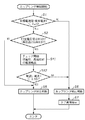
図8は、本実施の形態のレーザビームプリンタにおける感光体ドラム1のカップリング不良の検出処理を説明するフローチャートで、この処理を実行するプログラムはROM511に記憶されており、CPU510の制御の下に実行される。
FIG. 8 is a flowchart for explaining a detection process of a coupling failure of the
この処理が開始されるとステップS1に進み、上述したように、一次転写ローラ7に最初に500Vを印加し、その時に感光体ドラム1に流れる電流値を、電流検知回路503の出力をA/D変換して求める。そしてその求めた電流値が目標電流値に達していない場合には、10msecごとに50Vずつ段階的に電圧を上昇させる。そして、このときに流れる電流値を同様にして求め、図6及び図7に示すようにして、平均電流Iavgと平均電圧Vavgとを算出し、それら平均電圧及び電流値をRAM512に記憶する(これは図9(B)の901で示す区間に相当)。そして目標電流値(ここでは8μA)と平均電流値Iavgとの差分を求める。そして、その差分が所定量(ここでは2μA)以下であるかどうかにより、感光体ドラム1がカップリング不良を起こしているか否か、即ち、カップリング不良が発生しているかどうか判断する。この場合、本願発明者らの検討によれば、目標電流値と平均電流値Iavgとの差分が2μA以内であれば、カップリング不良が発生していないと判断できることが判っている。その理由を以下に説明する。
When this processing is started, the process proceeds to step S1, and as described above, 500 V is first applied to the primary transfer roller 7, and the current value flowing through the
一次転写ローラ7から感光体ドラム1へ流れる電流は放電電流であり、感光体ドラム1が回転していれば、転写ローラ7に印加した電圧値に応じて定常的に電流が流れる。しかしながら、感光体ドラム1の回転が停止している場合には、その放電電流は2〜3μA程度しか流れない。本来、感光体ドラム1の誘電層には、過渡現象と呼ばれる現象で知られているように定常的には電流はほとんど流れない。この過渡現象では、瞬時充電電流から、吸収電流、漏れ電流というように時間とともに推移し、漏れ電流量はほとんどゼロである。しかしながら、電子写真における感光体ドラム1の感光層は光有機半導体であるという特性のため、負帯電感光層はプラス電荷を移動させる働きをもつ。このため、2〜3μA程度の電流が観測される。従って、目標電流値との差分を大きくすると誤検知の可能性が高くなる。このため、このような上記のような設定値とした。
The current that flows from the primary transfer roller 7 to the
一方、ステップS1で、目標電流値と平均電流値Iavgとの差分が2μA以上であればステップS6に進み、カップリングが異常であると判断し、ステップS7でアラームを発生して、ドアを開閉するように指示する。 On the other hand, if the difference between the target current value and the average current value Iavg is 2 μA or more in step S1, the process proceeds to step S6, where it is determined that the coupling is abnormal, and an alarm is generated in step S7 to open / close the door. To instruct.
またステップS1で、目標電流値との差分が2μA以下であればステップS2に進み、平均電圧値Vavgが3KV(最大で圧値)以上であるかどうかを判断する。3.0KV未満であればカップリング不良は発生していないとみなしてステップS5に進む。 In step S1, if the difference from the target current value is 2 μA or less, the process proceeds to step S2, and it is determined whether the average voltage value Vavg is 3 KV (maximum pressure value) or more. If it is less than 3.0 KV, it is determined that no coupling failure has occurred, and the process proceeds to step S5.
一方、3.0KV以上であればステップS3に進み、チェック制御を実行する。以下、このチェック制御を図9(A),(B)を参照して説明する。 On the other hand, if it is 3.0 KV or more, the process proceeds to step S3, and check control is executed. Hereinafter, this check control will be described with reference to FIGS.
図9(A),(B)に示すように、このチェック制御では、まず最初に、902で示すように、一次転写ローラ7の一周分に相当する約500msecの間、レーザ505を駆動して感光体ドラム1上にレーザ光を走査露光して感光体ドラム1の電位を低下させる。本実施の形態では、約−100Vまで低下させた。このときの電位を明電位と称す。このとき、一次転写ローラ7には、ステップS1でホールドした電圧(901で印加された電圧値)が印加されており、この間(902)に流れた電流値が平均化処理される。こうして得られた平均電流値を電流B(Bright電流値)とする。次にレーザ505の駆動を停止してレーザ露光をオフし、一次転写ローラ7の一周分に相当する約500msec間(903)、前回と同様に電流値を検出して平均化処理を実施する。このときの平均電流値を電流D(Dark電流値)とする。
As shown in FIGS. 9A and 9B, in this check control, first, as shown by 902, the
ここで明電位部の電流を最初に検出するのは、この検出精度を上げるためである。暗電位部の電流の検出の後に明電位部の電流の検出を行った場合には、電流量は、(暗電位部)>(明電位部)となるため、時間と共に変化する電流値の変化が過渡電流と同様の変化を示すこととなり検出精度が落ちてしまう。従って、本願発明者らは、この順番は、明電位部の電流を最初に検出し、後で暗電位部を検出する制御とした。 Here, the reason why the current in the bright potential portion is detected first is to increase the detection accuracy. When the current of the light potential portion is detected after the detection of the current of the dark potential portion, the amount of current becomes (dark potential portion)> (light potential portion). Shows the same change as the transient current, and the detection accuracy falls. Therefore, the inventors of the present application set the control to detect the current of the light potential portion first and detect the dark potential portion later.
次にステップS4で、先に求めた電流Bと電流Dが以下の関係式(1)を満たすかどうかでカップリングしているかどうか、即ち、感光体ドラム1が正常に回転しているかどうか判断する。
Next, in step S4, it is determined whether or not the coupling is performed based on whether or not the current B and the current D obtained previously satisfy the following relational expression (1), that is, whether or not the
(電流B−電流D)<0.5 …式(1)
上記式を満たせば、カップリングが正常であると判断する。この場合の閾値は原理的には「0」で良い。しかしながら実際は、計測される電流にはリップルがあるため、平均化処理した後に0.4μA程度の誤差が生じた。従って、この閾値として、このような値(0.5)を設定している。
(Current B−Current D) <0.5 Formula (1)
If the above equation is satisfied, it is determined that the coupling is normal. In principle, the threshold value in this case may be “0”. Actually, however, the measured current has a ripple, and an error of about 0.4 μA occurs after the averaging process. Therefore, such a value (0.5) is set as the threshold value.
以上の制御を実行し、このレーザビームプリンタの寿命100Kpを感光体ドラム1を含むプロセスカートリッジの寿命4KPで割った値に2倍の安全係数を掛けた値に相当する50回分、感光体ドラム1のカップリング不良を故意に発生させ、電源オフ/オン、及び、ドアオープンクローズ時に検出できるか確認した。この結果、全てのカップリング不良を検出できた。そして、このカップリング不良を検知した場合は、ドアの開閉指示をユーザに促すメッセージが表示された。
The above control is executed, and 50 times corresponding to a value obtained by multiplying the lifetime of 100 Kp of the laser beam printer by the lifetime of 4 KP of the process cartridge including the
また、感光体ドラム1を確実にカップリングさせた場合においても50回のテストで誤検知の発生はなかった。
Further, even when the
以上の結果から、転写電流の検知を利用した感光体ドラム1のカップリング不良検出を可能とし、カップリング不良時に発生する現像ローラ9からのトナー飛散を防止することができた。
[参考例]
次に、前述の実施の形態1の変形例である参考例について説明する。尚、この参考例に係るレーザビームプリンタの構成は、前述の実施の形態1と同様であるため、その説明を省略する。
From the above results, it was possible to detect the coupling failure of the
[ Reference example ]
Next, a reference example that is a modification of the above-described first embodiment will be described. Note that the configuration of the laser beam printer according to this reference example is the same as that of the first embodiment described above, and a description thereof will be omitted.
図10は、参考例に係る処理を説明するフローチャートで、この処理を実行するプログラムはROM511に記憶されており、CPU510の制御の下に実行される。尚、この図10において、前述の図8と共通するステップは同じ番号を付して、その説明を省略する。
FIG. 10 is a flowchart for explaining the process according to the reference example . A program for executing this process is stored in the
ステップS2で、印加電圧が3.0KV以上であればステップS11に進み、チェック制御を実行する。以下、この参考例に係るチェック制御を図11(A),(B)を参照して説明する。図11(A)は、レーザビームプリンタの動作をしめす図であり、感光体回転及び中間転写ベルト回転については、ローレベルの信号のときは停止状態でありハイレベルの信号の時は動作状態にあることを示す。また、帯電ローラバイアスについては信号のレベルが負極性である帯電ローラ2のバイアス電圧の値を示し縦軸の上方向がマイナス方向となる。感光体ドラム1及び中間転写ベルト6が停止状態から回転開始して所定時間が経過するまでは帯電ローラ2に印加されるバイアスは0Vであり、その後通常のプリントに使用する−800のバイアス電圧とし、さらにマイナス方向の絶対値が通常のバイアス電圧(−800V)より低い−400Vとし、続いてマイナス方向の絶対値が通常のバイアス電圧(−800V)より高い−900Vとする。
If it is determined in step S2 that the applied voltage is 3.0 KV or higher, the process proceeds to step S11 and check control is executed. Hereinafter, the check control according to this reference example will be described with reference to FIGS. FIG. 11A is a diagram showing the operation of the laser beam printer. Regarding the rotation of the photosensitive member and the intermediate transfer belt, the operation is stopped when the signal is low and the operation is performed when the signal is high. Indicates that there is. As for the charging roller bias, the value of the bias voltage of the charging
図11に示すように、このチェック制御では、まず最初に、一次転写ローラ7の一周分に相当する約500msecの間、帯電ローラ2のバイアス電圧を−400Vに低下させ、帯電電位を一次転写後の電位低下した電位とほぼ同等である約−200V程度にして低電位を形成する(1100)。このとき一次転写ローラ7には、ステップS1(901で示す区間に相当)でホールドした電圧が印加されており、流れた電流値は平均化処理される。この平均化処理方法は前述の実施の形態1と同様である。この場合の平均電流値を電流Lとする。
As shown in FIG. 11, in this check control, first, the bias voltage of the charging
次に帯電ローラ2のバイアス電圧を−900Vに切り替え、感光体ドラム1の帯電電位を高電位−550Vに切り替える。このとき、一次転写ローラ7の一周分に相当する約500msec間、前述の場合と同様に電流値を検出して平均化処理を実施する(1101)。このときの電流値を電流Hとする。その後、通常のプリントに使用する帯電バイアス(−800V)に切り替える。
Next, the bias voltage of the charging
次にステップS12に進み、先に求めた電流Lと電流Hが以下の関係式(2)を満たすかどうかを判定する。 Next, it progresses to step S12 and it is determined whether the electric current L and the electric current H which were calculated | required satisfy | fill the following relational expression (2).
(電流L−電流H)<0.5 …式(2)
この式を満たせば、感光体ドラム1が正常に回転している。即ち、カップリングが正常であると判断する。
(Current L−current H) <0.5 (2)
If this equation is satisfied, the
以上の制御を実施することにより、このレーザビームプリンタの寿命100Kpを、感光体ドラム1を含むプロセスカートリッジの寿命4KPで割った値に2倍の安全係数を掛けた値に相当する50回分、感光体ドラム1のカップリング不良を故意に発生させ、電源オフ/オン、及び、ドアオープンクローズ時に検出できるか確認した。この結果、全てのカップリング不良を検出できた。そして、このカップリング不良を検知した場合は、ドアの開閉指示をユーザに促すメッセージが表示された。
By carrying out the above control, the laser beam printer life of 100 Kp is divided by the life of the process cartridge including the
また、感光体ドラム1を確実にカップリングさせた場合においても50回のテストで誤検知の発生はなかった。
Further, even when the
以上の結果から、転写電流の検知を利用した感光体ドラム1のカップリングの不良検出を可能とし、カップリング不良の発生時に発生する現像ローラ9からのトナーの飛散を防止することができた。
From the above results, it was possible to detect the coupling failure of the
(その他の実施例)
なお本発明は、複数の機器(例えばホストコンピュータ、インターフェース機器、リーダ、プリンタなど)から構成されるシステムに適用しても、一つの機器からなる装置(例えば、複写機、ファクシミリ装置など)に適用してもよい。
(Other examples)
Note that the present invention can be applied to a system (for example, a copier, a facsimile machine, etc.) composed of a single device even if it is applied to a system composed of a plurality of devices (for example, a host computer, interface device, reader, printer, etc.). May be.
また本発明の目的は、前述した実施形態の機能(カメラ側で行われる処理、プリンタ側でわれる各種印刷処理)を実現するソフトウェアのプログラムコードを記録した記憶媒体(または記録媒体)を、システム或は装置に供給し、そのシステム或は装置のコンピュータ(又はCPUやMPU)が記憶媒体に格納されたプログラムコードを読み出し実行することによっても達成される。この場合、記憶媒体から読み出されたプログラムコード自体が前述した実施形態の機能を実現することになり、そのプログラムコードを記憶した記憶媒体は本発明を構成することになる。また、コンピュータが読み出したプログラムコードを実行することにより、前述した実施の形態の機能が実現されるだけでなく、そのプログラムコードの指示に基づき、コンピュータで稼働しているオペレーティングシステム(OS)などが実際の処理の一部又は全部を行い、その処理によって前述した実施の形態の機能が実現される場合も含まれる。 Another object of the present invention is to provide a storage medium (or recording medium) in which a program code of software for realizing the functions of the above-described embodiments (processing performed on the camera side and various printing processes performed on the printer side) is recorded. Is also supplied to the apparatus, and the system or the computer (or CPU or MPU) of the apparatus reads and executes the program code stored in the storage medium. In this case, the program code itself read from the storage medium realizes the functions of the above-described embodiments, and the storage medium storing the program code constitutes the present invention. Further, by executing the program code read by the computer, not only the functions of the above-described embodiments are realized, but also an operating system (OS) running on the computer based on the instruction of the program code. This includes a case where part or all of the actual processing is performed and the functions of the above-described embodiments are realized by the processing.
更に、記憶媒体から読み出されたプログラムコードが、コンピュータに挿入された機能拡張カードやコンピュータに接続された機能拡張ユニットに備わるメモリに書込まれた後、そのプログラムコードの指示に基づき、その機能拡張カードや機能拡張ユニットに備わるCPUなどが実際の処理の一部または全部を行い、その処理によって前述した実施形態の機能が実現される場合も含まれる。例えば、PC上のドライバでこれらの処理を行う場合が、これに相当することは言うまでもない。 Further, after the program code read from the storage medium is written in a memory provided in a function expansion card inserted into the computer or a function expansion unit connected to the computer, the function is determined based on the instruction of the program code. The case where the CPU of the expansion card or the function expansion unit performs part or all of the actual processing and the functions of the above-described embodiments are realized by the processing is also included. For example, it goes without saying that this processing is performed by a driver on a PC.
Claims (4)
前記帯電手段によって前記感光体の表面が所定電位になるように帯電した後に、前記転写ローラに流れる電流が所定の目標電流値になるように前記転写バイアス電源から前記転写ローラに電圧を印加し、前記目標電流値になるように前記転写バイアス電源から前記転写ローラに電圧を印加している間の所定の間に前記電流検出手段が検出した電流値の平均値を平均電流値とし、前記目標電流値と前記平均電流値との差分が所定量より大きい場合は、前記回転駆動手段を介した前記感光体への駆動力の伝達に異常があると判断することを特徴とする画像形成装置。 A photoconductor that carries a toner image ; a rotation driving unit that is fitted to the photoconductor and transmits a driving force from the apparatus main body to the photoconductor to rotate the photoconductor; and a charging unit that charges the photoconductor An exposure means for exposing the photoconductor, a transfer belt for transferring a toner image on the photoconductor to a transfer material, a transfer roller facing the photoconductor via the transfer belt, and a transfer roller An image forming apparatus comprising: a transfer bias power source for applying a voltage; and a current detection unit for detecting a current flowing through the transfer roller,
After charging the surface of the photoconductor to a predetermined potential by the charging unit, a voltage is applied from the transfer bias power source to the transfer roller so that a current flowing through the transfer roller has a predetermined target current value, An average value of the current values detected by the current detection means during a predetermined period while the voltage is applied from the transfer bias power supply to the transfer roller so as to be the target current value is defined as an average current value, and the target current When the difference between the value and the average current value is larger than a predetermined amount, it is determined that there is an abnormality in the transmission of the driving force to the photosensitive member via the rotation driving unit .
前記感光体表面を前記露光手段によって露光させ、前記感光体表面を前記露光手段によって露光させている間の所定の間に前記電流検出手段が検出した電流値の平均値を第1の平均電流値とし、その後、前記露光手段の露光を停止し、前記感光体表面を前記露光手段によって露光させない間の所定の間に前記電流検出手段が検出した電流値の平均値を第2の平均電流値とし、前記第1の平均電流値と前記第2の平均電流値の差分が所定量より大きい場合は、前記回転駆動手段を介した前記感光体への駆動力の伝達に異常があると判断することを特徴とする画像形成装置。The average value of the current values detected by the current detection means during a predetermined period while the photosensitive member surface is exposed by the exposure means and the photosensitive member surface is exposed by the exposure means is a first average current value. Then, the exposure of the exposure means is stopped, and the average value of the current values detected by the current detection means during a predetermined period while the surface of the photoconductor is not exposed by the exposure means is set as the second average current value. When the difference between the first average current value and the second average current value is larger than a predetermined amount, it is determined that there is an abnormality in the transmission of the driving force to the photoconductor via the rotation driving unit. An image forming apparatus.
Priority Applications (1)
| Application Number | Priority Date | Filing Date | Title |
|---|---|---|---|
| JP2003395732A JP4497901B2 (en) | 2003-11-26 | 2003-11-26 | Image forming apparatus |
Applications Claiming Priority (1)
| Application Number | Priority Date | Filing Date | Title |
|---|---|---|---|
| JP2003395732A JP4497901B2 (en) | 2003-11-26 | 2003-11-26 | Image forming apparatus |
Publications (3)
| Publication Number | Publication Date |
|---|---|
| JP2005156972A JP2005156972A (en) | 2005-06-16 |
| JP2005156972A5 JP2005156972A5 (en) | 2007-06-21 |
| JP4497901B2 true JP4497901B2 (en) | 2010-07-07 |
Family
ID=34721424
Family Applications (1)
| Application Number | Title | Priority Date | Filing Date |
|---|---|---|---|
| JP2003395732A Expired - Fee Related JP4497901B2 (en) | 2003-11-26 | 2003-11-26 | Image forming apparatus |
Country Status (1)
| Country | Link |
|---|---|
| JP (1) | JP4497901B2 (en) |
Families Citing this family (3)
| Publication number | Priority date | Publication date | Assignee | Title |
|---|---|---|---|---|
| JP2006293256A (en) * | 2005-03-16 | 2006-10-26 | Ricoh Co Ltd | Image forming apparatus and remote centralized control system |
| JP2007163838A (en) * | 2005-12-14 | 2007-06-28 | Samsung Electronics Co Ltd | Image forming apparatus |
| JP5028855B2 (en) * | 2006-04-27 | 2012-09-19 | 富士ゼロックス株式会社 | Image forming apparatus |
Citations (6)
| Publication number | Priority date | Publication date | Assignee | Title |
|---|---|---|---|---|
| JPH06186867A (en) * | 1992-12-15 | 1994-07-08 | Canon Inc | Image forming device |
| JPH07319296A (en) * | 1994-05-24 | 1995-12-08 | Ricoh Co Ltd | Transfer belt device |
| JP2000194246A (en) * | 1998-12-25 | 2000-07-14 | Canon Inc | Processing cartridge and electrophotographic image forming device |
| JP2002207372A (en) * | 2001-01-04 | 2002-07-26 | Hitachi Ltd | Image forming device |
| JP2002333798A (en) * | 2001-05-10 | 2002-11-22 | Canon Inc | Electrophotographic picture forming apparatus and process cartridge |
| JP2002333811A (en) * | 2001-05-10 | 2002-11-22 | Canon Inc | Electrophotographic imaging device and process cartridge |
-
2003
- 2003-11-26 JP JP2003395732A patent/JP4497901B2/en not_active Expired - Fee Related
Patent Citations (6)
| Publication number | Priority date | Publication date | Assignee | Title |
|---|---|---|---|---|
| JPH06186867A (en) * | 1992-12-15 | 1994-07-08 | Canon Inc | Image forming device |
| JPH07319296A (en) * | 1994-05-24 | 1995-12-08 | Ricoh Co Ltd | Transfer belt device |
| JP2000194246A (en) * | 1998-12-25 | 2000-07-14 | Canon Inc | Processing cartridge and electrophotographic image forming device |
| JP2002207372A (en) * | 2001-01-04 | 2002-07-26 | Hitachi Ltd | Image forming device |
| JP2002333798A (en) * | 2001-05-10 | 2002-11-22 | Canon Inc | Electrophotographic picture forming apparatus and process cartridge |
| JP2002333811A (en) * | 2001-05-10 | 2002-11-22 | Canon Inc | Electrophotographic imaging device and process cartridge |
Also Published As
| Publication number | Publication date |
|---|---|
| JP2005156972A (en) | 2005-06-16 |
Similar Documents
| Publication | Publication Date | Title |
|---|---|---|
| JP4027287B2 (en) | Image forming apparatus | |
| US8135303B2 (en) | Image forming apparatus for preventing contamination of a backside of a recording medium | |
| JP2010008641A (en) | Image forming apparatus | |
| JP5546269B2 (en) | Image forming apparatus | |
| JP2006349967A (en) | Image forming apparatus | |
| JP2011180284A (en) | Image forming apparatus | |
| JP4498339B2 (en) | Image forming apparatus | |
| KR20110131138A (en) | Image forming apparatus | |
| US8180235B2 (en) | Image forming apparatus | |
| JP4497901B2 (en) | Image forming apparatus | |
| US9547251B2 (en) | Image forming apparatus having controllable potential difference | |
| JP2010117636A (en) | Image forming device | |
| JP6335664B2 (en) | Image forming apparatus | |
| JP7027098B2 (en) | Image forming device | |
| JP4949752B2 (en) | Image forming apparatus | |
| JP2009271194A (en) | Image forming apparatus | |
| JP4565055B2 (en) | Image forming apparatus | |
| JP2002365937A (en) | Imaging apparatus | |
| JP2002162795A (en) | Image forming device | |
| US11526104B2 (en) | Image forming apparatus capable of setting transfer voltage and suppressing deterioration of members due to control operation of transfer voltage | |
| JP6580207B2 (en) | Image forming apparatus | |
| JP2006267549A (en) | Image forming apparatus | |
| JP4140211B2 (en) | Image forming apparatus | |
| JP5413658B2 (en) | Image forming apparatus | |
| JP5177473B2 (en) | Image forming apparatus, process cartridge |
Legal Events
| Date | Code | Title | Description |
|---|---|---|---|
| A621 | Written request for application examination |
Free format text: JAPANESE INTERMEDIATE CODE: A621 Effective date: 20061127 |
|
| A521 | Written amendment |
Free format text: JAPANESE INTERMEDIATE CODE: A523 Effective date: 20070508 |
|
| A977 | Report on retrieval |
Free format text: JAPANESE INTERMEDIATE CODE: A971007 Effective date: 20091120 |
|
| A131 | Notification of reasons for refusal |
Free format text: JAPANESE INTERMEDIATE CODE: A131 Effective date: 20091218 |
|
| A521 | Written amendment |
Free format text: JAPANESE INTERMEDIATE CODE: A523 Effective date: 20100216 |
|
| TRDD | Decision of grant or rejection written | ||
| A01 | Written decision to grant a patent or to grant a registration (utility model) |
Free format text: JAPANESE INTERMEDIATE CODE: A01 Effective date: 20100326 |
|
| A01 | Written decision to grant a patent or to grant a registration (utility model) |
Free format text: JAPANESE INTERMEDIATE CODE: A01 |
|
| A61 | First payment of annual fees (during grant procedure) |
Free format text: JAPANESE INTERMEDIATE CODE: A61 Effective date: 20100413 |
|
| FPAY | Renewal fee payment (event date is renewal date of database) |
Free format text: PAYMENT UNTIL: 20130423 Year of fee payment: 3 |
|
| R150 | Certificate of patent or registration of utility model |
Ref document number: 4497901 Country of ref document: JP Free format text: JAPANESE INTERMEDIATE CODE: R150 Free format text: JAPANESE INTERMEDIATE CODE: R150 |
|
| FPAY | Renewal fee payment (event date is renewal date of database) |
Free format text: PAYMENT UNTIL: 20130423 Year of fee payment: 3 |
|
| FPAY | Renewal fee payment (event date is renewal date of database) |
Free format text: PAYMENT UNTIL: 20140423 Year of fee payment: 4 |
|
| LAPS | Cancellation because of no payment of annual fees |