JP4495081B2 - Brake system inspection device for motorcycle and brake system inspection method - Google Patents
Brake system inspection device for motorcycle and brake system inspection method Download PDFInfo
- Publication number
- JP4495081B2 JP4495081B2 JP2005377134A JP2005377134A JP4495081B2 JP 4495081 B2 JP4495081 B2 JP 4495081B2 JP 2005377134 A JP2005377134 A JP 2005377134A JP 2005377134 A JP2005377134 A JP 2005377134A JP 4495081 B2 JP4495081 B2 JP 4495081B2
- Authority
- JP
- Japan
- Prior art keywords
- brake
- rear wheel
- front wheel
- support roller
- wheeled vehicle
- Prior art date
- Legal status (The legal status is an assumption and is not a legal conclusion. Google has not performed a legal analysis and makes no representation as to the accuracy of the status listed.)
- Expired - Fee Related
Links
Images


Classifications
-
- B—PERFORMING OPERATIONS; TRANSPORTING
- B60—VEHICLES IN GENERAL
- B60T—VEHICLE BRAKE CONTROL SYSTEMS OR PARTS THEREOF; BRAKE CONTROL SYSTEMS OR PARTS THEREOF, IN GENERAL; ARRANGEMENT OF BRAKING ELEMENTS ON VEHICLES IN GENERAL; PORTABLE DEVICES FOR PREVENTING UNWANTED MOVEMENT OF VEHICLES; VEHICLE MODIFICATIONS TO FACILITATE COOLING OF BRAKES
- B60T8/00—Arrangements for adjusting wheel-braking force to meet varying vehicular or ground-surface conditions, e.g. limiting or varying distribution of braking force
- B60T8/17—Using electrical or electronic regulation means to control braking
- B60T8/1701—Braking or traction control means specially adapted for particular types of vehicles
- B60T8/1706—Braking or traction control means specially adapted for particular types of vehicles for single-track vehicles, e.g. motorcycles
-
- B—PERFORMING OPERATIONS; TRANSPORTING
- B60—VEHICLES IN GENERAL
- B60T—VEHICLE BRAKE CONTROL SYSTEMS OR PARTS THEREOF; BRAKE CONTROL SYSTEMS OR PARTS THEREOF, IN GENERAL; ARRANGEMENT OF BRAKING ELEMENTS ON VEHICLES IN GENERAL; PORTABLE DEVICES FOR PREVENTING UNWANTED MOVEMENT OF VEHICLES; VEHICLE MODIFICATIONS TO FACILITATE COOLING OF BRAKES
- B60T8/00—Arrangements for adjusting wheel-braking force to meet varying vehicular or ground-surface conditions, e.g. limiting or varying distribution of braking force
- B60T8/32—Arrangements for adjusting wheel-braking force to meet varying vehicular or ground-surface conditions, e.g. limiting or varying distribution of braking force responsive to a speed condition, e.g. acceleration or deceleration
- B60T8/88—Arrangements for adjusting wheel-braking force to meet varying vehicular or ground-surface conditions, e.g. limiting or varying distribution of braking force responsive to a speed condition, e.g. acceleration or deceleration with failure responsive means, i.e. means for detecting and indicating faulty operation of the speed responsive control means
- B60T8/885—Arrangements for adjusting wheel-braking force to meet varying vehicular or ground-surface conditions, e.g. limiting or varying distribution of braking force responsive to a speed condition, e.g. acceleration or deceleration with failure responsive means, i.e. means for detecting and indicating faulty operation of the speed responsive control means using electrical circuitry
-
- G—PHYSICS
- G01—MEASURING; TESTING
- G01L—MEASURING FORCE, STRESS, TORQUE, WORK, MECHANICAL POWER, MECHANICAL EFFICIENCY, OR FLUID PRESSURE
- G01L5/00—Apparatus for, or methods of, measuring force, work, mechanical power, or torque, specially adapted for specific purposes
- G01L5/28—Apparatus for, or methods of, measuring force, work, mechanical power, or torque, specially adapted for specific purposes for testing brakes
- G01L5/282—Apparatus for, or methods of, measuring force, work, mechanical power, or torque, specially adapted for specific purposes for testing brakes the vehicle wheels cooperating with rotatable rolls
-
- G—PHYSICS
- G01—MEASURING; TESTING
- G01L—MEASURING FORCE, STRESS, TORQUE, WORK, MECHANICAL POWER, MECHANICAL EFFICIENCY, OR FLUID PRESSURE
- G01L5/00—Apparatus for, or methods of, measuring force, work, mechanical power, or torque, specially adapted for specific purposes
- G01L5/28—Apparatus for, or methods of, measuring force, work, mechanical power, or torque, specially adapted for specific purposes for testing brakes
- G01L5/286—Measuring deceleration
-
- B—PERFORMING OPERATIONS; TRANSPORTING
- B60—VEHICLES IN GENERAL
- B60T—VEHICLE BRAKE CONTROL SYSTEMS OR PARTS THEREOF; BRAKE CONTROL SYSTEMS OR PARTS THEREOF, IN GENERAL; ARRANGEMENT OF BRAKING ELEMENTS ON VEHICLES IN GENERAL; PORTABLE DEVICES FOR PREVENTING UNWANTED MOVEMENT OF VEHICLES; VEHICLE MODIFICATIONS TO FACILITATE COOLING OF BRAKES
- B60T2270/00—Further aspects of brake control systems not otherwise provided for
- B60T2270/40—Failsafe aspects of brake control systems
- B60T2270/406—Test-mode; Self-diagnosis
Description
本発明は、二輪自動車に設けられたアンチロックブレーキシステムや、アンチロックブレーキシステムを備える前後輪連動ブレーキシステムの検査を行う検査装置及び検査方法に関する。 The present invention relates to an inspection device and an inspection method for inspecting an antilock brake system provided in a two-wheeled vehicle and a front and rear wheel interlocking brake system including the antilock brake system.
従来、二輪自動車のアンチロックブレーキシステム(以下ABSと言う)及び前後輪連動ブレーキシステム(以下CBSと言う)の作動を検査する装置が知られている(例えば、特許文献1参照)。 2. Description of the Related Art Conventionally, an apparatus for inspecting the operation of an antilock brake system (hereinafter referred to as ABS) and a front and rear wheel interlocking brake system (hereinafter referred to as CBS) of a two-wheeled vehicle is known (for example, see Patent Document 1).
この検査装置は、前輪を着座させて支持する一対の支持ローラ(前輪支持ローラ)と、後輪を着座させて支持する一対の支持ローラ(後輪支持ローラ)とを備え、一方の前輪支持ローラと一方の後輪支持ローラとは、互いに同期して回転するように連結手段により連結されている。なお、各ローラはその表面が低摩擦材料によって形成されている。また、他方の前輪支持ローラ及び他方の後輪支持ローラには、夫々のローラの回転速度を検出する回転速度検出手段が連結して設けられている。更に、一方の後輪支持ローラにはクラッチを介して駆動モータが連結されている。 This inspection apparatus includes a pair of support rollers (front wheel support rollers) for seating and supporting a front wheel, and a pair of support rollers (rear wheel support rollers) for seating and supporting a rear wheel, and one front wheel support roller And the one rear wheel support roller are connected by a connecting means so as to rotate in synchronization with each other. Each roller has a surface made of a low friction material. The other front wheel support roller and the other rear wheel support roller are provided with a rotation speed detecting means for detecting the rotation speed of each roller. Further, a driving motor is connected to one of the rear wheel support rollers via a clutch.
このように構成された検査装置において、二輪自動車のABSの検査を行なうときには、先ず、テスト車両の前輪及び後輪を夫々一対の前輪支持ローラ及び一対の後輪支持ローラに載置し、前記駆動モータにより後輪支持ローラを回転させる。これにより、後輪を介して後輪支持ローラが共に回転し、さらにこの回転が一方の前輪支持ローラを介して前輪及び他方の前輪支持ローラに伝達されるので、全ローラーが同期回転することになる。 In the inspection apparatus configured as described above, when inspecting the ABS of a two-wheeled vehicle, first, the front wheels and the rear wheels of the test vehicle are respectively placed on a pair of front wheel support rollers and a pair of rear wheel support rollers, and the drive The rear wheel support roller is rotated by a motor. As a result, the rear wheel support rollers rotate together via the rear wheels, and this rotation is transmitted to the front wheels and the other front wheel support rollers via one front wheel support roller, so that all the rollers rotate synchronously. Become.
続いて、前記回転速度検出手段から得られるローラの回転速度が所定の速度となったとき、前記クラッチがOFF状態となって一方の後輪支持ローラが駆動モータが切り離され、この状態で作業者がブレーキを全入力する。そして、前記クラッチにより駆動モータの駆動力から切り離された各ローラは慣性で回転を続行する一方、ブレーキ入力による減速で徐々に各ローラの回転速度が低下する。このとき、各ローラの表面が低摩擦材料によって形成されていることから二輪自動車の車輪と各ローラとの間にスリップが生じるので、ABSが作動してポンピングブレーキが行われる。その後、ブレーキの作動によって各ローラが停止し、その停止時間と予め実走測定で定められた値とを比較することで、ABSの性能の良否が判定される。 Subsequently, when the rotation speed of the roller obtained from the rotation speed detection means reaches a predetermined speed, the clutch is turned off and one of the rear wheel support rollers is disconnected from the driving motor. Inputs all brakes. Each roller separated from the driving force of the drive motor by the clutch continues to rotate with inertia, while the rotational speed of each roller gradually decreases due to deceleration by brake input. At this time, since the surface of each roller is formed of a low-friction material, slip occurs between the wheels of the two-wheeled vehicle and each roller, so that the ABS operates and pumping brake is performed. Thereafter, each roller is stopped by the operation of the brake, and whether the performance of the ABS is good or not is determined by comparing the stop time with a value determined in advance by actual running measurement.
また、前記従来の検査装置により二輪自動車のCBSの検査を行なう場合にも、ABSの検査時と同様に、一方のブレーキ(例えば後輪ブレーキ)を入力して他方のブレーキ(前輪ブレーキ)を連動させ、各ローラの停止時間と予め実走測定で定められた値とを比較することで、CBSの性能の良否が判定される。 Also, when the CBS inspection of a two-wheeled vehicle is performed by the conventional inspection device, as in the ABS inspection, one brake (for example, the rear wheel brake) is input and the other brake (the front wheel brake) is interlocked. Then, the quality of the CBS is judged to be good or bad by comparing the stop time of each roller with a value determined in advance by actual running measurement.
しかし、前記従来の検査装置によるABS検査では、ブレーキ入力した後に各支持ローラの回転が停止しなければ判定結果が得られず、検査時間が比較的長くかかる不都合がある。しかも、CBSの作動確認が作業者の体感によって行なわれるので、作業者に熟練が要求され、高い検査精度が望めない不都合がある。 However, in the ABS inspection by the conventional inspection apparatus, the determination result cannot be obtained unless the rotation of each support roller stops after the brake is input, and there is a disadvantage that the inspection time is relatively long. In addition, since the operation confirmation of the CBS is performed by the operator's experience, the operator is required to be skilled, and there is a disadvantage that high inspection accuracy cannot be expected.
そこで、ABSの作動時におけるブレーキのON・OFFの繰り返しに伴う車輪の回転速度の増減を測定し、この測定データに基づいて波形を求め、その波形の一部が、所定の経過時間内に定められた所定範囲内にあるか否かを判定することで、ABS及びCBSの良否判定を行うものが提案されている(例えば、特許文献2参照)。これによれば、ブレーキ入力から車輪が停止するまでの経過時間を採取することなく、ブレーキシステムの検査が行えるので、検査時間を大幅に短縮することができる。 Therefore, the increase / decrease in the rotational speed of the wheel accompanying the repeated ON / OFF of the brake during the operation of the ABS is measured, and a waveform is obtained based on this measurement data. A part of the waveform is determined within a predetermined elapsed time. It has been proposed to determine whether or not ABS and CBS are acceptable by determining whether they are within a predetermined range (see, for example, Patent Document 2). According to this, since the brake system can be inspected without collecting the elapsed time from the brake input to the stop of the wheel, the inspection time can be greatly shortened.
しかし、このものにおいても、一方の前輪支持ローラと一方の後輪支持ローラとは、連結手段により互いに同期して回転するように連結されている。これによって、特にCBSの検査において、前輪と後輪との回転速度の増減を測定しても、両者の回転速度の増減が、CBSの作動によるものであるのか、連結手段を介して一方の車輪から他方の車輪に制動力が伝達されたものであるのかが明確でない不都合がある。 However, also in this case, one front wheel support roller and one rear wheel support roller are connected so as to rotate in synchronization with each other by a connecting means. As a result, even when the increase / decrease in the rotational speed of the front wheel and the rear wheel is measured particularly in the inspection of the CBS, whether the increase / decrease in the rotational speed of the both is due to the operation of the CBS, one of the wheels via the connecting means Therefore, there is a disadvantage that it is not clear whether the braking force is transmitted to the other wheel.
即ち、CBSが搭載された二輪自動車によっては、後輪ブレーキと前輪ブレーキとの連動時の制動力が異なるように配分されている場合がある。このような二輪自動車において、例えば、後輪ブレーキの全入力時にCBSによる前輪ブレーキの作動が後輪ブレーキよりも極めて小さな制動力に設定されていると、前輪の回転速度の増減が前輪ブレーキによる実際の作動によるものではなく、連結手段を通じて前輪に伝達された後輪の制動力の影響によるものであることも考えられる。そして、このような状況で採取される測定データに基づいて良否判定を行うと、前輪ブレーキが作動していないにもかかわらず、CBSによる連動が正常に行われていると判定されるおそれがあり、検査精度が低くなる不都合がある。
かかる不都合を解消して、本発明は、二輪自動車の各検査にかかる時間を短縮して二輪自動車の検査を効率よく行えるだけでなく、検査精度を飛躍的に向上させることができる二輪自動車のブレーキシステム検査装置及びブレーキシステム検査方法を提供することを目的とする。 The present invention eliminates such inconveniences, and the present invention shortens the time required for each inspection of a two-wheeled vehicle to efficiently inspect the two-wheeled vehicle, and also can greatly improve the inspection accuracy. A system inspection device and a brake system inspection method are provided.
かかる目的を達成するために、本発明は、二輪自動車に搭載されたアンチロックブレーキシステム及び前後輪連動ブレーキシステムの作動を検査する二輪自動車のブレーキシステム検査装置であって、二輪自動車の前輪を支持すべく互いに軸線が平行に配置された回転自在の一対の支持ローラと、二輪自動車の後輪を支持すべく互いに軸線が平行に配置された回転自在の一対の支持ローラと、前輪を支持する少なくとも一方の支持ローラと後輪を支持する少なくとも一方の支持ローラとを連結して同期回転させる連結手段と、二輪自動車の各々の車輪にアンチロックブレーキシステムが作動するとき、該車輪を支持する支持ローラを介して該車輪の回転速度を測定する第1測定手段と、前輪に備えるブレーキ作動部と後輪に備えるブレーキ作動部とのうち少なくとも一方のブレーキ作動部の少なくとも一部の温度を測定する第2測定手段と、第1測定手段の測定データに基づく第1の良否判定要素と第2測定手段の測定データに基づき該第1の良否判定要素がブレーキ作動部の作動によるものか否かを確認するための第2の良否判定要素とを用いてブレーキシステムの良否を判定する判定手段とを備えることを特徴とする。 In order to achieve this object, the present invention is a brake system inspection device for a two-wheeled vehicle that inspects the operation of an anti-lock brake system and a front-rear wheel-linked brake system mounted on the two-wheeled vehicle, and supports the front wheels of the two-wheeled vehicle. A pair of rotatable support rollers whose axes are arranged parallel to each other, a pair of rotatable support rollers whose axes are arranged parallel to each other to support the rear wheels of the two-wheeled vehicle, and at least a front wheel A connecting means for connecting and rotating one supporting roller and at least one supporting roller for supporting the rear wheel synchronously; and a supporting roller for supporting the wheel when the anti-lock brake system is operated on each wheel of the two-wheeled vehicle. First measuring means for measuring the rotational speed of the wheel via a brake, a brake operating part provided for the front wheel, and a brake action provided for the rear wheel Second measuring means for measuring the temperature of at least a part of at least one of the brake operating parts, a first pass / fail judgment element based on the measurement data of the first measuring means, and the measurement data of the second measuring means. characterized in that Dzu-out first quality determination element comprises a determination means for determining acceptability of a brake system using a second quality determination element for confirming whether or not by the operation of the brake actuating unit And
また、本発明は、二輪自動車に搭載されたアンチロックブレーキシステム及び前後輪連動ブレーキシステムの作動を検査する二輪自動車のブレーキシステム検査方法であって、一対の前輪支持ローラに支持された二輪自動車の前輪を回転させると共に、前輪支持ローラと同期回転する一対の後輪支持ローラに支持された二輪自動車の後輪を回転させて、一方の車輪のブレーキを全入力することによりアンチロックブレーキシステム及び前後輪連動ブレーキシステムを作動させるブレーキ入力工程と、該ブレーキ入力工程における前輪の回転速度と後輪の回転速度とを夫々の支持ローラを介して測定する第1測定工程と、該ブレーキ入力工程における前輪に備えるブレーキ作動部と後輪に備えるブレーキ作動部とのうち少なくとも一方のブレーキ作動部の少なくとも一部の温度を測定する第2測定工程と、第1測定手段の測定データに基づく第1の良否判定要素と第2測定手段の測定データに基づき該第1の良否判定要素がブレーキ作動部の作動によるものか否かを確認するための第2の良否判定要素とを用いてブレーキシステムの良否を判定する判定工程とを備えることを特徴とする。 The present invention also relates to a two-wheeled vehicle brake system inspection method for inspecting the operation of an anti-lock brake system and a front-rear wheel interlocking brake system mounted on a two-wheeled vehicle, the two-wheeled vehicle supported by a pair of front wheel support rollers. Anti-lock brake system and front and rear by rotating front wheels and rotating rear wheels of two-wheeled vehicle supported by a pair of rear wheel support rollers rotating synchronously with front wheel support rollers A brake input step for operating the wheel-linked brake system, a first measurement step for measuring the rotational speed of the front wheel and the rotational speed of the rear wheel in the brake input step via respective support rollers, and the front wheel in the brake input step At least one of the brake operating part provided for the rear wheel and the brake operating part provided for the rear wheel A second measuring step of measuring at least part of the temperature of the working unit, based-out first quality determination on the measurement data of the first quality determination element and the second measuring means based on the measurement data of the first measuring means And a determination step of determining whether or not the brake system is good by using a second good / bad determination element for confirming whether or not the element is due to the operation of the brake operating unit .
本発明によって二輪自動車のアンチロックブレーキシステム(ABS)及び前後輪連動ブレーキシステム(CBS)の作動を検査するときには、先ず、前輪と後輪とを、夫々に対応する一対の支持ローラに着座させる。次いで、二輪自動車の検査対象となるABSが作動する車輪(前輪又は後輪)のブレーキを入力してABSを作動させる。具体的には、例えば、作業者が前記支持ローラ上で二輪自動車のエンジンを駆動し、所定の検査開始速度になったときに二輪自動車のギヤをニュートラルにしてブレーキを全入力する(ブレーキ入力工程)。これによって、車輪は急ブレーキ状態となるので、車輪とローラとの間にスリップ現象が発生しABSが作動を開始する。このとき、二輪自動車の検査対象となるABSが作動する一方の車輪のブレーキが全入力されたことにより、二輪自動車の検査対象となるCBSが作動する他方の車輪のブレーキが自動的に入力される。そして、両車輪のABSが作動を開始する。 When inspecting the operation of the anti-lock brake system (ABS) and the front and rear wheel interlocking brake system (CBS) of a two-wheeled vehicle according to the present invention, first, the front wheels and the rear wheels are seated on a pair of corresponding support rollers. Next, the brake of the wheel (front wheel or rear wheel) on which the ABS to be inspected of the two-wheeled vehicle is operated is input to operate the ABS. Specifically, for example, an operator drives an engine of a two-wheeled vehicle on the support roller, and when a predetermined inspection start speed is reached, the gear of the two-wheeled vehicle is set to neutral and a brake is fully input (brake input process) ). As a result, the wheel is suddenly braked, so that a slip phenomenon occurs between the wheel and the roller, and the ABS starts operating. At this time, when all the brakes of the one wheel on which the ABS to be inspected for the two-wheeled vehicle operates are input, the brakes on the other wheel on which the CBS to be inspected for the two-wheeled vehicle operates are automatically input. . Then, the ABS of both wheels starts to operate.
前輪ABSと後輪ABSとが共に作動することによって、前輪と後輪との夫々においてブレーキのON・OFFが繰り返されるので、それに応じて両車輪の回転速度が増減し、両車輪の回転挙動が伝達された前輪支持ローラの回転速度と後輪支持ローラの回転速度とが第1測定手段により測定される(第1測定工程)。 When the front wheel ABS and the rear wheel ABS are operated together, the brake is repeatedly turned on and off for each of the front and rear wheels. Accordingly, the rotational speeds of both wheels increase and decrease accordingly, and the rotational behavior of both wheels The transmitted rotation speed of the front wheel support roller and the rotation speed of the rear wheel support roller are measured by the first measuring means (first measurement step).
そして、該第1測定手段から得られた測定データに基づく第1の良否判定要素、例えば具体的には、該第1測定手段から得られた測定値に基づいて演算された車輪の回転速度の変化(例えば減速度或いは加速度の増減)に伴う波形を求め、波形の一部が所定の経過時間内に定められた所定範囲内にあるか否かを前記判定手段によって判定する。このように、第1測定手段から得られた測定データに基づく第1の良否判定要素を、前記判定手段による判定に用いることで、ブレーキ入力から車輪が停止するまでの経過時間を採取することなく、両輪のABSの良否を判定することができる。また、第1の良否判定要素が前輪ブレーキに対する後輪ブレーキの利き具合を示すものであるので、一方の車輪のブレーキに対して他方の車輪のブレーキが過剰に作動しているか、或いは一方の車輪のブレーキに対して他方の車輪のブレーキの作動が不十分であるかが確認でき、ブレーキ入力から車輪が停止するまでの経過時間を採取することなく、CBSの良否を判定することができる。 Then, a first pass / fail judgment element based on the measurement data obtained from the first measurement means, for example, specifically, the rotational speed of the wheel calculated based on the measurement value obtained from the first measurement means. A waveform associated with a change (for example, deceleration or acceleration increase / decrease) is obtained, and it is determined by the determining means whether a part of the waveform is within a predetermined range determined within a predetermined elapsed time. Thus, by using the first pass / fail determination element based on the measurement data obtained from the first measurement means for the determination by the determination means, it is possible to collect the elapsed time from the brake input to the stop of the wheel. The quality of the ABS of both wheels can be determined. Further, since the first pass / fail judgment element indicates the degree of use of the rear wheel brake with respect to the front wheel brake, the brake of the other wheel is excessively operated relative to the brake of one wheel, or one wheel It can be confirmed whether the brake of the other wheel is insufficiently operated with respect to the other brake, and the quality of the CBS can be determined without collecting the elapsed time from the brake input until the wheel stops.
更に、夫々の車輪の支持ローラが連結手段により同期回転されていると、一方の車輪のブレーキが全入力されたときの制動力が連結手段を介して他方の車輪に影響し、CBSが作動せず、他方の車輪のブレーキが自動的に入力されなくても、他方の車輪の回転速度が低下する場合が考えられる。この場合には、第1測定手段から得られた測定データに基づく第1の良否判定要素だけではCBSの良否の判定精度が低下するおそれがある。 Further, when the support rollers of the respective wheels are rotated synchronously by the connecting means, the braking force when the brakes of one wheel are fully input affects the other wheel via the connecting means, and the CBS is activated. However, even if the brake of the other wheel is not automatically input, the rotation speed of the other wheel may be reduced. In this case, there is a possibility that the accuracy of the CBS determination is lowered only by the first quality determination element based on the measurement data obtained from the first measurement means.
そこで、本発明においては、前輪に備えるブレーキ作動部と後輪に備えるブレーキ作動部とのうち少なくとも一方、即ち、二輪自動車の検査対象となるCBSが作動する他方の車輪のブレーキ作動部の少なくとも一部の温度が前記第2測定手段により測定される(第2測定工程)。そして、該第2測定手段から得られた測定データに基づく第2の良否判定要素、例えば具体的には、該第2測定手段から得られた測定値に基づいてブレーキ作動部の温度変化(差分)を求め、この温度変化が十分に生じているか否かを前記判定手段によって判定する。 Therefore, in the present invention, at least one of the brake operation unit provided on the front wheel and the brake operation unit provided on the rear wheel, that is, at least one brake operation unit of the other wheel on which the CBS to be inspected of the two-wheeled vehicle operates. The temperature of the part is measured by the second measuring means (second measuring step). Then, the second pass / fail judgment element based on the measurement data obtained from the second measurement means, for example, specifically, the temperature change (difference of the brake operating part based on the measurement value obtained from the second measurement means). ) Is determined, and it is determined by the determination means whether or not this temperature change has occurred sufficiently.
このように、本発明によれば、第1測定手段の測定データに基づく第1の良否判定要素と第2測定手段の測定データに基づく第2の良否判定要素とからブレーキシステムの良否を判定するので、検査時間を短縮することができるだけなく、検査精度を飛躍的に向上させることができる。 Thus, according to the present invention, the quality of the brake system is determined from the first quality determination element based on the measurement data of the first measurement means and the second quality determination element based on the measurement data of the second measurement means. Therefore, the inspection time can be shortened and the inspection accuracy can be greatly improved.
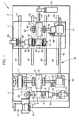
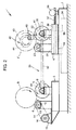
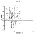
本発明の一実施形態を図面に基づいて説明する。図1は本実施形態の装置構成を示す説明的平面図、図2は図1に示す装置の要部を示す説明的側面図、図3は本実施形態の検査手段を模式的に示すブロック図、図4及び図5は判定手段において用いられる波形を示す線図である。 An embodiment of the present invention will be described with reference to the drawings. FIG. 1 is an explanatory plan view showing the apparatus configuration of this embodiment, FIG. 2 is an explanatory side view showing the main part of the apparatus shown in FIG. 1, and FIG. 3 is a block diagram schematically showing the inspection means of this embodiment. 4 and 5 are diagrams showing waveforms used in the determination means.
図1及び図2において、1は本実施形態の二輪自動車の検査装置1であり、2はベース、3は該ベース2上に設けられて二輪自動車(図示せず)の後輪R側に設けられた後輪用機台、4はその前輪F側に設けられた前輪用機台である。 1 and 2, 1 is a two-wheeled vehicle inspection apparatus 1 according to the present embodiment, 2 is a base, 3 is provided on the base 2, and is provided on the rear wheel R side of the two-wheeled vehicle (not shown). The rear wheel stand 4 is a front wheel stand provided on the front wheel F side.
図1に示すように、後輪用機台3は、二輪自動車の後輪Rを着座支持する一対の後輪支持ローラ5、6を備えている。後輪Rの前側に位置する第1の後輪支持ローラ5は、その回転軸7が一対の軸受け8を介して回転自在に支持されている。後輪Rの後側に位置する第2の後輪支持ローラ6は、その回転軸9が第1の後輪支持ローラ5の回転軸7と平行に、一対の軸受け10を介して回転自在に支持されている。第1の後輪支持ローラ5は、第2の後輪支持ローラ6よりも大径に形成されており、これによって、第1の後輪支持ローラ5の回転慣性力が第2の後輪支持ローラ6よりも大きく設定されている。
As shown in FIG. 1, the rear wheel base 3 includes a pair of rear
第1の後輪支持ローラ5と第2の後輪支持ローラ6とは所定間隔を存して並設され、更に、図2に示すように、第2の後輪支持ローラ6は、後輪Rに接する位置が第1の後輪支持ローラ5と同一の高さとなるように前記軸受け10により支持されている。
The first rear
図1に示すように、第1の後輪支持ローラ5の回転軸7の一方端には電磁ブレーキ11が連結されており、該電磁ブレーキ11の作動により第1の後輪支持ローラ5に掛かる負荷の調整が可能となっている。
As shown in FIG. 1, an
第2の後輪支持ローラ6の回転軸9の一端部にはクラッチ12を介してプーリ13が設けられている。該プーリ13はベルト14を連動部材としてベース2上に設けられたスタータ作動用モータ15のプーリ16に従動する。クラッチ12がONとされたときには、プーリ13が回転軸9に連結され、スタータ作動用モータ15による第2の後輪支持ローラ6の駆動が可能となる。
A
また、第2の後輪支持ローラ6の回転軸9の他端部には、クラッチ17を介してモータ18が連結されている。クラッチ17がONとされたときには、回転軸9とモータ18の駆動軸19とが接続され、モータ18による第2の後輪支持ローラ6の駆動が可能となる。
Further, a
更に、第2の後輪支持ローラ6の回転軸9の一端部には、回転軸9の回転速度を測定する第1ロータリーエンコーダ20が設けられ、回転軸9の他端部には、クラッチ17とモータ18との間に位置して回転軸9の回転トルクを測定する第1トルクメータ21が設けられている。後述するが、第1トルクメータ21は制動力の検査時に使用され、第1ロータリーエンコーダ20は、アンチロックブレーキシステム(ABS)及び前後輪連動ブレーキシステム(CBS)の検査時に使用される。
Furthermore, a first
前輪用機台4は、二輪自動車の前輪Fを着座支持する一対の前輪支持ローラ22、23を備えている。前輪Fの前側に位置する第1の前輪支持ローラ22は、その回転軸24が一対の軸受け25を介して回転自在に支持されている。前輪Fの後側に位置する第2の前輪支持ローラ23は、その回転軸26が第1の前輪支持ローラ22の回転軸24と平行に、一対の軸受け27を介して回転自在に支持されている。第1の前輪支持ローラ22は、第2の前輪支持ローラ23よりも大径に形成されており、これによって、第1の前輪支持ローラ22の回転慣性力が第2の前輪支持ローラ23よりも大きく設定されている。
The front wheel base 4 includes a pair of front
第1の前輪支持ローラ22と第2の前輪支持ローラ23とは所定間隔を存して並設され、更に、図2に示すように、第2の前輪支持ローラ23は、前輪Fに接する位置が第1の前輪支持ローラ22と同一の高さとなるように前記軸受け27により支持されている。なお、第1の後輪支持ローラ5と第1の前輪支持ローラ22とは同一形状とされ、第2の後輪支持ローラ6と第2の前輪支持ローラ23とは同一形状とされている。
The first front
第2の前輪支持ローラ23の回転軸26の一端部には、クラッチ28を介してモータ29が連結されている。クラッチ28がONとされたときには、回転軸26とモータ29の駆動軸30とが接続され、モータ29による第2の前輪支持ローラ23の駆動が可能となる。
A
第2の前輪支持ローラ23の回転軸26の他端部には、回転軸26の回転速度を測定する第2ロータリーエンコーダ31が設けられ、回転軸26の一端部側には、前記クラッチ28とモータ29との間に位置して回転軸26の回転トルクを測定する第2トルクメータ32が設けられている。後述するが、第2トルクメータ32は制動力の検査時に使用され、第2ロータリーエンコーダ31はアンチロックブレーキシステム(ABS)及び前後輪連動ブレーキシステム(CBS)の検査時に使用される。
A second
更に、第1の前輪支持ローラ22の回転軸24の一端部には、回転軸24の回転速度を測定する第3ロータリーエンコーダ33が設けられている。後述するが、第3ロータリーエンコーダ33は、二輪自動車に搭載された速度計の検査時に使用される。
Furthermore, a third
前輪用機台4は、車輪間距離の異なる二輪自動車にも対応可能とするために、後輪用機台3に向かって進退自在とされている。即ち、前輪用機台4は、図2に示すように、ベース2に設けられたスライドレール34に沿って案内されるガイド部材35と、モータ36によって回転されるボール螺子37に螺合する螺合部材38とを備えている。これにより、前輪用機台4は、モータ36によるボール螺子37を回転させることで、スライドレール34に沿って後輪用機台3に向かって進退される。
The front wheel base 4 can be moved forward and backward toward the rear wheel base 3 so as to be compatible with two-wheeled vehicles having different wheel distances. That is, as shown in FIG. 2, the front wheel base 4 is screwed into a
また、第1の前輪支持ローラ22と第1の後輪支持ローラ5とは、連結手段39を介して同期して回転されるようになっている。連結手段39は、第1の後輪支持ローラ5の回転軸7に連結された第1ギヤボックス40と、第1の前輪支持ローラ22の回転軸24に連結された第2ギヤボックス41とを備え、第1ギヤボックス40と第2ギヤボックス41とを互いに連結する連結シャフト42によって回転軸7と回転軸24とが同期回転するようになっている。なお、第1ギヤボックス40及び第2ギヤボックス41は、傘歯車を組み合わせてなる周知のものであり、また、連結シャフト42は、前述した前輪用機台4の進退動に第2ギヤボックス41を追従させるために第2ギヤボックス41側においてスプライン嵌合するスプラインシャフトが採用されている。
Further, the first front
また、ここで検査される二輪自動車は、図2に仮想線示するが、ブレーキディスク43とキャリパー44とで構成されるブレーキ作動部45を各車輪F,Rに備える。そして、図1に示すように、前輪用機台4には温度センサ46が設けられている。温度センサ46は、図2に示すように、前輪Fに設けられているブレーキ作動部45を構成するブレーキディスク43の温度を非接触状態で測定する。ここで採用する温度センサ46としては、ブレーキディスク43から放射された赤外線を検出してブレーキディスク43の表面温度を出力するパイロメータが好適である。この温度センサ46によって測定される熱は、フロントフォーク(図示しない)に固定されたキャリパー44のピストンが前輪Fと共に回転するブレーキディスク43に圧接して制動力が生じたとき、前輪Fの運動エネルギーから変換されてブレーキディスク43に伝達されたものである。
The two-wheeled vehicle to be inspected here is shown in phantom lines in FIG. As shown in FIG. 1, the front wheel base 4 is provided with a
図3に示すように、前記第1ロータリーエンコーダ20、第2ロータリーエンコーダ31、第3ロータリーエンコーダ33、第1トルクメータ21、第2トルクメータ32及び温度センサ46は、何れも検査手段48に接続されており、各測定値の信号が検査手段48に入力されるようになっている。検査手段48は、各測定値から各検査に応じた演算を行なう演算手段49と、各検査の良否を判定する判定手段50とを備えている。更に、検査手段48には、判定手段50による判定結果や測定情報を表示する表示手段51と、作業者が二輪自動車に搭乗した状態で操作するための作業者用操作手段52が接続されている。なお、演算手段49によって行なわれる演算処理及び判定手段50によって行なわれる判定処理については後述する。
As shown in FIG. 3, the first
次に、本実施形態の検査装置1による二輪自動車の検査について説明する。検査装置1によって検査を行なう二輪自動車は多種に及ぶが、先ず、図示しないが、前輪ブレーキと後輪ブレーキとの夫々にABSが作動し、前輪ブレーキと後輪ブレーキとを連動させるCBSが作動する二輪自動車の検査について説明する。この種の二輪自動車は、運転者がハンドルに設けられた右ブレーキレバーのみを操作したとき、前輪ブレーキが作動し、それに連動して後輪ブレーキが作動する。また、運転者がブレーキペダルのみを操作したときにも、後輪ブレーキが作動し、それに連動して前輪ブレーキが作動する。更に、前輪ブレーキと後輪ブレーキとは共にABSが作動する。 Next, the inspection of a two-wheeled vehicle by the inspection apparatus 1 of the present embodiment will be described. Although there are various types of two-wheeled vehicles that are inspected by the inspection device 1, first, although not shown, the ABS operates for each of the front wheel brake and the rear wheel brake, and the CBS that links the front wheel brake and the rear wheel brake operates. The inspection of a motorcycle will be described. In this type of two-wheeled vehicle, when the driver operates only the right brake lever provided on the steering wheel, the front wheel brake is activated and the rear wheel brake is activated in conjunction therewith. Also, when the driver operates only the brake pedal, the rear wheel brake is activated, and the front wheel brake is activated in conjunction therewith. Further, the ABS operates for both the front wheel brake and the rear wheel brake.
この種の二輪自動車に対する検査は、前輪制動力検査、後輪制動力検査、速度計検査、前輪ABS・CBS検査、及び、後輪ABS・CBS検査の順序で行なわれる。 The inspection for this type of two-wheeled vehicle is performed in the order of front wheel braking force inspection, rear wheel braking force inspection, speedometer inspection, front wheel ABS / CBS inspection, and rear wheel ABS / CBS inspection.
前輪制動力検査は次のように行なわれる。検査開始時には、作業者が二輪自動車に乗った状態で二輪自動車の後輪Rを第1の後輪支持ローラ5及び第2の後輪支持ローラ6に着座させると共に、前輪Fを第1の前輪支持ローラ22及び第2の前輪支持ローラ23に着座させる。このとき、二輪自動車はエンジンが停止され、ギヤがニュートラルの状態とされている。一方、検査装置1は、前記クラッチ12がOFFの状態で、プーリ13と回転軸9とが切り離され、モータ15、プーリ16、ベルト14により発生する負荷を回転軸9及び第2の後輪支持ローラ6にかけない状態になっている。また、クラッチ17はONとされ、回転軸9とモータ18とが接続される。これにより、モータ18により回転軸9を介して第2の後輪支持ローラ6を駆動可能な状態になっている。
The front wheel braking force inspection is performed as follows. At the start of the inspection, the rear wheel R of the two-wheeled vehicle is seated on the first rear
そして、作業者が二輪自動車に乗った状態で右ブレーキレバーのみを操作して前輪ブレーキを全入力し、この状態を維持して作業者用操作手段52(図3示)の図示しないフロントブレーキ制動力検査開始ボタンを押す。これにより、モータ18、29が作動し、所定の時間第2の後輪支持ローラ6と第2の前輪支持ローラ23との回転を駆動する。このとき、作業者によって二輪自動車の右ブレーキレバーから前輪ブレーキが全入力されていることによって、前輪Fと、CBSの作動による後輪Rとの回転が阻止され、第2の前輪支持ローラ23及び第2の後輪支持ローラ6と前輪F及び後輪Rとの間に摩擦が発生する。これにより、モータ18、29と第2の後輪支持ローラ6の回転軸9と第2の前輪支持ローラ(23)の回転軸26とにひずみが発生し、第1トルクメータ21及び第2トルクメータ32により、前輪ブレーキが全入力された際の第2の前輪支持ローラ23と第2の後輪支持ローラ6とに掛かるトルクが計測され、図3に示す前記検査手段48に入力される。検査手段48においては前記判定手段50によって第1トルクメータ21及び第2トルクメータ32により測定されたトルク値と所定のトルク値(予め設定された判定値)とが比較され、測定したトルクの最大値が所定のトルク値を越えていれば前記表示手段51に「OK」を表示させ、測定したトルクの最大値が所定のトルク値以下であれば十分な制動力が得られていないとして表示手段51に「NG」を表示させる。そして、制動力が「NG」である場合には、二輪自動車を検査装置1から降ろしてブレーキの調整が行なわれ、制動力が「OK」である場合には、続いて後輪制動力検査が行なわれる。
Then, with the operator riding on the two-wheeled vehicle, only the right brake lever is operated to input all the front wheel brakes, and this state is maintained and the front brake control (not shown) of the operator operation means 52 (shown in FIG. 3) is maintained. Press the power test start button. As a result, the
後輪制動力検査は、モータ18、29を停止させて第2の後輪支持ローラ6と第2の前輪支持ローラ(23)の回転を停止させた後に行なわれる。そして、検査作業は、作業者が右ブレーキレバーを開放した状態でブレーキペダルを踏むことにより後輪ブレーキを全入力とする以外は上述した前輪制動力検査と同様であるので説明を省略する。
The rear wheel braking force inspection is performed after the
後輪制動力検査が終了した後、続いて速度計検査が行なわれる。速度計検査においては二輪自動車の搭載された速度計の良否が検査される。図1を参照すれば、検査装置1は次に示す状態とされる。即ち、前記クラッチ12がOFFの状態で、プーリ13と回転軸9とが切り離され、モータ15、プーリ16、ベルト14により発生する負荷が回転軸9及び第2の後輪支持ローラ6に掛からない状態になっている。前記クラッチ17はOFFとされて、回転軸9とモータ18及び第1トルクメータ21とが切り離され、モータ18及び第1トルクメータ21により発生する負荷が回転軸9及び第2の後輪支持ローラ6に掛からない状態とされる。同じく、前記クラッチ28はOFFとされ、モータ29及び第2トルクメータ32により発生する負荷が回転軸26及び第2の前輪支持ローラ23に掛からない状態とされる。
After the rear wheel braking force inspection is completed, a speedometer inspection is subsequently performed. In the speedometer inspection, the quality of the speedometer mounted on the two-wheeled vehicle is inspected. Referring to FIG. 1, the inspection apparatus 1 is in the following state. That is, the
そして、作業者は二輪自動車のエンジンを始動させ、次いで、二輪自動車に備えられた速度計を観察しながらアクセル調整する。そして、二輪自動車の速度計が所定の速度(例えば40km/h)を示したとき、前記作業者用操作手段52(図3示)に備えられた図示しない速度計検査ボタンを押す。一方、図3に示すように、前記検査手段48においては、第3ロータリーエンコーダ33から得られる第1の前輪支持ローラ22の回転速度が、演算手段49によって車速に換算される。そして、判定手段50は、速度計検査ボタンが押された時点の二輪自動車の速度計に表示される値と演算手段49によって算出された車速との差が、予め設定された許容範囲内にあれば前記表示手段51に「OK」を表示させ、許容範囲内になければ二輪自動車の速度計が精度不十分として表示手段51に「NG」を表示させる。
Then, the operator starts the engine of the two-wheeled vehicle, and then adjusts the accelerator while observing the speedometer provided in the two-wheeled vehicle. Then, when the speedometer of the two-wheeled vehicle indicates a predetermined speed (for example, 40 km / h), a speedometer inspection button (not shown) provided in the operator operation means 52 (shown in FIG. 3) is pressed. On the other hand, as shown in FIG. 3, in the inspection means 48, the rotation speed of the first front
続いて、前輪ABS・CBS検査が行なわれる。前輪ABS・CBS検査においては、速度計検査に継続して二輪自動車のエンジンによる駆動を維持させ、作業者がアクセルを調整して所定の検査開始速度(例えば60km/h)に合わせる。このとき、作業者は、二輪自動車に備えられた速度計の表示ではなく、前記検査手段48を介して表示手段51に表示される車速を確認してアクセル調整を行なう。二輪自動車のエンジンによる駆動を維持することで、各支持ローラ5、22、6、23の回転が維持されるので、所定の検査開始速度までの速度上昇時間を飛躍的に短縮させることができる。
Subsequently, a front wheel ABS / CBS inspection is performed. In the front wheel ABS / CBS inspection, the speedometer inspection is continued to maintain the driving by the engine of the two-wheeled vehicle, and the operator adjusts the accelerator to a predetermined inspection start speed (for example, 60 km / h). At this time, the operator confirms the vehicle speed displayed on the display means 51 via the inspection means 48 instead of displaying the speedometer provided in the motorcycle, and adjusts the accelerator. By maintaining the driving by the engine of the two-wheeled vehicle, the rotation of the
そして、車速が所定の検査開始速度になったとき、作業者は二輪自動車のアクセルを戻してギヤをニュートラルの状態にすると同時に、右ブレーキレバーを操作して前輪ブレーキを全入力する。これにより二輪自動車は前輪Fに急ブレーキが掛けられた状態となる。検査装置1においては、図2に示すように、第1の後輪支持ローラ5及び第1の前輪支持ローラ22の回転慣性力が第2の後輪支持ローラ6及び第2の前輪支持ローラ23の回転慣性力より大きくしてあるので、前輪ブレーキが全入力されたことにより、前輪Fと第1の前輪支持ローラ22との間にスリップ現象が発生し前輪ABSが作動を開始する。一方、第2の前輪支持ローラ23は前輪Fの回転挙動に追従する。なお、第1の後輪支持ローラ5は、前記連結手段39によって第1の前輪支持ローラ22と同期して回転されており、後輪Rに対しても路面の状況が再現される。また、二輪自動車の前輪ブレーキが入力されたことによってCBSが作動し後輪ブレーキが作動する。更に、二輪自動車の後輪Rは前輪Fに追従してABSが作動する。このときにも、前輪Fの場合と同様に、第2の後輪支持ローラ6は後輪Rの回転挙動に追従する。
When the vehicle speed reaches a predetermined inspection start speed, the operator returns the accelerator of the two-wheeled vehicle to bring the gear into a neutral state, and simultaneously operates the right brake lever to input all the front wheel brakes. As a result, the two-wheeled vehicle is brought into a state where the front wheel F is suddenly braked. In the inspection apparatus 1, as shown in FIG. 2, the rotational inertia force of the first rear
検査手段48においては、常時第2の前輪支持ローラ23と第2の後輪支持ローラ6との回転速度を第2ロータリーエンコーダ31と第1ロータリーエンコーダ20とによって測定し、測定した値から演算手段49によって前輪F側と後輪R側との夫々の減速度(加速度)を算出する処理を演算手段49により行なっている。このとき得られた減速度(加速度)に対応する波形を図4に示す。図4において、実線により示す波形は前輪F側、即ち第2の前輪支持ローラ23の回転数に基づいて算出された減速度(加速度)の波形であり、一点鎖線により示す波形は後輪R側、即ち第2の後輪支持ローラ6の回転数に基づいて算出された減速度(加速度)の波形である。なお、本実施形態においては減速度(加速度)の波形として説明するが、減速度をトルクに置き換えても同一の波形を得ることができる。
In the inspection means 48, the rotation speeds of the second front
図4に示すように、第2の前輪支持ローラ23の回転数に基づいて算出された減速度(加速度)の波形においては、前輪ブレーキが全入力されたと同時に上昇(減速)し、第1変化部aを介して下降(加速)する。第1変化部aはABSが作動して前輪ブレーキが初回OFFの状態となった時点の第2の前輪支持ローラ23の回転速度の変化に対応し、それに続く下降は、第1の前輪支持ローラ22の回転慣性が前輪Fを介して第2の前輪支持ローラ23に伝達されたものである。
As shown in FIG. 4, in the deceleration (acceleration) waveform calculated based on the rotation speed of the second front
そして、再びブレーキがONの状態となると第2変化部bが現れ、第2の前輪支持ローラ23が減速する。次いで、再びブレーキがOFFの状態となると第3変化部cが現れ、第2の前輪支持ローラ23が加速する。その後、ABSの作動により、前輪ブレーキはON・OFFが数回繰り返される。
Then, when the brake is turned on again, the second change portion b appears, and the second front
第2の後輪支持ローラ6の回転数に基づいて算出された減速度(加速度)の波形においては、CBSが作動して後輪ブレーキが前輪ブレーキに連動し、後輪R側のABSが作動することによって第2の後輪支持ローラ6の回転速度の変化に応じたものとなる。そして、ABSが作動して後輪ブレーキが初回OFFの状態となった時点の第1変化部dが現れる。
In the deceleration (acceleration) waveform calculated based on the rotation speed of the second rear
検査手段48の判定手段50においては、前輪F側の減速度(加速度)の波形から第1変化部a、第2変化部b、及び第3変化部cを採取して前輪ABSの作動の良否が判定され、前輪F側の減速度(加速度)の波形における第1変化部aと後輪R側の減速度(加速度)の波形における第1変化部dとを採取してCBSの作動の良否が判定される。 The determination means 50 of the inspection means 48 collects the first change part a, the second change part b, and the third change part c from the deceleration (acceleration) waveform on the front wheel F side to determine whether the front wheel ABS is operating properly. The first change portion a in the deceleration (acceleration) waveform on the front wheel F side and the first change portion d in the deceleration (acceleration) waveform on the rear wheel R side are sampled to determine whether the CBS is operating properly. Is determined.
即ち、前輪F側の減速度(加速度)の波形における第1変化部aについては、予め設定された第1合格エリアA(図4中二点鎖線により囲まれた領域)が設けられる。該第1合格エリアAは第2ロータリーエンコーダ31(図1参照)の測定値に基づいて演算手段49により算出された減速度が0.5Gに達した時(ブレーキの作動に基づく減速であるとみなされた時)が時間的基点とされ、所定時間内の許容減速度の上限と下限とによって定められている。前輪F側の減速度(加速度)の波形における第2変化部bについては、予め設定された第2合格エリアBが設けられる。該第2合格エリアBは第1変化部aが現れた時が時間的基点とされ、所定時間内の許容減速度の上限と下限とによって定められている。同じように、前輪F側の減速度(加速度)の波形における第3変化部cについては、予め設定された第3合格エリアCから設けられる。該第3合格エリアCは第2変化部bが現れた時が時間的基点とされ、所定時間内の許容減速度の上限と下限とによって定められている。 That is, for the first change portion a in the waveform of the deceleration (acceleration) on the front wheel F side, a preset first pass area A (region surrounded by a two-dot chain line in FIG. 4) is provided. The first pass area A is when the deceleration calculated by the calculation means 49 based on the measured value of the second rotary encoder 31 (see FIG. 1) reaches 0.5G (deceleration based on the operation of the brake). Is regarded as a time base point, and is determined by an upper limit and a lower limit of an allowable deceleration within a predetermined time. About the 2nd change part b in the waveform of the deceleration (acceleration) by the side of the front wheel F, the preset 2nd pass area B is provided. The second pass area B has a time base point when the first change part a appears, and is defined by an upper limit and a lower limit of an allowable deceleration within a predetermined time. Similarly, the third change portion c in the waveform of the deceleration (acceleration) on the front wheel F side is provided from a preset third pass area C. The third pass area C is defined as a time base when the second change portion b appears, and is defined by an upper limit and a lower limit of an allowable deceleration within a predetermined time.
判定手段50は、先ず、第1変化部a、第2変化部b、及び第3変化部cが夫々第1合格エリアA、第2合格エリアB、及び第3合格エリアC内にあるか否かで前輪ABSの作動の良否判定を行なう。即ち、全ての変化部a、b、cが、夫々の合格エリアA、B、C内にあるとき、前記表示手段51を介して「ABS OK」の表示を行ない、何れか一つでも合格エリアから外れている場合には前記表示手段51を介して「ABS NG」の表示を行なう。このとき更に、第1変化部a、第2変化部b、及び第3変化部cについて夫々第1合格エリアA、第2合格エリアB、及び第3合格エリアC内に一部が存在したとしても、所定時間内の許容減速度の上限を超えて外れているとき、又は下限未満に外れているときには、前記表示手段51を介して「ABS NG」の表示を行なう。
The
ここで、波形に影響する要因としては、カプラ外れ、ブレーキセンサ異常、配管詰まり、エアかみ、パッドの当たり不良、各ローラ5,6,22,23と車輪R,Fとの滑り、及び、ブレーキをかける強さやタイミングといった操作ミス等を挙げることができる。
Here, factors affecting the waveform include coupler disconnection, brake sensor abnormality, clogged piping, air contact, pad hitting failure, slippage between the
なお、第1変化部a、第2変化部b、及び第3変化部cにおいては、各変化部のピーク値が夫々第1合格エリアA、第2合格エリアB、及び第3合格エリアC内にあるか否かで前輪ABSの作動の良否判定を行なうことも考えられるが、波形によってはなだらかな曲線を描いてピーク値を採取することが困難な場合がある。こうした場合には、前輪ABSの作動が良と判定されるべきものであっても、ピーク値が採取できないために不良とされてしまうことが考えられる。そこで、ピーク値ではなく、波形の各変化部によって良否を判定することで正確な良否判定を行うことができる。 In addition, in the 1st change part a, the 2nd change part b, and the 3rd change part c, the peak value of each change part is in the 1st pass area A, the 2nd pass area B, and the 3rd pass area C, respectively. Although it is conceivable to determine whether the front wheel ABS is operating properly or not, depending on the waveform, it may be difficult to collect a peak value by drawing a gentle curve. In such a case, even if the operation of the front wheel ABS should be determined to be good, it is considered that the peak value cannot be collected and is considered to be defective. Therefore, it is possible to make an accurate pass / fail judgment by judging pass / fail by each change part of the waveform instead of the peak value.
同時に、演算手段49においては、前輪F側の減速度(加速度)の波形における第1変化部aを構成する値と後輪R側の減速度(加速度)の波形における第1変化部dを構成する値との差(本実施形態においては前輪側第1変化部aに対する後輪側第1変化部dの割合)を算出し、判定手段50においてはここで算出された値が所定範囲I(前輪側第1変化部aの65%〜15%)内にあるか否かでCBSの作動の良否判定を行なう。ここで指定された所定範囲Iは、前輪Fに対して後輪Rが連動されるタイミング及び強さから最も適したブレーキの連動配分となるように考慮して定められたものである。そして、後輪側第1変化部dが、所定範囲I内にあれば前記表示手段51を介して「CBS OK」の表示を行ない、所定範囲Iから外れている場合には前記表示手段51を介して「CBS NG」の表示を行なう。 At the same time, the computing means 49 constitutes a value constituting the first change part a in the deceleration (acceleration) waveform on the front wheel F side and a first change part d in the deceleration (acceleration) waveform on the rear wheel R side. (In this embodiment, the ratio of the rear wheel side first change part d to the front wheel side first change part a) is calculated, and in the determination means 50, the value calculated here is within a predetermined range I ( Whether or not the CBS is operating is determined based on whether or not it is within 65% to 15% of the front wheel side first changing portion a). The predetermined range I specified here is determined in consideration of the most suitable brake interlocking distribution from the timing and strength with which the rear wheel R is interlocked with the front wheel F. If the rear wheel side first change portion d is within the predetermined range I, “CBS OK” is displayed via the display means 51. If the rear wheel side first change portion d is out of the predetermined range I, the display means 51 is displayed. “CBS NG” is displayed.
このように、本実施形態においては、前輪F側の減速度(加速度)の波形のうち、第1変化部a、第2変化部b、及び第3変化部cを採取して前輪ABSの作動の良否を判定し、前輪F側の減速度(加速度)の波形のうち第1変化部aと後輪R側の減速度(加速度)の波形のうち第1変化部dとを採取してCBSの作動の良否を判定するので、前輪ABS・CBS検査が開始されて比較的初期の段階で検査を終了させることができ、検査時間を飛躍的に短縮させることができる。 Thus, in the present embodiment, the first change portion a, the second change portion b, and the third change portion c are sampled from the deceleration (acceleration) waveform on the front wheel F side, and the operation of the front wheel ABS is performed. Of the front wheel F-side deceleration (acceleration), the first change portion a and the first change portion d of the rear wheel R-side deceleration (acceleration) waveform are sampled to obtain CBS. Therefore, the front wheel ABS / CBS inspection is started and the inspection can be terminated at a relatively early stage, and the inspection time can be drastically shortened.
また、前輪F側の減速度(加速度)の波形においては、第3変化部cの後にも波形の変化が現れるが、周知のABS特性により、通常第3変化部cの後に現れる波形の変化は比較的加速と減速との変動が小さい。それに対して、ABS作動初期の第1変化部a、第2変化部b、及び第3変化部cの現れる時期は、最も車速変化が大きいので、ABSの作動不良が明確に現れる。これによって、本実施形態においては、前輪F側の減速度(加速度)の変化が比較的大きく見られる第1変化部a、第2変化部b、及び第3変化部cに基づいて良否を判定することで、高い判定精度を維持しつつ判定時間の短縮を実現したものである。 Further, in the waveform of the deceleration (acceleration) on the front wheel F side, a waveform change appears after the third change portion c, but due to a well-known ABS characteristic, a change in the waveform that usually appears after the third change portion c is The fluctuation between acceleration and deceleration is relatively small. On the other hand, the first change part a, the second change part b, and the third change part c at the initial stage of ABS operation have the largest change in vehicle speed, so that the ABS operation failure clearly appears. Thereby, in this embodiment, the pass / fail is determined based on the first change portion a, the second change portion b, and the third change portion c in which the change in the deceleration (acceleration) on the front wheel F side is relatively large. Thus, the determination time can be shortened while maintaining high determination accuracy.
続いて、後輪ABS・CBS検査が行なわれる。後輪ABS・CBS検査においては、前輪ABS・CBS検査に継続して二輪自動車のエンジンによる駆動を維持させ、作業者がアクセルを調整して所定の検査開始速度(例えば60km/h)に合わせる。このとき、二輪自動車のエンジンによる駆動を維持することで、各支持ローラ5、22、6、23の回転が維持され、所定の検査開始速度までの速度上昇時間を飛躍的に短縮させることができる。
Subsequently, a rear wheel ABS / CBS inspection is performed. In the rear wheel ABS / CBS inspection, the driving of the engine of the two-wheeled vehicle is maintained following the front wheel ABS / CBS inspection, and the operator adjusts the accelerator to match a predetermined inspection start speed (for example, 60 km / h). At this time, by maintaining the driving by the engine of the two-wheeled vehicle, the rotation of each of the
そして、車速が所定の検査開始速度になったとき、作業者は二輪自動車のアクセルを戻してギヤをニュートラルの状態にすると同時に、ブレーキペダルを踏んで後輪ブレーキを全入力する。これにより二輪自動車は後輪Rに急ブレーキが掛けられた状態となる。検査装置1においては、図2に示すように、第1の後輪支持ローラ5及び第1の前輪支持ローラ22の回転慣性力が第2の後輪支持ローラ6及び第2の前輪支持ローラ23の回転慣性力より大きくしてあるので、後輪ブレーキが全入力されたことにより、後輪Rと第1の後輪支持ローラ5との間にスリップ現象が発生し後輪ABSが作動を開始する。一方、第2の後輪支持ローラ6は後輪Rの回転挙動に追従する。なお、第1の前輪支持ローラ22は、前記連結手段39によって第1の後輪支持ローラ5と同期して回転されており、前輪Fに対しても路面の状況が再現される。また、二輪自動車の後輪ブレーキが入力されたことによってCBSが作動し前輪ブレーキが作動する。更に、二輪自動車の前輪Fは後輪Rに追従してABSが作動する。このときにも、第2の前輪支持ローラ23は前輪Fの回転挙動に追従する。
When the vehicle speed reaches the predetermined inspection start speed, the operator returns the accelerator of the two-wheeled vehicle to bring the gear into a neutral state, and at the same time, depresses the brake pedal and inputs all rear wheel brakes. As a result, the two-wheeled vehicle is brought into a state where the rear wheel R is suddenly braked. In the inspection apparatus 1, as shown in FIG. 2, the rotational inertia force of the first rear
検査手段48においては、前輪ABS・CBS検査と同様に、常時第2の後輪支持ローラ6と第2の前輪支持ローラ23との回転速度を第1ロータリーエンコーダ20と第2ロータリーエンコーダ31とによって測定し、測定した値から演算手段49によって後輪R側と前輪F側との夫々の減速度(加速度)を算出する処理を行なっている。このとき得られた減速度(加速度)に対応する波形を図5に示す。図5において、一点鎖線により示す波形は後輪R側、即ち第2の後輪支持ローラ6の回転数に基づいて算出された減速度(加速度)の波形であり、実線により示す波形は前輪F側、即ち第2の前輪支持ローラ23の回転数に基づいて算出された減速度(加速度)の波形である。本実施形態においては減速度(加速度)の波形として説明するが、減速度をトルクに置き換えても同一の波形を得ることができることは前述した通りである。
In the inspection means 48, as in the front wheel ABS / CBS inspection, the rotational speeds of the second rear
図5に示すように、第2の後輪支持ローラ6の回転数に基づいて算出された減速度(加速度)の波形においては、後輪ブレーキが全入力されたと同時に上昇(減速)し、第1変化部eを介して下降(加速)する。第1変化部eはABSが作動して後輪ブレーキが初回OFFの状態となった時点の第2の後輪支持ローラ6の回転速度の変化に対応し、それに続く下降は、第1の後輪支持ローラ5の回転慣性が後輪Rを介して第2の後輪支持ローラ6に伝達されたものである。
As shown in FIG. 5, in the deceleration (acceleration) waveform calculated based on the number of rotations of the second rear
そして、再びブレーキがONの状態となると第2変化部kが現れ、第2の後輪支持ローラ6が減速する。次いで、再びブレーキがOFFの状態となると第3変化部gが現れ、第2の後輪支持ローラ6が加速する。その後、ABSの作動により、後輪ブレーキはON・OFFが数回繰り返される。
When the brake is turned on again, the second change portion k appears, and the second rear
第2の前輪支持ローラ23の回転数に基づいて算出された減速度(加速度)の波形は、CBSが作動して前輪ブレーキが後輪ブレーキに連動し、前輪F側のABSが作動することによって第2の前輪支持ローラ23の回転速度の変化に応じたものとなる。そして、ABSが作動して前輪ブレーキが初回OFFの状態となった時点の第1変化部hが現れる。
The deceleration (acceleration) waveform calculated based on the number of rotations of the second front
そして、検査手段48の判定手段50においては、前述した前輪ABS・CBS検査と同様にして良否判定が行なわれる。即ち、判定手段50は、第1変化部e、第2変化部k、及び第3変化部gが夫々第1合格エリアE、第2合格エリアK、及び第3合格エリアG内にあるか否かで前輪ABSの作動の良否判定を行ない、全ての変化部e、k、gが、夫々の合格エリアE、K、G内にあるとき、前記表示手段51を介して「ABS OK」の表示を行ない、何れか一つでも合格エリアから外れている場合には前記表示手段51を介して「ABS NG」の表示を行なう。このとき更に、第1変化部e、第2変化部k、及び第3変化部gについて夫々第1合格エリアE、第2合格エリアK、及び第3合格エリアG内に一部が存在したとしても、所定時間内の許容減速度の上限を超えて外れているとき、又は下限未満に外れているときには、前記表示手段51を介して「ABS NG」の表示を行なう。
Then, in the determination means 50 of the inspection means 48, the pass / fail determination is performed in the same manner as the front wheel ABS / CBS inspection described above. That is, the
なお、第1変化部e、第2変化部k、及び第3変化部gにおいては、各変化部のピーク値が夫々第1合格エリアE、第2合格エリアK、及び第3合格エリアG内にあるか否かで前輪ABSの作動の良否判定を行なうことも考えられるが、波形によってはなだらかな曲線を描いてピーク値を採取することが困難な場合がある。こうした場合には、前輪ABSの作動が良と判定されるべきものであっても、ピーク値が採取できないために不良とされてしまうことが考えられる。そこで、ピーク値ではなく、波形の各変化部によって良否を判定することで判定精度を向上させることができる。 In addition, in the 1st change part e, the 2nd change part k, and the 3rd change part g, the peak value of each change part is in the 1st pass area E, the 2nd pass area K, and the 3rd pass area G, respectively. Although it is conceivable to determine whether the front wheel ABS is operating properly or not, depending on the waveform, it may be difficult to collect a peak value by drawing a gentle curve. In such a case, even if the operation of the front wheel ABS should be determined to be good, it is considered that the peak value cannot be collected and is considered to be defective. Therefore, determination accuracy can be improved by determining pass / fail by each change part of the waveform instead of the peak value.
同時に、演算手段49においては、後輪R側の減速度(加速度)の波形における第1変化部eを構成する値と前輪F側の減速度(加速度)の波形における第1変化部hを構成する値との差(本実施形態においては後輪側第1変化部eに対する前輪側第1変化部hの割合)を算出し、判定手段50においてはここで算出された値が所定範囲J(後輪側第1変化部eの100%〜35%)内にあるか否かでCBSの作動の良否判定を行なう。 At the same time, the computing means 49 constitutes a value constituting the first change part e in the deceleration (acceleration) waveform on the rear wheel R side and a first change part h in the deceleration (acceleration) waveform on the front wheel F side. (The ratio of the front wheel side first change part h to the rear wheel side first change part e in this embodiment) is calculated, and the value calculated here is determined by the determination means 50 within a predetermined range J ( Whether the CBS is operating or not is determined based on whether it is within 100% to 35% of the rear wheel side first changing portion e).
ところで、検査対象とする二輪自動車によっては、CBSの作動設定において、後輪ブレーキが全入力された際に連動する前輪ブレーキの制動力が後輪ブレーキよりも小さく設定されているものがある。このような二輪自動車に対して前述の後輪ABS・CBS検査を行った場合、後輪Rから連結シャフト42を通じて伝達される制動力を前輪Fの第2ロータリーエンコーダ31が感知してしまい、前輪ブレーキによる実際の作動が精度良く検知できないことが考えられる。即ち、全ての変化部e、k、gが、夫々の合格エリアE、K、G内にあり(ABSについての良判定)、前輪側第1変化部hが所定範囲J内にあった(CBSについての良判定)としても、前輪ブレーキによる実際の作動によるものではなく、前輪側第1変化部hに示される波形が後輪Rから連結シャフト42を通じて前輪Fに伝達される制動力の影響によるものであることも考えられる。
By the way, depending on the two-wheeled vehicle to be inspected, there is a CBS operation setting in which the braking force of the front wheel brake that is interlocked when all the rear wheel brakes are input is set smaller than that of the rear wheel brake. When the aforementioned rear wheel ABS / CBS inspection is performed on such a two-wheeled vehicle, the second
そこで、判定手段50においては、上記各変化部の波形(第1の良否判定要素)による良否判定に加えて、温度センサ46の測定データによって得られた前輪Fのブレーキディスク43の温度変化(第2の良否判定要素)に基づくCBSの作動の良否判定をも行なう。
Therefore, in the determination means 50, in addition to the pass / fail determination based on the waveform (first pass / fail determination element) of each of the above-described changing portions, the temperature change (first shift) of the
即ち、判定手段50は、温度センサ46から入力される前輪ブレーキ作動開始前と前輪ブレーキ作動後との温度の差分(ΔT)を算出し、このΔTが許容値に達したか否かでCBSの作動の良否判定を行なう。こうすることにより、上記各変化部の波形が前輪ブレーキによる実際の作動によるものか否かが明確になり、判定精度を飛躍的に向上させることができる。
That is, the determination means 50 calculates the temperature difference (ΔT) input from the
そして、前輪側第1変化部hが、所定範囲J内にあり、且つ、ΔTが許容値に達すれば前記表示手段51を介して「CBS OK」の表示を行ない、所定範囲Jから外れている場合、或いは、ΔTが許容値に達しない場合には前記表示手段51を介して「CBS NG」の表示を行なう。 When the front wheel side first change portion h is within the predetermined range J and ΔT reaches an allowable value, “CBS OK” is displayed via the display means 51 and is out of the predetermined range J. In this case, or when ΔT does not reach the allowable value, “CBS NG” is displayed via the display means 51.
なお、本実施形態においては、前輪ブレーキと後輪ブレーキとの夫々にABSが作動し、しかも、前輪ブレーキのみの入力でCBSが作動して後輪ブレーキが連動し、後輪ブレーキのみの入力でCBSが作動して前輪ブレーキが連動する二輪自動車を検査対象とした。それ以外に、前輪ブレーキと後輪ブレーキとの夫々にABSが作動し、前輪ブレーキのみの入力ではCBSは作動せず、後輪ブレーキのみの入力でCBSが作動して前輪ブレーキが連動する二輪自動車を検査対象とすることができる。この二輪自動車を検査する場合には、前述した前輪ABS・CBS検査においてCBSの判定を省略することで容易に対応することができる。 In the present embodiment, the ABS operates for each of the front wheel brake and the rear wheel brake, and the CBS operates by the input of only the front wheel brake, the rear wheel brake is interlocked, and the input of only the rear wheel brake is performed. Two-wheeled vehicles, in which the CBS is activated and the front wheel brake is interlocked, were examined. In addition, the ABS operates for the front wheel brake and the rear wheel brake, the CBS does not operate when only the front wheel brake is input, and the CBS operates when the rear wheel brake only is input and the front wheel brake is interlocked. Can be the inspection target. When inspecting the two-wheeled vehicle, it can be easily handled by omitting the CBS determination in the front wheel ABS / CBS inspection described above.
また、本実施形態では、CBSの作動設定において、後輪ブレーキが全入力された際に連動する前輪ブレーキの制動力が後輪ブレーキよりも小さく設定されている二輪自動車を検査対象とした場合を挙げた。一方、後輪ブレーキと前輪ブレーキとの連動時の制動力配分は検査対象とする二輪自動車の種類に応じて設定されるものである。従って、図1に示すように、後輪Rに設けられているブレーキ作動部(図示せず)の一部の温度を測定する他の温度センサ47を後輪用機台3に設けておき、前輪ブレーキが全入力された際に連動する後輪ブレーキの制動力が前輪ブレーキよりも小さく設定されている場合に備えることができる。そして、この場合にも前述したものと同様に、判定手段50によって、他の温度センサ47から入力される前輪ブレーキ作動開始前と前輪ブレーキ作動後との温度の差分(ΔT)を算出し、このΔTが許容値に達したか否かでCBSの作動の良否判定を行なうことで、判定精度を飛躍的に向上させることができる。
Further, in the present embodiment, in the operation setting of the CBS, a case where the inspection target is a two-wheeled vehicle in which the braking force of the front wheel brake that is interlocked when all the rear wheel brakes are input is set to be smaller than that of the rear wheel brake. Listed. On the other hand, the braking force distribution when the rear wheel brake and the front wheel brake are interlocked is set according to the type of the two-wheeled vehicle to be inspected. Accordingly, as shown in FIG. 1, another
また、本実施形態では、前輪ABS・CBS検査及び後輪ABS・CBS検査において二輪自動車のエンジンにより後輪Rを回転駆動させたが、それに限らず、例えば、作業者が二輪自動車のギヤをニュートラルの状態として第2の後輪支持ローラ6をモータ18等によって回転駆動させてもよい。この場合には、第2の後輪支持ローラ6の駆動により所定の検査開始速度(例えば60km/h)になったとき、作業者がブレーキを入力する直前にクラッチ17をOFFとする。
Further, in the present embodiment, the rear wheel R is rotationally driven by the engine of the two-wheeled vehicle in the front wheel ABS / CBS inspection and the rear wheel ABS / CBS inspection. However, the present invention is not limited to this, for example, the operator sets the gear of the two-wheeled vehicle to neutral. In this state, the second rear
また、図1及び図2を参照して、本実施形態の検査装置1は、モータ36によってボール螺子37を回転させるだけで前輪用機台4を適切な位置に移動させることができるので、二輪自動車の機種によって前輪Fと後輪Rとの間隔距離が異なる場合であっても容易に対応させることができる。
1 and 2, the inspection apparatus 1 of the present embodiment can move the front wheel base 4 to an appropriate position simply by rotating the
更に、モータ15は通常使用することはないが、二輪自動車の機種によってはセルモータがなく、キック及び押しがけでしかエンジン始動できない場合には、クラッチ12をONとしてモータ15によって、第2の後輪支持ローラ6及び後輪Rを介してエンジンを始動させることができるようになっている。
Further, although the
また、本実施形態の検査装置1においては、図示しないが、前輪及び後輪の走行状態を安定させる補助ローラや、検査する二輪自動車の排ガスを屋外に排出するダクト等が設けられている。 In addition, in the inspection apparatus 1 of the present embodiment, although not shown, an auxiliary roller that stabilizes the traveling state of the front wheels and the rear wheels, a duct that discharges exhaust gas of the motorcycle to be inspected to the outdoors, and the like are provided.
1…検査装置、F…前輪、R…後輪、5…第1の後輪支持ローラ(支持ローラ)、6…第2の後輪支持ローラ(支持ローラ)、20…第1ロータリーエンコーダ(第1測定手段)、22…第1の前輪支持ローラ(支持ローラ)、23…第2の前輪支持ローラ(支持ローラ)、31…第2ロータリーエンコーダ(第1測定手段)、39…連結手段、45…ブレーキ作動部、46,47…温度センサ(第2測定手段)、50…判定手段。
DESCRIPTION OF SYMBOLS 1 ... Inspection apparatus, F ... Front wheel, R ... Rear wheel, 5 ... 1st rear-wheel support roller (support roller), 6 ... 2nd rear-wheel support roller (support roller), 20 ... 1st rotary encoder (1st 1 ... measuring means), 22 ... first front wheel support roller (support roller), 23 ... second front wheel support roller (support roller), 31 ... second rotary encoder (first measurement means), 39 ... connecting means, 45 ... Brake operating part, 46, 47 ... Temperature sensor (second measuring means), 50 ... Determination means.
Claims (2)
二輪自動車の前輪を支持すべく互いに軸線が平行に配置された回転自在の一対の支持ローラと、
二輪自動車の後輪を支持すべく互いに軸線が平行に配置された回転自在の一対の支持ローラと、
前輪を支持する少なくとも一方の支持ローラと後輪を支持する少なくとも一方の支持ローラとを連結して同期回転させる連結手段と、
二輪自動車の各々の車輪にアンチロックブレーキシステムが作動するとき、該車輪を支持する支持ローラを介して該車輪の回転速度を測定する第1測定手段と、
前輪に備えるブレーキ作動部と後輪に備えるブレーキ作動部とのうち少なくとも一方のブレーキ作動部の少なくとも一部の温度を測定する第2測定手段と、
第1測定手段の測定データに基づく第1の良否判定要素と第2測定手段の測定データに基づき該第1の良否判定要素がブレーキ作動部の作動によるものか否かを確認するための第2の良否判定要素とを用いてブレーキシステムの良否を判定する判定手段とを備えることを特徴とする二輪自動車のブレーキシステム検査装置。 A brake system inspection device for a motorcycle that inspects the operation of an anti-lock brake system and a front-rear wheel interlock brake system mounted on the motorcycle,
A pair of rotatable support rollers whose axes are arranged parallel to each other to support the front wheels of the two-wheeled vehicle;
A pair of rotatable support rollers whose axes are arranged parallel to each other to support the rear wheels of the two-wheeled vehicle;
Connecting means for connecting at least one support roller for supporting the front wheel and at least one support roller for supporting the rear wheel for synchronous rotation;
First measuring means for measuring a rotational speed of the wheel via a support roller that supports the wheel when an anti-lock brake system is operated on each wheel of the two-wheeled vehicle;
A second measuring means for measuring a temperature of at least a part of at least one of the brake operation unit provided in the front wheel and the brake operation unit provided in the rear wheel;
For the first quality determination element and based-out first quality determination element in the measurement data of the second measurement unit based on the measurement data of the first measuring means to check whether or not by the operation of the brake actuating unit A brake system inspection device for a two-wheeled vehicle, comprising: a determination unit that determines the quality of the brake system using the second quality determination element.
一対の前輪支持ローラに支持された二輪自動車の前輪を回転させると共に、前輪支持ローラと同期回転する一対の後輪支持ローラに支持された二輪自動車の後輪を回転させて、一方の車輪のブレーキを全入力することによりアンチロックブレーキシステム及び前後輪連動ブレーキシステムを作動させるブレーキ入力工程と、
該ブレーキ入力工程における前輪の回転速度と後輪の回転速度とを夫々の支持ローラを介して測定する第1測定工程と、
該ブレーキ入力工程における前輪に備えるブレーキ作動部と後輪に備えるブレーキ作動部とのうち少なくとも一方のブレーキ作動部の少なくとも一部の温度を測定する第2測定工程と、
第1測定手段の測定データに基づく第1の良否判定要素と第2測定手段の測定データに基づき該第1の良否判定要素がブレーキ作動部の作動によるものか否かを確認するための第2の良否判定要素とを用いてブレーキシステムの良否を判定する判定工程とを備えることを特徴とする二輪自動車のブレーキシステム検査方法。 A brake system inspection method for a two-wheeled vehicle for inspecting the operation of an anti-lock brake system and a front-rear wheel interlocking brake system mounted on the two-wheeled vehicle,
The front wheel of the two-wheeled vehicle supported by the pair of front wheel support rollers is rotated, and the rear wheel of the two-wheeled vehicle supported by the pair of rear wheel support rollers rotating synchronously with the front wheel support roller is rotated to brake one wheel. A brake input process for operating the anti-lock brake system and the front and rear wheel interlocking brake system by inputting all
A first measurement step of measuring the rotation speed of the front wheel and the rotation speed of the rear wheel in the brake input step via respective support rollers;
A second measurement step of measuring a temperature of at least a part of at least one of the brake operation unit provided for the front wheel and the brake operation unit provided for the rear wheel in the brake input step;
For the first quality determination element and based-out first quality determination element in the measurement data of the second measurement unit based on the measurement data of the first measuring means to check whether or not by the operation of the brake actuating unit A brake system inspection method for a two-wheeled vehicle, comprising: a determination step of determining whether the brake system is good or bad using a second good / bad determination element.
Priority Applications (3)
| Application Number | Priority Date | Filing Date | Title |
|---|---|---|---|
| JP2005377134A JP4495081B2 (en) | 2005-12-28 | 2005-12-28 | Brake system inspection device for motorcycle and brake system inspection method |
| EP06026688A EP1804042B1 (en) | 2005-12-28 | 2006-12-22 | Apparatus and method for inspecting brake system of two-wheeled vehicle |
| US11/645,796 US7406862B2 (en) | 2005-12-28 | 2006-12-27 | Apparatus and method for inspecting brake system of two-wheeled vehicle |
Applications Claiming Priority (1)
| Application Number | Priority Date | Filing Date | Title |
|---|---|---|---|
| JP2005377134A JP4495081B2 (en) | 2005-12-28 | 2005-12-28 | Brake system inspection device for motorcycle and brake system inspection method |
Publications (2)
| Publication Number | Publication Date |
|---|---|
| JP2007178263A JP2007178263A (en) | 2007-07-12 |
| JP4495081B2 true JP4495081B2 (en) | 2010-06-30 |
Family
ID=37866319
Family Applications (1)
| Application Number | Title | Priority Date | Filing Date |
|---|---|---|---|
| JP2005377134A Expired - Fee Related JP4495081B2 (en) | 2005-12-28 | 2005-12-28 | Brake system inspection device for motorcycle and brake system inspection method |
Country Status (3)
| Country | Link |
|---|---|
| US (1) | US7406862B2 (en) |
| EP (1) | EP1804042B1 (en) |
| JP (1) | JP4495081B2 (en) |
Families Citing this family (13)
| Publication number | Priority date | Publication date | Assignee | Title |
|---|---|---|---|---|
| BRPI0510180A (en) * | 2005-09-09 | 2007-10-02 | Honda Motor Co Ltd | brake system test device and two-wheel motor vehicle brake system test method |
| EP2335041B1 (en) * | 2008-09-08 | 2019-01-02 | Burke E. Porter Machinery Company | Vehicle testing assembly |
| JP5086985B2 (en) * | 2008-12-24 | 2012-11-28 | 本田技研工業株式会社 | Vehicle inspection apparatus and inspection method |
| JP5268622B2 (en) * | 2008-12-24 | 2013-08-21 | 本田技研工業株式会社 | Vehicle inspection apparatus and inspection method |
| DE102009036009A1 (en) * | 2009-08-04 | 2011-04-07 | Snap-On Equipment Gmbh | Plastic roller for a motor vehicle brake tester on such a brake tester |
| CN101893498B (en) * | 2010-06-29 | 2012-05-02 | 浙江大学 | Motor-driven drum-type braking force test device |
| CN102507212A (en) * | 2011-10-28 | 2012-06-20 | 五邑大学 | Performance detector of antilock system of motorbike |
| CN102384852A (en) * | 2011-10-28 | 2012-03-21 | 五邑大学 | Device for detecting performances of anti-lock brake system of vertical motorcycle |
| CN106644518A (en) * | 2017-01-05 | 2017-05-10 | 贵州中航交通科技有限公司 | Automotive loading brake inspection table |
| JP2020001579A (en) * | 2018-06-29 | 2020-01-09 | ロベルト・ボッシュ・ゲゼルシャフト・ミト・ベシュレンクテル・ハフツングRobert Bosch Gmbh | Control device and control method for controlling behavior of motor cycle |
| CN109580195B (en) * | 2018-11-29 | 2021-07-30 | 上海葆专自动化科技有限公司 | Double-station automatic detection equipment for sliding rail locking mechanism |
| CN109799101A (en) * | 2019-03-15 | 2019-05-24 | 西南交通大学 | A kind of train braking property test platform for simulating complicated extreme environment operating condition |
| CN109799095A (en) * | 2019-03-15 | 2019-05-24 | 西南交通大学 | A kind of full-scale disc type brake property test platform of automobile for simulating adverse circumstances |
Citations (5)
| Publication number | Priority date | Publication date | Assignee | Title |
|---|---|---|---|---|
| JPH05112233A (en) * | 1991-10-23 | 1993-05-07 | Honda Motor Co Ltd | Brake control method |
| JPH05215648A (en) * | 1992-01-17 | 1993-08-24 | Mitsubishi Motors Corp | Abs testing device |
| JP2001281108A (en) * | 2001-03-01 | 2001-10-10 | Honda Motor Co Ltd | Brake performance test device of motorcycle or the like |
| JP2003104186A (en) * | 2001-09-27 | 2003-04-09 | Nissan Motor Co Ltd | Acceleration slip control device for four-wheel drive vehicle |
| JP2003254870A (en) * | 2002-03-04 | 2003-09-10 | Honda Motor Co Ltd | Apparatus and method for inspection of front-and-rear- wheel interlocking braking system in two-wheeled vehicle |
Family Cites Families (4)
| Publication number | Priority date | Publication date | Assignee | Title |
|---|---|---|---|---|
| US6505503B1 (en) * | 1998-12-21 | 2003-01-14 | Teresi Publications, Inc. | Stationary drag racing simulation system |
| US20020172256A1 (en) * | 2000-02-15 | 2002-11-21 | Jingsheng Yu | Method and device for detecting the temperature of a hydraulic braking system in a motor vehicle |
| US20020138189A1 (en) * | 2001-03-22 | 2002-09-26 | Kubik James M. | Method and apparatus for determining brake balance through the use of a temperature sensing element in a wheel speed sensor |
| WO2003074988A1 (en) * | 2002-03-04 | 2003-09-12 | Honda Giken Kogyo Kabushiki Kaisha | Apparatus and method for inspecting motorcycle |
-
2005
- 2005-12-28 JP JP2005377134A patent/JP4495081B2/en not_active Expired - Fee Related
-
2006
- 2006-12-22 EP EP06026688A patent/EP1804042B1/en not_active Expired - Fee Related
- 2006-12-27 US US11/645,796 patent/US7406862B2/en not_active Expired - Fee Related
Patent Citations (5)
| Publication number | Priority date | Publication date | Assignee | Title |
|---|---|---|---|---|
| JPH05112233A (en) * | 1991-10-23 | 1993-05-07 | Honda Motor Co Ltd | Brake control method |
| JPH05215648A (en) * | 1992-01-17 | 1993-08-24 | Mitsubishi Motors Corp | Abs testing device |
| JP2001281108A (en) * | 2001-03-01 | 2001-10-10 | Honda Motor Co Ltd | Brake performance test device of motorcycle or the like |
| JP2003104186A (en) * | 2001-09-27 | 2003-04-09 | Nissan Motor Co Ltd | Acceleration slip control device for four-wheel drive vehicle |
| JP2003254870A (en) * | 2002-03-04 | 2003-09-10 | Honda Motor Co Ltd | Apparatus and method for inspection of front-and-rear- wheel interlocking braking system in two-wheeled vehicle |
Also Published As
| Publication number | Publication date |
|---|---|
| EP1804042B1 (en) | 2011-12-21 |
| US20070157717A1 (en) | 2007-07-12 |
| JP2007178263A (en) | 2007-07-12 |
| EP1804042A1 (en) | 2007-07-04 |
| US7406862B2 (en) | 2008-08-05 |
Similar Documents
| Publication | Publication Date | Title |
|---|---|---|
| JP4495081B2 (en) | Brake system inspection device for motorcycle and brake system inspection method | |
| US7493805B2 (en) | Apparatus and method for testing the performance of a vehicle | |
| EP3591368B1 (en) | Chassis dynamometer, control method for the same, and chassis dynamometer program | |
| US7784335B2 (en) | Brake system test device and brake system test method of two-wheeled motor vehicle | |
| US5402676A (en) | Method and apparatus for inspecting various running control functions of a motorcar | |
| US7134326B2 (en) | Apparatus and method for inspecting motorcycle | |
| JP3842148B2 (en) | Inspection apparatus and inspection method for motorcycles | |
| JP4234646B2 (en) | Brake system inspection device for motorcycle and brake system inspection method | |
| JP3830834B2 (en) | Inspection device and inspection method for front and rear wheel interlocking brake system in a two-wheeled vehicle | |
| JP3495714B2 (en) | Brake performance test equipment for motorcycles, etc. | |
| JP3842147B2 (en) | Inspection device and inspection method for anti-lock brake system in motorcycle | |
| JP4368820B2 (en) | Inspection method of anti-lock brake system in motorcycle | |
| JP3842149B2 (en) | Brake system inspection system for motorcycles | |
| JPH09304239A (en) | Composite testing machine for vehicle | |
| JPH0221234A (en) | Car testing apparatus | |
| JP7385208B2 (en) | Vehicle inspection equipment | |
| JPH10160641A (en) | Brake performance test device for motorcycle, etc. | |
| JP3167806B2 (en) | ABS performance inspection method for vehicles | |
| JPH075389Y2 (en) | Brake tester |
Legal Events
| Date | Code | Title | Description |
|---|---|---|---|
| A621 | Written request for application examination |
Free format text: JAPANESE INTERMEDIATE CODE: A621 Effective date: 20071128 |
|
| A977 | Report on retrieval |
Free format text: JAPANESE INTERMEDIATE CODE: A971007 Effective date: 20100113 |
|
| A131 | Notification of reasons for refusal |
Free format text: JAPANESE INTERMEDIATE CODE: A131 Effective date: 20100119 |
|
| A521 | Written amendment |
Free format text: JAPANESE INTERMEDIATE CODE: A523 Effective date: 20100317 |
|
| TRDD | Decision of grant or rejection written | ||
| A01 | Written decision to grant a patent or to grant a registration (utility model) |
Free format text: JAPANESE INTERMEDIATE CODE: A01 Effective date: 20100406 |
|
| A01 | Written decision to grant a patent or to grant a registration (utility model) |
Free format text: JAPANESE INTERMEDIATE CODE: A01 |
|
| A61 | First payment of annual fees (during grant procedure) |
Free format text: JAPANESE INTERMEDIATE CODE: A61 Effective date: 20100408 |
|
| R150 | Certificate of patent or registration of utility model |
Free format text: JAPANESE INTERMEDIATE CODE: R150 |
|
| FPAY | Renewal fee payment (event date is renewal date of database) |
Free format text: PAYMENT UNTIL: 20130416 Year of fee payment: 3 |
|
| FPAY | Renewal fee payment (event date is renewal date of database) |
Free format text: PAYMENT UNTIL: 20130416 Year of fee payment: 3 |
|
| FPAY | Renewal fee payment (event date is renewal date of database) |
Free format text: PAYMENT UNTIL: 20140416 Year of fee payment: 4 |
|
| LAPS | Cancellation because of no payment of annual fees |