JP4491970B2 - Digital signal multiplexer - Google Patents
Digital signal multiplexer Download PDFInfo
- Publication number
- JP4491970B2 JP4491970B2 JP2001002857A JP2001002857A JP4491970B2 JP 4491970 B2 JP4491970 B2 JP 4491970B2 JP 2001002857 A JP2001002857 A JP 2001002857A JP 2001002857 A JP2001002857 A JP 2001002857A JP 4491970 B2 JP4491970 B2 JP 4491970B2
- Authority
- JP
- Japan
- Prior art keywords
- primary
- multiplexed stream
- packet
- stream
- multiplexing
- Prior art date
- Legal status (The legal status is an assumption and is not a legal conclusion. Google has not performed a legal analysis and makes no representation as to the accuracy of the status listed.)
- Expired - Fee Related
Links
Images


Landscapes
- Compression Or Coding Systems Of Tv Signals (AREA)
- Time-Division Multiplex Systems (AREA)
- Television Systems (AREA)
Description
【0001】
【発明の属する技術分野】
本発明は、映像や音声等のデジタル信号を多重化して例えばテレビジョンやラジオの番組等のプログラムを含む一次多重化ストリームを生成し、これら一以上の一次多重化ストリームをさらに二次多重化した二次多重化ストリームの生成をするデジタル信号多重化装置及び方法に関するものである。
【0002】
【従来の技術】
1つ以上のプログラム(例えばテレビジョン放送における放送番組が連続して編成されているサービス)を1本の多重化ストリームに多重化して伝送するためのトランスポートストリームがISO/IEC13818-1に規定されており、従来より、このトランスポートストリームを生成する多重化システムが知られている。
【0003】
図11に、デジタル放送等を用いて、トランスポートストリームの伝送を行う放送システム構成の一例を示す。
【0004】
送信装置100には、複数のプログラムに対応したベースバンドのビデオデータやオーディオデータ或いは図示しないデータ等が、サーバやビデオカメラ等から供給される。このビデオデータやオーディオデータは、各プログラムに対応するビデオエンコーダ111(111−1〜111−n)及びオーディオエンコーダ112(112−1〜111−n)等に供給され、例えばMPEG-2(ISO/IEC11172,ISO13818)等に対応した圧縮データストリーム(エレメンタリストリーム)に符号化される。
【0005】
符号化された各エレメンタリストリームは、各プログラムに対応する一次多重化器113(113−1〜113−n)に供給される。各一次多重化器113は、各プログラム毎に供給されたエレメンタリストリームをISO/IEC13818-1で規定されたトランスポートパケット(TSパケット)単位で時分割多重化して、各プログラムに対応した一次多重化ストリームを生成する。
【0006】
各一次多重化器113により生成された複数の一次多重化ストリームは、二次多重化器114に供給される。二次多重化器114は、複数の一次多重化ストリームをさらにTSパケット単位で時分割多重化し、一本の二次多重化ストリームを生成する。
【0007】
この二次多重化器114は、生成した二次多重化ストリームを伝送媒体200を介して受信装置300に供給する。
【0008】
ここで、各一次多重化器113及び二次多重化器114で多重化された一次多重化ストリーム及び二次多重化ストリームは、ISO/IEC13818-1に規定するトランスポートストリームに対応している。
【0009】
このように送信装置100では、各プログラムに対応したベースバンドのビデオデータやオーディオデータを圧縮符号化して、一本の二次多重化ストリームを生成し、生成した二次多重化ストリームを伝送媒体200を介して受信装置300に供給することができる。
【0010】
受信装置300には、二次多重化ストリームが伝送媒体200を介して伝送される。二次多重化ストリームは、分離器311に供給される。分離器311は、例えば視聴者等が指定したプログラムに対応するエレメンタリストリームのみを、二次多重化ストリームから分離してビデオデコーダ312及びオーディオデコーダ313に供給する。すなわち、分離器311は、指定されたプログラムのビデオエレメンタリストリームをビデオデコーダ312に供給し、指定されたプログラムのオーディオエレメンタリストリームをオーディオデコーダ313に供給する。
【0011】
ビデオデコーダ312及びオーディオデコーダ313は、それぞれ圧縮符号化されたデータに対応した伸張復号処理を行い、ベースバンドのビデオデータ及びオーディオデータを生成し、図示しない外部装置等に供給する。
【0012】
このように受信装置300では、供給された二次多重化ストリームを受信して、この二次多重化ストリームに含まれる複数のプログラムから所定のプログラムを選択して、復号処理を行う。
【0013】
なお、図11においては一次多重化器がビデオとオーディオからなる1つのプログラムから成るトランスポートストリームを生成する例を示しているが、プログラムはビデオとオーディオの組み合わせに限定されるものではなく、また、一次多重化器が出力するトランスポートストリーム中に複数のプログラムが多重化されている場合もある。
【0014】
図12に、ISO/IEC13818-1で規定されたトランスポートストリームである上記一次多重化ストリーム及び二次多重化ストリームのデータ構造を示す。
【0015】
各一次多重化器は、ビデオエンコーダで符号化されるビデオエレメンタリストリーム及びオーディオエンコーダで符号化されるオーディオエレメンタリストリームを、188Byteの固定長のTSパケットに分割し、分割したTSパケット単位で、時分割で一次多重化処理を行い、一次多重化ストリームを生成する。続いて二次多重化器は、各一次多重化ストリームを、さらに、上記TSパケット単位で、時分割で二次多重化処理を行い、二次多重化ストリームを生成する。このように、一次多重化ストリーム及び二次多重化ストリームは、TSパケット単位で多重化されたストリーム構成となっている。
【0016】
図13に、TSパケットのデータ構造を示す。TSパケットは、全体のデータが188バイトとされ、固定ヘッダとオプションであるアダプテーションフィールド、及びデータバイトから構成されている。アダプテーションフィールドには、時間基準参照値(PCR: Program Clock Reference )や、サイズ調整のためのstuffing_byte等が符号化される。
【0017】
PCRは、データの到着時刻(すなわち多重化器におけるデータの出力時刻)を表す時間基準参照値である。受信装置では、このPCRを用いて例えばPLL同期を行うことによって、送信装置のシステムクロックを復元する。
【0018】
図14に、上述したISO/IEC13818-1で規定されたトランスポートストリームが供給される場合における受信装置300のデコーダモデルを示す。ISO/IEC13818-1で規定されたトランスポートストリームを生成する場合、以下に示すデコーダモデルでの処理が破綻しないようにTSパケットがスケジューリングされ時分割多重化されている。
【0019】
分離器311は、例えば視聴者に指定されたプログラムに対応したTSパケットのみを二次多重化ストリームから選択し、各トランスポートバッファ304〜306に分配する。各トランスポートバッファ304〜306は、対応するデータのTSパケットを格納する。例えば、トランスポートバッファ304は、選択されたプログラムのビデオデータのTSパケットを格納し、トランスポートバッファ305は、選択されたプログラムのオーディオデータのTSパケットを格納し、トランスポートバッファ306は、選択されたプログラムのプログラム制御用データのTSパケットを格納する。なお、ここでは、オーディオ及びビデオ以外のデータのトランスポートバッファ等を図示しないが、選択したプログラムにデータ等が含まれていれば、これらのTSパケットが対応するトランスポートバッファに格納される。
【0020】
各トランスポートバッファ304〜306は、その容量が例えば512Byteとなっており、データを格納している限り規定されたビットレートでTSパケットのdata_byteををリークしていく。
【0021】
トランスポートバッファ304からリークされるビデオデータは、マルチプレクシングバッファ307に供給される。また、トランスポートバッファ305,306からリークされるオーディオデータ及びプログラム制御用データは、対応するエレメンタリバッファ309、310にそれぞれ供給される。
【0022】
マルチプレシングバッファ307からは、エレメンタリストリームのみが規定されたビットレートでリークし、エレメンタリバッファ308に供給される。デコーダ311,312,313は、各デコード時刻において、アクセスユニットと呼ばれるデコード単位(ビデオデータであればピクチャ単位)毎に、対応するエレメンタリバッファからエレメンタリストリームを引き抜き、デコード処理を行う。なお、ビデオデータのデコード処理は、時系列で画面を表示するためにリオーダバッファ314を用いてデコード処理がなされる。デコード処理されたベースバンドのビデオデータ,オーディオデータ,制御用データは、それぞれ外部装置或いはシステムコントローラ等に供給される。
【0023】
受信装置300では、以上のようなモデルにより、上述したISO/IEC13818-1で規定されたトランスポートストリームの復号処理を行う。以上のように、送信装置100により複数のプログラム毎に圧縮したデータを多重化したトランスポートストリームを伝送して、受信装置300によりそのデータを分離して復号することができる。
【0024】
そして、送信装置100の一次多重化器は、この図14に示したデコーダモデルにおける各バッファがアンダーフロー又はオーバーフローしないようなスケジュールでTSパケットを時分割多重化している。
【0025】
ところで、上述した放送システム等で用いられるような多重化システム、つまり、一次多重化をした一次多重化ストリームをさらに多重化して一本の二次多重化ストリームを生成する多重化システムでは、以下に挙げる理由等により、各一次多重化器がスケジューリングした一次多重化ストリームの出力タイミングと、二次多重化ストリーム中に多重化された一次多重化ストリームの出力タイミングとの間に時間的なずれが生じてしまう。
【0026】
(1)二次多重化ストリームのビットレートにおけるTSパケット単位の時間スロットにしか二次多重化をすることができないこと。
(2)二次多重化ストリームのビットレートが一次多重化ストリームのビットレートよりも高いこと。
(3)ある時間スロットへ二次多重化可能なTSパケットは一つの一次多重化ストリームのTSパケットのみであるからほぼ同時刻に一次多重化器が出力した一次多重化ストリームのTSパケットは待たされてしまうこと。
【0027】
ここで、この各一次多重化器がスケジューリングした一次多重化ストリームの出力タイミングと、二次多重化ストリーム中に多重化された一次多重化ストリームの出力タイミングとの間に生じる時間的なずれを二次多重化ジッタと呼ぶ。
【0028】
そのためこのような多重化システムでは、一次多重化器によってデコーダの前段に設けられるデコーダバッファを破綻させないようにスケジューリングして一次多重化ストリームを生成したとしても、この二次多重化ジッタが生じ、デコーダバッファへのデータストリームの到着タイミングにずれが生じたり、二次多重化ストリーム中にエンコードされている時刻基準参照値(ISO13818-1に規定されているトランスポートストリームであればPCR)にずれが生じたりする。そのため、これらのずれの影響により、デコーダバッファが破綻してしまうという問題があった。
【0029】
上記の問題を解決するために、一次多重化ストリームから取り出すTSパケットの時分割多重化の順序を定めたパターンを予め設定し、このパターンに従ってTSパケットを一次多重化ストリームから順番に選択していくことによって、二次多重化ジッタを少なく押さえ、時刻基準参照値(PCR)を補正せず二次多重化ストリームを生成する多重化方法を、本出願人は特開平11-215083号において提案している。
【0030】
特開平11-215083号公報において提案されている二次多重化方法について、図15を参照して以下簡単に説明をする。
【0031】
二次多重化器には、複数の一次多重化ストリームが入力される。二次多重化器は、TSパケットの選択順序を規定したパターンを設定する。このパターンは、複数の一次多重化ストリームから、どのような順番でTSパケットを取り出していき、二次多重化をしていくかを予め定めたパターンである。二次多重化器は、このパターンを周期的に繰り返して二次多重化を行う。また、このパターン中に含まれる各一次多重化ストリームのTSパケットの個数と、二次多重化ストリームのビットレートに基づき、各一次多重化ストリームのビットレートを設定する。例えば、プログラムAとプログラムBの2つの一次多重化ストリームを多重化して、1Mbpsの二次多重化ストリームを生成する場合、1つのパターン中にプログラムAのTSパケットが3個、プログラムBのTSパケットが2個含まれていれば、プログラムAのビットレートを600kbpsに設定し、プログラムBのビットレートを400kbpsに設定する。もしくは逆に、夫々の一次多重化器のビットレートに基づいて、パターン及び二次多重化ストリームのビットレートを決定してもよい。そして、各一次多重化器は、パターンに含まれる当該一次多重化トランスポートストリームのTSパケット数毎にPCRを付与することにより(例えば、図15の例であれば、プログラムAは3TSパケット毎、プログラムBは2TSパケット毎にPCRを付与する。)、二次多重化ストリームのパターン中の一定位置にPCRを付与することが可能となる。
【0032】
なお、この図15中に示されている二次多重化ディレイとは、二次多重化をする際に固定的に発生するディレイ時間である。そのため、この二次多重化ディレイが生じていても、デコーダバッファが破綻してしまうという問題は生じない。
【0033】
このような特開平11-215083号公報において提案されている二次多重化方法では、一次多重化器の基準クロックCpと二次多重化器の基準クロックCrとが同期していれば、二次多重化ジッタは、パターン内で固定された一定量までしか発生しない。そのため、二次多重化ジッタの上限を定めることができので、予め想定されるデコーダバッファの容量にその上限分のマージンを設けて一次多重化ストリームを生成しておけば、二次多重化をしたとしてもデコーダバッファに破綻を生じさせることはない。
【0034】
しかしながら、例えば、一次多重化器と二次多重化器とが全く別の装置である場合には、一次多重化器の基準クロックCpと二次多重化器の基準クロックCrとが非同期のシステム構成しなければならない。このような非同期システムの場合には、上述した特開平11-215083号公報において提案されている二次多重化方法では、図16に示すように、例えばパターン通りに二次多重化を続けていったとしても、基準クロックのずれに起因する二次多重化タイミングのずれ(二次多重化ジッタ)が発生し、多重化を進めれば進めるほど二次多重化ジッタが蓄積してしまうという問題がある。
【0035】
すなわち、パターン中に二次多重化されるTSパケットの個数に基づいて、夫々の一次多重化器にビットレートPを割り当てると、一次多重化器は一次多重化器の基準クロックCpにおけるビットレートPの一次多重化ストリームを出力するが、二次多重化器は二次多重化器の基準クロックCrにおけるビットレートPで上記一次多重化ストリームを二次多重化することになる。このように独自の基準クロックによって、互いに多重化を行っていくと、多重化を進めるにつれ基準クロックの誤差が二次多重化ジッタとして蓄積していってしまう。
【0036】
そして、二次多重化ジッタが蓄積すると、受信装置におけるバッファがオーバーフローもしくはアンダーフローし、PCRの二次多重化タイミングがずれるために受信装置において正しく送信側のシステムクロックを復元することができないという問題が生じてしまう。
【0037】
このような問題を解決するために、一次多重化ストリームから取り出すTSパケットの時分割多重化の順序を定めたパターンを予め設定し、このパターンに従ってTSパケットを一次多重化ストリームから順番に選択していき、さらに、二次多重化ジッタが一定量以上となったら、ダミーデータを多重化して、蓄積していった二次多重化ジッタを相殺するという多重化方法を、本出願人は特開平11-215082号公報において提案している。
【0038】
特開平11-215082号公報において提案されている二次多重化方法について、図17を参照して以下簡単に説明をする。二次多重化器では、上述した特開平11-215083号公報に提案した二次多重化処理を行うとともに、さらに、二次多重化ジッタD(i)をモニタしておき、この二次多重化ジッタD(i)が閾値以上となったらダミーのTSパケット(例えばISO/IEC13818-1で規定されているNULL TSP)を挿入することにより、二次多重化タイミングのずれ蓄積を回避する。また、二次多重化器は、二次多重化出力タイミングに合わせて、PCRを補正して出力する。また、二次多重化ジッタD(i)を、ダミーのTSパケット(NULL TSP)の挿入によって補正可能とするために、一次多重化器に割り当てるビットレートは、パターン中に二次多重化されるTSパケットの個数に基づいて定まるビットレートPよりも小さくなるように割り当てる。例えば一次多重化器のシステムクロック定格の最大値がCpMAXであり、二次多重化器のシステムクロックの定格の最小値がCrMINである場合には、一次多重化器に割り当てるビットレートを(CrMIN/CpMAX)*Pとすることにより、常に二次多重化タイミングが進む方向となり、ダミーのTSパケット(NULL TSP)の挿入によって補正可能となる。
【0039】
しかしながら、このような特開平11-215082号公報において提案した二次多重化方法では、パターンに含まれる当該一次多重化トランスポートストリームのTSパケット数毎にPCRを付与しても、二次多重化タイミングずれを補正するためにダミーのTSパケット(NULL TSP)が挿入されることにより、PCRを付与されているTSパケットのパターン中の位置がずれてしまう。もしくは、一次多重化器がパターンに相当する時間周期毎にPCRを付与していても、二次多重化タイミングずれを補正するためにダミーのTSパケット(NULL TSP)が挿入されることにより、PCRを付与されているTSパケットのパターン中の位置はずれてしまう。
【0040】
例えば、図17に示すように、600kbpsのビットレートのプログラムAの一次多重化ストリームを多重化して、1Mbpsの二次多重化ストリームを生成する場合、1つのパターン中にプログラムAのTSパケットが3個含まれることとなる。そして、一次多重化器は、3パケット毎にPCRが付与されているTSパケットを送出していれば、パターン中の固定位置(図17ではパターンの先頭パケット)にこのPCRが付与されているTSパケットが配置されることとなる。しかしながら、ダミーのTSパケット(NULL TSP)を挿入した場合、PCRが配置されている位置にずれが生じてしまう(図17ではパターンの先頭パケットから、3番目のパケットにPCRの位置がずれてしまう。)。
【0041】
【発明が解決しようとする課題】
ところで、地上波デジタル放送では、マルチパスによる受信妨害の影響を少なくするため、一般に放送波の変調方式としてOFDM方式が採用されている。日本における地上波デジタル放送システムであるISDB-T(Intergrated Services Digital Broadcasting - Terrestorial)でも、やはりOFDM方式が採用されている。このOFDM方式では、送信時にはIFFT(Inverse Fast Fourier Transform)、受信時にはFFT(Fast Fourier Transform)を行うことによって変調がされる。
【0042】
このISDB-Tでは、1つの周波数チャネルに伝送されるOFDM信号のうち、一部分の周波数帯域の信号のみを受信することができるような、部分受信という方式を採用している。この部分受信方式を用いて放送を行った場合、1つの周波数チャネルの全ての信号を受信できる広帯域受信機と、1つの周波数チャネルのうちの一部分の信号のみを受信できる狭帯域受信機とにより、その放送の受信が可能となる。このような部分受信方式を採用することによって、例えば、テレビジョン放送のうち音声信号のみを音声用受信機で受信したり、また、メインの情報だけは狭帯域受信機で受信できるが付加的な情報を受信したい場合には広帯域受信機で受信するといったようなことが実現でき、放送に拡張性を持たせることができる。
【0043】
ここで、このような部分受信方式を採用した場合、1つの周波数チャネルには、基本的には1つのトランスポートストリームが放送されることとなるが、広帯域受信機では、その周波数チャネルで放送されているトランスポートストリームの全てのTSパケットを受信することができることとなるが、これに対して狭帯域受信機では、その周波数チャネルで放送されているトランスポートストリームの一部分のTSパケットのみしか受信できないこととなる。
【0044】
例えば、図18に示すように、1シンボルで6個のTSパケットが伝送されてくるとすれば、広帯域受信機では、6個全てのTSパケットを受信することができるが、狭帯域受信機では、そのうちの一部(例えば、2個のTSパケット)のみしか受信することができない。
【0045】
そのため、狭帯域受信機で受信する一部のパケットにも、正しくシステムクロックを復元できるように、必ずPCRを含めるように多重化をしてトランスポートストリームを生成しなければならない。
【0046】
しかしながら、上述したように、二次多重化ジッタをダミーデータで調整するような方式で、二次多重化ストリーム(トランスポートストリーム)を生成した場合、一次多重化ストリーム側で一定パケット毎に定期的にPCRを挿入していったとしても、二次多重化時にダミーパケットが挿入されると、PCRが付与されているTSパケットのパターン内の位置がずれてしまう。そのため、PCRが付与されているTSパケットを、パターン中の固定の位置に挿入することができない。従って、従来では、上述したような部分受信方式を採用した場合には、狭帯域受信機で部分受信を行った場合にPCRを確実に抽出してシステムクロックを復元できるようなトランスポートストリームを、送信装置側から送信することができなかった。
【0047】
本発明は、このような実情を鑑みてなされたものであり、一次多重化ストリームと二次多重化ストリームとを非同期の基準クロックに基づき生成することができるとともに、二次多重化ストリームの一定の位置に時間基準参照値を配置することができ、二次多重化ストリーム中の一部分のパケットのみを受信する受信方式であっても、受信側に確実にシステムクロックを復元させることができるデジタル信号多重化装置及び方法を提供することを目的とする。
【0048】
【課題を解決するための手段】
本発明にかかるデジタル信号多重化装置では、デジタル信号のビットストリームがパケット単位で時分割で多重化されるとともにビットストリーム中に当該ビットストリームの出力タイミングを示す時間基準参照値を含んでいる一以上の一次多重化ストリームを一以上の一次多重化装置から受信し、受信した各一次多重化ストリームをパケット単位で時分割で多重化して二次多重化ストリームを生成するデジタル信号多重化装置であって、各上記一次多重化装置から各一次多重化ストリームを受信する受信手段と、受信手段により受信したそれぞれの一次多重化ストリームを、時間基準参照値が付与されているパケットと、時間基準参照値が付与されていないパケットとに分離する分離手段と、時間基準参照値が付与されているパケットと時間基準参照値が付与されていないパケットとを多重化して、1以上の上記一次多重化ストリームがパケット単位で多重化された二次多重化ストリームを生成する二次多重化手段とを備え、上記二次多重化手段は、それぞれの一次多重化ストリームに関する時間基準参照値が付与されているパケットを、所定パケット周期毎で二次多重化ストリーム内に配置することを特徴とする。
【0049】
このデジタル信号多重化装置では、二次多重化を行う際に、それぞれの一次多重化ストリームに関する時間基準参照値が付与されているパケットを、所定パケット周期毎で二次多重化ストリーム内に配置する。
【0050】
本発明にかかるデジタル信号多重化方法では、デジタル信号のビットストリームがパケット単位で時分割で多重化されるとともにビットストリーム中に当該ビットストリームの出力タイミングを示す時間基準参照値を含んでいる一以上の一次多重化ストリームを受信し、受信した各一次多重化ストリームをパケット単位で時分割で多重化して二次多重化ストリームを生成するデジタル信号多重化方法であって、各一次多重化ストリームを受信し、受信したそれぞれの一次多重化ストリームを、時間基準参照値が付与されているパケットと、時間基準参照値が付与されていないパケットとに分離し、時間基準参照値が付与されているパケットと時間基準参照値が付与されていないパケットとを多重化して、1以上の上記一次多重化ストリームがパケット単位で多重化された二次多重化ストリームを生成し、二次多重化ストリームを多重化する際に、それぞれの一次多重化ストリームに関する時間基準参照値が付与されているパケットを、所定パケット周期毎で二次多重化ストリーム内に配置することを特徴とする。
【0051】
このデジタル信号多重化方法二次多重化を行う際に、それぞれの一次多重化ストリームに関する時間基準参照値が付与されているパケットを、所定パケット周期毎で二次多重化ストリーム内に配置する。
【0052】
【発明の実施の形態】
以下、本発明の実施の形態として、本発明を適用した多重化システムについて説明する。
【0053】
本発明の実施の形態の多重化システムは、複数のプログラム(例えばテレビジョン放送における放送番組が連続して編成されているサービス)毎にデータを多重化したトランスポートストリームを伝送するデジタル衛星放送システムや、このトランスポートストリームを記録媒体に記録する記録システム等に適用される。この多重化システムは、オーディオやビデオ等の圧縮データストリーム(エレメンタリストリーム)を時分割で多重化した複数の一次多重化ストリームを、さらに時分割で多重化して1つのトランスポンダで使用可能な1本の二次多重化ストリームを生成するシステムである。ここで、一次多重化ストリームは、上述したテレビジョン放送のサービスに相当するのである。なお、この一次多重化ストリーム及び二次多重化ストリームは、ともにISO13818−1で規定されるトランスポートストリームに対応したデータストリームであるとして以下説明を行っていく。
【0054】
第1の実施の形態
(システム構成)
まず、本発明の第1の実施の形態の多重化システムについて、図面を参照しながら説明する。
【0055】
図1に、本発明の第1の実施の形態の多重化システムのブロック構成図を示す。
【0056】
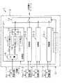
多重化システム1は、図1に示すように、一次多重化ストリームを生成する複数の一次多重化器11-1〜11-nと、各一次多重化器11-1〜11-nにより生成された一次多重化ストリームをさらに多重化して二次多重化ストリームを生成する二次多重化器12とを備えている。また、この二次多重化器12は、各一次多重化器11-1〜11-nにより生成された一次多重化ストリームを受信してそのストリームを加工する複数の受信部13-1〜13-nと、各受信部13-1〜13-nから出力された一次多重化ストリームを選択して二次多重化する二次選択部14と、各受信部13-1〜13-n及び二次選択部14を制御するシステムコントローラ15とを備えている。
【0057】
各一次多重化器11-1〜11-nは、仮想のデコーダバッファのバッファ占有量の上限及び下限値に所定のマージンを設けて、この仮想のデコーダバッファが破綻しないような符号量の一次多重化ストリームを生成する。各一次多重化ストリームは、それぞれ対応する受信部13-1〜13-nに供給される。なお、各一次多重化器11-1〜11-nは、互いに独立の基準クロックCp1〜Cpnに基づき動作している。各一次多重化器11-1〜11-nにより生成される一次多重化ストリームは、各基準クロックCp1〜Cpnに同期している。
【0058】
各一次多重化器11-1〜11nから出力された各一次多重化ストリームは、二次多重化器12内の対応する受信部13-1〜13-nに入力される。
【0059】
二次多重化器12は、基準クロックCrに基づき動作をする。この基準クロックCrは、各一次多重化器11-1〜11-nに与えられる基準クロックCp1〜Cpnと同期がとられておらず、各一次多重化器11-1〜11-nと二次多重化器12とは、非同期に動作をしている。
【0060】
二次多重化器12の各受信部13-1〜13-nは、一次多重化ストリームをPCRが付加されたTSパケットとそれ以外のTSパケットとに分離する分離部16と、PCRを補正するPCR補正部17と、PCRが付加されたTSパケット以外のパケットを一次的に格納する中間メモリ18と、NULLパケット(ISO/IEC13818-1に規定)やシステム情報(ISO/IEC13818-1や各放送規格により規定)が含まれるTSパケットを生成するTSP発生部19と、PCR補正部17,中間メモリ18,TSP発生部19から出力された各パケットを選択して多重化する一次選択部20とを備えている。
【0061】
各受信部13内の分離部16は、PCRが付与されているTSパケットと、それ以外のTSパケットとに、入力された一次多重化ストリームをTSパケット単位で分離する。TSパケットにPCRが付与されているかどうかは、adaptation_field内のPCR_flagを参照することによりわかる。TSパケット内にadaptation_fieldが設けられており、且つ、そのadaptation_field内のPCR_flagが1とされていれば、そのTSパケットにはPCRが付与されている。分離部16は、PCRが付与されているTSパケットをPCR補正部17に供給し、それ以外のTSパケットを中間メモリ18に供給する。
【0062】
PCR補正部17は、TSパケットに記述されているPCRの値を補正する。具体的には、一次多重化器11で元々算出されたPCRとそのパケットに生じる二次多重化ディレイ及び二次多重化ジッタとに基づき、そのTSパケットを二次多重化ストリームとして出力したときに正しい値となるようなPCR値を算出し、算出した値にPCRを書き換える。PCR補正部17は、後段の一次選択部14により選択された際に、PCRが付与されたTSパケットを出力する。
【0063】
中間メモリ18は、PCRが付与されているTSパケット以外のパケットを一時的に格納する。中間メモリ18は、後段の一次選択部14により選択された際に、一次多重化器11から受信した順序でTSパケットを出力する。
【0064】
TSP発生部19は、二次多重化をする際のタイミング補正をするために挿入するNULLパケットやシステム情報等が格納されたTSパケットを生成する。TSP発生部19は、後段の一次選択部14により選択された際に、生成したTSパケットを出力する。
【0065】
一次選択部20は、PCRが付与されたパケットが二次多重化ストリーム中で一定パケット毎に挿入されるように、PCR補正部17,中間メモリ18,TSP発生部19から出力されるTSパケットを適宜選択して、多重化していく。なお、この多重化のタイミングについては詳細を後述する。
【0066】
以上のような各受信部13は、入力された一次多重化ストリームに対して、PCRの値の補正や、NULLパケット及びシステム情報が格納されたTSパケットの挿入を行い、一次多重化ストリームを加工して出力する。
【0067】
二次多重化器12の二次選択部14は、各受信部13から出力される一次多重化ストリームをTSパケット単位で取り出し、この取り出したTSパケットを時分割多重化して、二次多重化ストリームを生成する。
【0068】
二次多重化器12のシステムコントローラ15は、各受信部13,二次選択部14の制御を行う。
【0069】
以上のような構成の多重化システム1では、二次選択部14及び受信部13内の一次選択部20により行われるTSパケットの選択処理によって、複数本の一次多重化ストリームが、一本の二次多重化ストリームに多重化される。
【0070】
(多重化システム1の多重化方式)
ここで、この多重化システム1では、二次選択部14及び一次選択部20によって、各一次多重化ストリームに関するPCRが付与されているパケットが、所定パケット周期毎で二次多重化ストリーム内に配置するように、TSパケットの選択を行っている。
【0071】
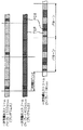
例えば、図2に示すように、2本の一次多重化ストリーム(一方をプログラムA、他方をプログラムBとする。)を多重化して二次多重化ストリームを生成する場合、プログラムAに関するPCRが付与されているTSパケットを例えば9パケット毎に必ず配置されるようにし、プログラムBに関するPCRが付与されているTSパケットを例えば3パケット毎に必ず配置されるようにしている。
【0072】
以下、各一次多重化ストリームに関するPCRが付与されているパケットが、所定パケット周期毎で二次多重化ストリーム内に配置されるように切換選択をするための第1から第5の処理方式について具体的に説明をする。
【0073】
--第1の処理方式--
まず、第1の処理方式について説明をする。
【0074】
第1の処理方式では、二次選択部14によって一次多重化ストリームを選択するための切換順番を設定した選択パターンを定めて多重化処理を行う。この選択パターンは、二次多重化ストリームを生成する際に、各一次多重化ストリームから選択するTSパケットの順序を定めた、TSパケットの選択のための繰り返しパターンである。二次選択部14は、この選択パターンに従い、各受信部13-1〜13-nのいずれか一つを選択し、選択した受信部13から1つのTSパケットを取り出し、二次多重化していく。
【0075】
この選択パターンは以下のように定められる。
【0076】
まず、1つの選択パターン内に含まれる全TSパケットの総数を設定する。例えば、図3(A)に示すように、5個のTSパケットから構成される選択パターンを設定する。
【0077】
続いて、選択パターン内の各パケット位置に、それぞれ各一次多重化ストリームに分配する。例えば、プログラムAとプログラムBの2本のトランスポートストリーム(一次多重化ストリーム)を二次多重化する場合、図3(B)に示すように、5個のTSパケットのうち、3つのパケットをプログラムAに割り当て(選択パターン内の1番目、3番目、5番目のパケット)、2つのパケットをプログラムBに割り当てる(選択パターン内の2番目、4番目のパケット)。
【0078】
続いて、二次多重化ストリームのビットレートと、各一次多重化ストリームに分配したTSパケットの数から、それぞれの一次多重化ストリームのビットレートを決定する。例えば、二次多重化ストリームのビットレートが1Mbpsであれば、図3(C)に示すように、プログラムAを600kbps、プログラムBを400kbpsに割り当てる。これらを各一次多重化器の割り当てビットレートという。
【0079】
以上のようにして、選択パターン並びに一次多重化ストリームのビットレートが決定される。なお、予め一次多重化ストリームのビットレートが決まっている場合には、各一次多重化ストリームのビットレートの比率から逆に選択パターンを定めるようにしてもよい。
【0080】
二次選択部14は、この設定された選択パターンに従い、一次多重化ストリームを順番に選択して、二次多重化していく。
【0081】
このように予め設定された選択パターンに従い二次多重化することによって、二次多重化ジッタを既知の値とすることができる。そのため、この選択パターンに応じて決定される二次多重化ジッタ分だけマージンをもって一次多重化ストリームを生成することによって、二次多重化した後にも復号側が破綻することがない。
【0082】
また、この第1の処理方式では、PCRが付与されているTSパケットが一定パケット数毎に配置された一次多重化ストリームを、各一次多重化器11から出力させる。PCRが付与されているTSパケットの発生間隔は、選択パターンに割り当てられたパケット数に対応する間隔である。
【0083】
例えば、5個のTSパケットから構成される選択パターンが設定され、プログラムAに3個のTSパケットが割り当てられ、プログラムBに2個のTSパケットが割り当てられている場合には、図4(A)に示すように、プログラムAを生成する一次多重化器11が3パケット毎にPCRを付与したTSパケットを出力し、プログラムBを生成する一次多重化器11が2パケット毎にPCRを付与したTSパケットを出力する。
【0084】
このように各一次多重化器11が、割り当てられたパケット数毎に、PCRが付与されているTSパケットを挿入した一次多重化ストリームを生成することによって、二次多重化ストリームを生成した際に、各一次多重化ストリームに関するPCRが付与されているパケットが、所定パケット周期毎で二次多重化ストリーム内に配置されることとなる。例えば、図4(B)に示すように、プログラムAに関するPCR及びプログラムBに関するPCRをそれぞれ5パケット毎に配置させた二次多重化ストリームを生成することができる。
【0085】
ところで、本多重化システム1は、一次多重化器11と二次多重化器12との基準クロックが同期していない非同期システムである。
【0086】
すなわち、一次多重化器11の基準クロックCpと二次多重化器12の基準クロックCrが同期している同期システムであれば、選択パターンどおりに二次多重化することで、二次多重化ジッタは一定量以上の値とならず、二次多重化ジッタは増加しない。例えば、図5(A)に示すように、同期システムの場合、二次多重化ジッタD(i)は、選択パターンでその最大値が既知となり、その最大値以上に増加しない。
【0087】
しかしながら、一次多重化器11と二次多重化器12の基準クロックが非同期の本実施の形態の多重化システム1の場合、選択パターンどおりに二次多重化していっても、基準クロックの差から生じる誤差が蓄積していき、二次多重化ジッタが増加していってしまう。例えば、図5(B)に示すように、二次多重化器12の基準クロックCrの方が一次多重化器11の基準クロックCpよりも大きければ、各パケットの多重化タイミングが進んでしまい、多重化が進めば進むほど二次多重化ジッタが増加してしまう。なお、二次多重化を行う場合には、実際には各パケットに固定的に発生する二次多重化ディレイも生じるが、二次多重化ジッタの増加を分かり易く説明するため、この図5では省略して示している。
【0088】
このように二次多重化ジッタが増加していくと、PCRの値と実際の受信タイミングとのずれが大きくなり、デコーダの処理が破綻してしまう。
【0089】
そのため、この第1の処理方式では、一次多重化ストリームの受信タイミングに対して、二次多重化ストリームの出力タイミングが時間的に進んでしまい、二次多重化ジッタがある閾値以上となったときに、ダミーデータ(NULLパケット)を強制的に挿入し、二次多重化ジッタを減少させる。
【0090】
例えば、図6に示すように、プログラムBのTSパケット(b2)の二次多重化ジッタD(2)は、閾値D(th)以下となっているため、特別な補正処理は行われていない。一方、TSパケット(b4)の二次多重化ジッタD(4)は、閾値D(th)より大きくなっている。そのため、本来の選択パターンでは、TSパケット(b5)を二次多重化する予定だった二次多重化ストリームの領域にダミーデータ(NULLパケット)を挿入する。
【0091】
そして、さらに、PCRが付与されているTSパケットを、所定パケット周期毎で二次多重化ストリーム内に配置させるため、以後PCRが付与されているパケットを、選択パターン内の所定の位置に配置するように、一次多重化ストリーム内のTSパケットの選択順序を切り換える。それとともに、TSパケットの選択順序の入れ替えによって生じるPCRの値を、元々一次多重化ストリームに付けられていたPCRの値に基づき、補正を行う。
【0092】
例えば、図6に示すように、NULLパケットが挿入された後のTSパケット(b6)にPCRが付与されているので、このTSパケット(b6)を選択パターンの2番目のパケット位置に配置し、PCRが付与されていないTSパケット(b5)を選択パターンの4番目のパケット位置に配置する。そして、このTSパケット(b6)に付与されているPCRの値を、元々付けられていた値を参照して、二次多重化出力をしたときに正しいPCR値に補正する。以後、PCRが付与されているTSパケット(b8)、TSパケット(b10)、TSパケット(b12)・・・を必ず選択パターン内の2番目のパケット位置に配置するように選択切換を行うとともに、そのPCR値の補正を行っていく。
【0093】
このように第1の処理方式では、二次多重化ストリームにダミーデータ(NULLパケット)を挿入ことによって、非同期システムであることによる二次多重化ジッタの増加を補正する。さらに、第1の処理方式では、ダミーデータ(NULLパケット)を挿入することに伴うPCRの付与位置のずれを、TSパケットの選択順序の切り換えと、そのPCRの補正とによって、修正する。このような処理を行うことによって、第1の処理方式では、各一次多重化ストリームに関するPCRが付与されているTSパケットが、所定パケット周期毎で二次多重化ストリーム内に配置されるように切換選択をすることができる。
【0094】
なお、この第1の処理方式では、一次多重化ストリームの受信タイミングに対して、二次多重化ストリームの出力タイミングが時間的に進むことを前提とし、二次多重化ジッタを補正することとなる。そのため、二次多重化器12の基準クロックCrが、一次多重化器11の基準クロックCpよりも早くなることを補償すれば、この第1の処理方法で確実に二次多重化処理を行うことができる。
【0095】
二次多重化器12の基準クロックCrが、一次多重化器11の基準クロックCpよりも早くなることを補償するには、例えば、一次多重化器の基準クロックの定格の最大値をCpMAX、二次多重化器の基準クロックの定格の最小値をCrMIX、選択パターンに基づき当該一次多重化器に割り当てられるビットレートをPとすれば、一次多重化器から出力される一次多重化ストリームのビットレートを以下のように設定すればよい。
【0096】
(CrMIN/CpMAX)×P
また、二次多重化ジッタの調整するためのダミーデータは、NULLパケットのみならず、システム情報が記述されたTSパケットを挿入するようにしてもよい。
【0097】
--第2の処理方式--
つぎに、第2の処理方式について説明をする。
【0098】
第2の処理方式では、二次選択部14によって一次多重化ストリームを選択するための切換順番を設定した選択パターンを定めて多重化処理を行う。この選択パターンは、上述した第1の処理方式と同様に定められる。
【0099】
また、この第2の処理方式では、PCRが付与されているTSパケットが、一定時間間隔毎に配置された一次多重化ストリームを、各一次多重化器11から出力させる。PCRが付与されているTSパケットの時間間隔は、選択パターンの周期に対応する時間間隔である。
【0100】
例えば、二次多重化ストリームのビットレートが1Mbpsであり、5個のTSパケットから構成される選択パターンが設定されているとすると、その選択パターンの周期は(T=5×8×188×10−6)となる。このとき、図7(A)に示すように、一次多重化器11は、周期T毎にPCRを付与したTSパケットを出力する。各一次多重化器11は、少なくとも周期T毎にPCRを挿入したTSパケット出力すれば、それ以外のTSパケットを自在に間引いてもよく、また、ダミーデータ(NULLパケット)を挿入してもよい。
【0101】
このように各一次多重化器11が、選択パターンの周期T毎に、PCRが付与されているTSパケットを挿入した一次多重化ストリームを生成することによって、二次多重化ストリームを生成した際に、各一次多重化ストリームに関するPCRが付与されているパケットが、所定パケット周期毎で二次多重化ストリーム内に配置されることとなる。例えば、図7(B)に示すように、プログラムAに関するPCR及びプログラムBに関するPCRをそれぞれ5パケット毎に配置させた二次多重化ストリームを生成することができる。なお、一次多重化ストリームの一部のパケットが間引かれていたり、ダミーパケットに置き換えられていた場合には、二次多重化ストリーム中の所定のパケット位置に、データが存在しないこととなる場合がある。その場合には、その空パケット位置に、NULLパケットやシステム情報が記述されたTSパケットを挿入するようにする。
【0102】
また、この第2の処理方式では、第1の処理方法と同様に、一次多重化ストリームの受信タイミングに対して、二次多重化ストリームの出力タイミングが時間的に進んでしまい、二次多重化ジッタがある閾値以上となったときに、ダミーデータ(NULLパケット)を強制的に挿入し、二次多重化ジッタを減少させる。
【0103】
そして、さらに、PCRが付与されているパケットを、所定パケット周期毎で二次多重化ストリーム内に配置させるため、以後PCRが付与されているパケットを、選択パターン内の所定の位置に配置するように、一次多重化ストリーム内のTSパケットの選択順序を切り換える。それとともに、TSパケットの選択順序の入れ替えによって生じるPCRの値を、元々一次多重化ストリームに付けられていたPCRの値に基づき、補正を行う。
【0104】
このように第2の処理方式では、ダミーデータ(NULLパケット)を挿入ことによって、非同期システムであることによる二次多重化ジッタの増加を補正する。さらに、第2の処理方式では、ダミーデータ(NULLパケット)を挿入することに伴うPCRの付与位置のずれを、TSパケットの選択順序の切り換えと、そのPCRの補正とによって、修正する。このような処理を行うことによって、第2の処理方式では、各一次多重化ストリームに関するPCRが付与されているパケットが、所定パケット周期毎で二次多重化ストリーム内に配置されるように切換選択をすることができる。
【0105】
また、この第2の処理方式でも、第1の処理方式と同様に、一次多重化ストリームの受信タイミングに対して、二次多重化ストリームの出力タイミングが時間的に進むことを前提とし、二次多重化ジッタを補正することとなる。そのため、この第2の処理方式でも、下式に示すように、二次多重化器12の基準クロックCrが、一次多重化器11の基準クロックCpよりも早くなることを補償する。
【0106】
(CrMIN/CpMAX)×P
--第3の処理方式--
つぎに、第3の処理方式について説明をする。
【0107】
第3の処理方式では、二次選択部14によって一次多重化ストリームを選択するための切換順番を設定した選択パターンを定めて多重化処理を行う。この選択パターンは、上述した第1の処理方式と同様に定められる。
【0108】
また、この第3の処理方式では、PCRが付与されているTSパケットが一定パケット数毎に配置された一次多重化ストリームを、各一次多重化器11から出力させる。PCRが付与されているTSパケットの発生間隔は、選択パターンに割り当てられたパケット数に対応する間隔である。このPCRが付与されているTSパケットの発生間隔は、上述した第1の処理方式と同様に定められる。
【0109】
また、第3の処理方式では、一次多重化ストリームの受信タイミングに対して、二次多重化ストリームの出力タイミングが時間的に遅れてしまい、二次多重化ジッタがある閾値以上となったときに、一次多重化ストリームからダミーデータ(NULLパケット)を強制的に削除し、二次多重化ジッタを減少させる。なお、ダミーデータの強制的な削除を可能とするように、一次多重化器11は、予め適当な間隔でダミーデータ(NULLパケット)を挿入した一次多重化ストリームを生成しておく。
【0110】
例えば、図8に示すように、プログラムBのTSパケット(b2)の二次多重化ジッタD(2)は、閾値D(th)以下となっているため、特別な補正処理は行われていない。一方、TSパケット(b4)の二次多重化ジッタD(4)は、閾値D(th)より大きくなっている。そのため、このTSパケット(b4)の次のNULLパケット(ここでは、b5)を削除する。
【0111】
そして、さらに、PCRが付与されているパケットを、所定パケット周期毎で二次多重化ストリーム内に配置させるため、以後PCRが付与されているパケットを、選択パターン内の所定の位置に配置するように、一次多重化ストリーム内のTSパケットの選択順序を切り換える。それとともに、TSパケットの選択順序の入れ替えによって生じるPCRの値を、元々一次多重化ストリームに付けられていたPCRの値に基づき、補正を行う。
【0112】
ここでは、図8に示すように、NULLパケットが削除された後のTSパケット(b6)にPCRが付与されているので、TSパケット(b6)とTSパケット(b7)との選択順序を入れ替え、TSパケット(b6)を選択パターン中の2番目のパケット位置に配置し、PCRが付与されていないTSパケット(b7)を選択パターンの4番目のパケット位置に配置する。そして、このTSパケット(b6)に付与されているPCRの値を、元々付けられていた値を参照して、二次多重化出力をしたときに正しいPCR値に補正する。以後、PCRが付与されているTSパケット(b8)、TSパケット(b10)、TSパケット(b12)・・・を必ず選択パターン内の2番目のパケット位置に配置するように選択切換を行うとともに、そのPCR値の補正を行っていく。
【0113】
このように第3の処理方式では、一次多重化ストリームからダミーデータ(NULLパケット)を削除ことによって、非同期システムであることによる二次多重化ジッタの増加を補正する。さらに、第3の処理方式では、ダミーデータ(NULLパケット)を削除することに伴うPCRの付与位置のずれを、TSパケットの選択順序の切り換えと、そのPCRの補正とによって、修正する。このような処理を行うことによって、第3の処理方式では、各一次多重化ストリームに関するPCRが付与されているパケットが、所定パケット周期毎で二次多重化ストリーム内に配置されるように切換選択をすることができる。
【0114】
なお、この第3の処理方式では、一次多重化ストリームの受信タイミングに対して、二次多重化ストリームの出力タイミングが時間的に遅れることを前提とし、二次多重化ジッタを補正することとなる。そのため、二次多重化器12の基準クロックCrが、一次多重化器11の基準クロックCpよりも遅くなることを補償すれば、第3の処理方法で確実に二次多重化処理を行うことができる。
【0115】
二次多重化器12の基準クロックCrが、一次多重化器11の基準クロックCpよりも遅くなることを補償するには、例えば、一次多重化器の基準クロックの定格の最大値をCpMAX、二次多重化器の基準クロックの定格の最小値をCrMIN、選択パターンに基づき当該一次多重化器に割り当てられるビットレートをPとすれば、一次多重化器から出力される一次多重化ストリームのビットレートを以下のように設定すればよい。
【0116】
(CpMAX/CrMIN)×P
--第4の処理方式--
つぎに、第4の処理方式について説明をする。
【0117】
第4の処理方式では、二次選択部14によって一次多重化ストリームを選択するための切換順番を設定した選択パターンを定めて多重化処理を行う。この選択パターンは、上述した第1の処理方式と同様に定められる。
【0118】
また、この第4の処理方式では、PCRが付与されているTSパケットが一定時間間隔毎に配置された一次多重化ストリームを、各一次多重化器11から出力させる。PCRが付与されているTSパケットの時間間隔は、選択パターンの周期に対応する時間間隔である。この時間間隔は、上述した第2の処理方式と同様に定められる。
【0119】
また、この第4の処理方式では、第3の処理方法と同様に、一次多重化ストリームの受信タイミングに対して、二次多重化ストリームの出力タイミングが時間的に遅れてしまい、二次多重化ジッタがある閾値以上となったときに、一次多重化ストリームからダミーデータ(NULLパケット)を強制的に削除し、二次多重化ジッタを減少させる。
【0120】
そして、さらに、PCRが付与されているパケットを、所定パケット周期毎で二次多重化ストリーム内に配置させるため、以後PCRが付与されているパケットを、選択パターン内の所定の位置に配置するように、一次多重化ストリーム内のTSパケットの選択順序を切り換える。それとともに、TSパケットの選択順序の入れ替えによって生じるPCRの値を、元々一次多重化ストリームに付けられていたPCRの値に基づき、補正を行う。
【0121】
このように第4の処理方式では、ダミーデータ(NULLパケット)を削除することによって、非同期システムであることによる二次多重化ジッタの増加を補正する。さらに、第4の処理方式では、ダミーデータ(NULLパケット)を削除することに伴うPCRの付与位置のずれを、TSパケットの選択順序の切り換えと、そのPCRの補正とによって、修正する。このような処理を行うことによって、第4の処理方式では、各一次多重化ストリームに関するPCRが付与されているパケットが、所定パケット周期毎で二次多重化ストリーム内に配置されるように切換選択をすることができる。
【0122】
また、この第4の処理方式でも、第3の処理方式と同様に、一次多重化ストリームの受信タイミングに対して、二次多重化ストリームの出力タイミングが時間的に遅れることを前提とし、二次多重化ジッタを補正することとなる。そのため、下式に示すように、二次多重化器12の基準クロックCrが、一次多重化器11の基準クロックCpよりも早くなることを補償する。
【0123】
(CpMIN/CrMIN)×P
--第5の処理方式--
つぎに、第5の処理方式について説明をする。
【0124】
第5の処理方式では、二次選択部14によって一次多重化ストリームを選択するための切換順番を設定した選択パターンを定めて多重化処理を行う。この選択パターンは、上述した第1の処理方式と同様に定められる。
【0125】
また、この第5の処理方式では、PCRが付与されているTSパケットが一定パケット数毎に配置された一次多重化ストリームを、各一次多重化器11から出力させる。PCRが付与されているTSパケットの発生間隔は、選択パターンに割り当てられたパケット数に対応する間隔である。このPCRが付与されているTSパケットの発生間隔は、上述した第1の処理方式と同様に定められる。なお、第5の処理方式において、第2の処理方式と同様に、PCRが付与されているTSパケットが時間間隔毎に配置された一次多重化ストリームを、各一次多重化器11から出力させるようにしてもよい。
【0126】
また、この第5の処理方式では、一次多重化ストリームの受信タイミングに対して、二次多重化ストリームの出力タイミングが時間的に進んでしまい、二次多重化ジッタがある閾値以上となったときに、ダミーデータ(NULLパケット)を強制的に挿入し、二次多重化ジッタを減少させる。また、同時に、この第5の処理方式では、一次多重化ストリームの受信タイミングに対して、二次多重化ストリームの出力タイミングが時間的に遅れてしまい、二次多重化ジッタがある閾値以上となったときに、一次多重化ストリームからダミーデータ(NULLパケット)を強制的に削除し、二次多重化ジッタを減少させる。
【0127】
すなわち、第5の処理方式では、一次多重化ストリームからのダミーデータの削除、及び、二次多重化データへのダミーデータの挿入の両者を行って、二次多重化ジッタを減少させる。
【0128】
そして、さらに、PCRが付与されているパケットを、所定パケット周期毎で二次多重化ストリーム内に配置させるため、以後PCRが付与されているパケットを、選択パターン内の所定の位置に配置するように、一次多重化ストリーム内のTSパケットの選択順序を切り換える。それとともに、TSパケットの選択順序の入れ替えによって生じるPCRの値を、元々一次多重化ストリームに付けられていたPCRの値に基づき、補正を行う。
【0129】
このように第5の処理方式では、ダミーデータ(NULLパケット)の挿入及び削除をすることによって、非同期システムであることによる二次多重化ジッタの増加を補正する。さらに、第5の処理方式では、ダミーパケット(NULLパケット)を挿入及び削除することに伴うPCRの付与位置のずれを、TSパケットの選択順序の切り換えと、そのPCRの補正とによって、修正する。このような処理を行うことによって、第5の処理方式では、各一次多重化ストリームに関するPCRが付与されているパケットが、所定パケット周期毎で二次多重化ストリーム内に配置されるように切換選択をすることができる。
【0130】
また、この第5の処理方式では、一次多重化ストリームの受信タイミングに対して、二次多重化ストリームの出力タイミングが時間的に進むこと、或いは、時間的に遅れることを前提としないので、一次多重化器11及び二次多重化器12の基準クロックの補償をしなくても、処理を行うことができる。
【0131】
第2の実施の形態
つぎに、本発明の第2の実施の形態の多重化システムについて、図面を参照しながら説明する。なお、この第2の実施の形態の多重化システムを説明するにあたり、上述した第1の実施の形態の多重化システム1と同一の構成要素については図面中に同一の符号を付け、その詳細な説明を省略する。
【0132】
図9に、本発明の第2の実施の形態の多重化システムのブロック構成図を示す。
【0133】
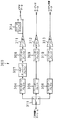
多重化システム30は、図9に示すように、一次多重化ストリームを生成する複数の一次多重化器11-1〜11-nと、各一次多重化器11-1〜11-nにより生成された一次多重化ストリームをさらに多重化して二次多重化ストリームを生成する二次多重化器32とを備えている。また、この二次多重化器32は、各一次多重化器11-1〜11-nにより生成された一次多重化ストリームを受信してそのストリームの加工を行う複数の受信部33-1〜33-nと、各受信部33-1〜33-nから出力された一次多重化ストリームを選択して二次多重化する二次選択部34と、各受信部33-1〜33-n及び二次選択部34を制御するシステムコントローラ15とを備えている。
【0134】
各一次多重化器11-1〜11nから出力された各一次多重化ストリームは、二次多重化器32内の対応する受信部33-1〜33-nに入力される。
【0135】
二次多重化器32は、基準クロックCrに基づき動作をする。この基準クロックCrは、各一次多重化器11-1〜11-nに与えられる基準クロックCp1〜Cpnと同期がとられておらず、各一次多重化器11-1〜11-nと二次多重化器32とは、非同期に動作をしている。
【0136】
二次多重化器32の各受信部33-1〜33-nは、一次多重化ストリームをPCRが付加されたTSパケットとそれ以外のTSパケットとに分離する分離部36と、一次多重化ストリームに付与されていたPCRを削除するPCR削除部37と、PCRを新たに生成するPCR生成部38と、PCRが付加されたTSパケット以外のパケットを一次的に格納する中間メモリ39と、NULLパケット(ISO/IEC13818-1に規定)やシステム情報(ISO/IEC13818-1や各放送規格により規定)が含まれるTSパケットを生成するTSP発生部40と、PCR削除部37,PCR生成部38,中間メモリ39,TSP発生部40から出力された各パケットを選択して多重化する一次選択部41とを備えている。
【0137】
各受信部33内の分離部36は、PCRが付与されているTSパケットと、それ以外のTSパケットとに、入力された一次多重化ストリームをTSパケット単位で分離する。TSパケットにPCRが付与されているかどうかは、adaptation_field内のPCR_flagを参照することによりわかる。分離部36は、PCRが付与されているTSパケットをPCR削除部37及びPCR生成部38に供給し、それ以外のTSパケットを中間メモリ39に供給する。
【0138】
PCR削除部37は、元々の一次多重化ストリームに付与されているPCRをダミーデータに置き換える処理を行う。具体的には、図10に示すように、TSパケットにPCRが記述されている場合には、adaptation_field内に記述されているPCR_Flagの値を“1”が記述され、さらに、続く6バイトにPCRが符号化されている。PCR削除部37は、PCR_Flagの値を1から0に置き換えるとともに、続く6バイトのPCRを削除して、adaptation_fieldの最後にstuffing_byteを挿入する。このような処理を行うことにより、adaptation_field及びTSパケットのバイト長を変更することなく、PCRを削除することができる。
【0139】
PCR生成部38は、二次多重化したときに挿入する新たなPCRが付加されたTSパケットを生成する。具体的には、一次多重化器11で元々算出されたPCRに基づき、そのTSパケットを二次多重化ストリームとして出力したときに正しい値となるようなPCR値を算出し、算出した値のPCRを付加したTSパケットを生成する。PCR補正部38は、後段の一次選択部41により選択された際に、PCRが付与されたTSパケットを出力する。
【0140】
中間メモリ39は、PCRが付与されているTSパケット以外のパケットを一時的に格納する。中間メモリ39は、後段の一次選択部41により選択された際に、一次多重化器11から受信した順序でTSパケットを出力する。
【0141】
TSP発生部40は、二次多重化をする際のタイミング補正をするために挿入するNULLパケットやシステム情報等が格納されたTSパケットを生成する。TSP発生部40は、後段の一次選択部41により選択された際に、生成したTSパケットを出力する。
【0142】
一次選択部41は、PCRが付与されたTSパケットが二次多重化ストリーム中で一定パケット毎に挿入されるように、PCR削除部37,PCR生成部38,中間メモリ39,TSP発生部40から出力されるTSパケットを適宜選択して、多重化していく。なお、この多重化のタイミングについては詳細を後述する。
【0143】
以上のような各受信部33は、入力された一次多重化ストリームに対して、PCRの値の補正や、NULLパケット及びシステム情報が格納されたTSパケットの挿入を行い、一次多重化ストリームを加工して出力する。
【0144】
二次多重化器32の二次選択部34は、各受信部33から出力される一次多重化ストリームをTSパケット単位で取り出し、この取り出したTSパケットを時分割多重化して、二次多重化ストリームを生成する。
【0145】
二次多重化器32のシステムコントローラ35は、各受信部33,二次選択部34の制御を行う。
【0146】
以上のような構成の多重化システム30では、二次選択部34及び受信部33内の一次選択部41により行われるTSパケットの選択処理によって、複数本の一次多重化ストリームが、一本の二次多重化ストリームに多重化される。
【0147】
(多重化システム30の多重化方式)
この多重化システム30では、二次選択部34及び一次選択部41によって、各一次多重化ストリームに関するPCRが付与されているパケットが、所定パケット周期毎で二次多重化ストリーム内に配置するように、TSパケットの選択を行っている。
【0148】
各一次多重化ストリームに関するPCRが付与されているパケットが、所定パケット周期毎で二次多重化ストリーム内に配置されるように切換選択をするための方式は、上記第1の実施の形態の第1から第5の処理方式と同様である。
【0149】
ただし、PCRが付与されたTSパケットは、PCR生成部38で新たに生成されるため、PCR生成部38の出力から選択されることとなる。また、各一次多重化器に割り当てら得るビットレートPは、新たに生成されるTSパケット(PCRが付与されたTSパケット)の挿入数を考慮して算出される。例えば、図3に示したように、二次多重化ストリームのビットレートが1Mbpsであり、5個のTSパケットから構成される選択パターンを設定し、そのうち、プログラムAに3個のTSパケット、プログラムBに2個のTSパケットを割り当てたとする。そして、各選択パターン内にプログラムA及びプログラムBともに1つのPCRが付与されたTSパケットが配置されるものとする。そのときには、プログラムAのビットレートは、4kbpsに割り当てられ、プログラムBのビットレートは2kbpsに割り当てら得ることとなる。
【0150】
以上のように本発明の第1の実施の形態の多重化システム1及び第2の実施の形態の多重化システム30では、二次多重化を行う際に、それぞれの一次多重化ストリームに関するPCRが付与されているパケットを、所定パケット周期毎で二次多重化ストリーム内に配置する。
【0151】
このことにより、多重化システム1,30では、一次多重化ストリームと二次多重化ストリームとを非同期の基準クロックに基づき生成することができるとともに、二次多重化ジッタを少なくして、受信側や復号側の処理を破綻させることがない二次多重化ストリームを生成することができる。さらに、多重化システム1,30では、二次多重化ストリームの一定の位置に時間基準参照値を配置することができ、二次多重化ストリーム中の一部分のTSパケットのみを受信する受信方式であっても、受信側に確実にシステムクロックを復元させることができる。
【0152】
例えば、OFDM変調方式を採用したデジタル放送などで、1つの放送周波数チャネル中の一部分の帯域の信号だけを抽出して受信可能とした部分受信を実現した放送方式では、1つのトランスポートストリーム中の一部分のTSパケットのみを復号する場合がある。このような部分受信をする場合であっても、本発明では、抽出した一部分のTSパケット内にPCRを確実に含めることができ、受信側に確実にシステムクロックを復元させることができる。
【0153】
なお、本発明の実施の形態の多重化システムの切換処理を説明するにあたり、選択パターンを用いて、PCRが付与されているパケットを、所定パケット周期毎に二次多重化ストリーム内に配置する処理例を示した。しかしながら、本発明では、このような選択パターンを設定せずに、切換処理を行ってもよい。例えば、中間メモリ18,39に格納しているパケット数が多い一次多重化ストリームから順にTSパケットを選択して二次多重化処理を行っていってもよいし、早く受信したTSパケットから順に選択して二次多重化処理を行っていってもよい。もっとも、このような場合であっても、各一次多重化ストリームに関するPCRが付与されているパケットを、所定パケット周期毎に二次多重化ストリーム内に配置するように切換処理を行う。
【0154】
また、二次多重化ジッタは、TSパケットの先頭タイミングで検出しているように図面中では示しているが、TSパケット内の検出位置が固定されていれば、TSパケットの先頭に限らず、どのTSパケット内のデータ位置でジッタを検出するようにしてもよい。
【0155】
【発明の効果】
本発明にかかるデジタル信号多重化装置及び方法では、二次多重化を行う際に、それぞれの一次多重化ストリームに関する時間基準参照値が付与されているパケットを、所定パケット周期毎で二次多重化ストリーム内に配置する。
【0156】
このことにより、本発明にかかるデジタル信号多重化装置及び方法では、一次多重化ストリームと二次多重化ストリームとを非同期の基準クロックに基づき生成することができるとともに、二次多重化ジッタを少なくして、受信側や復号側の処理を破綻させることがない二次多重化ストリームを生成することができる。さらに、このデジタル信号多重化装置では、二次多重化ストリームの一定の位置に時間基準参照値を配置することができ、二次多重化ストリーム中の一部分のパケットのみを受信する受信方式であっても、受信側に確実にシステムクロックを復元させることができる。
【0157】
例えば、OFDM(Orthogonal Frequency Division Multiplexing)変調方式を採用したデジタル放送などで、1つの放送周波数チャネル中の一部分の帯域の信号だけを抽出して受信可能とした部分受信を実現した放送方式では、1つのトランスポートストリーム中の一部分のTSパケットのみを復号する場合がある。このような部分受信をする場合であっても、本発明では、抽出した一部分のTSパケット内にPCRを確実に含めることができ、受信側に確実にシステムクロックを復元させることができる。
【図面の簡単な説明】
【図1】本発明の第1の実施の形態の多重化システムのブロック構成図である。
【図2】各一次多重化ストリームに関するPCRが付与されているパケットを、所定パケット周期毎で二次多重化ストリーム内に配置した例を説明するための図である。
【図3】選択パターンの設定方法を説明するための図である。
【図4】PCRが付与されているパケットの配置例を説明するための図である。
【図5】二次多重化ジッタについて説明するための図である。
【図6】二次多重化ストリームへのNULLパケットの挿入例を説明するための図である。
【図7】PCRが付与されているTSパケットが一定時間間隔毎に配置された一次多重化ストリームを、説明するための図である。
【図8】一次多重化ストリームからのNULLパケットの削除例を説明するための図である。
【図9】本発明の第2の実施の形態の多重化システムのブロック構成図である。
【図10】PCRの書き換え処理を説明するための図である。
【図11】デジタル放送等に用いられるトランスポートストリームを伝送する放送システムのブロック構成図である。
【図12】ISO33818-1で規定されるトランスポートストリームである一次多重化ストリーム及び二次多重化ストリームのデータ構造を示す図である。
【図13】ISO33818-1で規定されるTSパケットのデータ構造を示す図である。
【図14】上記放送システムのデコーダモデルを説明するための図である。
【図15】特開平11-235083号公報において提案されている二次多重化方法について説明するための図である。
【図16】特開平11-235083号公報において提案されている二次多重化方法で多重化をした場合に生じる二次多重化ジッタについて説明するための図である。
【図17】特開平11-235082号公報において提案されている二次多重化方法で多重化をした場合に生じる二次多重化ジッタについて説明するための図である。
【図18】ISDB−Tで採用されている部分受信について説明するための図である。
【符号の説明】
1,30 多重化システム、11 一次多重化器、12,32 二次多重化器、13,33 受信部、14,34 二次選択部、15,35 システムコントローラ、16,36 分離部、17 PCR補正部、18,39 中間メモリ、19,40 TSP発生部、20,41 一次選択部、37 PCR削除部,38 PCR生成部[0001]
BACKGROUND OF THE INVENTION
The present invention multiplexes digital signals such as video and audio to generate a primary multiplexed stream including a program such as a television or radio program, and further secondary-multiplexes the one or more primary multiplexed streams. The present invention relates to a digital signal multiplexing apparatus and method for generating a secondary multiplexed stream.
[0002]
[Prior art]
A transport stream for multiplexing and transmitting one or more programs (for example, services in which broadcast programs in television broadcasting are continuously organized) into one multiplexed stream is defined in ISO / IEC13818-1. Conventionally, a multiplexing system for generating this transport stream is known.
[0003]
FIG. 11 shows an example of a broadcast system configuration for transmitting a transport stream using digital broadcasting or the like.
[0004]
The
[0005]
Each encoded elementary stream is supplied to a primary multiplexer 113 (113-1 to 113-n) corresponding to each program. Each
[0006]
A plurality of primary multiplexed streams generated by the
[0007]
The
[0008]
Here, the primary multiplexed stream and the secondary multiplexed stream multiplexed by each
[0009]
As described above, the
[0010]
The secondary multiplexed stream is transmitted to the
[0011]
The
[0012]
As described above, the
[0013]
FIG. 11 shows an example in which the primary multiplexer generates a transport stream consisting of one program consisting of video and audio, but the program is not limited to a combination of video and audio, and In some cases, a plurality of programs are multiplexed in the transport stream output from the primary multiplexer.
[0014]
FIG. 12 shows the data structure of the primary multiplexed stream and the secondary multiplexed stream, which are transport streams defined by ISO / IEC13818-1.
[0015]
Each primary multiplexer divides the video elementary stream encoded by the video encoder and the audio elementary stream encoded by the audio encoder into TS packets having a fixed length of 188 bytes. A primary multiplexing process is performed by time division to generate a primary multiplexed stream. Subsequently, the secondary multiplexer further performs secondary multiplexing processing on each primary multiplexed stream in a time division manner in units of the TS packets to generate a secondary multiplexed stream. Thus, the primary multiplexed stream and the secondary multiplexed stream have a stream configuration multiplexed in units of TS packets.
[0016]
FIG. 13 shows the data structure of the TS packet. The TS packet has a total data of 188 bytes, and includes a fixed header, an optional adaptation field, and data bytes. In the adaptation field, a time reference reference value (PCR: Program Clock Reference), a stuffing_byte for size adjustment, and the like are encoded.
[0017]
PCR is a time base reference value that represents the arrival time of data (that is, the output time of data in the multiplexer). In the receiving apparatus, the system clock of the transmitting apparatus is restored by performing, for example, PLL synchronization using this PCR.
[0018]
FIG. 14 shows a decoder model of the
[0019]
For example, the
[0020]
Each of the
[0021]
The video data leaked from the
[0022]
From the multiplexing
[0023]
In the receiving
[0024]
The primary multiplexer of the
[0025]
By the way, in a multiplexing system such as that used in the above-described broadcasting system, that is, a multiplexing system in which a primary multiplexed stream that has been subjected to primary multiplexing is further multiplexed to generate a single secondary multiplexed stream, Due to the reasons mentioned above, there is a time lag between the output timing of the primary multiplexed stream scheduled by each primary multiplexer and the output timing of the primary multiplexed stream multiplexed in the secondary multiplexed stream. End up.
[0026]
(1) The secondary multiplexing can be performed only in the time slot of TS packet unit at the bit rate of the secondary multiplexed stream.
(2) The bit rate of the secondary multiplexed stream is higher than the bit rate of the primary multiplexed stream.
(3) Since the TS packet that can be secondarily multiplexed into a certain time slot is only one TS packet of the primary multiplexed stream, the TS packet of the primary multiplexed stream output from the primary multiplexer at approximately the same time is kept waiting. End up.
[0027]
Here, a time lag generated between the output timing of the primary multiplexed stream scheduled by each primary multiplexer and the output timing of the primary multiplexed stream multiplexed in the secondary multiplexed stream is reduced to two. This is called next multiplexing jitter.
[0028]
Therefore, in such a multiplexing system, even if the primary multiplexed stream is generated by scheduling so that the decoder buffer provided in the preceding stage of the decoder does not fail by the primary multiplexer, this secondary multiplexed jitter occurs, and the decoder A deviation occurs in the arrival timing of the data stream to the buffer, or a deviation occurs in the time base reference value encoded in the secondary multiplexed stream (PCR if the transport stream is defined in ISO13818-1). Or For this reason, there has been a problem that the decoder buffer fails due to the influence of these shifts.
[0029]
In order to solve the above problem, a pattern that determines the order of time-division multiplexing of TS packets extracted from the primary multiplexed stream is set in advance, and TS packets are sequentially selected from the primary multiplexed stream according to this pattern. Accordingly, the present applicant has proposed a multiplexing method for generating a secondary multiplexed stream without reducing the secondary multiplexing jitter and correcting the time base reference value (PCR) in Japanese Patent Laid-Open No. 11-215083. Yes.
[0030]
The secondary multiplexing method proposed in Japanese Patent Laid-Open No. 11-215083 will be briefly described below with reference to FIG.
[0031]
A plurality of primary multiplexed streams are input to the secondary multiplexer. The secondary multiplexer sets a pattern that defines the selection order of TS packets. This pattern is a predetermined pattern indicating in what order TS packets are extracted from a plurality of primary multiplexed streams and subjected to secondary multiplexing. The secondary multiplexer performs secondary multiplexing by periodically repeating this pattern. Further, the bit rate of each primary multiplexed stream is set based on the number of TS packets of each primary multiplexed stream included in this pattern and the bit rate of the secondary multiplexed stream. For example, when two primary multiplexed streams of program A and program B are multiplexed to generate a 1 Mbps secondary multiplexed stream, three TS packets of program A and one TS packet of program B are included in one pattern. Are included, the program A bit rate is set to 600 kbps, and the program B bit rate is set to 400 kbps. Or conversely, the bit rate of the pattern and the secondary multiplexed stream may be determined based on the bit rate of each primary multiplexer. Each primary multiplexer then adds a PCR to each TS packet number of the primary multiplexed transport stream included in the pattern (for example, in the example of FIG. Program B assigns PCR every 2 TS packets.), It becomes possible to assign PCR to a fixed position in the pattern of the secondary multiplexed stream.
[0032]
Note that the secondary multiplexing delay shown in FIG. 15 is a delay time that occurs fixedly when performing secondary multiplexing. Therefore, even if this secondary multiplexing delay occurs, there is no problem that the decoder buffer fails.
[0033]
In the secondary multiplexing method proposed in Japanese Patent Application Laid-Open No. 11-215083, if the reference clock Cp of the primary multiplexer and the reference clock Cr of the secondary multiplexer are synchronized, Multiplexed jitter occurs only up to a fixed amount fixed in the pattern. Therefore, since the upper limit of the secondary multiplexing jitter can be determined, if the primary multiplexed stream is generated with a margin for the upper limit of the capacity of the decoder buffer assumed in advance, the secondary multiplexing is performed. However, it does not cause a failure in the decoder buffer.
[0034]
However, for example, when the primary multiplexer and the secondary multiplexer are completely different devices, a system configuration in which the reference clock Cp of the primary multiplexer and the reference clock Cr of the secondary multiplexer are asynchronous. Must. In the case of such an asynchronous system, the secondary multiplexing method proposed in the above-mentioned Japanese Patent Application Laid-Open No. 11-215083, for example, continues the secondary multiplexing according to the pattern as shown in FIG. Even so, there is a problem that a secondary multiplexing timing shift (secondary multiplexing jitter) due to a reference clock shift occurs, and the more the multiplexing is advanced, the more the secondary multiplexing jitter is accumulated. is there.
[0035]
That is, when the bit rate P is assigned to each primary multiplexer based on the number of TS packets that are secondarily multiplexed in the pattern, the primary multiplexer is configured to use the bit rate P in the reference clock Cp of the primary multiplexer. The primary multiplexed stream is output, and the secondary multiplexer performs secondary multiplexing of the primary multiplexed stream at the bit rate P at the reference clock Cr of the secondary multiplexer. As described above, when multiplexing is performed using a unique reference clock, errors in the reference clock accumulate as secondary multiplexing jitter as the multiplexing progresses.
[0036]
If the secondary multiplexing jitter accumulates, the buffer in the receiving apparatus overflows or underflows, and the secondary multiplexing timing of PCR shifts, so that the system clock on the transmitting side cannot be correctly restored in the receiving apparatus. Will occur.
[0037]
In order to solve such a problem, a pattern that determines the order of time division multiplexing of TS packets extracted from the primary multiplexed stream is set in advance, and TS packets are selected in order from the primary multiplexed stream according to this pattern. Furthermore, the present applicant has disclosed a multiplexing method in which dummy data is multiplexed and the accumulated secondary multiplexing jitter is canceled when the secondary multiplexing jitter exceeds a certain amount. -215082.
[0038]
The secondary multiplexing method proposed in Japanese Patent Laid-Open No. 11-215082 will be briefly described below with reference to FIG. In the secondary multiplexer, the secondary multiplexing processing proposed in the above-mentioned Japanese Patent Application Laid-Open No. 11-215083 is performed, and further, the secondary multiplexing jitter D (i) is monitored, and this secondary multiplexing is performed. When the jitter D (i) is equal to or greater than the threshold value, a dummy TS packet (for example, NULL TSP defined in ISO / IEC13818-1) is inserted, thereby avoiding the accumulation of shifts in the secondary multiplexing timing. The secondary multiplexer corrects and outputs the PCR in accordance with the secondary multiplexing output timing. Further, in order to be able to correct the secondary multiplexing jitter D (i) by inserting a dummy TS packet (NULL TSP), the bit rate assigned to the primary multiplexer is secondary multiplexed in the pattern. The bit rate is assigned to be smaller than the bit rate P determined based on the number of TS packets. For example, if the maximum system clock rating of the primary multiplexer is CpMAX and the minimum system clock rating of the secondary multiplexer is CrMIN, the bit rate assigned to the primary multiplexer is (CrMIN / By setting CpMAX) * P, the secondary multiplexing timing is always advanced, and correction is possible by inserting a dummy TS packet (NULL TSP).
[0039]
However, in the secondary multiplexing method proposed in Japanese Patent Application Laid-Open No. 11-215082, even if PCR is added to each TS packet number of the primary multiplexed transport stream included in the pattern, secondary multiplexing is performed. By inserting a dummy TS packet (NULL TSP) to correct the timing shift, the position in the pattern of the TS packet to which the PCR is attached is shifted. Alternatively, even if the primary multiplexer assigns PCR every time period corresponding to the pattern, the dummy TS packet (NULL TSP) is inserted to correct the secondary multiplexing timing shift, thereby causing the PCR. Will be out of position in the pattern of TS packets to which.
[0040]
For example, as shown in FIG. 17, when a primary multiplexed stream of program A having a bit rate of 600 kbps is multiplexed to generate a secondary multiplexed stream of 1 Mbps, 3 TS packets of program A are included in one pattern. Will be included. If the primary multiplexer transmits a TS packet to which PCR is attached every 3 packets, the TS to which this PCR is attached at a fixed position in the pattern (the first packet of the pattern in FIG. 17). Packets will be placed. However, when a dummy TS packet (NULL TSP) is inserted, the position where the PCR is arranged is shifted (in FIG. 17, the position of the PCR is shifted from the first packet of the pattern to the third packet). .)
[0041]
[Problems to be solved by the invention]
By the way, in terrestrial digital broadcasting, in order to reduce the influence of reception interference due to multipath, the OFDM method is generally adopted as a modulation method of broadcast waves. The OFDM system is also adopted in ISDB-T (Intergrated Services Digital Broadcasting-Terrestorial), a terrestrial digital broadcasting system in Japan. In the OFDM system, modulation is performed by performing IFFT (Inverse Fast Fourier Transform) at the time of transmission and FFT (Fast Fourier Transform) at the time of reception.
[0042]
In this ISDB-T, a method called partial reception is adopted so that only a signal in a partial frequency band among OFDM signals transmitted in one frequency channel can be received. When broadcasting using this partial reception method, a wideband receiver that can receive all signals of one frequency channel and a narrowband receiver that can receive only a part of signals of one frequency channel, The broadcast can be received. By adopting such a partial reception method, for example, only an audio signal in a television broadcast can be received by an audio receiver, or only main information can be received by a narrowband receiver. When it is desired to receive information, it can be realized by receiving it with a broadband receiver, and the broadcast can be extended.
[0043]
Here, when such a partial reception method is employed, one transport stream is basically broadcast on one frequency channel, but a broadband receiver broadcasts on that frequency channel. This means that all TS packets of a transport stream can be received, whereas a narrowband receiver can receive only a part of the TS packets of the transport stream broadcast on that frequency channel. It will be.
[0044]
For example, as shown in FIG. 18, if six TS packets are transmitted in one symbol, a wideband receiver can receive all six TS packets, but a narrowband receiver Only a part of them (for example, two TS packets) can be received.
[0045]
Therefore, it is necessary to generate a transport stream by multiplexing so as to include PCR so that the system clock can be correctly restored even in some packets received by the narrowband receiver.
[0046]
However, as described above, when a secondary multiplexed stream (transport stream) is generated in such a manner that the secondary multiplexing jitter is adjusted by dummy data, the primary multiplexed stream side periodically performs a fixed packet interval. Even if a PCR is inserted into the TS packet, if a dummy packet is inserted at the time of secondary multiplexing, the position in the pattern of the TS packet to which the PCR is attached is shifted. For this reason, a TS packet to which PCR is attached cannot be inserted at a fixed position in the pattern. Therefore, conventionally, when the partial reception method as described above is adopted, a transport stream that can reliably extract the PCR and restore the system clock when partial reception is performed by a narrowband receiver, It was not possible to transmit from the transmitter side.
[0047]
The present invention has been made in view of such circumstances, and can generate a primary multiplexed stream and a secondary multiplexed stream based on an asynchronous reference clock, and can also generate a fixed number of secondary multiplexed streams. Digital signal multiplexing that can arrange a time base reference value at a position and can reliably restore the system clock to the reception side even in a reception method in which only a part of packets in the secondary multiplexed stream is received An object of the present invention is to provide an apparatus and method.
[0048]
[Means for Solving the Problems]
In the digital signal multiplexing apparatus according to the present invention, the bit stream of the digital signal is multiplexed on a packet basis in a time division manner, and at least one time reference value indicating the output timing of the bit stream is included in the bit stream. A digital signal multiplexing device that receives a primary multiplexed stream from one or more primary multiplexing devices and multiplexes each received primary multiplexed stream in a time division manner in units of packets to generate a secondary multiplexed stream. Receiving means for receiving each primary multiplexed stream from each primary multiplexing device, each primary multiplexed stream received by the receiving means, a packet to which a time reference reference value is assigned, and a time reference reference value Separation means that separates packets that have not been assigned, packets that have a time base reference value, and time Secondary multiplexing means for multiplexing a packet without a reference reference value and generating a secondary multiplexed stream in which one or more primary multiplexed streams are multiplexed on a packet basis, The sub-multiplexing means is characterized in that a packet to which a time base reference value related to each primary multiplexed stream is assigned is arranged in the secondary multiplexed stream every predetermined packet period.
[0049]
In this digital signal multiplexing apparatus, when secondary multiplexing is performed, a packet to which a time reference reference value for each primary multiplexed stream is assigned is arranged in the secondary multiplexed stream every predetermined packet period. .
[0050]
In the digital signal multiplexing method according to the present invention, the bit stream of the digital signal is multiplexed on a packet basis in a time-division manner, and at least one time reference value indicating the output timing of the bit stream is included in the bit stream. A digital signal multiplexing method for receiving a primary multiplexed stream and generating a secondary multiplexed stream by multiplexing each received primary multiplexed stream on a packet basis in a time division manner, and receiving each primary multiplexed stream Each of the received primary multiplexed streams is separated into a packet with a time base reference value and a packet without a time base reference value, and a packet with a time base reference value. Multiplexing packets with no time base reference value attached, one or more primary multiplexed streams are When a secondary multiplexed stream multiplexed in units of packets is generated and the secondary multiplexed stream is multiplexed, a packet to which a time reference reference value for each primary multiplexed stream is assigned is set to a predetermined packet period. It is characterized by being arranged in the secondary multiplexed stream every time.
[0051]
When this digital signal multiplexing method secondary multiplexing is performed, a packet to which a time reference reference value for each primary multiplexed stream is assigned is arranged in the secondary multiplexed stream every predetermined packet period.
[0052]
DETAILED DESCRIPTION OF THE INVENTION
Hereinafter, a multiplexing system to which the present invention is applied will be described as an embodiment of the present invention.
[0053]
A multiplexing system according to an embodiment of the present invention is a digital satellite broadcasting system that transmits a transport stream in which data is multiplexed for each of a plurality of programs (for example, services in which broadcast programs in television broadcasting are continuously organized). Or a recording system for recording the transport stream on a recording medium. In this multiplexing system, a plurality of primary multiplexed streams obtained by time-division multiplexing of compressed data streams (elementary streams) such as audio and video are further time-division multiplexed and used by one transponder. This is a system for generating a secondary multiplexed stream. Here, the primary multiplexed stream corresponds to the above-described television broadcast service. In the following description, it is assumed that both the primary multiplexed stream and the secondary multiplexed stream are data streams corresponding to the transport stream defined by ISO13818-1.
[0054]
First embodiment
(System configuration)
First, a multiplexing system according to a first embodiment of this invention will be described with reference to the drawings.
[0055]
FIG. 1 is a block diagram of a multiplexing system according to the first embodiment of this invention.
[0056]
As shown in FIG. 1, the
[0057]
Each of the primary multiplexers 11-1 to 11-n provides a predetermined margin for the upper and lower limits of the buffer occupancy of the virtual decoder buffer, and performs the primary multiplexing of the code amount so that the virtual decoder buffer does not fail. Generate a stream. Each primary multiplexed stream is supplied to a corresponding receiving unit 13-1 to 13-n. Each of the primary multiplexers 11-1 to 11-n has an independent reference clock Cp.1~ CpnIs working on. The primary multiplexed streams generated by the primary multiplexers 11-1 to 11-n are each reference clock Cp.1~ CpnSynchronized with.
[0058]
Each primary multiplexed stream output from each primary multiplexer 11-1 to 11 n is input to a corresponding receiving unit 13-1 to 13-n in the
[0059]
The
[0060]
Receiving units 13-1 to 13-n of
[0061]
The separating
[0062]
The
[0063]
The
[0064]
The
[0065]
The
[0066]
Each receiving
[0067]
The
[0068]
The
[0069]
In the
[0070]
(Multiplexing system 1)
Here, in the
[0071]
For example, as shown in FIG. 2, when a secondary multiplexed stream is generated by multiplexing two primary multiplexed streams (one program A and the other program B), a PCR related to program A is added. The TS packets that are assigned are always arranged, for example, every 9 packets, and the TS packets to which the PCR related to the program B is assigned are always arranged, for example, every 3 packets.
[0072]
Hereinafter, specific description will be given of the first to fifth processing methods for performing the switching selection so that the packets to which the PCR related to each primary multiplexed stream is assigned are arranged in the secondary multiplexed stream every predetermined packet period. I will explain it.
[0073]
--First processing method--
First, the first processing method will be described.
[0074]
In the first processing method, the
[0075]
This selection pattern is determined as follows.
[0076]
First, the total number of all TS packets included in one selection pattern is set. For example, as shown in FIG. 3A, a selection pattern composed of five TS packets is set.
[0077]
Subsequently, each primary multiplexed stream is distributed to each packet position in the selection pattern. For example, when two transport streams (primary multiplexed streams) of program A and program B are secondarily multiplexed, as shown in FIG. Assign to program A (first, third and fifth packets in selection pattern) and two packets to program B (second and fourth packets in selection pattern).
[0078]
Subsequently, the bit rate of each primary multiplexed stream is determined from the bit rate of the secondary multiplexed stream and the number of TS packets distributed to each primary multiplexed stream. For example, if the bit rate of the secondary multiplexed stream is 1 Mbps, program A is assigned to 600 kbps and program B is assigned to 400 kbps as shown in FIG. These are called the assigned bit rates of each primary multiplexer.
[0079]
As described above, the selection pattern and the bit rate of the primary multiplexed stream are determined. In addition, when the bit rate of the primary multiplexed stream is determined in advance, the selection pattern may be determined in reverse from the ratio of the bit rate of each primary multiplexed stream.
[0080]
The
[0081]
As described above, the secondary multiplexing jitter can be set to a known value by performing the secondary multiplexing according to the preset selection pattern. Therefore, by generating a primary multiplexed stream with a margin corresponding to the secondary multiplexing jitter determined according to this selection pattern, the decoding side does not fail even after secondary multiplexing.
[0082]
Further, in this first processing method, each
[0083]
For example, when a selection pattern including five TS packets is set, three TS packets are assigned to program A, and two TS packets are assigned to program B, FIG. ), The
[0084]
Thus, when each
[0085]
By the way, the
[0086]
That is, in the case of a synchronous system in which the reference clock Cp of the
[0087]
However, in the case of the
[0088]
When the secondary multiplexing jitter increases in this way, the difference between the PCR value and the actual reception timing increases, and the decoder processing fails.
[0089]
Therefore, in this first processing method, when the output timing of the secondary multiplexed stream advances temporally with respect to the reception timing of the primary multiplexed stream, and the secondary multiplexing jitter exceeds a certain threshold value. In addition, dummy data (NULL packet) is forcibly inserted to reduce secondary multiplexing jitter.
[0090]
For example, as shown in FIG. 6, since the secondary multiplexing jitter D (2) of the TS packet (b2) of the program B is equal to or less than the threshold D (th), no special correction processing is performed. . On the other hand, the secondary multiplexing jitter D (4) of the TS packet (b4) is larger than the threshold value D (th). For this reason, in the original selection pattern, dummy data (NULL packet) is inserted into the region of the secondary multiplexed stream that was scheduled to be secondary multiplexed of the TS packet (b5).
[0091]
Further, in order to place the TS packet to which the PCR is attached in the secondary multiplexed stream at every predetermined packet period, the packet to which the PCR is subsequently attached is placed at a predetermined position in the selection pattern. Thus, the selection order of TS packets in the primary multiplexed stream is switched. At the same time, the PCR value generated by changing the TS packet selection order is corrected based on the PCR value originally attached to the primary multiplexed stream.
[0092]
For example, as shown in FIG. 6, since the PCR is added to the TS packet (b6) after the NULL packet is inserted, this TS packet (b6) is arranged at the second packet position of the selection pattern, A TS packet (b5) to which no PCR is attached is arranged at the fourth packet position of the selection pattern. Then, the PCR value assigned to the TS packet (b6) is corrected to the correct PCR value when the second multiplexed output is made with reference to the value originally attached. Thereafter, selection switching is performed so that the TS packet (b8), TS packet (b10), TS packet (b12)... To which the PCR is attached is always placed at the second packet position in the selection pattern. The PCR value is corrected.
[0093]
As described above, in the first processing method, dummy data (NULL packet) is inserted into the secondary multiplexed stream to correct the increase in secondary multiplexing jitter due to the asynchronous system. Furthermore, in the first processing method, a shift in the position to which the PCR is added due to the insertion of dummy data (NULL packet) is corrected by switching the selection order of the TS packets and correcting the PCR. By performing such processing, in the first processing method, switching is performed so that TS packets to which PCR related to each primary multiplexed stream is assigned are arranged in the secondary multiplexed stream at predetermined packet periods. You can make a choice.
[0094]
In the first processing method, the secondary multiplexing jitter is corrected on the premise that the output timing of the secondary multiplexed stream advances with respect to the reception timing of the primary multiplexed stream. . Therefore, if it is compensated that the reference clock Cr of the
[0095]
In order to compensate that the reference clock Cr of the
[0096]
(CrMIN / CpMAX) x P
Further, the dummy data for adjusting the secondary multiplexing jitter may be inserted not only a NULL packet but also a TS packet in which system information is described.
[0097]
--Second processing method--
Next, the second processing method will be described.
[0098]
In the second processing method, the
[0099]
Further, in the second processing method, each
[0100]
For example, if the bit rate of the secondary multiplexed stream is 1 Mbps and a selection pattern composed of five TS packets is set, the cycle of the selection pattern is (T = 5 × 8 × 188 × 10).-6) At this time, as shown in FIG. 7A, the
[0101]
In this way, when each
[0102]
Further, in the second processing method, as in the first processing method, the output timing of the secondary multiplexed stream is temporally advanced with respect to the reception timing of the primary multiplexed stream, and the secondary multiplexing is performed. When the jitter exceeds a certain threshold value, dummy data (NULL packet) is forcibly inserted to reduce secondary multiplexing jitter.
[0103]
Further, in order to place the packets to which the PCR is attached in the secondary multiplexed stream at predetermined packet periods, the packets to which the PCR is subsequently attached are placed at predetermined positions in the selection pattern. Next, the selection order of TS packets in the primary multiplexed stream is switched. At the same time, the PCR value generated by changing the TS packet selection order is corrected based on the PCR value originally attached to the primary multiplexed stream.
[0104]
As described above, in the second processing method, dummy data (NULL packet) is inserted to correct an increase in secondary multiplexing jitter due to the asynchronous system. Furthermore, in the second processing method, the shift of the PCR application position accompanying the insertion of dummy data (NULL packet) is corrected by switching the selection order of TS packets and correcting the PCR. By performing such processing, in the second processing method, switching selection is performed so that a packet to which a PCR related to each primary multiplexed stream is assigned is arranged in the secondary multiplexed stream every predetermined packet period. Can do.
[0105]
Also in the second processing method, similarly to the first processing method, the secondary multiplexed stream output timing is temporally advanced with respect to the reception timing of the primary multiplexed stream. Multiplexed jitter is corrected. Therefore, this second processing method also compensates for the reference clock Cr of the
[0106]
(CrMIN / CpMAX) x P
--Third processing method--
Next, the third processing method will be described.
[0107]
In the third processing method, the
[0108]
Further, in this third processing method, each
[0109]
Further, in the third processing method, when the output timing of the secondary multiplexed stream is delayed with respect to the reception timing of the primary multiplexed stream, and the secondary multiplexing jitter exceeds a certain threshold value. The dummy data (NULL packet) is forcibly deleted from the primary multiplexed stream to reduce secondary multiplexing jitter. Note that the
[0110]
For example, as shown in FIG. 8, since the secondary multiplexing jitter D (2) of the TS packet (b2) of the program B is equal to or less than the threshold value D (th), no special correction processing is performed. . On the other hand, the secondary multiplexing jitter D (4) of the TS packet (b4) is larger than the threshold value D (th). Therefore, the NULL packet (b5 in this case) next to the TS packet (b4) is deleted.
[0111]
Further, in order to place the packets to which the PCR is attached in the secondary multiplexed stream at predetermined packet periods, the packets to which the PCR is subsequently attached are placed at predetermined positions in the selection pattern. Next, the selection order of TS packets in the primary multiplexed stream is switched. At the same time, the PCR value generated by changing the TS packet selection order is corrected based on the PCR value originally attached to the primary multiplexed stream.
[0112]
Here, as shown in FIG. 8, since the PCR is added to the TS packet (b6) after the NULL packet is deleted, the selection order of the TS packet (b6) and the TS packet (b7) is changed, The TS packet (b6) is arranged at the second packet position in the selection pattern, and the TS packet (b7) to which no PCR is attached is arranged at the fourth packet position in the selection pattern. Then, the PCR value assigned to the TS packet (b6) is corrected to the correct PCR value when the second multiplexed output is made with reference to the value originally attached. Thereafter, selection switching is performed so that the TS packet (b8), TS packet (b10), TS packet (b12)... To which the PCR is attached is always placed at the second packet position in the selection pattern. The PCR value is corrected.
[0113]
As described above, in the third processing method, the increase in the secondary multiplexing jitter due to the asynchronous system is corrected by deleting the dummy data (NULL packet) from the primary multiplexed stream. Furthermore, in the third processing method, the shift in the PCR application position accompanying deletion of dummy data (NULL packet) is corrected by switching the selection order of TS packets and correcting the PCR. By performing such processing, in the third processing method, switching selection is performed so that a packet to which PCR related to each primary multiplexed stream is assigned is arranged in the secondary multiplexed stream every predetermined packet period. Can do.
[0114]
In the third processing method, the secondary multiplexing jitter is corrected on the assumption that the output timing of the secondary multiplexed stream is delayed with respect to the reception timing of the primary multiplexed stream. . Therefore, if it is compensated that the reference clock Cr of the
[0115]
In order to compensate that the reference clock Cr of the
[0116]
(CpMAX / CrMIN) × P
--Fourth processing method--
Next, the fourth processing method will be described.
[0117]
In the fourth processing method, the
[0118]
Further, in the fourth processing method, each
[0119]
Further, in the fourth processing method, as in the third processing method, the output timing of the secondary multiplexed stream is delayed with respect to the reception timing of the primary multiplexed stream, and the secondary multiplexing is performed. When the jitter exceeds a certain threshold, dummy data (NULL packet) is forcibly deleted from the primary multiplexed stream to reduce the secondary multiplexed jitter.
[0120]
Further, in order to place the packets to which the PCR is attached in the secondary multiplexed stream at predetermined packet periods, the packets to which the PCR is subsequently attached are placed at predetermined positions in the selection pattern. Next, the selection order of TS packets in the primary multiplexed stream is switched. At the same time, the PCR value generated by changing the TS packet selection order is corrected based on the PCR value originally attached to the primary multiplexed stream.
[0121]
As described above, in the fourth processing method, the increase in the secondary multiplexing jitter due to the asynchronous system is corrected by deleting the dummy data (NULL packet). Furthermore, in the fourth processing method, a shift in the position to which the PCR is added due to deletion of dummy data (NULL packet) is corrected by switching the selection order of TS packets and correcting the PCR. By performing such processing, in the fourth processing method, switching selection is performed so that a packet to which PCR related to each primary multiplexed stream is assigned is arranged in the secondary multiplexed stream every predetermined packet period. Can do.
[0122]
Also in the fourth processing method, similarly to the third processing method, it is assumed that the output timing of the secondary multiplexed stream is delayed with respect to the reception timing of the primary multiplexed stream. Multiplexed jitter is corrected. Therefore, as shown in the following equation, it is compensated that the reference clock Cr of the
[0123]
(CpMIN / CrMIN) × P
--Fifth processing method--
Next, the fifth processing method will be described.
[0124]
In the fifth processing method, the
[0125]
Further, in the fifth processing method, each
[0126]
Further, in the fifth processing method, when the output timing of the secondary multiplexed stream advances temporally with respect to the reception timing of the primary multiplexed stream, and the secondary multiplexing jitter exceeds a certain threshold value. In addition, dummy data (NULL packet) is forcibly inserted to reduce secondary multiplexing jitter. At the same time, in the fifth processing method, the output timing of the secondary multiplexed stream is delayed with respect to the reception timing of the primary multiplexed stream, and the secondary multiplexing jitter exceeds a certain threshold. When this happens, dummy data (NULL packet) is forcibly deleted from the primary multiplexed stream to reduce secondary multiplexing jitter.
[0127]
That is, in the fifth processing method, both the deletion of the dummy data from the primary multiplexed stream and the insertion of the dummy data into the secondary multiplexed data are performed to reduce the secondary multiplexing jitter.
[0128]
Further, in order to place the packets to which the PCR is attached in the secondary multiplexed stream at predetermined packet periods, the packets to which the PCR is subsequently attached are placed at predetermined positions in the selection pattern. Next, the selection order of TS packets in the primary multiplexed stream is switched. At the same time, the PCR value generated by changing the TS packet selection order is corrected based on the PCR value originally attached to the primary multiplexed stream.
[0129]
As described above, in the fifth processing method, dummy data (NULL packet) is inserted and deleted to correct an increase in secondary multiplexing jitter due to the asynchronous system. Furthermore, in the fifth processing method, a shift in the PCR attachment position accompanying insertion and deletion of a dummy packet (NULL packet) is corrected by switching the selection order of TS packets and correcting the PCR. By performing such processing, in the fifth processing method, switching selection is performed so that a packet to which PCR related to each primary multiplexed stream is assigned is arranged in the secondary multiplexed stream every predetermined packet period. Can do.
[0130]
In addition, in the fifth processing method, since the output timing of the secondary multiplexed stream does not presuppose that it is temporally advanced or delayed with respect to the reception timing of the primary multiplexed stream, Processing can be performed without compensating the reference clocks of the
[0131]
Second embodiment
Next, a multiplexing system according to a second embodiment of this invention will be described with reference to the drawings. In the description of the multiplexing system of the second embodiment, the same components as those of the
[0132]
FIG. 9 is a block diagram of a multiplexing system according to the second embodiment of this invention.
[0133]
As shown in FIG. 9, the multiplexing
[0134]
Each primary multiplexed stream output from each primary multiplexer 11-1 to 11 n is input to a corresponding receiving unit 33-1 to 33-n in the
[0135]
The
[0136]
Each receiving unit 33-1 to 33-n of the
[0137]
The separating
[0138]
The PCR deletion unit 37 performs processing for replacing the PCR assigned to the original primary multiplexed stream with dummy data. Specifically, as shown in FIG. 10, when the PCR is described in the TS packet, “1” is described as the value of PCR_Flag described in the adaptation_field, and further, the PCR is included in the subsequent 6 bytes. Are encoded. The PCR deleting unit 37 replaces the value of PCR_Flag from 1 to 0, deletes the subsequent 6-byte PCR, and inserts stuffing_byte at the end of the adaptation_field. By performing such processing, the PCR can be deleted without changing the adaptation_field and the byte length of the TS packet.
[0139]
The
[0140]
The
[0141]
The
[0142]
The
[0143]
Each receiving
[0144]
The secondary selection unit 34 of the
[0145]
The system controller 35 of the
[0146]
In the
[0147]
(Multiplexing system of multiplexing system 30)
In the
[0148]
A method for performing switching selection so that a packet to which a PCR related to each primary multiplexed stream is assigned is arranged in the secondary multiplexed stream every predetermined packet period is the same as that of the first embodiment. This is the same as the first to fifth processing methods.
[0149]
However, since the PCR packet to which the PCR is added is newly generated by the
[0150]
As described above, in the
[0151]
As a result, the multiplexing
[0152]
For example, in a broadcasting system that implements partial reception in which only a part of a band signal in one broadcasting frequency channel can be extracted and received, such as in digital broadcasting employing an OFDM modulation system, Only a part of the TS packets may be decoded. Even in the case of such partial reception, in the present invention, the PCR can be surely included in the extracted part of TS packets, and the system clock can be reliably restored on the receiving side.
[0153]
In describing the switching process of the multiplexing system according to the embodiment of the present invention, a process for arranging a packet to which a PCR is attached in a secondary multiplexed stream every predetermined packet period using a selection pattern. An example is shown. However, in the present invention, the switching process may be performed without setting such a selection pattern. For example, TS packets may be selected in order from the primary multiplexed stream in which the number of packets stored in the
[0154]
In addition, the secondary multiplexing jitter is shown in the drawing as being detected at the start timing of the TS packet, but if the detection position in the TS packet is fixed, not only the start of the TS packet, Jitter may be detected at a data position in any TS packet.
[0155]
【The invention's effect】
In the digital signal multiplexing apparatus and method according to the present invention, when secondary multiplexing is performed, a packet to which a time base reference value relating to each primary multiplexed stream is given is secondary multiplexed every predetermined packet period. Place in the stream.
[0156]
Thus, in the digital signal multiplexing apparatus and method according to the present invention, the primary multiplexed stream and the secondary multiplexed stream can be generated based on the asynchronous reference clock, and the secondary multiplexing jitter is reduced. Thus, it is possible to generate a secondary multiplexed stream that does not break down the processing on the receiving side or the decoding side. Further, in this digital signal multiplexing apparatus, a time base reference value can be arranged at a fixed position in the secondary multiplexed stream, and a reception method for receiving only a part of the packets in the secondary multiplexed stream is provided. Also, the system clock can be reliably restored on the receiving side.
[0157]
For example, in a broadcast system that realizes partial reception in which only a part of a band signal in one broadcast frequency channel can be extracted and received, such as in a digital broadcast employing an OFDM (Orthogonal Frequency Division Multiplexing) modulation system, 1 In some cases, only a part of TS packets in one transport stream is decoded. Even in the case of such partial reception, in the present invention, the PCR can be surely included in the extracted part of TS packets, and the system clock can be reliably restored on the receiving side.
[Brief description of the drawings]
FIG. 1 is a block configuration diagram of a multiplexing system according to a first embodiment of this invention.
FIG. 2 is a diagram for explaining an example in which a packet to which a PCR related to each primary multiplexed stream is assigned is arranged in a secondary multiplexed stream every predetermined packet period;
FIG. 3 is a diagram for explaining a selection pattern setting method;
FIG. 4 is a diagram for explaining an arrangement example of packets to which PCR is added.
FIG. 5 is a diagram for explaining secondary multiplexing jitter;
FIG. 6 is a diagram for explaining an example of inserting a NULL packet into a secondary multiplexed stream;
FIG. 7 is a diagram for explaining a primary multiplexed stream in which TS packets to which PCR is added are arranged at regular time intervals;
FIG. 8 is a diagram for explaining an example of deleting a NULL packet from a primary multiplexed stream;
FIG. 9 is a block configuration diagram of a multiplexing system according to a second embodiment of this invention.
FIG. 10 is a diagram for explaining a PCR rewriting process;
FIG. 11 is a block configuration diagram of a broadcasting system that transmits a transport stream used for digital broadcasting or the like.
FIG. 12 is a diagram illustrating a data structure of a primary multiplexed stream and a secondary multiplexed stream that are transport streams defined by ISO 33818-1.
FIG. 13 is a diagram illustrating a data structure of a TS packet defined by ISO 33818-1.
FIG. 14 is a diagram for explaining a decoder model of the broadcasting system.
FIG. 15 is a diagram for explaining a secondary multiplexing method proposed in Japanese Patent Laid-Open No. 11-235083.
FIG. 16 is a diagram for explaining secondary multiplexing jitter generated when multiplexing is performed by the secondary multiplexing method proposed in Japanese Patent Laid-Open No. 11-235083.
FIG. 17 is a diagram for explaining secondary multiplexing jitter generated when multiplexing is performed by the secondary multiplexing method proposed in Japanese Patent Laid-Open No. 11-235082;
FIG. 18 is a diagram for explaining partial reception employed in ISDB-T.
[Explanation of symbols]
1,30 Multiplexing System, 11 Primary Multiplexer, 12, 32 Secondary Multiplexer, 13, 33 Receiver, 14, 34 Secondary Selector, 15, 35 System Controller, 16, 36 Separation Unit, 17 PCR Correction unit, 18, 39 Intermediate memory, 19, 40 TSP generation unit, 20, 41 Primary selection unit, 37 PCR deletion unit, 38 PCR generation unit
Claims (21)
各上記一次多重化装置から各一次多重化ストリームを受信する受信手段と、
上記受信手段により受信したそれぞれの一次多重化ストリームを、時間基準参照値が付与されているパケットと、時間基準参照値が付与されていないパケットとに分離する分離手段と、
上記時間基準参照値が付与されているパケットと、上記時間基準参照値が付与されていないパケットとを多重化して、1以上の上記一次多重化ストリームがパケット単位で多重化された二次多重化ストリームを生成する二次多重化手段とを備え、
上記二次多重化手段は、それぞれの一次多重化ストリームに関する時間基準参照値が付与されているパケットを、所定パケット周期毎で二次多重化ストリーム内に配置すること を特徴とするデジタル信号多重化装置。A bit stream of a digital signal is multiplexed on a packet basis in a time division manner, and at least one primary multiplexed stream including a time base reference value indicating the output timing of the bit stream is included in the bit stream. In a digital signal multiplexing device that receives from a multiplexing device and multiplexes each received primary multiplexed stream in a time division manner in units of packets to generate a secondary multiplexed stream,
Receiving means for receiving each primary multiplexed stream from each primary multiplexing device;
Separating means for separating each of the primary multiplexed stream received by said receiving means, a packet time reference value is applied, the packet has not been granted a time standard reference value,
A packet the time reference value is assigned, and a packet in which the time reference value is not given by multiplexing, multiplexed secondary multiplexing one or more of the primary multiplexed stream in packets Secondary multiplexing means for generating a stream,
The above-mentioned secondary multiplexing means arranges a packet to which a time base reference value for each primary multiplexed stream is assigned in the secondary multiplexed stream every predetermined packet period. apparatus.
を特徴とする請求項1記載のデジタル信号多重化装置。Time base reference value correction means for correcting the time base reference value included in each primary multiplexed stream to a value synchronized with the output timing of the packet when multiplexed as a secondary multiplexed stream. 2. The digital signal multiplexing apparatus according to claim 1, wherein
を特徴とする請求項2記載のデジタル信号多重化装置。3. The digital signal according to claim 2, wherein the demultiplexing unit receives, from each primary multiplexing device, a primary multiplexed stream in which packets to which a time base reference value is assigned are arranged for each predetermined number of packets. Multiplexer.
を特徴とする請求項2記載のデジタル信号多重化装置。3. The digital signal according to claim 2, wherein the demultiplexing unit receives, from each primary multiplexing device, a primary multiplexed stream in which packets to which a time base reference value is assigned are arranged at predetermined output time intervals. Signal multiplexer.
上記二次多重化手段は、上記時間基準参照値補正手段により補正した時間基準参照値が、上記一次多重化ストリームに付加された時間基準参照値よりも一定時間以上早くなった場合には、ダミーデータを二次多重化ストリームに含めること
を特徴とする請求項2記載のデジタル信号多重化装置。A reference clock for operating the digital signal multiplexing apparatus main body is a reference clock and asynchronous for operating the primary multiplexer,
When the time base reference value corrected by the time base reference value correcting means is a predetermined time or more earlier than the time base reference value added to the primary multiplexed stream, the secondary multiplexing means The digital signal multiplexing apparatus according to claim 2, wherein the data is included in the secondary multiplexed stream.
を特徴とする請求項5記載のデジタル信号多重化装置。Bit rate of the outputted secondary multiplexed stream, claims, characterized in that it is also higher control than the sum of the assigned the bit rate for each of the primary multiplexed stream for secondary multiplexed output 5. The digital signal multiplexing device according to 5.
(CrMIN/CpMAX)×P
に設定された各一次多重化ストリームを、各一次多重化装置から受信すること
を特徴とする請求項6記載のデジタル信号多重化装置。The receiving means has a minimum reference clock rating for operating the digital signal multiplexing device main body as CrMIN, a maximum reference clock rating for operating the primary multiplexing device as CpMAX, and each primary multiplexing. If the bit rate assigned to the stream is P, the bit rate is
(CrMIN / CpMAX) x P
The digital signal multiplexing apparatus according to claim 6, wherein each primary multiplexed stream set to 1 is received from each primary multiplexing apparatus.
上記二次多重化手段は、上記時間基準参照値補正手段により補正した時間基準参照値が、上記一次多重化ストリームに付加された時間基準参照値よりも一定時間以上遅くなった場合には、一次多重化ストリームに含まれているダミーデータを削除すること
を特徴とする請求項2記載のデジタル信号多重化装置。A reference clock for operating the digital signal multiplexing apparatus main body is a reference clock and asynchronous for operating the primary multiplexer,
If the time base reference value corrected by the time base reference value correction means is delayed by a certain time or more than the time base reference value added to the primary multiplexed stream, the secondary multiplexing means 3. The digital signal multiplexing apparatus according to claim 2, wherein dummy data included in the multiplexed stream is deleted.
を特徴とする請求項8記載のデジタル信号多重化装置。The bit rate of the output secondary multiplexed stream is controlled to be lower than the sum of the bit rates assigned to each primary multiplexed stream for the secondary multiplexed output. The digital signal multiplexing apparatus described.
(CpMAX/CrMIN)×P
に設定された各一次多重化ストリームを、各一次多重化装置から受信すること
を特徴とする請求項9記載のデジタル信号多重化装置。The receiving means has a minimum reference clock rating for operating the digital signal multiplexing device main body as CrMIN, a maximum reference clock rating for operating the primary multiplexing device as CpMAX, and each primary multiplexing. If the bit rate assigned to the stream is P, the bit rate is
(CpMAX / CrMIN) × P
The digital signal multiplexing apparatus according to claim 9, wherein each primary multiplexed stream set to 1 is received from each primary multiplexing apparatus.
を特徴とする請求項8記載のデジタル信号多重化装置。9. The digital signal multiplexing apparatus according to claim 8, wherein the receiving means receives a primary multiplexed stream in which dummy data is multiplexed from each primary multiplexing apparatus.
を特徴とする請求項2記載のデジタル信号多重化装置。The digital signal multiplexing apparatus according to claim 2, wherein the primary multiplexed stream and the secondary multiplexed stream are transport streams defined by ISO / IEC13818-1.
を特徴とする請求項12記載のデジタル信号多重化装置。The digital signal multiplexing apparatus according to claim 12, wherein the time reference value is a PCR (Program Clock Reference) defined in ISO / IEC13818-1.
を特徴とする請求項11記載のデジタル信号多重化装置。The digital signal multiplexing apparatus according to claim 11 , wherein the dummy data is a NULL transport stream packet defined in ISO / IEC13818-1.
一次多重化ストリームに含まれている時間基準参照値に基づき二次多重化ストリームに対応した時間基準参照値を求め、求めた時間基準参照値が付与された新たなパケットを生成する時間基準参照値生成手段とを備えること
を特徴とする請求項1記載のデジタル信号多重化装置。Time base reference value removing means for removing the time base reference value from the packet to which the separated time base reference value is assigned;
A time base reference value for obtaining a time base reference value corresponding to the secondary multiplexed stream based on the time base reference value included in the primary multiplexed stream and generating a new packet with the obtained time base reference value. The digital signal multiplexing apparatus according to claim 1, further comprising a generation unit.
を特徴をする請求項15記載のデジタル信号多重化装置。16. The digital signal multiplexing apparatus according to claim 15, wherein the time base reference value removing unit replaces the time base reference value of the packet to which the separated time base reference value is assigned with dummy data.
出力される二次多重化ストリームのビットレートは、二次多重化出力のために各一次多重化ストリームに割り当てられたビットレートの合計と、時間基準参照値が付与され得た新たなパケット相当分のビットレートとを加えたビットレートとされていること
を特徴とする請求項15記載のデジタル信号多重化装置。A reference clock for operating the digital signal multiplexing apparatus main body is a reference clock and asynchronous for operating the primary multiplexer,
Bit rate of the outputted secondary multiplexed stream, the sum of the allocated a bit rate for each of the primary multiplexed stream for secondary multiplexed output, new packet corresponds to reference value may have been granted time The digital signal multiplexing apparatus according to claim 15, wherein a bit rate is obtained by adding a bit rate of minutes.
を特徴とする請求項15記載のデジタル信号多重化装置。The digital signal multiplexing apparatus according to claim 15, wherein the primary multiplexed stream and the secondary multiplexed stream are transport streams defined by ISO / IEC13818-1.
を特徴とする請求項18記載のデジタル信号多重化装置。19. The digital signal multiplexing apparatus according to claim 18, wherein the time base reference value is a PCR (Program Clock Reference) defined in ISO / IEC13818-1.
を特徴とする請求項19記載のデジタル信号多重化装置。The time base reference value removing means replaces PCR_Flag of the packet to which the PCR is attached with 0, inserts Stuffing_byte having a data length equal to the PCR, and removes the time base reference value from the primary multiplexed stream. 20. The digital signal multiplexing apparatus according to claim 19, wherein:
各一次多重化ストリームを受信し、
受信したそれぞれの一次多重化ストリームを、上記時間基準参照値が付与されているパケットと、上記時間基準参照値が付与されていないパケットとに分離し、
上記時間基準参照値が付与されているパケットと、上記時間基準参照値が付与されていないパケットとを多重化して、1以上の上記一次多重化ストリームがパケット単位で多重化された二次多重化ストリームを生成し、
二次多重化ストリームを多重化する際に、それぞれの一次多重化ストリームに関する時間基準参照値が付与されているパケットを、所定パケット周期毎で二次多重化ストリーム内に配置すること
を特徴とするデジタル信号多重化方法。Received and received one or more primary multiplexed streams in which the bit stream of the digital signal is multiplexed on a packet basis in a time-division manner and the bit stream includes a time base reference value indicating the output timing of the bit stream In a digital signal multiplexing method for generating a secondary multiplexed stream by multiplexing each primary multiplexed stream in a time division manner in units of packets,
Receiving each primary multiplexed stream;
Received respective primary multiplexed stream, a packet in which the time reference value is applied, is separated into the packet the time reference value has not been granted,
A packet the time reference value is assigned, and a packet in which the time reference value is not given by multiplexing, multiplexed secondary multiplexing one or more of the primary multiplexed stream in packets Create a stream,
When multiplexing the secondary multiplexed stream, the packets to which the time base reference values for the respective primary multiplexed streams are assigned are arranged in the secondary multiplexed stream every predetermined packet period. Digital signal multiplexing method.
Priority Applications (1)
| Application Number | Priority Date | Filing Date | Title |
|---|---|---|---|
| JP2001002857A JP4491970B2 (en) | 2001-01-10 | 2001-01-10 | Digital signal multiplexer |
Applications Claiming Priority (1)
| Application Number | Priority Date | Filing Date | Title |
|---|---|---|---|
| JP2001002857A JP4491970B2 (en) | 2001-01-10 | 2001-01-10 | Digital signal multiplexer |
Publications (3)
| Publication Number | Publication Date |
|---|---|
| JP2002208904A JP2002208904A (en) | 2002-07-26 |
| JP2002208904A5 JP2002208904A5 (en) | 2008-02-07 |
| JP4491970B2 true JP4491970B2 (en) | 2010-06-30 |
Family
ID=18871291
Family Applications (1)
| Application Number | Title | Priority Date | Filing Date |
|---|---|---|---|
| JP2001002857A Expired - Fee Related JP4491970B2 (en) | 2001-01-10 | 2001-01-10 | Digital signal multiplexer |
Country Status (1)
| Country | Link |
|---|---|
| JP (1) | JP4491970B2 (en) |
Families Citing this family (7)
| Publication number | Priority date | Publication date | Assignee | Title |
|---|---|---|---|---|
| KR100579132B1 (en) | 2003-12-27 | 2006-05-12 | 한국전자통신연구원 | Apparatus and Method of the hierarchical transmission of a multimedia data TS for preventing the jitter of timing information, and Apparatus and Method of recovering a multimedia data TS transmitted hierarchically |
| FR2872666A1 (en) * | 2004-07-01 | 2006-01-06 | Nextream France Sa | DEVICE AND METHOD FOR MULTIPLEXING ASSOCIATED WITH AN ENCODING DEVICE |
| JP2007150845A (en) | 2005-11-29 | 2007-06-14 | Samsung Electronics Co Ltd | Data reproducing apparatus, data reproducing method, and program thereof |
| JP4848313B2 (en) * | 2007-05-18 | 2011-12-28 | 日本放送協会 | Signal multiplexer |
| JP5060342B2 (en) * | 2008-02-28 | 2012-10-31 | 日本放送協会 | Packet transmitter |
| JP4832535B2 (en) * | 2009-01-23 | 2011-12-07 | 日本電信電話株式会社 | Digital broadcast remultiplexing system, digital broadcast remultiplexing method, and digital broadcast remultiplexing program |
| JP4838341B2 (en) | 2009-09-28 | 2011-12-14 | Nttエレクトロニクス株式会社 | Encoding system and encoding apparatus |
Citations (2)
| Publication number | Priority date | Publication date | Assignee | Title |
|---|---|---|---|---|
| JPH11215082A (en) * | 1998-01-26 | 1999-08-06 | Sony Corp | Digital signal multiplier and method, digital signal transmitter and method, digital signal recorder, and method and recording medium thereof |
| JP2000269906A (en) * | 1999-03-15 | 2000-09-29 | Toshiba Corp | Seamless multiplexer |
-
2001
- 2001-01-10 JP JP2001002857A patent/JP4491970B2/en not_active Expired - Fee Related
Patent Citations (2)
| Publication number | Priority date | Publication date | Assignee | Title |
|---|---|---|---|---|
| JPH11215082A (en) * | 1998-01-26 | 1999-08-06 | Sony Corp | Digital signal multiplier and method, digital signal transmitter and method, digital signal recorder, and method and recording medium thereof |
| JP2000269906A (en) * | 1999-03-15 | 2000-09-29 | Toshiba Corp | Seamless multiplexer |
Also Published As
| Publication number | Publication date |
|---|---|
| JP2002208904A (en) | 2002-07-26 |
Similar Documents
| Publication | Publication Date | Title |
|---|---|---|
| KR100632189B1 (en) | Digital signal multiplexing method and apparatus, digital signal transmission method and apparatus, digital signal recording method and apparatus and recording medium | |
| JP4358124B2 (en) | Method and apparatus for adjusting transmission rate of MPEG-2 data | |
| JP3925311B2 (en) | Data distribution system | |
| US6456782B1 (en) | Data processing device and method for the same | |
| RU2461128C2 (en) | Receiving device and receiving method, program and receiving system | |
| EP1608094A1 (en) | Ofdm signal transmission method, transmission device, and reception device | |
| JP5483081B2 (en) | Receiving apparatus and method, program, and receiving system | |
| US6584120B1 (en) | Data multiplexing apparatus and method | |
| CN102118341B (en) | Reception apparatus and method, program and reception system | |
| KR100581159B1 (en) | Digital signal multiplexing method and apparatus, digital signal transmission method and apparatus, digital signal recording method and apparatus and recording medium | |
| EP2079233A2 (en) | Digital broadcast receiver and digital broadcast receiving method | |
| US20120019719A1 (en) | Digital television broadcasting reproduction device and reproduction method therefor | |
| JP4848313B2 (en) | Signal multiplexer | |
| JP4491970B2 (en) | Digital signal multiplexer | |
| EP2696580B1 (en) | Data retrieval device, data retrieval method, and program | |
| EP2346221B1 (en) | Reception apparatus and method, program and reception system | |
| JP2010177858A (en) | Digital data transmission device and digital data reception device | |
| JP3352940B2 (en) | Data transmission device and data processing device | |
| KR100579132B1 (en) | Apparatus and Method of the hierarchical transmission of a multimedia data TS for preventing the jitter of timing information, and Apparatus and Method of recovering a multimedia data TS transmitted hierarchically | |
| EP3065412B1 (en) | Content transmission method and content playback method | |
| JP6120700B2 (en) | Transmitting apparatus and receiving apparatus | |
| JP3978814B2 (en) | Transmitting apparatus and method, receiving apparatus, and transmitting apparatus | |
| KR100755836B1 (en) | An apparatus for buffering transport stream packet in digital broadcasting receiver and a method thereof | |
| EP2202976A1 (en) | Digital broadcast receiving apparatus and signal processing method | |
| JP2005229469A (en) | Radio transmitter |
Legal Events
| Date | Code | Title | Description |
|---|---|---|---|
| A521 | Written amendment |
Free format text: JAPANESE INTERMEDIATE CODE: A523 Effective date: 20071213 |
|
| A621 | Written request for application examination |
Free format text: JAPANESE INTERMEDIATE CODE: A621 Effective date: 20071213 |
|
| A977 | Report on retrieval |
Free format text: JAPANESE INTERMEDIATE CODE: A971007 Effective date: 20100127 |
|
| TRDD | Decision of grant or rejection written | ||
| A01 | Written decision to grant a patent or to grant a registration (utility model) |
Free format text: JAPANESE INTERMEDIATE CODE: A01 Effective date: 20100316 |
|
| A01 | Written decision to grant a patent or to grant a registration (utility model) |
Free format text: JAPANESE INTERMEDIATE CODE: A01 |
|
| A61 | First payment of annual fees (during grant procedure) |
Free format text: JAPANESE INTERMEDIATE CODE: A61 Effective date: 20100329 |
|
| FPAY | Renewal fee payment (event date is renewal date of database) |
Free format text: PAYMENT UNTIL: 20130416 Year of fee payment: 3 |
|
| FPAY | Renewal fee payment (event date is renewal date of database) |
Free format text: PAYMENT UNTIL: 20130416 Year of fee payment: 3 |
|
| FPAY | Renewal fee payment (event date is renewal date of database) |
Free format text: PAYMENT UNTIL: 20140416 Year of fee payment: 4 |
|
| R250 | Receipt of annual fees |
Free format text: JAPANESE INTERMEDIATE CODE: R250 |
|
| LAPS | Cancellation because of no payment of annual fees |