CN102118341B - Reception apparatus and method, program and reception system - Google Patents
Reception apparatus and method, program and reception system Download PDFInfo
- Publication number
- CN102118341B CN102118341B CN2010106117453A CN201010611745A CN102118341B CN 102118341 B CN102118341 B CN 102118341B CN 2010106117453 A CN2010106117453 A CN 2010106117453A CN 201010611745 A CN201010611745 A CN 201010611745A CN 102118341 B CN102118341 B CN 102118341B
- Authority
- CN
- China
- Prior art keywords
- frame
- bag
- information
- sequence
- transmission line
- Prior art date
- Legal status (The legal status is an assumption and is not a legal conclusion. Google has not performed a legal analysis and makes no representation as to the accuracy of the status listed.)
- Active
Links
Images


Classifications
-
- H—ELECTRICITY
- H04—ELECTRIC COMMUNICATION TECHNIQUE
- H04L—TRANSMISSION OF DIGITAL INFORMATION, e.g. TELEGRAPHIC COMMUNICATION
- H04L27/00—Modulated-carrier systems
- H04L27/26—Systems using multi-frequency codes
- H04L27/2601—Multicarrier modulation systems
- H04L27/2647—Arrangements specific to the receiver only
- H04L27/2655—Synchronisation arrangements
- H04L27/2656—Frame synchronisation, e.g. packet synchronisation, time division duplex [TDD] switching point detection or subframe synchronisation
-
- H—ELECTRICITY
- H04—ELECTRIC COMMUNICATION TECHNIQUE
- H04L—TRANSMISSION OF DIGITAL INFORMATION, e.g. TELEGRAPHIC COMMUNICATION
- H04L27/00—Modulated-carrier systems
- H04L27/26—Systems using multi-frequency codes
- H04L27/2601—Multicarrier modulation systems
- H04L27/2602—Signal structure
-
- H—ELECTRICITY
- H04—ELECTRIC COMMUNICATION TECHNIQUE
- H04N—PICTORIAL COMMUNICATION, e.g. TELEVISION
- H04N21/00—Selective content distribution, e.g. interactive television or video on demand [VOD]
- H04N21/40—Client devices specifically adapted for the reception of or interaction with content, e.g. set-top-box [STB]; Operations thereof
- H04N21/43—Processing of content or additional data, e.g. demultiplexing additional data from a digital video stream; Elementary client operations, e.g. monitoring of home network or synchronising decoder's clock; Client middleware
- H04N21/438—Interfacing the downstream path of the transmission network originating from a server, e.g. retrieving MPEG packets from an IP network
- H04N21/4382—Demodulation or channel decoding, e.g. QPSK demodulation
-
- H—ELECTRICITY
- H04—ELECTRIC COMMUNICATION TECHNIQUE
- H04N—PICTORIAL COMMUNICATION, e.g. TELEVISION
- H04N21/00—Selective content distribution, e.g. interactive television or video on demand [VOD]
- H04N21/60—Network structure or processes for video distribution between server and client or between remote clients; Control signalling between clients, server and network components; Transmission of management data between server and client, e.g. sending from server to client commands for recording incoming content stream; Communication details between server and client
- H04N21/61—Network physical structure; Signal processing
- H04N21/6106—Network physical structure; Signal processing specially adapted to the downstream path of the transmission network
- H04N21/6112—Network physical structure; Signal processing specially adapted to the downstream path of the transmission network involving terrestrial transmission, e.g. DVB-T
-
- H—ELECTRICITY
- H04—ELECTRIC COMMUNICATION TECHNIQUE
- H04H—BROADCAST COMMUNICATION
- H04H60/00—Arrangements for broadcast applications with a direct linking to broadcast information or broadcast space-time; Broadcast-related systems
- H04H60/09—Arrangements for device control with a direct linkage to broadcast information or to broadcast space-time; Arrangements for control of broadcast-related services
- H04H60/11—Arrangements for counter-measures when a portion of broadcast information is unavailable
-
- H—ELECTRICITY
- H04—ELECTRIC COMMUNICATION TECHNIQUE
- H04L—TRANSMISSION OF DIGITAL INFORMATION, e.g. TELEGRAPHIC COMMUNICATION
- H04L27/00—Modulated-carrier systems
- H04L27/26—Systems using multi-frequency codes
- H04L27/2601—Multicarrier modulation systems
- H04L27/2647—Arrangements specific to the receiver only
- H04L27/2655—Synchronisation arrangements
- H04L27/2666—Acquisition of further OFDM parameters, e.g. bandwidth, subcarrier spacing, or guard interval length
Abstract
The present invention relates to a reception apparatus and method, a program and a reception system. The invention discloses a reception apparatus, including: a reception section adapted to receive an OFDM (Orthogonal Frequency Division Multiplexing) signal obtained by modulating a first frame configured so as to include packets of a common packet sequence configured from a packet common to a plurality of streams and a second frame configured so as to include packets of a data packet sequence configured from packets individually unique to the plural streams; an acquisition section adapted to acquire specification information for specifying a combination of a first frame and a second frame obtained by demodulating the received OFDM signal; and a detection section adapted to detect a combination of a packet of the common packet sequence which configures the first frame and a packet of the data packet sequence which configures the second frame, whose combination is specified based on the acquired specification information.
Description
Technical field
The present invention relates to a kind of receiving equipment and method, program and receiving system, relate in particular to and can set up definitely synchronous a kind of receiving equipment and method, program and receiving system.
Background technology
In the last few years, as be used to sending the system of digital signal, used the modulating system that is called OFDM (OFDM) system.In this ofdm system, in the transmission wave band, prepare a large amount of orthogonal sub-carriers, and market demand to the amplitude of each subcarrier and phase place by PSK (phase shift keying) or QAM (quadrature amplitude modulation), data are carried out to Digital Modulation.
This ofdm system frequent application disturbs the terrestrial digital of very large impact to broadcast to being subject to multipath.As the standard of the terrestrial digital broadcast of adopting ofdm system, for example can use DVB-T (digital video broadcast terrestrial) and ISDB-T (land Integration Services digital broadcasting).
By the way, ETSI (the European Telecommunication Standard committee) setting up DVB (digital video broadcasting)-T.2 as the standard of follow-on terrestrial digital broadcast (with reference to " Frame structure channel coding and modulation for a second generation digital terrestrial broadcasting system (VBG-T2); " DVB Document A122, June2008).
Summary of the invention
DVB-T.2 uses the mode that is called M-PLP (multichannel PLP (physical layer pipe)).In this M-PLP mode, use the packet sequence that is called public PLP (being formed by the public bag that extracts from a plurality of transport stream (hereinafter being called TS)) to send data with the packet sequence that is called data PLP (being formed by the TS that has extracted these public bags).In other words, can think: public PLP consists of the bag that has for a plurality of TS, and data PLP consists of the distinctive bag of each TS.Receiver side recovers a TS from public PLP and data PLP.
In addition, in DVB-T.2, data send take the T2 frame as unit.
In order to rebuild TS, need to carry out public PLP and data PLP synchronized with each other.Yet, because the T2 frame that is inserted in public PLP and data PLP is not always fixing, so need to detect public PLP and data PLP method synchronized with each other in which T2 frame.
Therefore, be desirable to provide a kind of receiving equipment and method, program and receiving system, based on them, can set up definitely synchronizeing between different packet sequences (for example public PLP and data PLP).
According to embodiments of the invention, a kind of receiving equipment is provided, comprising:
Receiving system, receive the first frame by the bag to being constructed to comprise the public packet sequence that is formed by the total bag of a plurality of stream and be constructed to comprise by for a plurality of stream respectively the second frame of the bag of the sequence of data packet that forms of exclusive bag modulate OFDM (OFDM) signal that obtains;
Deriving means, obtain and be used to specify the appointed information of carrying out the combination of the first frame of demodulation acquisition and the second frame by the ofdm signal to receiving; And
Checkout gear, detect based on the appointed information of obtaining designated the combination of bag and the bag of the sequence of data packet that forms the second frame of combination, public packet sequence that form the first frame.
This appointed information comprise expression about the information of the number of the first frame as the predetermined frame of benchmark and the second frame, represent that these public packet sequences insert the information of the distance in first frames and represent that these sequence of data packet are inserted in the information of the distance in the second frame.This checkout gear is specified the first frame and the second frame that forms the combination corresponding with the information of expression number and distance.
This receiving equipment also comprises reading device, for using poor information to read public packet sequence synchronized with each other and the bag of sequence of data packet, wherein, described poor information is information poor that is added to the first frame of forming appointment and the bag of the second frame and the timing that bag is read in expression.
This appointed information comprises that expression distributes to each the information of frame index of the first frame and the second frame, and
This receiving equipment also comprises correcting device, in the situation that the information of the frame index of expression the first frame and the second frame differs from one another, according to the frame length of the length that represents the first frame and the second frame, correcting poor information.
This appointed information comprises that expression distributes to the information of frame index of the first frame and the second frame, and
This receiving equipment also comprises correcting device, in the situation that the information of expression the first frame and the frame index of the second frame differ from one another and inserted the 3rd frame that structure is different with the second frame from the first frame according to the first frame length of the length of expression the first frame and the second frame, the second frame length of length that represents the 3rd frame and the poor information of distance correction of settling the 3rd frame.
This public packet sequence and sequence of data packet are respectively public PLP (physical layer pipe) and the data PLP (physical layer pipe) that generates from a plurality of stream according to the M-PLP of DVB-T (digital video broadcast terrestrial) .2 (multiplexing PLP (physical layer pipe)) mode.
According to embodiments of the invention, a kind of method of reseptance is provided, comprise the steps:
Reception by to be constructed to comprise by the first frame of the bag of the public packet sequence that forms for the total bag of a plurality of stream and be constructed to comprise by for a plurality of stream respectively the second frame of the bag of the sequence of data packet that forms of exclusive bag modulate OFDM (OFDM) signal that obtains;
Obtain and be used to specify the appointed information of carrying out the combination of the first frame of demodulation acquisition and the second frame by the ofdm signal to receiving; And
The combination of bag and the bag of the sequence of data packet that forms the second frame of public packet sequence of formation first frame of combination has been specified in detection based on the appointed information of obtaining.
According to embodiments of the invention, a kind of program is provided, make the following effect of computer performance:
Receiving system, receive by to be constructed to comprise by the first frame of the bag of the public packet sequence that forms for the total bag of a plurality of stream and be constructed to comprise by for a plurality of stream respectively the second frame of the bag of the sequence of data packet that forms of exclusive bag modulate OFDM (OFDM) signal that obtains;
Deriving means, obtain and be used to specify the appointed information of carrying out the combination of the first frame of demodulation acquisition and the second frame by the ofdm signal to receiving; And
Checkout gear, detect the combination of having specified bag with the bag of the sequence of data packet that forms the second frame of public packet sequence combination, that form the first frame based on the appointed information of obtaining.
According to embodiments of the invention, a kind of receiving equipment is provided, comprise: receiving system, receive by to be constructed to comprise by the first frame of the bag of the public packet sequence that forms for the total bag of a plurality of stream and be constructed to comprise by for a plurality of stream respectively the second frame of the bag of the sequence of data packet that forms of exclusive bag modulate OFDM (OFDM) signal that obtains; Deriving means, obtain and be used to specify the appointed information of carrying out the combination of the first frame of demodulation acquisition and the second frame by the ofdm signal to receiving; And checkout gear, detect the combination of having specified bag with the bag of the sequence of data packet that forms the second frame of public packet sequence combination, that form the first frame based on the appointed information of obtaining.
According to another embodiment of the invention, provide a kind of receiving system, having comprised:
The first deriving means, for by transmission line, obtain by to be constructed to comprise by the first frame of the bag of the public packet sequence that forms for the total bag of a plurality of stream and be constructed to comprise by for a plurality of stream respectively the second frame of the bag of the sequence of data packet that forms of exclusive bag modulate OFDM (OFDM) signal that obtains;
Transmission line decoding processing section, be applicable to that the ofdm signal that obtains by transmission line is carried out to the transmission line decoding and process, and the decryption processing that comprises at least packet sequence is processed in described transmission line decoding;
Described transmission line decoding processing section comprises:
The second deriving means, be used to specify the appointed information of carrying out the combination of the first frame of demodulation acquisition and the second frame by the ofdm signal to obtaining by transmission line be used to obtaining, and
Checkout gear, detect the combination of bag and the bag of the sequence of data packet that forms the second frame of public packet sequence of having specified formation first frame of combination based on the appointed information of obtaining.
According to another embodiment of the invention, provide a kind of receiving system, having comprised:
Transmission line decoding processing section, be applicable to by transmission line, obtain and by to be constructed to comprise by the first frame of the bag of the public packet sequence that forms for the total bag of a plurality of stream and be constructed to comprise by for a plurality of stream respectively the second frame of the bag of the sequence of data packet that forms of exclusive bag modulate OFDM (OFDM) signal that obtains and carry out the transmission line decoding and process, wherein, the decoding processing that comprises at least packet sequence is processed in described transmission line decoding; And
Information source decoding processing section, be applicable to that the signal of having carried out transmission line decoding processing is carried out to the information source decoding and process, and wherein, described information source decoding processing comprises the processing that compressed information is de-compressed into to raw information at least;
Described transmission line decoding processing section comprises:
Deriving means, be used to specify the appointed information of carrying out the combination of the first frame of demodulation acquisition and the second frame by the ofdm signal to obtaining by transmission line be used to obtaining, and
Checkout gear, detect the combination of bag and the bag of the sequence of data packet that forms the second frame of public packet sequence of having specified formation first frame of combination based on the appointed information of obtaining.
According to another embodiment of the invention, provide a kind of receiving system, having comprised:
Transmission line decoding processing section, be applicable to by transmission line, obtain and by to be constructed to comprise by the first frame of the bag of the public packet sequence that forms for the total bag of a plurality of stream and be constructed to comprise by for a plurality of stream respectively the second frame of the bag of the sequence of data packet that forms of exclusive bag modulate OFDM (OFDM) signal that obtains and carry out the transmission line decoding and process, wherein, the decoding processing that comprises at least packet sequence is processed in described transmission line decoding; And
Output, be applicable to based on having carried out signal output image or sound that the transmission line decoding is processed;
Described transmission line decoding processing section comprises:
Deriving means, be used to specify the appointed information of carrying out the combination of the first frame of demodulation acquisition and the second frame by the ofdm signal to obtaining by transmission line be used to obtaining, and
Checkout gear, detect the combination of bag and the bag of the sequence of data packet that forms the second frame of public packet sequence of having specified formation first frame of combination based on the appointed information of obtaining.
According to another embodiment of the invention, provide a kind of receiving system, having comprised:
Transmission line decoding processing section, be applicable to by transmission line, obtain and by to be constructed to comprise by the first frame of the bag of the public packet sequence that forms for the total bag of a plurality of stream and be constructed to comprise by for a plurality of stream respectively the second frame of the bag of the sequence of data packet that forms of exclusive bag modulate OFDM (OFDM) signal that obtains and carry out the transmission line decoding and process, wherein, the decoding processing that comprises at least packet sequence is processed in described transmission line decoding; And
Recording section, be applicable to record the signal of having carried out transmission line decoding processing;
Described transmission line decoding processing section comprises:
Deriving means, be used to specify the appointed information of carrying out the combination of the first frame of demodulation acquisition and the second frame by the ofdm signal to obtaining by transmission line be used to obtaining, and
Checkout gear, detect the combination of bag and the bag of the sequence of data packet that forms the second frame of public packet sequence of having specified formation first frame of combination based on the appointed information of obtaining.
In this receiving system, obtain and by the ofdm signal to obtaining by transmission line, carry out demodulation and obtain and be used to specify and be constructed to comprise by the first frame of the bag of the public packet sequence that forms for the total bag of a plurality of stream and be constructed to comprise by being a plurality of stream appointed information of the combination of the second frame of the bag of the sequence of data packet that forms of exclusive bag respectively.Then, detect based on the appointed information of obtaining specified combination formation the first frame public packet sequence bag and form the combination of bag of the sequence of data packet of the second frame.
Receiving equipment can be autonomous device or the internal block that forms an equipment.
Can or take in inside or above-noted has the form of the recording medium of program that program is provided by transmission medium.
Generally speaking, according to the present invention, can carry out definitely synchronous reconstruction.
Based on the following describes and claim of being combined with accompanying drawing, above and other target of the present invention, feature and advantage will become clear, and in the accompanying drawings, same section or element are indicated by same numeral.
The accompanying drawing explanation
Fig. 1 is the block diagram that is illustrated in DVB-T.2 the general structure of the transmitter that uses the M-PLP method and receiver;
Fig. 2 is the block diagram that the structure of application receiving equipment of the present invention is shown;
Fig. 3 is the block diagram of example that the structure of output I/F shown in Figure 2 is shown;
Fig. 4 is the schematic diagram that the structure of the bag on transmitter side is shown;
Fig. 5 is similar view but shows public PLP on transmitter side and the structure of data PLP;
Fig. 6 is that similar view but show is in the public PLP of empty bag puncturing pattern and the structure of data PLP on transmitter side;
Fig. 7 is similar view but shows public PLP on receiver side and the structure of data PLP;
Fig. 8 is the schematic diagram that the method for reconstructing of the TS on receiver side is shown;
Fig. 9 is the schematic diagram of details that the method for reconstructing of the TS on receiver side is shown;
Figure 10 A and 10B are the schematic diagrames that the computational methods of TS speed are shown;
Figure 11 is the write and read schematic diagram regularly that buffer is shown;
Figure 12 A is the schematic diagram of example that the structure of T2 frame is shown to 12C;
Figure 13 is the schematic diagram that is illustrated in the synchronous method in the situation that compensating delay is invalid;
Figure 14 is the schematic diagram that is illustrated in the synchronous method in the effective situation of compensating delay;
Figure 15 illustrates the synchronous schematic diagram of TTO;
Figure 16 is similar view but shows in the situation that the TTO that frame index differs from one another is synchronous;
Figure 17 is illustrated in the situation that frame index differs from one another the synchronous schematic diagram of TTO when inserting FEF;
Figure 18 illustrates the synchronous flow chart of processing of TTO;
Figure 19, Figure 20 and Figure 21 are the block diagrams that application different receiving systems of the present invention are shown; And
Figure 22 is the block diagram that the example of hardware structure of computer is shown.
Embodiment
Describe hereinafter the preferred embodiments of the present invention with reference to the accompanying drawings.
Fig. 1 shows in the situation that in DVB-T.2, use the profile diagram of the structure of the transmitter (Tx) of M-PLP mode and receiver (Rx).
With reference to Fig. 1, sender side operates in following mode.Specifically, when with fixed bit rate a plurality of TS of input (for example, the TS1 in Fig. 1 is to TSN), from the bag that forms these TS, extract public bag and with generation, be called the packet sequence (TSPSC Fig. 1 (CPLP)) of public PLP.In addition, from its TS that has extracted public bag, be called data PLP (for example, packet sequence TSPS1 (PLP1) is to TSPSN (PLPN)).
Specifically, in sender side, from N TS, generate N data PLP and a public PLP.Therefore, can be to encoding rate and the modulating system (for example, ofdm system) of each PLP adaptability application error correction.Attention: in the situation that term PLP is separately for the description of the present embodiment, it not only comprises public PLP but also comprise data PLP.In addition, in the situation that use the public PLP of term and terminology data PLP, they comprise the meaning of each bag that forms public PLP and data PLP.
For example, in the situation that the TS of MPEG (transport stream) bag, some in a plurality of data PLP comprise the identical information as control information (for example, SDT (Service Description table) or EIT (Event Information Table), etc.).By cutting away this public information and sending as public PLP, can prevent the decline of efficiency of transmission.
On the other hand, receiver-side uses demodulating system (for example, ofdm system) to carry out demodulation to a plurality of data PLP (TSPS1 in Fig. 1 (PLP1) is to TSPSN (PLPN)) and the public PLP (TSPSC in Fig. 1 (CPLP)) that receives thus.Then, receiver-side only extracts the PLP (TSPS2 in Fig. 1 (PLP2)) of expectation and this PLP is carried out to correction process.Based on this, can rebuild the TS of expectation.
For example, if among from data PLP TSPS1 (PLP1) shown in Figure 1 to TSPSN (PLPN), select data PLP TSPS2 (PLP2), usage data PLPTSPS2 (PLP2) and public PLP TSPSC (CPLP) rebuild TS TS2.Therefore, if extracted a data PLP and public PLP, can rebuild TS, advantage is that the operating efficiency of receiver is improved so thus.
Then, the TS that is rebuild by receiver-side is output to the decoder on stage of back.This decoder is processed to decode and export based on mpeg encoded and process the image of acquisition or the data of sound to the coded data application examples such as the mpeg decode that are included in TS.
As mentioned above, if in DVB-T.2, use the M-PLP mode, on transmitter Tx side, from N TS N data PLP of generation and a public PLP and send.On receiver Rx side, from data PLP and TS that public PLP rebuilds or regenerates and expect of expectation.
The example of the structure of receiving equipment
Fig. 2 shows the structure of application receiving equipment of the present invention.
Attention: in Fig. 2, receiving equipment 1 is corresponding to receiver Rx shown in Figure 1, and transmitting apparatus 2 is corresponding to transmitter Tx shown in Figure 1.
The receiving equipment 1 of Fig. 2 receives the signal of the digital broadcasting from transmitting apparatus 2 to its transmission.This signal is to be used by use the ofdm signal that the processing of the PLP application examples from TS such as error correction and OFDM modulation is obtained as the M-PLP mode of the standard of follow-on terrestrial digital broadcast in the current DVB-T.2 that is formulating.
Specifically, for example the transmitting apparatus 2 in broadcasting station sends the ofdm signal of digital broadcasting by transmission line.Receiving equipment 1 receives the ofdm signal from transmitting apparatus 2 to its transmission, carries out the transmission line decoding and processes (comprising decoding process and correction process), and will output to stage of back by the decode data of the decoding of processing acquisition of transmission line.
With reference to Fig. 2, receiving equipment 1 comprises antenna 11, obtains part 12, transmission line decoding processing section 13, decoder 14 and output 15.
Obtain part 12 and for example by tuner, set-top box (STB) etc., formed, and carry out frequency inverted and convert IF (intermediate frequency) signal to the ofdm signal of the form of the RF signal that will be received by antenna 11.Obtain part 12 the IF signal is offered to transmission line decoding processing section 13.
Necessary processing (for example, separating the mediation error correction) is carried out from the ofdm signal that obtains part 12 in 13 pairs of transmission line decoding processing sections, from by these, processing the PLP that obtains, rebuilds TS and TS is offered to decoder 14.
Transmission line decoding processing section 13 comprises demodulation block 21, error correction block 22 and output interface (I/F) 23.
21 pairs of demodulation block are carried out demodulation process and will obtain to output to error correction block 22 as data PLP and a public PLP of the expectation of the signal of decoding by demodulation process from the ofdm signal that obtains part 12.
In addition, demodulation block 21 obtains by demodulation process the information (this information is called appointed information hereinafter) that is used to specify frame synchronized with each other and be used to correcting synchronous information (this information is called correction information hereinafter).Then, the information that will obtain of demodulation block 21 offers output I/F 23.
The appointed information of obtaining by demodulation process comprises that number P _ I and the relevant PLP of the T2 frame of each interlaced frame are inserted in the interval Ijump in the T2 frame.
Simultaneously, the correction information of obtaining by demodulation process comprises about the information of T2 frame with about the information of FEF (following expansion frame).About the information of T2 frame for example mean the length of T2 frame and take T[us] T2_frame_length that represents as unit.Simultaneously, FEF is the frame that structure is different from the structure of T2 frame and will determines in future.About the information of FEF, for example mean that the FEF_length (T[us of unit]) of the length of FEF and expression settle the FEF_interval at the interval of FEF.
Specifically, each of T2 frame and FEF has the targeting signal that is called P1, and this targeting signal comprises be used to differentiating that target frame is T2 frame or the information of FEF and processes the required information of ofdm signal (for example demodulation).Except targeting signal P1, the T2 frame also comprises another targeting signal that is called P2.Except the T2 frame being carried out to the required information of demodulation process, targeting signal P2 comprises that appointed information (for example, T2 frame number P_I and interval Ijump) and correction information (for example, T2 frame length T2_frame_length or FEF length FEF_length and FEF interval FEF_interval).
Therefore, multiplexed if T2 frame and FEF carry out, demodulation block 21 detects the targeting signal P2 of T2 frame, obtains the appointed information and the correction information that are included in targeting signal P2, and the information that will obtain offers output I/F 23.Attention: although exist FEF not carry out multiplexed example, correction information does not comprise the information about FEF in this example.
When be constructed to comprise as the T2 frame of the TS bag of the PLP of the restituted signal that obtains from demodulation block 21 accumulate until they during corresponding to the TI piece, time de-interweaving device 22A time of implementation deinterleaving is processed.TI piece (time-interleaved) is the processing unit when the time of implementation deinterleaving is processed.
The PLP that 22 pairs of error correction blocks have been carried out the time de-interweaving processing carries out predetermined correction process and will output to by the PLP that correction process obtains output I/F 23.Specifically, from each PLP of error correction block 22 outputs, take the TI piece as unit, export (this output also is called TI output hereinafter).In addition, when carrying out this TI output, in response to corresponding T2 frame output, distribute to the frame index F_i of each T2 frame of PLP.
Here note: by transmitting apparatus 2, for example, by MPEG (Motion Picture Experts Group) coding method, the data of the image as broadcast program and sound are encoded, and the PLP that the TS that forms from the TS of the data by comprising mpeg encoded bag generates sends as ofdm signal.In addition, by transmitting apparatus 2, PLP is encoded into for example RS (Read-Solomon) code or LDPC (low-density checksum) yard mistake that may occur on transmission line with antagonism.Therefore, error correction block 22 is carried out the processing that these yards are decoded and is processed as error correction coding.
Output I/F 23 rebuilds TS by the PLP that provides from error correction block 22 and carries out the TS that will rebuild and process with the output that predetermined fixed rate (hereinafter being called TS speed) outputs to outside.Attention: the details of describing hereinafter the structure of output I/F 23 with reference to Fig. 3.
14 pairs of decoders are included in to be carried out mpeg decode and the image that will obtain by mpeg decode and the data of sound from the coded data the TS that provides of output I/F 23 and offers output 15.
Form in a manner mentioned above receiving equipment 1.
The specific example of the structure of output I/F
Fig. 3 shows the example of the structure of output I/F 23 shown in Figure 2.
With reference to Fig. 3, output I/F 23 comprises synchronization detecting section 30, buffer 31, writes control section 32, reading rate calculating section 33, read control section 34, empty bag generating portion 35, selector 36, another selector 37 and PLP built-up section 38.
The PLP (that is: public PLP and data PLP) that provides from error correction block 22 offers synchronization detecting section 30, buffer 31 and reading rate calculating section 33.Simultaneously, from the information that demodulation block 21 provides, appointed information is provided for synchronization detecting section 30, and correction information is provided for and reads control section 34.
For each in public PLP and data PLP, information namely is called DNP (the empty bag of deletion) and the signaling value of ISSY (inlet flow synchronizer) is added take the TS bag as unit.
ISSY comprises the information of ISCR (inlet flow time reference), BUFS (buffer sizes), TTO (Time to Output, output time) etc.ISCR means the information of the timestamp that adds on transmitting apparatus 2 sides when sending each TS bag.BUFS means the information of the buffer sizes of required PLP.If with reference to this information, receiving equipment 1 can arrange buffer areas.TTO means until export the information of the time period of TS bag from the top that is placed in the PI code element in the TS frame that TS bag is wherein processed.
Simultaneously, DNP is the information that is adding while operating under output I/F 23 is being called the pattern of empty bag puncturing pattern (described below), and the signal of a byte forming by the number by continuous empty bag of empty bag sends continuously.For example, in the situation that DNP=3 can rebuild the original packet sequence and determine that three skies wrap in appearance continuously in receiving equipment 1.
Appointed information acquiring unit 41 obtains T2 frame number P_I and interval Ijump and obtains frame index F_i as appointed information from error correction block 22 from demodulation block 21, and this appointed information is offered to TTO synchronous detection unit 42.
TTO synchronous detection unit 42 based on the appointed information of being obtained by appointed information acquiring unit 41 (P_I, Ijump and F_i) from the combination of the T2 frame of the TS bag that is constructed to comprise PLP, specifying the combination of T2 frame synchronized with each other.TTO synchronous detection unit 42 is added to the TTO of the TS bag in the T2 frame of given combination by detection synchronized with each other, detects the synchronous of public PLP and data PLP (being the combination of TS bag).
In other words, the TTO that is added to the TS bag only is positioned at the top of T2 frame basically, and can think if the T2 frame is synchronized with each other, and the TTO that is added to the TS bag in the T2 frame is synchronized with each other.Therefore, think that TTO synchronous detection unit 42 detects so a pair of TTO.
The result that detects offers and reads control section 34.In addition, about the information of the PLP that obtained by TTO synchronous detection unit 42, be provided for and write control section 32.
Write control section 32, based on the information of the PLP about providing from synchronization detecting section 30, buffer 31 is carried out to write address control, thereby PLP is accumulated in buffer 31.
The TS speed R that reading rate calculating section 33 calculates TS speed and will calculate based on the PLP that provides from error correction block 22
TSOffer and read control section 34.With reference to Figure 10, the TS speed R that is carried out by reading rate calculating section 33 is described hereinafter
TSComputing.
Read control section 34 and carry out the address control of buffer 31, make the TS that is rebuild by the PLP that reads from buffer 31 to export according to the TS speed that provides from reading rate calculating section 33.
Specifically, reading control section 34 reads and is added to formation and is in each other the TTO of TS bag of T2 frame of synchronous regime and the poor TTO between definite TTO according to the synchronous testing result of TTO that provides from synchronization detecting section 30
Diff.Due to this poor TTO
DiffCorresponding to the PS of public PLP and data PLP bag read regularly between side-play amount, so if read control section 34 in response to poor TTO
DiffReading regularly of mobile TS bag, the TS of public PLP synchronized with each other and data PLP is coated with and reads and offer PLP built-up section 38.Attention: when writing the TS bag, poor TTO
DiffCan determine and offer to read control section 34 by writing control section 32.
In addition, at this moment, because DNP is added to the TS bag sometimes, so read control section 34, control selector 36 and 37, make the sky bag of the number corresponding with the value of DNP can offer PLP built-up section 38.
Empty bag generating portion 35 generates and provides empty bag to selector 36 and 37 under the control of reading control section 34.
Read control section 34 and comprise TTO
DiffCorrect unit 51.When the frame index F_i of the T2 frame of public PLP synchronized with each other and data PLP differs from one another, or carry out each other when multiplexed TTO as T2 frame and FEF
DiffCorrect unit 51 the poor TTO of correction information correction TTO that provides from demodulation block 21 is provided
Diff.In this example, reading control section 34 uses by TTO
DiffCorrect the poor TTO of the TTO that corrects unit 51
DiffRead the TS bag.
With reference to Figure 12 and Figure 17, the details of controlling processing that reads by the TS bag that reads control section 34 execution is described hereinafter.
The public PLP that provides from selector 36 and the data PLP PLP of the being input to built-up section 38 synchronized with each other that provides from selector 37.PLP built-up section 38 makes up to rebuild TS and with TS speed, this TS is offered to decoder 14 these PLP.
Structure is exported I/F 23 in the manner described above.
The processing of transmitting apparatus
Now, with reference to Fig. 4, to Figure 17, be described in the details of the sending and receiving processing of carrying out between receiving equipment 1 and transmitting apparatus 2.Here, at first with reference to Fig. 4, to Fig. 6, describe the processing of being carried out by transmitting apparatus 2, then with reference to Fig. 7, to Figure 17, describe the processing of being carried out by receiving equipment 1.
Attention: in the description that the sending and receiving that provides is below processed, processing for simplified characterization four TS of hypothesis (TS1 is to TS4) input transmitting apparatus 2 and the PLP that generates from these TS is carried out to for example error correction and OFDM modulation, then be sent to receiving equipment 1.
At first with reference to Fig. 4, TS1 represents respectively bag to each five rectangles of TS4.In the present embodiment, form the coated three kinds of different bags (comprising TS bag, empty bag and public bag) that are categorized as of each TS.
TS includes for the data (for example, mpeg encoded data) of various services (at Fig. 4, service 1 is to service 4) are provided.Simultaneously, sky includes for the data of adjusting, and these data are sent out when the data that transmitter side will not send, to keep from the amount of information of transmitter side output.For example, the sky bag of stipulating in MPEG is four bytes at top TS bags that are 0x47,0x1F, 0xFF and 0x1F, and be the position employing of payload all 1.
Public bag comprises the total data of a plurality of TS.For example, in the situation that MPEG, for example the control information of above-described SDT and EIT is corresponding to public bag.
Specifically, in the example of Fig. 4, form among each five bags of TS (TS1 is to TS4), the 3rd bag is public bag from the left of accompanying drawing.Because public bag comprises identical information, so they are extracted as public PLP (as shown in Figure 5).
Specifically, if the TS of Fig. 4 (TS1 is to TS4) comprises public bag, public being coated with is extracted as public PLP (as shown in Figure 5), and the public bag that extracts is replaced by the sky bag.Then, therefrom extracted the sequence that each formation in the TS of public bag is called data PLP, namely data PLP1 is to one of each sequence of data PLP4.
In the situation that operate in being called the pattern of empty bag puncturing pattern, empty bag sends with the form of the signal (signaling) of 1 byte that is called DNP at transmitting apparatus 2.
For example, in sequence data PLP1 shown in Figure 5, second and the 3rd bag that in figure, rise in left side is empty bag, and in the situation that two empty bags occur continuously, they replace (as shown in Figure 6) by the signal of 1 byte with value 2.In other words, the value of DNP is corresponding to the number of empty bag occurring continuously.For example, in sequence data PLP3 shown in Figure 5, each of the 3rd and the 5th bag that rises due to left side in Fig. 5 self is all empty bags, so each in them is by the signal substituting (as shown in Figure 6) of 1 byte with value 1.
If each empty bag is replaced by the DNP of 1 byte, sequence data PLP1 shown in Figure 5 has state as shown in Figure 6 to data PLP4 and public PLP.Therefore, transmitting apparatus 2 formation sequence data PLP1 are to data PLP4 and public PLP.
In this way, transmitting apparatus 2 generates four data PLP and a public PLP and the signal that generates is carried out to the predetermined process of for example error correction and OFDM modulation from four TS.Then, the ofdm signal that obtains by predetermined process is sent to receiving equipment 1 by predetermined transmission line.
The processing of receiving equipment
The processing of receiving equipment 1 is described to Figure 17 now with reference to Fig. 7.
Note, suppose:, the ofdm signal that is received by receiving equipment 1 has carried out processing (for example error correction and OFDM modulation) according to the processing of transmitting apparatus 2 to each sequence (the data PLP1 of Fig. 6 is to data PLP4 and public PLP).
Receiving equipment 1 receives the ofdm signal that sends from transmitting apparatus 2 by predetermined transmission line, then 21 pairs of ofdm signals of demodulation block predetermined process of carrying out for example OFDM demodulation is to obtain respectively with sequence data PLP1 shown in Figure 6 to data PLP4 and sequence data PLP1 shown in Figure 7 corresponding to public PLP to data PLP4 and public PLP.Then, for example, if operate and selected service 2 by the user, extract sequence data PLP2 among from sequence data PLP1 to data PLP4.Sequence data PLP2 and public PLP by 22 pairs of extractions of error correction block carry out predetermined process (for example error correction) and are input to output I/F 23.
Specifically, only have sequence data PLP2 and the public PLP (respectively by thick frame in Fig. 7 surrounded) corresponding with sequence data PLP2 to be imported into output I/F 23.Then, output I/F23 processes sequence data PLP2 and the public PLP of input, so that the sky bag that is included in sequence data PLP2 is replaced by the public bag that is included in corresponding public PLP.Therefore, as shown in Figure 8, rebuild and the similar original TS of TS (TS2) (TS2) shown in Figure 4.
Fig. 9 shows the details of the TS that is input to the output expected data PLP (particularly sequence data PLP2) of I/F 23 and public PLP and exports from output I/F 23.
With reference to Fig. 9, the data PLP and the public PLP that are input to output I/F 23 have DNP and the information (for example information of ISCR, BUFS, TTO etc.) that is called ISSY, and this DNP is added to these data PLP and public PLP with the information that is called ISSY take the TS bag as unit as mentioned above.
Output I/F 23 uses this information that obtains from PLP of just having mentioned detect the combination of two bags synchronized with each other and adjust the timing of data PLP and public PLP so that they are synchronized with each other among data PLP and public PLP.
Specifically, the reading rate calculating section 33 in output I/F 23 uses the DNP that is added to data PLP to rebuild the original packet sequence and read the ISCR that is added to the TS bag from data PLP.Therefore, reading rate calculating section 33 can be determined from expression (1) speed (being TS speed) of output TS.
Wherein, N_bits is the bit number of each bag, and for example, 1504 (bits/packet) are by substitution N_bits.Simultaneously, T is the unit of basic cycle, and for example in the situation that the 8MHz wave band, as the value of 7/64us by substitution T.
Figure 10 A and 10B show the example of the calculating of the TS speed of being carried out by reading rate calculating section 33.Attention: in Figure 10 A and 10B, as shown in the arrow mark on the bottom at Figure 10 B, the time advances from left to right.
As shown in Figure 10 A, TS bag and the DNP and the ISCR that are added to each TS bag are input to reading rate calculating section 33 as data PLP.In the situation that this example, DNP indication 3, the ISCR that is added to first TS bag that rises on the right side in Figure 10 A indicates 3000[T].Similarly, the DNP indication 0 of second TS bag and ISCR indication 1000[T], the DNP indication 2 of the 3rd TS bag and ISCR indication 500[T].
If the DNP that mentions is for being arranged to reset condition by the sky bag, the data PLP of Figure 10 A converts stream as shown in Figure 10 B to.With reference to Figure 10 B, shown in stream in, three skies that represented by NP in Figure 10 B are coated be placed on first TS bag after, be then second and the 3rd TS bag, be and then then two empty bags.
Here, if packet rate (that is: the time span of each bag) by P
TsRepresent, according to expression (2), determine packet rate (PacketRate) P
Ts.
Therefore, in the situation that this example, P
Ts=(ISCR_b-ISCR_a)/(N_packets+ ∑ DNP)=(3000[T]-500[T])/the 5[bag]=the 500[T/ bag].
Then, if TS speed by R
TSRepresent, according to following mode from expression formula given above (1) and above-mentioned packet rate P
TsDetermine TS speed R
TS.
R
TS=N_bits/P
Ts* T=1504[bits/packet]/the 500[T/ bag] * 7/64[us]=27.5[Mbps].
The TS speed R that calculates by this way
TS(=27.5[Mbps]) be provided for and read control section 34.
Now, with reference to Figure 11, describe and to write that 32 pairs of buffers 31 of control section are write and by the details that reads the operation that control section 34 reads from buffer 31.
Figure 11 shows the timing that writes buffer 31 and read from buffer 31.
In the example of Figure 11, schematically shown PLP and be accumulated in continuously the mode in buffer 31.In this schematic diagram, the mode of the public PLP of accumulation continuously has been shown in Figure 11 from the top down in the upper-side area of Figure 11, and the mode of cumulative data PLP continuously has been shown in Figure 11 from bottom to top in the underside area of Figure 11.
Specifically, in the example of Figure 11, under the control of writing control section 32, be input to output I/F 23 public PLP by Coutinuous store in buffer 31, make five public bags shown in Figure 11 (TS bag) together with the ISSY that adds to them and DNP, be stored in the presumptive area of upside in Figure 11.As for the ISSY that is added to public bag and DNP, in example shown in Figure 11, TTO=92000[T] and DNP=1 be placed in first public bag and BUFS and DNP=2 are placed in second public bag.In addition, DNP=3,0 and 1 and ISCR be placed in respectively together in the 3rd to the 5th public bag.
Simultaneously, under the control of writing control section 32, the data PLP Coutinuous store of input, in buffer 31, makes five TS bags shown in Figure 11 store in the presumptive area of downside in Figure 11 together with the ISSY that adds to them and DNP.As for the ISSY and the DNP that are added to TS bag, TTO=90000[T] and DNP=0 be placed in first TS bag, and BUFS and DNP=2 are placed in second TS wrap.Simultaneously, DNP=1,0 and 1 and ISCR be placed in the 3rd to the 5th TS bag.Attention: although BUFS and ISCR are not described to particular value in the example of Figure 11, similar with TTO, ISSY is distributed to actual predetermined value.
Public PLP and data PLP store in buffer 31 in the manner described above.Then, under the control of reading control section 34, read public PLP and the data PLP that is stored in buffer 31.In the situation that the example of Figure 11, to reading than the late 90000[T in top of the P1 code element of the value of using TTO of the TS bag at the top of data PLP], and reading than the late 92000[T in the top of P1 code element of the public bag at the top of public PLP], namely at the later 2000[T of the TS at the top of reading out data PLP bag] afterwards.
Specifically, although read control section 34 from buffer 31 read public PLP and data PLP the two, its uses poor TTO
DiffAdjust the output of public PLP and data PLP regularly.Then, if read control section 34, from the PLP that reads, detect and read public PLP regularly synchronized with each other and the combination of data PLP, it adopts the sky of public bag alternate arrangement in data PLP of public PLP to wrap to rebuild original TS.
Execution is based on the TTO (TTO regularly that reads of indication bag
Diff) synchronously to rebuild in the manner described above TS.By the way, when setting up synchronizeing between public PLP and data PLP, be inserted in T2 frame in PLP change (for example in the situation that a plurality of T2 frame form interlacing frames or in the situation that relevant PLP only be inserted in one of a plurality of T2 frames), iff using the synchronous method of describing with reference to Figure 11 hereinbefore, can not set up in some cases synchronous.Therefore, described and in described situation just, detected public PLP and data PLP method synchronized with each other in which T2 frame.
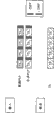
Figure 12 A shows the example of the structure of T2 frame to 12C.
Specifically, Figure 12 A shows in the situation that the structure of the T2 frame of T2 frame number P_I=1 and interval Ijump=1.
Due to P_I=1 in the structure at Figure 12 A, so form an interlacing frames by a T2 frame.In addition, due to interval Ijump=1, so relevant PLP is inserted in each T2 frame.In this example, because the unit of T2 frame is mutually the same with the unit of the TI piece that is formed by a plurality of FEC pieces, so, in the stage that the input of a T2 frame completes, carry out the time de-interweaving of being carried out by time de-interweaving device 22A and process and carry out TI and export.
Figure 12 B shows in the situation that the structure of the T2 frame of T2 frame number P_I=2 and interval Ijump=1.
In the structure of Figure 12 B, due to T2 frame number P_I=2, thus by two T2 frames, form an interlacing frames, and due to interval Ijump=1, so relevant PLP is inserted in each of T2 frame.In this example, due to two T2 frames, form the unit of TI pieces, so in the stage that the input of two continuous T 2 frames completes, TI output is processed and carried out in the time of implementation deinterleaving.
Figure 12 C shows in the situation that the structure of the T2 frame of T2 frame number P_I=2 and interval Ijump=2.
In the structure of Figure 12 C, due to T2 frame number P_I=2, thus by two T2 frames, form an interlacing frames, and, due to interval Ijump=2, so relevant PLP skips a T2 frame, insert.In this example, because two T2 frames that form interlacing frames do not occur continuously, so in the stage of two T2 frames that complete the intermittent input of input, TI output is processed and carried out in the time of implementation deinterleaving.
Attention: Figure 12 A is only example to the structure of the T2 frame shown in Figure 12 C, and the value of T2 frame number P_I and interval Ijump can be set arbitrarily.
These combinations of T2 frame number P_I in appointed information as above and interval Ijump are for synchronizeing between the T2 frame of setting up as mentioned above the TS bag be constructed to comprise public PLP and T2 frame that the TS that is constructed to comprise data PLP wraps.
By the way, by the method that is called the compensating delay method, send the data (that is, ofdm signal) that send from transmitting apparatus 2.According to this compensating delay method, transmitting apparatus 2 sides regularly postpone the transmission of one of data, make the reception of receiving equipment 1 side regularly can become mutually the same.Here, for convenience of description, at first with reference to Figure 13, describe the situation that compensating delay is invalid, then with reference to Figure 14, describe the effective situation of compensating delay.
Attention: in Figure 13 and Figure 14, the TS that shows public PLP at upside wraps the mode that is mapped to the T2 frame, and the TS that shows data PLP at downside wraps the mode that is mapped to the T2 frame.In addition, although in Figure 13 and Figure 14, take the T2 frame length as unit, only show the TS bag, reality also comprises above-mentioned sky bag except the TS bag.In addition, time orientation is from left to right direction in Figure 13 and Figure 14.This relation also with the explanation that provides hereinafter in several accompanying drawings of mentioning similar.
In addition, in the example of Figure 13 and Figure 14, suppose: as appointed information, the T2 frame of public PLP is arranged to T2 frame number P_I=2 and interval Ijump=2, the T2 frame of data PLP is arranged to T2 frame number P_I=1 and interval Ijump=1.In addition, error correction block 22 is exported public PLP and data PLP take the TI piece as unit as mentioned above, and TI output is corresponding to " TI output " in Figure 13 and Figure 14.Therefore, data corresponding with " TI output " and be imported into output I/F 23 with frame index F_i corresponding to T2 frame in Figure 13 and Figure 14.
With reference to Figure 13, because T2 frame number P_I and the interval Ijump of the T2 frame of the data PLP at the accompanying drawing downside is P_I=1 and Ijump=1, so in the stage that completes the data input of a T2 frame, time de-interweaving device 22A starts immediately TI output and simultaneously data is carried out to time de-interweaving.Specifically, if the data of T2 frame 0 are accumulated, TI piece 0 is output, and equally about T2 frame 1, T2 frame 2 ..., data, each when having completed the input of T2 frame, TI piece 1, TI piece 2 ... be output.
On the other hand, because T2 frame number P_I and the interval Ijump of the T2 frame of the public PLP of Figure 13 upside is P_I=2 and Ijump=2, so when frame index F_i is F_i=3, namely in the stage of the input that completes T2 frame 3, the data of the TI block unit that is formed by two T2 frames (comprising T2 frame 1 and T2 frame 3) are accumulated to allow to export from time de-interweaving device 22A.As a result, the TI piece 1 that is formed by T2 frame 1 and T2 frame 3 is exported by TI.
At this moment, because the TI piece 0 of data PLP and the TI piece 1 of public PLP belong to the needs Bao Qun that they is read synchronized with each other (namely in identical timing), so, in order to make the TI piece synchronized with each other, need to have the buffer of capacity of at least three T2 frames with the TI piece of delayed data PLP.
In other words, in the situation that compensation is invalid, in order between the T2 frame of public PLP and data PLP, to set up and synchronize, needs are used for the buffer of the data of maintenance take the T2 frame as unit.
On the other hand, in the effective situation of compensating delay as shown in figure 14, by transmitting apparatus 2 sides the TS packet delay of data PLP and three T2 frames (the 4[T2 frame]-the 1[T2 frame]=the 3[T2 frame]) the corresponding time period.
In this example, the TI piece 1 of the TI piece 3 of data PLP (being the TI output of the T2 frame 3 (F_i=3) of data PLP) and public PLP (being the TI output of T2 frame 1 (F_i=1) and the T2 frame 3 (F_i=3) of the public PLP) TI of carrying out synchronized with each other output.In addition, the T2 frame that is subordinated to the Bao Qun that need to read in identical timing obtains these TI pieces.
In this way, in the effective situation of compensating delay, due to the T2 frame of one of PLP, by transmitting apparatus 2 sides, postpone to set up synchronous between the T2 frame of public PLP and data PLP, so when carrying out TI while exporting, TI piece is synchronized with each other exports for these.As a result, eliminated the necessity to the sort buffer device of one of described T2 frame that is in leading state for delay of reference Figure 13.
In the effective situation of this compensating delay, as shown in figure 15, the TI piece 0 of TI piece 1 of public PLP etc. and data PLP, TI piece 1, TI piece 2, TI piece 3 etc. are input to output I/F 23 from error correction block 22 continuously, namely are input to synchronization detecting section 30.In addition, at this moment, due to the frame index F_i that has also inputted the T2 frame of distributing to PLP, so synchronization detecting section 30 uses the appointed information that comprises frame index F_i, T2 frame number P_I and interval Ijump to specify the combination of T2 frame synchronized with each other.
Specifically, when the combination of the T2 frame of having specified public PLP with the frame index F_i that meets expression formula given below (3) and data PLP, think and public PLP synchronized with each other and data PLP detected.
{floor(F_i_Common/(P_I×I_jump)_Common)+l}×
(P_I×I_jump)_Common
=={floor(F_i_Data/(P_I×I_jump)_Data)+l}×(P_I×I_jump)_Data
...(3)
Attention: in expression formula (3), in the situation that T2 frame number P_I ≠ 1, namely in the situation that form an interlacing frames by a plurality of T2 frames, adopt the frame index F_i that has relative low value in the frame index F_i of PLP.For example, in the situation that the public PLP of Figure 15, because TI piece 1 is formed by T2 frame 1 and T2 frame 3, so adopt the frame index F_i=1 with relative low value.
For example, although Figure 15 shows the situation that the T2 frame of public PLP and data PLP is synchronizeed with T2 frame 3, if but the frame index F_i=1 of public PLP (do not adopt F_i=3 but adopt the F_i=1 of relative low value), T2 frame number P_I=2 and interval Ijump=2 and frame index F_i=3, T2 frame number P_I=1 and interval Ijump=1 are obtained expression by the above-mentioned expression formula of substitution (3).
Left side=the floor (1/4+1) of expression formula (3) * 4=4
Right side=the floor (3/1+1) of expression formula (3) * 1=4
Therefore, when the frame index F_i of the T2 frame of public PLP and data PLP is equal to F_i=3, can think that these T2 frames 3 are synchronized with each other.In other words, in expression formula (3), when the last value of P_I * Ijump of public PLP and data PLP is equal to each other, think that these PLP are synchronized with each other.
Similarly, in the example of Figure 15, when the frame index F_i of the T2 of public PLP frame be F_i=5,9,13 ... the time, the F_i=7,11,15 of the T2 frame of it and data PLP ... meet the relation of expression formula (3).
After the combination of the T2 frame of specifying in the manner described above public PLP synchronized with each other and data PLP by synchronization detecting section 30, from the TTO that is added to the TS bag that forms T2 frame synchronized with each other, determine the poor TTO of TTO
Diff.Then, read control section 34 and move reading regularly of they between the TS of public PLP and data PLP bag, make the TS bag that reads public PLP synchronized with each other and data PLP.
By the way, if the TTO that obtains from the TS of public PLP bag is represented by TTO_Common and represented by TTO_Data from the TTO that the TS bag of data PLP obtains, the starting point of the time of the starting point of the time of TTO_Common and TTO_Data is inconsistent each other in some cases.
Between these starting points, occur that skew is because the frame index F_i of T2 frame synchronized with each other differs from one another.For example, in the situation that the frame index F_i of T2 frame synchronized with each other is consistent with each other as shown in figure 11, the starting point of the time of the TTO of T2 frame is mutually the same.Therefore, if only actually uses poor between the value of TTO, can set up synchronous between TTO.On the other hand, as shown in figure 16, in the situation that the frame index F_i of T2 frame synchronized with each other differs from one another, the starting point of the time of TTO_Common and the starting point of the time of TTO_Data are inconsistent each other.Therefore, need to correct the skew between these starting points.
By expression (4), determined to correct the poor TTO of TTO of this skew between starting point
Diff.
TTO
diff=TTO_Common-{TTO_Data+(F_i_Data-F_i_Common)
×T2_frame_length}
...(4)
Wherein, F_i_Data is the value of frame index F_i of the T2 frame of data PLP, and F_i_Common is the value of frame index F_i of the T2 frame of public PLP.In addition, T2_frame_length is take T[us] length of the T2 frame that represents as unit and be a kind of above-mentioned correction information.Therefore, by TTO
DiffCorrect the poor TTO of TTO of unit 51 executable expressions (4)
DiffCorrection process.
In expression formula (4), T2 frame length T2_frame_length multiply by poor between the frame index F_i of T2 frame of TTO_Common and TTO_Data, thereby increases a certain amount of to remove the amount of compensating delay.In other words, according to expression formula (4), the poor TTO of TTO is determined in the skew between the starting point of the time of having corrected TTO_Common and TTO_Data later
Diff.
Then, by the mobile TTO difference TTO according to determining as upper type of reading regularly of the bag of the TS by public PLP and data PLP
Diff, the TS bag of public PLP and data PLP is output synchronously with one another.
Therefore, even the frame index F_i of T2 frame synchronized with each other differs from one another, still can determine the poor TTO of TTO accurately
DiffAnd set up definitely synchronizeing between public PLP and data PLP.
Simultaneously, in the situation that insert as shown in figure 17 FEF (that is: the structure frame different from the structure of T2 frame), the length of FEF is also included within compensating delay.Therefore, similar with the situation of Figure 16, the starting point of the time of TTO_Common and the starting point of the time of TTO_Data are offset each other.In the example of Figure 17, FEF interval FEF_interval is FEF_interval=2, that is: the FEF of predetermined length is between T2 frame 1 and T2 frame 2 and between T2 frame 3 and T2 frame 4.In this example, when determining the poor TTO of TTO
DiffThe time, also must remove the length of FEF.
By expression (5), determined to correct the poor TTO of TTO of this skew between the starting point with FEF
Diff.
TTO
diff=TTO_Common-[TTO_Data+(F_i_Data-F_i_Common)
×T2_frame_length+{floor(F_i_Data/FEF_interval)
-floor(F_i_Common/FEF_interVal)}×FEF_length]
...(5)
Wherein, FEF_length is that unit is T[us] length and the FEF_interval of FEF be the number that is inserted in the T2 frame between FEF, and they belong to above-mentioned correction information.Specifically, by TTO
DiffCorrect the poor TTO of TTO in unit 51 executable expressions (5)
DiffCorrection process.
According to expression formula (5), T2 frame length T2_frame_length and be inserted in TTO_Common and the T2 frame of the frame index F_i of the T2 frame of TTO_Data between the difference that all multiply by between frame index F_i of the length FEF_length of FEF a certain amount of to increase, thereby remove the amount corresponding with the amount of compensating delay.In other words, think: in expression formula (5), after the starting point of the time of correcting TTO_Common and TTO_Data, determine the poor TTO of TTO
Diff.
Therefore, even the frame index F_i of T2 frame synchronized with each other differs from one another and inserted FEF, still can determine the poor TTO of TTO accurately
DiffAnd set up definitely synchronizeing between public PLP and data PLP.
TTO synchronously processes
Now, the flow chart description TTO with reference to Figure 18 synchronously processes.
Attention: in the description that provides with reference to Figure 18 hereinafter, suppose: the data of the form of the ofdm signal that sends from transmitting apparatus 2 send under the effective state of compensating delay.
At first, at step S11, T2 frame number P_I and the interval Ijump that provides from demodulation block 21 is provided appointed information acquiring unit 41.Then, at step S12, the frame index F_i that provides from error correction block 22 is provided appointed information acquiring unit 41.
At step S13, TTO synchronous detection unit 42 uses the appointed information (that is, T2 frame number P_I, interval Ijump and frame index F_i) of obtaining from appointed information acquiring unit 41 to start to detect T2 frame synchronized with each other.
Specifically, at step S14, T2 frame number P_I, the interval Ijump that TTO synchronous detection unit 42 will obtain and frame index F_i substitution expression formula (3), meet the combination of frame index F_i of the relation of expression formula (3) with appointment.Yet, if target frame index F_i does not obtain the identification result of T2 frame synchronized with each other and step S14, be "No", process and turn back to step S12.
Then, step S12 is repeated to obtain continuously the frame index F_i of next T2 frame to the processing of S14, until T2 frame synchronized with each other detected.Then, the value of frame index F_i is processed with the discriminating of the relation that repeats whether to meet expression formula (3) by continuous substitution expression formula (3).
Then, the relation of IF expression (3) is met and has determined to detect T2 frame synchronized with each other at step S14, in step S15, reads the TTO that control section 34 obtains the TS bag that is added to the public PLP that forms T2 frame synchronized with each other and data PLP.
At step S16, TTO synchronous detection unit 42 differentiates whether the frame index F_i of T2 frame synchronized with each other is consistent with each other.If F_i is consistent with each other at step S16 judgment frame index, due to not skew between the starting point of the time at TTO, so in step S21, read control section 34, according to the difference between the TTO that obtains, determine the poor TTO of TTO
Diff.In brief, in this example, TTO
DiffCorrect unit 51 and do not carry out the poor TTO of TTO
DiffCorrection process.
On the other hand, if in step S16, determine that frame index F_i differs from one another, because needs are carried out the poor TTO of TTO
DiffCorrection process, so in step S17 TTO
DiffCorrect unit 51 the correction information that provides from demodulation block 21 is provided.This correction information is for correcting the poor TTO of TTO
Diff(for example, T2 frame length T2_frame_length as above, FEF length FEF_length or FEF interval FEF_interval).
In step S18, TTO
DiffCorrect unit 51 and differentiate based on the correction information of obtaining whether FEF is inserted in the T2 frame.If in step S18, determine not insert FEF, TTO in step S19
DiffCorrect unit 51 based on frame index F_i between poor corresponding amount correction TTO_Common and the skew between the starting point of time of TTO_Data.Then, TTO in step S21
DiffCorrect unit 51 and determine the poor TTO of TTO
Diff.
Specifically, in this example, TTO
DiffCorrect unit 51 and will correct the value substitution expression formula (4) of information (comprising TTO_Common, TTO_Data, F_i_data, F_i_Common and T2 frame length T2_frame_length) to determine the poor TTO of TTO
Diff, as hereinbefore with reference to as described in Figure 16.
On the other hand, if differentiate and inserted FEF, TTO in step S20 in step S17
DiffCorrect unit 51 according to the skew between the starting point of the time of the poor corresponding amount correction TTO_Common between the FEF with frame index F_i and insertion and TTO_Data.Then, TTO in step S21
DiffCorrect unit 51 and determine the poor TTO of TTO
Diff.
Specifically, in this example, TTO
DiffCorrect unit 51 and will correct the information value substitution expression formula (5) of (comprising TTO_Common, TTO_Data, F_i_data, F_i_Common, T2 frame length T2_frame_length, FEF interval FEF_interval and FEF length FEF_length), to determine the poor TTO of TTO
Diff, as hereinbefore with reference to as described in Figure 17.
In this way, as the poor TTO of TTO
DiffComputational methods, determine the poor TTO of TTO
DiffAnd do not relate to correction the first method, by expression formula (4), correct and determine the poor TTO of TTO
DiffThe second method and by expression formula (5), correct and determine the poor TTO of TTO
DiffThird method can use.Therefore, utilize one of first to the 3rd computational methods according to the existence of the FEF of the consistency of frame index F_i and insertion or do not exist and determine the poor TTO of TTO
Diff.
Then, in step S22, read the TS bag that control section 34 reads combination, so that reading regularly of the TS of public PLP and data PLP bag is mobile by the poor TTO of the definite TTO of one of first to the 3rd computational methods
Diff, synchronous to carry out TTO.
TTO is synchronous and by after reading control section 34 and starting reading of the TS bag synchronous according to TTO carrying out, and the synchronous processing of the TTO of Figure 18 finishes.
Owing to by TTO synchronous detection unit 42, using appointed information (for example frame index F_i, T2 frame number P_I and interval Ijump) to specify the combination of the T2 frame that the TS bag by public PLP synchronized with each other and data PLP forms as mentioned above, so detect TTO synchronous of the TS bag that is added to the T2 frame that forms appointment.Then, by reading control section 34, utilize the poor TTO of TTO that obtains from TTO synchronized with each other
DiffRead the TS bag of public PLP synchronized with each other and data PLP.Therefore, even, in the situation that to have inserted the T2 frame of public PLP and data PLP not always fixing, can specify the T2 frame that has inserted relevant PLP.Therefore, can set up definitely synchronizeing between public PLP and data PLP.
In addition, owing to passing through TTO
DiffSkew between the starting point of the time of correction unit 51 correction TTO_Common and TTO_Data, so, even even the frame index F_i of T2 frame synchronized with each other differs from one another or inserted FEF, still can determine the poor TTO of TTO accurately
Diff.Therefore, can set up definitely synchronizeing between public PLP and data PLP.The example of the structure of receiving system
The structure of receiving system is described to Figure 21 referring now to Figure 19.
Figure 19 shows the example of the structure of the first mode of applying receiving system of the present invention.
With reference to Figure 19, receiving system comprises obtains part 201, transmission line decoding processing section 202 and information source decoding processing section 203.
Obtain part 201 and by transmission line (for example, terrestrial digital broadcast, satellite broadcasting, CATV (cable TV) network, the Internet or more unshowned other network), obtain the ofdm signal of the M-PLP mode of DVB-T2.Obtain the ofdm signal that part 201 will obtain and offer transmission line decoding processing section 202.
If for example from broadcasting station by surface wave, satellite ripple, catv network etc. broadcast ofdm signal,, with shown in Figure 2 to obtain part 12 similar, obtain part 201 and formed by tuner, STB etc.On the other hand, if for example equally with the situation of IPTV (IPTV) by multicast, from the WEB server, send ofdm signal, obtain part 201 and formed by the network I/F of for example NIC (network interface unit).
If for example from broadcasting station by surface wave, satellite ripple, catv network etc., broadcast ofdm signal, for example obtain part 201 and receive a plurality of ofdm signals that send by a plurality of transmission lines from a plurality of transmitting apparatus.As a result, receive the single ofdm signal of a plurality of ofdm signals as combination.
Transmission line decoding processing section 202 is carried out the transmission lines decoding and is processed, and the processing that comprises at least from by obtaining the ofdm signal decoding PLP that part 201 obtains by transmission line is processed in this transmission line decoding.Then, will decode and process the signal that obtains and offer the information source processing section 203 of decoding by transmission line in transmission line decoding processing section 202.
Specifically, the ofdm signal of the public PLP definition M-PLP mode that forms due to a plurality of data PLP by consisting of remaining bag when being extracted as the total bag of all a plurality of TS from each TS with by described public bag, so processing and output gained signal to ofdm signal decoding PLP (packet sequence) are for example carried out in transmission line decoding processing section 202.
In addition, by obtaining the ofdm signal that part 201 obtains by transmission line, be in the state that distortion occurs due to the impact that is subject to transmission line property, and transmission line decoding processing section 202 is carried out decoding to this ofdm signal and is processed (for example comprise transmission line estimation, channel estimating, phase estimation, etc.).
In addition, the transmission line decoding is processed and is comprised the processing of correcting the mistake that is caused by transmission line etc.For example, as error correction coding, LDPC code, reed solomon coding etc. are available.
203 pairs of processing sections of information source decoding have been carried out the signal execution information source decoding of transmission line decoding processing and have been processed, and this information source decoding processing comprises the processing that compressed information is de-compressed into to raw information at least.
Specifically, by obtaining ofdm signal that part 201 obtains by transmission line, sometimes be in for the data volume that reduces image as information, sound etc. and the state of the compressed encoding of compressed information.In this example, 203 pairs of processing sections of information source decoding have been carried out signal that the transmission line decoding processes and are carried out the information source decoding and process (for example, compressed information being de-compressed into to the processing of raw information etc.).
Attention: if by the form of obtaining ofdm signal that part 201 obtains by transmission line and be not in compressed encoding, the processing that compressed information is de-compressed into to raw information is not carried out in information source decoding processing section 203.
Here, decompression can be for example mpeg decode.In addition, except decompression, the transmission line decoding is processed and is sometimes also comprised deciphering (descrambling) etc.
In the receiving system that builds in the above described manner, obtain part 201 and obtain by the market demand compressed encoding to for example image and sound (for example mpeg encoded) and also apply the ofdm signal according to the M-PLP mode that error correction coding obtains by transmission line.Obtain the ofdm signal that part 201 will obtain and offer transmission line decoding processing section 202.Attention: at this moment, occur in the impact owing to being subject to transmission line property to obtain ofdm signal under the state of distortion.
The processing similar to the processing of transmission line shown in Figure 2 decoding processing section 13 carried out in transmission line decoding processing section 202, as the transmission line decoding of the ofdm signal for from obtaining part 201, processes.To decode and process the signal that obtains and offer the information source processing section 203 of decoding by transmission line in transmission line decoding processing section 202.
Information source decoding processing section 203 is carried out with the processing of decoder 14 shown in Figure 2 and is similarly processed as the information source decoding of the signal for from transmission line decoding processing section 202 and process.203 outputs of information source decoding processing section are decoded and are processed image or the sound that obtains by information source.
This receiving system of above-mentioned Figure 19 for example can be applied to TV tuner of receiving television broadcasting (for example digital broadcasting) etc.
Attention: each that obtain in part 201, transmission line decoding processing section 202 and information source decoding processing section 203 all can be configured to single autonomous device or hardware device (for example, IC (integrated circuit) or software module).
In addition, can construct by different way and obtain part 201, transmission line decoding processing section 202 and information source decoding processing section 203.For example, obtain the group of group, transmission line decoding processing section 202 and the information source decoding processing section 203 of part 201 and transmission line decoding processing section 202, or the group of obtaining part 201, transmission line decoding processing section 202 and information source decoding processing section 203 can be configured to single autonomous device.
Figure 20 shows the example of the structure of the second pattern of applying receiving system of the present invention.
Receiving system shown in Figure 20 is included in above the common parts of the receiving system of describing with reference to Figure 19, and has saved in this article being repeated in this description of common parts for fear of redundancy.
With reference to Figure 20, the something in common of shown receiving system and receiving system describing above with reference to Figure 19 is that it comprises and obtains part 201, transmission line decoding processing section 202 and information source decoding processing section 203, and the difference of the receiving system of it and Figure 19 is also to comprise output 211.
The receiving system of above-mentioned Figure 20 for example can be applied to for receive television set as the television broadcasting of digital broadcasting, be used to the radio receiver that receives radio broadcasting, etc.
Attention: if, by the state that obtains ofdm signal that part 201 obtains and be not in compressed encoding, offer output 211 from the signal of transmission line decoding processing section 202 outputs.
Figure 21 shows the example of the structure of the three-mode of applying receiving system of the present invention.
Receiving system shown in Figure 21 comprises the parts common with the receiving system of describing with reference to Figure 19 hereinbefore, and has saved in this article being repeated in this description of common parts for fear of redundancy.
With reference to Figure 21, the similarity of shown receiving system and the receiving system of Figure 19 is that it comprises and obtains part 201 and transmission line decoding processing section 202.
Yet note: the receiving system of Figure 21 and the difference of Figure 19 are that it does not comprise information source decoding processing section 203 but comprises recording section 221.
Receiving system with Figure 21 of said structure can be applied to the register for record television broadcast etc.
The receiving system of attention: Figure 21 can also comprise information source decoding processing section 203, make at the signal (that is the image or the sound that, obtain by decoding) that is undertaken after the information source decoding is processed by information source decoding processing section 203 and can carry out record by recording section 221.
Computer of the present invention is described
By the way, although above-mentioned a series of processing can, by hardware implement, also can be carried out by software.When by software, carrying out this series of processes, form the installation of this software in computer.Computer in this example comprise the computer that is incorporated in specialized hardware, the general purpose personal computer that can carry out various functions by various programs are installed, etc.
Figure 22 shows the example of carrying out the hardware structure of computer of above-mentioned a series of processing according to program.
With reference to Figure 22, shown in computer in, CPU (CPU) 401, read-only memory (ROM) 402 and random access storage device (RAM) 403 are connected to each other by bus 404.
In addition, input/output interface 405 is connected to bus 404.Importation 406, output 407, storage area 408 and communications portion 409 and driver 410 are connected to input/output interface 405.
In the computer of constructing in the above described manner, CPU 401 is loaded in RAM 403 and carries out this program to carry out above-mentioned a series of processing by the program that input/output interface 405 and bus 404 will for example be stored in storage area 408.
The program of particularly being carried out by CPU 401 by computer can be recorded on removable medium 411 and as removable medium 411 (for example, encapsulation medium etc.) and provide.In addition, can pass through wired or wireless transmission medium (for example, local area network (LAN), the Internet or digital broadcasting) this program is provided.
In computer, can removable medium 411 be loaded in driver 410 installation in storage area 408 by input/output interface 405.In addition, this program can be received and be installed in storage area 408 by wired or wireless transmission medium by communications portion 409.Perhaps, program can be arranged in ROM 402 or storage area 408 in advance.
Attention: in this manual, description be recorded in recording medium or on program step can but must according to time series, not process according to described order, and comprise parallel or independently carry out and less than the processing of processing according to time series.
In addition, in this manual, the whole equipment that term " system " is comprised of a plurality of devices or equipment for expression.
Although used particular term to describe the preferred embodiments of the present invention, this description is only schematic purpose, and should be understood that in the situation that do not break away from the spirit or scope of claim and can change and change.
The application comprises the theme relevant with disclosed theme in the Japanese priority patent application JP 2010-000920 that is to be submitted on January 6th, 2010 Japan Office, and the full content of this Japanese priority patent application is incorporated herein by reference.
Claims (10)
1. receiving equipment comprises:
Receiving system, reception is by modulating to the first frame and the second frame the orthogonal frequency division multiplex OFDM signal that obtains, described the first frame is constructed to comprise the bag by the public packet sequence that forms for the total bag of a plurality of stream, and described the second frame is constructed to comprise by being described a plurality of stream bag of the sequence of data packet that forms of exclusive bag respectively;
Deriving means, obtain and be used to specify the appointed information of carrying out the combination of the first frame of demodulation acquisition and the second frame by the ofdm signal to receiving; And
Checkout gear, detect based on the appointed information of obtaining designated the combination of bag and the bag of the sequence of data packet that forms the second frame of combination, public packet sequence that form the first frame,
Wherein, appointed information comprises that expression is inserted into the information of the distance in the first frame and represents that described sequence of data packet inserts the information of the distance in the second frame with respect to information, the described public packet sequence of expression of the number of the first frame as the predetermined frame of benchmark and the second frame; And
Described checkout gear is specified the first frame and the second frame that forms the combination corresponding with the information of expression number and distance.
2. according to claim 1 receiving equipment, also comprise reading device, for using poor information to read public packet sequence synchronized with each other and the bag of sequence of data packet, wherein, described poor information is be added to the information that forms the first specified frame and the bag of the second frame and the timing that these bags are read in expression poor.
3. according to claim 2 receiving equipment, wherein, appointed information comprises that expression distributes to each the information of frame index of the first frame and the second frame, and
Described receiving equipment also comprises correcting device, in the situation that the information of the frame index of expression the first frame and the second frame differs from one another, according to the frame length of the length that represents the first frame and the second frame, corrects described poor information.
4. according to claim 2 receiving equipment, wherein, appointed information comprises that expression distributes to the information of the frame index of the first frame and the second frame, and
Described receiving equipment also comprises correcting device, for in the situation that the information of expression the first frame and the frame index of the second frame differ from one another and inserted structure three frame different with the second frame from the first frame, according to the first frame length of the length of expression the first frame and the second frame, represent the 3rd frame length the second frame length and configure the described poor information of distance correction of the 3rd frame.
5. according to claim 1 receiving equipment, wherein, public packet sequence and sequence of data packet are respectively common physical layer pipeline PLP and the data physical layer pipe PLP that generates from a plurality of stream according to many physical layer pipe M-PLP mode of digital video broadcast terrestrial DVB-T.2.
6. method of reseptance comprises the following steps of being carried out by receiving equipment:
Reception is by modulating to the first frame and the second frame the orthogonal frequency division multiplex OFDM signal that obtains, described the first frame is constructed to comprise the bag by the public packet sequence that forms for the total bag of a plurality of stream, and described the second frame is constructed to comprise by being a plurality of stream bag of the sequence of data packet that forms of exclusive bag respectively;
Obtain and be used to specify the appointed information of carrying out the combination of the first frame of demodulation acquisition and the second frame by the ofdm signal to receiving; And
Detection based on the appointed information of obtaining designated the combination of bag and the bag of the sequence of data packet that forms the second frame of combination, public packet sequence that form the first frame,
Wherein, appointed information comprises that expression is inserted into the information of the distance in the first frame and represents that described sequence of data packet inserts the information of the distance in the second frame with respect to information, the described public packet sequence of expression of the number of the first frame as the predetermined frame of benchmark and the second frame; And
Detecting step is specified the first frame and the second frame that forms the combination corresponding with the information of expression number and distance.
7. receiving system comprises:
The first deriving means, for by transmission line, obtaining by the first frame and the second frame are modulated to the orthogonal frequency division multiplex OFDM signal that obtains, described the first frame is constructed to comprise the bag by the public packet sequence that forms for the total bag of a plurality of stream, and described the second frame is constructed to comprise by being a plurality of stream bag of the sequence of data packet that forms of exclusive bag respectively; With
Transmission line decoding processing section, be suitable for that the ofdm signal that obtains via transmission line is carried out to the transmission line decoding and process, and described transmission line decoding is processed the decoding that comprises at least packet sequence and processed;
Described transmission line decoding processing section comprises:
The second deriving means, be used to specify the appointed information of carrying out the combination of the first frame of demodulation acquisition and the second frame by the ofdm signal to obtaining via transmission line be used to obtaining, and
Checkout gear, detect based on the appointed information of obtaining designated the combination of bag and the bag of the sequence of data packet that forms the second frame of combination, public packet sequence that form the first frame,
Wherein, appointed information comprises that expression is inserted into the information of the distance in the first frame and represents that described sequence of data packet inserts the information of the distance in the second frame with respect to information, the described public packet sequence of expression of the number of the first frame as the predetermined frame of benchmark and the second frame; And
Described checkout gear is specified the first frame and the second frame that forms the combination corresponding with the information of expression number and distance.
8. receiving system comprises:
Transmission line decoding processing section, be suitable for via transmission line, obtaining and carrying out the transmission line decoding and process by the first frame and the second frame being modulated to the orthogonal frequency division multiplex OFDM signal that obtains, described the first frame is constructed to comprise the bag by the public packet sequence that forms for the total bag of a plurality of stream, described the second frame is constructed to comprise by being a plurality of stream bag of the sequence of data packet that forms of exclusive bag respectively, wherein, the decoding processing that comprises at least packet sequence is processed in described transmission line decoding; And
Information source decoding processing section, be suitable for that the signal of having carried out transmission line decoding processing is carried out to the information source decoding and process, and wherein, described information source decoding processing comprises the processing that compressed information is de-compressed into to raw information at least;
Described transmission line decoding processing section comprises:
Deriving means, be used to specify the appointed information of carrying out the combination of the first frame of demodulation acquisition and the second frame by the ofdm signal to obtaining via transmission line be used to obtaining, and
Checkout gear, detect based on the appointed information of obtaining designated the combination of bag and the bag of the sequence of data packet that forms the second frame of combination, public packet sequence that form the first frame,
Wherein, appointed information comprises that expression is inserted into the information of the distance in the first frame and represents that described sequence of data packet inserts the information of the distance in the second frame with respect to information, the described public packet sequence of expression of the number of the first frame as the predetermined frame of benchmark and the second frame; And
Described checkout gear is specified the first frame and the second frame that forms the combination corresponding with the information of expression number and distance.
9. receiving system comprises:
Transmission line decoding processing section, be suitable for via transmission line, obtaining and carrying out the transmission line decoding and process by the first frame and the second frame being modulated to the orthogonal frequency division multiplex OFDM signal that obtains, described the first frame is constructed to comprise the bag by the public packet sequence that forms for the total bag of a plurality of stream, described the second frame is constructed to comprise by being a plurality of stream bag of the sequence of data packet that forms of exclusive bag respectively, wherein, the decoding processing that comprises at least packet sequence is processed in described transmission line decoding; And
Output, be suitable for based on having carried out signal output image or sound that the transmission line decoding is processed;
Described transmission line decoding processing section comprises:
Deriving means, be used to specify the appointed information of carrying out the combination of the first frame of demodulation acquisition and the second frame by the ofdm signal to obtaining via transmission line be used to obtaining, and
Checkout gear, detect based on the appointed information of obtaining designated the combination of bag and the bag of the sequence of data packet that forms the second frame of combination, public packet sequence that form the first frame,
Wherein, appointed information comprises that expression is inserted into the information of the distance in the first frame and represents that described sequence of data packet inserts the information of the distance in the second frame with respect to information, the described public packet sequence of expression of the number of the first frame as the predetermined frame of benchmark and the second frame; And
Described checkout gear is specified the first frame and the second frame that forms the combination corresponding with the information of expression number and distance.
10. receiving system comprises:
Transmission line decoding processing section, be suitable for via transmission line, obtaining and carrying out the transmission line decoding and process by the first frame and the second frame being modulated to the orthogonal frequency division multiplex OFDM signal that obtains, described the first frame is constructed to comprise the bag by the public packet sequence that forms for the total bag of a plurality of stream, described the second frame is constructed to comprise that described transmission line decoding is processed the decoding that comprises at least packet sequence and processed by being a plurality of stream bag of the sequence of data packet that forms of exclusive bag respectively; And
Recording section, be suitable for recording the signal of having carried out transmission line decoding processing;
Described transmission line decoding processing section comprises:
Deriving means, be used to specify the appointed information of carrying out the combination of the first frame of demodulation acquisition and the second frame by the ofdm signal to obtaining via transmission line be used to obtaining, and
Checkout gear, detect based on the appointed information of obtaining designated the combination of bag and the bag of the sequence of data packet that forms the second frame of combination, public packet sequence that form the first frame,
Wherein, appointed information comprises that expression is inserted into the information of the distance in the first frame and represents that described sequence of data packet inserts the information of the distance in the second frame with respect to information, the described public packet sequence of expression of the number of the first frame as the predetermined frame of benchmark and the second frame; And
Described checkout gear is specified the first frame and the second frame that forms the combination corresponding with the information of expression number and distance.
Applications Claiming Priority (2)
| Application Number | Priority Date | Filing Date | Title |
|---|---|---|---|
| JP2010000920A JP5483082B2 (en) | 2010-01-06 | 2010-01-06 | Receiving apparatus and method, program, and receiving system |
| JP2010-000920 | 2010-01-06 |
Publications (2)
| Publication Number | Publication Date |
|---|---|
| CN102118341A CN102118341A (en) | 2011-07-06 |
| CN102118341B true CN102118341B (en) | 2013-11-20 |
Family
ID=43899666
Family Applications (1)
| Application Number | Title | Priority Date | Filing Date |
|---|---|---|---|
| CN2010106117453A Active CN102118341B (en) | 2010-01-06 | 2010-12-29 | Reception apparatus and method, program and reception system |
Country Status (6)
| Country | Link |
|---|---|
| US (1) | US8520754B2 (en) |
| EP (1) | EP2343860B1 (en) |
| JP (1) | JP5483082B2 (en) |
| CN (1) | CN102118341B (en) |
| ES (1) | ES2601857T3 (en) |
| TW (1) | TWI465082B (en) |
Families Citing this family (11)
| Publication number | Priority date | Publication date | Assignee | Title |
|---|---|---|---|---|
| CA2789648C (en) * | 2010-02-11 | 2018-08-21 | Sony Corporation | Mapping apparatus and method for transmission of data in a multi-carrier broadcast system |
| US10424274B2 (en) * | 2010-11-24 | 2019-09-24 | Ati Technologies Ulc | Method and apparatus for providing temporal image processing using multi-stream field information |
| JP2012222604A (en) * | 2011-04-08 | 2012-11-12 | Sony Corp | Data readout device, data readout method, and program |
| KR102097450B1 (en) * | 2013-03-22 | 2020-04-06 | 삼성전자주식회사 | A method and apparatus for decreasing of peak-to-average power ratio in a radio communication system based on single carrier-freqeuncy division multiple access |
| ITTO20130630A1 (en) * | 2013-07-25 | 2015-01-26 | Rai Radiotelevisione Italiana | SYSTEM, DECODER AND METHOD FOR SATELLITE SIGNAL TRANSMISSION |
| ITTO20130729A1 (en) * | 2013-09-09 | 2015-03-10 | Rai Radiotelevisione Italiana | METHOD AND SYSTEM FOR SATELLITE SIGNAL TRANSMISSION AND ITS RECEIVER |
| KR102120155B1 (en) * | 2013-10-04 | 2020-06-08 | 한국전자통신연구원 | Apparatus and method for transmitting and receiving 3dtv broadcasting of mobile hybrid type |
| MX355585B (en) * | 2013-11-13 | 2018-04-24 | Lg Electronics Inc | Apparatus for transmitting broadcast signals, apparatus for receiving broadcast signals, method for transmitting broadcast signals and method for receiving broadcast signals. |
| WO2015178690A1 (en) * | 2014-05-21 | 2015-11-26 | 엘지전자 주식회사 | Broadcast signal transmitting/receiving method and device |
| CN106303580A (en) * | 2015-07-08 | 2017-01-04 | 中国科学院上海高等研究院 | A kind of TS streaming method and system |
| US9800438B1 (en) * | 2016-10-25 | 2017-10-24 | Xilinx, Inc. | Built-in eye scan for ADC-based receiver |
Citations (2)
| Publication number | Priority date | Publication date | Assignee | Title |
|---|---|---|---|---|
| CN1723704A (en) * | 2003-03-19 | 2006-01-18 | 松下电器产业株式会社 | Data processing device |
| CN1788443A (en) * | 2003-07-29 | 2006-06-14 | 富士通株式会社 | Pilot multiplexing method and transmission/reception device in OFDM system |
Family Cites Families (7)
| Publication number | Priority date | Publication date | Assignee | Title |
|---|---|---|---|---|
| US7103025B1 (en) * | 2001-04-19 | 2006-09-05 | Cisco Technology, Inc. | Method and system for efficient utilization of transmission resources in a wireless network |
| JP2006157278A (en) * | 2004-11-26 | 2006-06-15 | Mitsubishi Electric Corp | Information distribution system |
| JP5032179B2 (en) * | 2007-03-30 | 2012-09-26 | 株式会社東芝 | Stream reproducing apparatus and media data decoding method |
| EP2186229B1 (en) * | 2007-09-05 | 2019-09-25 | Nokia Technologies Oy | Method and system to enable simultaneous reception of plurality of services in dvb systems |
| KR100937429B1 (en) * | 2008-02-04 | 2010-01-18 | 엘지전자 주식회사 | Method of transmitting and receiving a signal and apparatus thereof |
| US8819749B2 (en) * | 2008-06-11 | 2014-08-26 | Koninklijke Philips B.V. | Synchronization of media stream components |
| JP5245564B2 (en) | 2008-06-20 | 2013-07-24 | 日産自動車株式会社 | Vehicle braking force control device |
-
2010
- 2010-01-06 JP JP2010000920A patent/JP5483082B2/en not_active Expired - Fee Related
- 2010-12-01 TW TW099141755A patent/TWI465082B/en active
- 2010-12-02 US US12/958,729 patent/US8520754B2/en not_active Expired - Fee Related
- 2010-12-15 ES ES10195140.8T patent/ES2601857T3/en active Active
- 2010-12-15 EP EP10195140.8A patent/EP2343860B1/en active Active
- 2010-12-29 CN CN2010106117453A patent/CN102118341B/en active Active
Patent Citations (2)
| Publication number | Priority date | Publication date | Assignee | Title |
|---|---|---|---|---|
| CN1723704A (en) * | 2003-03-19 | 2006-01-18 | 松下电器产业株式会社 | Data processing device |
| CN1788443A (en) * | 2003-07-29 | 2006-06-14 | 富士通株式会社 | Pilot multiplexing method and transmission/reception device in OFDM system |
Non-Patent Citations (2)
| Title |
|---|
| 《Frame structure channel coding and modulation for a second generation digital terrestrial television broadcasting system》;DVB project;《DVB Document A122r1》;20090915;C.1.1段,图C.2 * |
| DVB project.《Frame structure channel coding and modulation for a second generation digital terrestrial television broadcasting system》.《DVB Document A122r1》.2009, |
Also Published As
| Publication number | Publication date |
|---|---|
| JP2011142422A (en) | 2011-07-21 |
| CN102118341A (en) | 2011-07-06 |
| ES2601857T3 (en) | 2017-02-16 |
| EP2343860A2 (en) | 2011-07-13 |
| JP5483082B2 (en) | 2014-05-07 |
| TW201132066A (en) | 2011-09-16 |
| EP2343860A3 (en) | 2012-04-04 |
| TWI465082B (en) | 2014-12-11 |
| US20110164706A1 (en) | 2011-07-07 |
| EP2343860B1 (en) | 2016-10-12 |
| US8520754B2 (en) | 2013-08-27 |
Similar Documents
| Publication | Publication Date | Title |
|---|---|---|
| CN102118341B (en) | Reception apparatus and method, program and reception system | |
| CN102118242B (en) | Reception apparatus and method, program and reception system | |
| US11696000B2 (en) | Method for transmitting broadcast signals and method for receiving broadcast signals | |
| EP2302848B1 (en) | Receiving apparatus for output streams recombination in DVB-T2 | |
| EP2696580B1 (en) | Data retrieval device, data retrieval method, and program | |
| CN102118342B (en) | Reception apparatus and method, program and reception system | |
| US20100290459A1 (en) | Transmission apparatus and method for packet data of variable length, and receiving apparatus | |
| CA2644340A1 (en) | Digital broadcasting system and data processing method thereof |
Legal Events
| Date | Code | Title | Description |
|---|---|---|---|
| C06 | Publication | ||
| PB01 | Publication | ||
| C10 | Entry into substantive examination | ||
| SE01 | Entry into force of request for substantive examination | ||
| C14 | Grant of patent or utility model | ||
| GR01 | Patent grant |