JP4491673B2 - Control booster - Google Patents
Control booster Download PDFInfo
- Publication number
- JP4491673B2 JP4491673B2 JP2000099506A JP2000099506A JP4491673B2 JP 4491673 B2 JP4491673 B2 JP 4491673B2 JP 2000099506 A JP2000099506 A JP 2000099506A JP 2000099506 A JP2000099506 A JP 2000099506A JP 4491673 B2 JP4491673 B2 JP 4491673B2
- Authority
- JP
- Japan
- Prior art keywords
- switch
- valve body
- rod
- pressure chamber
- plunger
- Prior art date
- Legal status (The legal status is an assumption and is not a legal conclusion. Google has not performed a legal analysis and makes no representation as to the accuracy of the status listed.)
- Expired - Lifetime
Links
Images


Classifications
-
- B—PERFORMING OPERATIONS; TRANSPORTING
- B60—VEHICLES IN GENERAL
- B60T—VEHICLE BRAKE CONTROL SYSTEMS OR PARTS THEREOF; BRAKE CONTROL SYSTEMS OR PARTS THEREOF, IN GENERAL; ARRANGEMENT OF BRAKING ELEMENTS ON VEHICLES IN GENERAL; PORTABLE DEVICES FOR PREVENTING UNWANTED MOVEMENT OF VEHICLES; VEHICLE MODIFICATIONS TO FACILITATE COOLING OF BRAKES
- B60T13/00—Transmitting braking action from initiating means to ultimate brake actuator with power assistance or drive; Brake systems incorporating such transmitting means, e.g. air-pressure brake systems
- B60T13/10—Transmitting braking action from initiating means to ultimate brake actuator with power assistance or drive; Brake systems incorporating such transmitting means, e.g. air-pressure brake systems with fluid assistance, drive, or release
- B60T13/66—Electrical control in fluid-pressure brake systems
- B60T13/72—Electrical control in fluid-pressure brake systems in vacuum systems or vacuum booster units
-
- B—PERFORMING OPERATIONS; TRANSPORTING
- B60—VEHICLES IN GENERAL
- B60T—VEHICLE BRAKE CONTROL SYSTEMS OR PARTS THEREOF; BRAKE CONTROL SYSTEMS OR PARTS THEREOF, IN GENERAL; ARRANGEMENT OF BRAKING ELEMENTS ON VEHICLES IN GENERAL; PORTABLE DEVICES FOR PREVENTING UNWANTED MOVEMENT OF VEHICLES; VEHICLE MODIFICATIONS TO FACILITATE COOLING OF BRAKES
- B60T7/00—Brake-action initiating means
- B60T7/12—Brake-action initiating means for automatic initiation; for initiation not subject to will of driver or passenger
Description
【0001】
【発明の属する技術分野】
本発明は、大気弁または真空弁を電磁的に作動する自動ブレーキ機能を有する制御型のブースタに関するものである。
【0002】
【従来の技術】
従来のこの種の制御ブースタの一例として、ハウジング内を定圧室と変圧室とに画成するパワーピストンと、該パワーピストンに支持されたバルブボディ内に設けられブレーキペダルに連動する入力ロッドに連結されたプランジャの移動により前記変圧室への作動流体の供給を制御する弁機構と、前記入力ロッドの作動とは別に前記弁機構を作動する可動子を有する電磁付勢手段と、電力源に接続され電力の供給を受けて前記プランジャを作動させる電磁ソレノイドと、前記パワーピストンに取り付けて前記定圧室に設置されたスイッチとを備え、前記入力ロッドと連動して軸方向に移動し該入力ロッドが前記パワーピストンに対して相対的に所定量移動した時にスイッチを作動させるスイッチロッドを有する制御ブースタがある。
そして、この制御ブースタでは、ブレーキペダル操作による変圧室と定圧室との間に生じる差圧を利用してブレーキ力を発生させる(以下、便宜上、ペダル操作ブレーキ作動という。)と共に、ブレーキペダル(入力ロッド)の作動とは別に電磁付勢手段を作動することにより前記変圧室と定圧室との間の差圧を発生させてブレーキ力を発生させる(以下、便宜上、自動ブレーキ作動という。)ようにしている。
【0003】
【発明が解決しようとする課題】
ところで、上述した従来技術の制御ブースタでは、スイッチロッドがプランジャと連結あるいは係合されているため、プランジャの移動量がそのままスイッチ(スイッチの固定接点)に伝達され、無理にスイッチが操作されて破損してしまうおそれがあった。
また、制御ブースタでは、自動ブレーキ作動時に、ペダル操作ブレーキ作動を行うとき、自動ブレーキ作動を中止することが望まれる。そして、この要望に応えるために、上述した従来技術のスイッチを、自動ブレーキ中におけるペダル操作ブレーキ作動の検出に利用するように構成しても、前記従来技術のスイッチでは、上述したようにプランジャの相対移動量がそのままスイッチに伝達されて破損してしまうおそれがあり、上記要望を適切には果たすことができないというのが実情である。
また、従来技術の他の例として、特表平10−505041号公報に示す制御ブースタがある。この制御ブースタでは、スイッチを変圧室に配置しており、例えばブレーキペダルによるブレーキ操作毎にスイッチが大気圧に曝され、スイッチにかかる圧力が頻繁に変化してしまうことになる。
【0004】
本発明は、上記事情に鑑みてなされたもので、自動ブレーキ中におけるペダル操作ブレーキ作動の検出を適切に行うことができる制御ブースタを提供することを目的とする。
また、本発明の他の目的は、スイッチに作用する圧力変化を小さくすることにある。
【0005】
【課題を解決するための手段】
請求項1記載の発明は、ハウジング内を定圧室と変圧室とに画成するパワーピストンと、該パワーピストンに支持されたバルブボディ内に設けられブレーキペダルに連動する入力ロッドに連結されたプランジャの移動により前記変圧室への作動流体の供給を制御する弁機構と、前記入力ロッドの作動とは別に前記弁機構を作動する可動子を有する電磁付勢手段と、を備え、前記弁機構の作動に基づく前記変圧室と前記定圧室との間に発生した差圧によって前記パワーピストンに生じた推力を出力する制御ブースタであって、
前記入力ロッドの前記バルブボディに対する相対移動を検出するスイッチと、該スイッチを作動させるスイッチ操作ロッドと、該スイッチ操作ロッドを前記スイッチの接点稼働子押し込み方向側に付勢するスイッチ用バネと、を備え、前記スイッチ操作ロッドは、前記入力ロッドが前記バルブボディに対して近づく方向に相対移動するときに前記入力ロッドの力を受けるとともに、前記入力ロッドが前記バルブボディに対して離間する方向に相対移動するときに前記入力ロッドの力を受けないように前記バルブボティに取り付けられ、
ブースタ出力が増加する方向へ前記入力ロッドが作動された際には前記スイッチ操作ロッドは前記スイッチに対して相対的に移動して前記スイッチが反転することを特徴とする。
請求項2記載の発明は、請求項1記載の構成において、前記スイッチ用バネによる前記スイッチの接点稼働子に対するスイッチ操作ロッドの押圧を抑えるようにスイッチ操作ロッド移動規制機構を有したことを特徴とする。
請求項3記載の発明は、請求項2記載の構成において、前記スイッチ操作ロッドは前記バルブボディを貫通して設けられ、前記スイッチ操作ロッド移動規制機構は、前記スイッチ操作ロッドに形成され前記バルブボディの貫通孔に比して大径の大径部であることを特徴とする。
【0006】
請求項4記載の発明は、ハウジング内を定圧室と変圧室とに画成するパワーピストンと、該パワーピストンに支持されたバルブボディ内に設けられブレーキペダルに連動する入力ロッドに連結されたプランジャの移動により前記変圧室への作動流体の供給を制御する弁機構と、前記入力ロッドの作動とは別に前記弁機構を作動する可動子を有する電磁付勢手段と、を備え、前記弁機構の作動に基づく前記変圧室と前記定圧室との間に発生した差圧によって前記パワーピストンに生じた推力を出力する制御ブースタであって、前記入力ロッドの前記バルブボディに対する相対移動を検出するスイッチと、該スイッチを作動させるスイッチ操作ロッドと、該スイッチ操作ロッドを前記スイッチの接点稼働子押し込み方向側に付勢するスイッチ用バネと、を備え、前記スイッチ操作ロッドは、自動ブレーキモードにおけるブレーキペダル非操作状態で、前記プランジャに揺動可能に支持された揺動レバーを介して前記バルブボディに押されて前記スイッチから離間した状態にされ、該自動ブレーキモードにおけるブレーキペダル非操作状態で前記入力ロッドがブースタ出力が増加する方向へ作動された際には前記揺動レバーを介した前記バルブボディからの押圧が解除されて前記スイッチに当接することを特徴とする。
請求項5記載の発明は、請求項4記載の構成において、前記揺動レバーは前記プランジャに一体化されたストップキーに揺動可能に支持されることを特徴とする。
請求項6記載の発明は、請求項1ないし請求項5のうちいずれかに記載の構成において、前記スイッチは定圧室に設けたことを特徴とする。
【0007】
【実施の形態】
以下、本発明の第1実施の形態の制御ブースタを図1ないし図4に基づいて説明する。
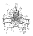
図1及び図2において、制御ブースタ1は、フロントシェル2、センタシェル3及びリアシェル4からなるハウジング5と、ハウジング5内に設けられてハウジング5内のうちフロントシェル2及びセンタシェル3により形成される空間部(符号省略)をフロント定圧室6a及びフロント変圧室7aに画成するフロントダイアフラム8aを備えたフロントパワーピストン9aと、ハウジング5内に設けられてハウジング5内のうちセンタシェル3及びリアシェル4により形成される空間部(符号省略)をリア定圧室6b及びリア変圧室7bに画成するリアダイアフラム8bを備えたリアパワーピストン9bと、フロントパワーピストン9a及びリアパワーピストン9b(以下、適宜、フロントパワーピストン9a及びリアパワーピストン9bをパワーピストン9と総称する。)に形成された孔(符号省略)に気密的に嵌合されパワーピストン9に支持された略筒状のバルブボディ10と、ブレーキペダル(図示省略)に連動する入力ロッド11に連結されバルブボディ10内に配置されたプランジャ12と、バルブボディ10内に配置されてバルブボディ10に対するプランジャ12の相対移動によりフロント変圧室7a及びリア変圧室7bへの作動流体の供給を制御する弁機構13と、バルブボディ10内に配置されアーマチュア14(可動子)により弁機構13をブレーキペダル(図示省略)に連動する入力ロッド11の変位に基づく作動とは別に作動させるソレノイド機構15(電磁付勢手段)と、から大略構成されている。
【0008】
フロント定圧室6a及びリア定圧室6bは、バルブボディ10に形成された通路T1を通して連通している。以下、フロント定圧室6a及びリア定圧室6bを適宜、定圧室6と総称する。
また、フロント変圧室7a及びリア変圧室7bは、バルブボディ10に形成された通路T2を通して連通している。以下、フロント変圧室7a及びリア変圧室7bを適宜、変圧室7と総称する。
本装置はリアシェル4に植設されたスタッドボルト16を介して図示しない車体に取り付けられる。また、本装置には、フロントシェル2に植設されたスタッドボルト17を介して図示しないマスタシリンダが取り付けられる。
【0009】
バルブボディ10は、パワーピストン9に気密的に嵌合されるバルブボディ大径筒部18と、このバルブボディ大径筒部18に連接されリアシェル4に気密的かつ摺動可能に挿通してリアシェル4の後方に延ばされた延長筒部19とからなっている。バルブボディ10は、バルブボディ10とフロントシェル2との間に介装されたバネ(バルブボディ戻しバネ)20により、図1右方向に付勢されている。
【0010】
延長筒部19の開口部19aとリアシェル4の筒状の開口部4aとの間には、有底筒状の可撓性部材からなるブーツ状のカバー21が保持されている。カバー21は、筒状をなし先端部がリアシェル4の筒状の開口部4aに略気密的に保持されたカバー本体22と、カバー本体22に連接されたカバー底部23とからなっている。カバー底部23は、その周縁部が延長筒部19の開口部19aに略気密的に保持され、中央部には入力ロッド11を挿通し、かつ周縁部と中央部との間の部分には大気(作動流体)連通用の孔(符号省略)を形成している。
延長筒部19におけるバルブボディ大径筒部18側の部分(以下、延長筒部厚肉部という。)24は、開口側部分(延長筒部開口側部分という)25及びバルブボディ大径筒部18の内部空間に比して内径寸法が小さくなって(即ち、厚肉に形成されて)いる。また、延長筒部厚肉部24におけるバルブボディ大径筒部18側部分(以下、厚肉部大径部という)26の内径は、延長筒部厚肉部24における延長筒部開口側部分25側の部分(以下、厚肉部小径部という)27の内径に比して大きい値に設定されている。
延長筒部開口側部分25内にはサイレンサ機能及び空気浄化機能を有するフィルタ28が収納されており、フィルタ28を介して大気がバルブボディ10の内部に導入されるようになっている。
【0011】
延長筒部厚肉部24には、一端側がバルブボディ大径筒部18内を介して定圧室6に連通し、他端側が延長筒部開口側部分25に開口する軸方向に延びる通路T3及び一端側が変圧室7に開口し、他端側が厚肉部分の内側に開口する径方向に延びる通路T4が形成されている。通路T4にはプランジャ12に係合してプランジャ12ひいては入力ロッド11に連動する後述するストップキー29が挿入されている。通路T4はストップキー29の挿入孔を兼ねている。
定圧室6は、接続管30を介して図示しないエンジンの吸気装置等の負圧源に接続されており、常時負圧になっている。
【0012】
延長筒部19内の前記通路T3の開口部分の近傍には、弾性変形可能な弁体31の基端部が押え部材32により固定されている。弁体31の先端部と入力ロッド11との間には弁付勢バネ33が介装されており、弁体31の先端部を、後述するコントロールピストン34(真空弁35の弁座)及びプランジャ12のフランジ36(プランジャフランジ36、大気弁37の弁座)に当接するように図1左方向に付勢しており、コントロールピストン34(真空弁35の弁座)に当接することにより通路T3を閉じ(真空弁35を閉弁し)、プランジャフランジ36(大気弁37の弁座)に当接することにより、通路T4を通しての大気と変圧室7との連通を遮断する(大気弁37を閉弁する)ようにしている。この弁体31及びコントロールピストン34(弁座)により前記真空弁35が構成され、この弁体31及びプランジャフランジ36により大気弁37が構成されている。本実施の形態では真空弁35及び大気弁37から前記弁機構13を構成している。
【0013】
また、押え部材32と入力ロッド11との間には入力ロッド戻しバネ38が介装されていて入力ロッド11を後方(図1右方向)に付勢するようにしている。
前記入力ロッド11はブレーキペダル(図示省略)に連動するものになっており、かつ先端側が延長筒部19内に挿入されている。
この入力ロッド11の先端部には、該入力ロッド11に連動する軸状の前記プランジャ12が連結されている。
【0014】
前記ソレノイド機構15は、フロントシェル2に設けたコネクタ部39に気密的に接合されるプラグ40用の引き出し線41を接続したソレノイド42と、ソレノイド42を保持する磁性材料からなるソレノイド保持具43と、前記ソレノイド42への通電によりソレノイド42の電磁力により作動されて図1右方向に変位する略筒状の前記アーマチュア14(可動子)と、から大略構成されている。アーマチュア14は所定の外径、内径寸法のアーマチュア本体44と、アーマチュア本体44に比して外径寸法が小さく内径寸法が同等でアーマチュア本体44に連接したアーマチュア小径部45とからなっている。アーマチュア小径部45の端部には略筒状のコントロールピストン34に形成した軸部34aが当接し得るようになっている。
【0015】
ソレノイド保持具43は、前記ソレノイド42を開口側に収納する二重筒状部46と、二重筒状部46の閉塞側部分から延設された筒状の延長部(保持具延長部)47と、からなっている。保持具延長部47は基端側から先端側に向けて、内径が、大、小、中と段階的に変化する第1、第2、第3延長部47a,47b,47cとからなっている。第1、第2延長部47a,47bの外径寸法は第3延長部47cになるに従って逓減するものになっている。第1延長部47aの内径寸法は、アーマチュア小径部45の外径寸法に比して僅かに大きくされている。また、第3延長部47cの外径寸法は厚肉部大径部26の内径に比して僅かに小さい値にされている。
ソレノイド保持具43は、二重筒状部46をバルブボディ大径筒部18内に配置し、第3延長部47cを厚肉部大径部26に挿入させてバルブボディ10内に配置されている。
【0016】
また、ソレノイド保持具43の二重筒状部46の開口部には、略筒状の出力ロッド嵌合部材48が結合されており、先端側が前記図示しないマスタシリンダのピストンに接続される出力ロッド49の基端部(符号省略)を嵌合し、前記バルブボディ戻しバネ20のバネ受けを兼ねる押え板50と共に出力ロッド49を開口部内で軸方向に移動可能に保持するようにしている。
出力ロッド嵌合部材48は、出力ロッド49の基端部及びゴム等の弾性体からなるリアクションディスク51が収納される出力ロッド嵌合部材本体52と、出力ロッド嵌合部材本体52に連接しこの出力ロッド嵌合部材本体52に比して内径が小さく、かつ、二重筒状部46の内径と同等の内径の出力ロッド嵌合部材延長部53と、出力ロッド嵌合部材本体52に径方向外方に突出形成され、前記二重筒状部46の外方の筒部(符号省略)に嵌合するフランジ(出力ロッド嵌合部材フランジ)54と、からなっている。
【0017】
出力ロッド嵌合部材48及びアーマチュア14とプランジャ12の間になるように略筒状の中間部材55がプランジャ12に嵌合されている。
中間部材55は、アーマチュア本体44に形成された環状凹部(符号省略)に収納される有底筒部(中間部材有底筒部)56と、中間部材有底筒部56の底部に連接してプランジャ12に嵌装する中間部材延長部57と、中間部材有底筒部56の開口縁部に外方に突出形成され出力ロッド49の基端部との間に配置されるリアクションディスク51に当接可能に出力ロッド嵌合部材本体52に収納されるフランジ(中間部材フランジ)58と、から大略構成されている。中間部材有底筒部56には、リアクションディスク51とプランジャ12との間に配置される円板部材59を収納するようにしている。
【0018】
前記コントロールピストン34は、外径寸法が第3延長部47cの内径に比して僅かに小さい有底筒状のコントロールピストン本体60と、コントロールピストン本体60の底部(符号省略)に延設され第2延長部47bに形成された貫通孔(符号省略)を挿通してアーマチュア14に当接可能に延びる前記軸部34aと、コントロールピストン本体60の先端側に形成され前記厚肉部小径部27にシール部材61を介して摺動可能に挿入されるコントロールピストン摺動部62と、コントロールピストン摺動部62に段差82をもって延設され真空弁35の弁座をなすコントロールピストン弁座部63と、から大略構成されている。
【0019】
前記プランジャ12は、前記中間部材55の中間部材延長部57を挿通する軸部(プランジャ軸部)64と、プランジャ軸部64に連接されこのプランジャ軸部64に比して大径で、入力ロッド11の先端部が嵌合される穴(符号省略)が形成されたプランジャ基端部65と、プランジャ基端部65の端部側に径方向外方に突出形成された前記プランジャフランジ36(大気弁37の弁座を構成する。)とからなっている。プランジャ基端部65の外周部に環状の溝(符号省略)が形成されており、この溝に前記通路T4に挿通されたストップキー29が嵌合されてハウジング5内におけるバルブボディ10の後退変位、及びバルブボディ10に対するプランジャ12の軸方向の相対的な後退変位を規制するようにし、図1に示す初期状態〔入力ロッド11が押圧されておらず(ブレーキペダル非操作)、ソレノイド42が通電されておらず(自動ブレーキ非作動)、かつ定圧室6と変圧室7とが一定圧(負圧)の状態〕を設定している。
プランジャ基端部65とコントロールピストン34との間には戻しバネ(コントロールピストン戻しバネ)66が介装されており、軸方向に関してプランジャ基端部65とコントロールピストン34(ひいてはアーマチュア14)とを離間する方向に付勢している。
【0020】
バルブボディ10における通路T4の近傍部分でリア定圧室6bに臨む部分には凹部(符号省略)が形成されている。この凹部には、入力ロッド11のバルブボディ10に対する相対移動を検出するスイッチ67が収納され、かつソレノイド保持具43に設けた2本のピン68(図3に示す。)を貫通させることによりソレノイド保持具43(ひいてはバルブボディ10)に固定されている。
スイッチ67は、図3に示すように、接点稼働子69と、接点稼働子69を外面側に露出して配置すると共に複数のリード線70を収納するスイッチ本体71とを有しており、接点稼働子69をリア定圧室6bに臨ませて(図3左側に向けて)配置している。
【0021】
スイッチ67の近傍には、接点稼働子69に対する当接部72を備えたスイッチ操作ロッド73が配置されている。スイッチ操作ロッド73は、当接部72を備えた板状の操作ロッド部74と、操作ロッド部74に直立して設けられた軸状の操作ロッド本体75と、からなっている。操作ロッド本体75は、バルブボディ10に形成された貫通孔76を挿通され、その先端部がストップキー29に臨むように配置されている。バルブボディ10の貫通孔76の通路T4側の開口部には、シール部材77が設けられており、操作ロッド本体75のバルブボディ10に対する摺動を気密的に行えるようにしている。バルブボディ10にはシール部材77を押えるようにしてガイド78が設けられており、シール部材77の位置決めを行うようにしている。操作ロッド本体75の先端部には止め輪79が固定されている。止め輪79とガイド78との間には、スイッチ用バネ80が介装されており、当接部72を接点稼働子69に押圧する方向(操作ロッド本体75の先端部がストップキー29に当接する方向)に付勢するようにしている。ガイド78は図示しないシール部材の位置決め及びバネ80の案内を行う。
【0022】
操作ロッド本体75の長さは、通路の幅〔バルブボディ10のストップキー29に臨む面のうち後側(図1右側)当接面81aと前側(図1左側)当接面81bの間の長さ〕、入力ロッド11操作による差圧発生時の入力ロッド11(プランジャ12、ストップキー29)とバルブボディ10の相対変位、ソレノイド機構15操作(自動ブレーキ)時に生じるコントロールピストン34の前記段差82(コントロールピストン摺動部62及びコントロールピストン弁座部63により形成される段差)と厚肉部小径部27との間の隙間S(図示省略)等に基づいて設定される。
そして、後述するように、図1に示す状態でソレノイド機構15が操作され、コントロールピストン34が弁体31を図1右方に押圧して大気弁37が開弁し(この状態で段差82と厚肉部小径部27との間に隙間S(図示省略)が生じている。)、定圧室6と変圧室7との間に差圧が生じ、隙間Sを維持した状態でバルブボディ10が前記差圧により図1左方向に前進する。この際、図4に示すようにストップキー29はストップキー29の右面が後側当接面81aに当接しており(スイッチ67の反力とスイッチ用バネ80のバネ力とが釣り合った状態)、この状態で、ブレーキペダルが踏まれて入力ロッド11が前進すると、ストップキー29も連動して図1左方向へ移動して、図3に示す位置関係になり、スイッチ67が反転する(接点稼働子69が当接部72に押された状態から押されない状態になる)。一方、上述したようにスイッチ67が反転することにより、自動ブレーキ中にブレーキペダルが操作されたことを検出できる。
【0023】
また、ブレーキペダル非操作かつ自動ブレーキ非作動では、制御ブースタ1は図1に示すように、大気弁37及び真空弁35は共に閉じた状態にあり、かつ、ストップキー29は、バルブボディ10の通路T4内において、バルブボディ10の軸方向に関し、中間位置状態にある。図1中、83はリヤシェル10に形成されたストップキー戻り規制部であり、前記中間位置状態において、ストップキー29は図1に示すようにストップキー戻り規制部83に当接している。
【0024】
上述したように構成した制御ブースタ1では、自動ブレーキ非作動時にブレーキペダルが操作されると、次のように作用する。
すなわち、
(1)ブレーキペダルが踏み込まれ入力ロッド11が押されると、プランジャ12が図1に示す状態から前進(図1左方向)する。このように入力ロッド11及びプランジャ12が前進することに伴い、ストップキー29もストップキー戻り規制部83から離れて通路T4内を、中間位置状態(図1)から図3に示す前側当接面81b側に前進する。
そして、プランジャ12(ひいてはプランジャフランジ36)が図1に示す状態からバルブボディ10に対して相対的に前進することにより大気弁37が開弁し、変圧室7内の圧力が上昇し、変圧室7と定圧室6との間に差圧が生じ、この差圧に基づきバルブボディ10がハウジング5に対して前進する。バルブボディ10の作動に伴い、リアクションディスク51を介して出力ロッド49には、前記差圧に基づく推力が発生しており、このときの出力ロッド49からの反力に基づきリアクションディスク51は変形して円板部材59を介してプランジャ12に当接するようになり、入力ロッド11へ出力反力が伝達される。
【0025】
ここで、ブレーキペダルの踏込操作に基づき入力ロッド11に作用する力の大きさ(ブレーキペダルの踏込力の大きさ)と、出力ロッド49からリアクションディスク51及びプランジャ12を介して入力ロッド11に伝達される反力の大きさとが均衡した場合は、大気弁37も真空弁35も閉じられた閉弁状態となり、制御ブースタ1の出力は一定になる。したがって、この状況においては、ストップキー29は、通路T4内を、前記中間位置状態から前側当接面81b側へ前進した状態になった後、再び前記中間位置状態(図1)に戻っている。
【0026】
(2)次に、この状態(中間位置状態)から、ブレーキペダルの踏込操作力を弱めたり、あるいは踏込操作を解除したりして入力ロッド11に作用する力の大きさ(ブレーキペダルの踏込力の大きさ)を減じた場合、入力ロッド11は、入力ロッド戻しバネ38と弁付勢バネ33とリアクションディスク51からの反力(円板部材59の戻り方向端まで作用する)の作用によって、バルブボディ10に対して相対的に後退する。
これにより、真空弁35が開弁して変圧室7内の圧力は減少し、バルブボディ10自体もハウジング5に対して相対的に後退する。
そして、上述した入力ロッド11がバルブボディ10に対して後退し、かつバルブボディ10自体がハウジング5に対して後退することにより、ストップキー29は、通路T4内を、中間位置状態から後側当接面81a側へ後退した状態(図4)になる。
ここで、ブレーキペダルの踏込操作の減少または解除に基づき入力ロッド11に作用する力の大きさ(ブレーキペダルの踏込力の大きさ)と出力ロッド49からリアクションディスク51、プランジャ12を介して入力ロッド11に伝達される反力の大きさとが均衡した場合は、大気弁37も真空弁35も再び閉じられた閉弁状態となり、制御ブースタ1の出力は一定になる。したがって、この状況においては、ストップキー29は、通路T4内を中間位置状態から後側当接面81a側へ後退した状態(図4)から前進し、再び中間位置状態(図1)に戻る。そして、変圧室7が定圧室6と同圧になった場合は、ストップキー29はリヤシェル4に設けられたストップキー戻り規制部83に当接した状態(図1)になる。
【0027】
(3)また、ブレーキペダル非操作で自動ブレーキ(ソレノイド42に通電する自動ブレーキ)時には、ソレノイド42への通電によりアーマチュア14には図1右方の力が作用し、コントロールピストン34がアーマチュア14の図1右方の力を受け、コントロールピストン戻しバネ66の付勢力、弁付勢バネ33の付勢力及び弁体31に作用する差圧力に抗して、段差82と厚肉部小径部27との間に隙間Sを形成しつつ、図1右方に移動し(バルブボディ10に対して相対的に後退し)、弁体31をプランジャ12の大気弁37の弁座(プランジャフランジ36)より引き離し、大気弁37のみが開弁する。この大気弁37のみの開弁により、変圧室7には大気が導入され、変圧室7内の圧力が上昇し、定圧室6と変圧室7との間に差圧が生じ、この差圧に基づきバルブボディ10自体がハウジング5に対して前進する。
このとき、入力ロッド11及びプランジャ12は、パワーピストン9(バルブボディ10)に係合されておらず、またブレーキペダルも踏み込まれていないので、変位することがなく、ストップキー29は、バルブボディ10が前進することに伴い、通路T4内を、中間位置状態(図1)から後側当接面81a側へ後退した状態(図4)になる。この際、当接部72がスイッチ67の接点稼働子69を押圧し、スイッチ67の反力とスイッチ用バネ80のバネ力とが釣り合った状態になっている。
【0028】
この後、ソレノイド42の電磁力が調整されることにより、コントロールピストン34がコントロールピストン戻しバネ66の付勢力にのみ抗して、弁体31に当接し得るだけの大きさにされると、弁付勢バネ33の付勢力及び弁体31に作用する差圧力によって、コントロールピストン34は弁体31をプランジャ12の大気弁37の弁座(プランジャフランジ36)より引き離している状態から、真空弁35が閉じた状態(この状態で段差82と厚肉部小径部27との間に隙間Sが形成されている)で、弁体31が再びプランジャ12の大気弁37の弁座(プランジャフランジ36)に当接する状態に戻され、大気弁37が閉弁する。このように真空弁35及び大気弁37が閉弁した際、当接部72がスイッチ67の接点稼働子69を押圧し、スイッチ67の反力とスイッチ用バネ80のバネ力とが釣り合った状態になっている。
なお、この状態においても、バルブボディ10は、入力ロッド11及びプランジャ12に対して相対的に前進した位置にある。
ストップキー29は、バルブボディ10が前進したままであることにより、通路T4内を、中間位置状態(図1)から、後側当接面81a側に移動したままの状態にある(図4)。
【0029】
(4)さらに、ソレノイド42の電磁力が調整されることにより、コントロールピストン34がコントロールピストン戻しバネ66の付勢力にのみ抗して、弁体31に当接し得るだけのソレノイド42の電磁力を有しないようになると、コントロールピストン34がそのコントロールピストン戻しバネ66の付勢力によって弁体31から引き離され、真空弁35が開弁する。真空弁35が開弁することにより、変圧室7の圧力が減圧され、変圧室7と定圧室6との差圧が減少し、バルブボディ10はハウジング5に対して後退する。初期位置に戻ると、ストップキー29は、通路T4内を後側当接面81a側へ移動した位置から図1に示す中間位置状態へ移動する。
【0030】
(5)また、自動ブレーキ作動で上述したようにソレノイド42の電磁力が調整され真空弁35及び大気弁37が閉じた状態で、ブレーキペダルを踏み込んだ場合、入力ロッド11及びプランジャ12がバルブボディ10に対して前進するので、ストップキー29は通路T4内を、後側当接面81a側へ移動している状態(図示省略)から中間位置状態(図1)へ移動する。
したがって、自動ブレーキ作動によって発生しているブレーキ力によるプランジャ12への反力よりも、ブレーキペダルの踏み込みによる入力ロッド11への入力が大きいときには、ストップキー29は、後側当接面81a側へ移動した位置から図1に示す中間位置状態側へ移動する。
また、上述したように、ストップキー29が後側当接面81a側へ移動している状態(図示省略、スイッチ操作ロッド73に作用するスイッチ67からの反力と前記バネのバネ力が釣り合った状態)から中間位置状態(図1)へ移動する際において、後側当接面81a側へ移動している状態(図4参照)では、上述したようにスイッチ67にはスイッチ用バネ80の戻し力しかかからないようになっている一方、中間位置状態(図1)へ移動する際には、当接部72が接点稼働子69から離間する(スイッチ操作ロッド73がスイッチ67に対して相対的に離間方向に移動する)ことによりスイッチ67には負荷がかからない。このため、自動ブレーキ中のブレーキペダル操作により惹起するスイッチ67への過大な負荷及びこの過大な負荷に伴うスイッチ67の破損を防止することができると共に、上述したように自動ブレーキ中のブレーキペダル操作をスイッチ67が開することにより検出することができる。
【0031】
(6)ブレーキアシスト(BA)作動中に、ブレーキペダルの操作を解除した状況においては、次のように作用する。
このブレーキアシスト(BA)の作動は、図1に示す初期状態におけるストップキー29の位置が、ソレノイド42の電磁力によって通路T4内を後側当接面81a側に移動している場合と同様に作用する。
したがって、ブレーキアシスト作動中に、ブレーキペダルの踏み込みを解除すれば、ストップキー29は、通路T4内を、後側当接面81a側に移動する。このため、ブレーキアシスト中のブレーキペダルの操作解除は、ストップキー29が図1の状態から図4の状態に変化することで検出できる。
上述したように、自動ブレーキ中のブレーキペダルの操作はストップキー29が図4の状態から図1の状態に変化することで検出できる。
また、本実施例によれば、ブレーキペダルに操作に基づくブレーキアシスト中のブレーキペダルの操作解除は、ストップキー29が図1の状態から図4の状態に変化することで検出できる。
【0032】
次に、本発明の第2実施の形態を図5及び図6に基づいて説明する。
この実施の形態は、操作ロッド本体75の基端部側(操作ロッド部74)に、バルブボディ10の貫通孔76に比して大径の所定長さの大径部84(スイッチ操作ロッド移動規制機構)を備えている。
この実施の形態では、スイッチ用バネ80の付勢力またはバルブボディ10の前進に伴うスイッチ操作ロッド73のバルブボディ10に対する相対的な後退により、当接部72が接点稼働子69に当接した場合に、大径部84がバルブボディ10に当接し、それ以上のスイッチ操作ロッド73の相対変位が抑制され、スイッチ67にかかる負荷が低減されその破損が防止されることになる。また、本実施の形態の大径部8は簡易に構成されるので、装置全体の複雑化を招くことなくスイッチ67にかかる負荷の低減及びその破損の防止を図ることができる。
【0033】
次に、本発明の第3実施の形態の制御ブースタを図7ないし図10に基づいて説明する。
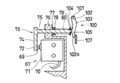
図7及び図8において、ストップキー29Aには揺動レバー100 が支軸101 を介して揺動可能に支持されている。支軸101 はストップキー29Aにおけるプランジャ12に近い側に設けられている。揺動レバー100 は支軸101 に対しプランジャ12から離間する方向(図7下方向)に延びている。以下、便宜上、揺動レバー100 の支軸101 から図7下方向に延びた部分を揺動レバー本体102 という。揺動レバー本体102 の支軸101 近傍には、バルブボデー10の後側当接面81aに突出する湾曲部(第1湾曲部)103 が形成されている。
【0034】
揺動レバー本体102 の先端部102aと第1湾曲部103 との間の部分には前側当接面81b側に突出する湾曲部(第2湾曲部)104 が形成されている。
プランジャ12とバルブボディ10との位置関係が所定の状態で第2湾曲部104 がスイッチ操作ロッド73の止め輪79側の端部105 に当接する(図8、図9)ようになっている。
【0035】
ハウジング5における通路T4の近傍には支持部材106 が保持されており、支持部材106 の先端部107 が通路T4に挿入されている。図7及び図8に示すブレーキペダル非操作状態で、支持部材106 の先端部107 には、揺動レバー100 の所定の回動により、ストップキー29A及び揺動レバー本体102 の先端部102aが当接するようになっている。
ブレーキ解除位置でブレーキぺダルが操作されていない場合(図7、図8。ブレーキペダル非操作状態)は、揺動レバー100 はストップキー29Aとともに支持部材106 の先端部107 に当接されている。そして、図7及び図8に示すように、ストップキー29Aはこれ以上のバルブボディ10に対する相対的な右方への移動(後側当接面81a側への移動)が規制され、揺動レバー100 も支軸101 を中心とする図7反時計回りの回動が規制されている。
このブレーキペダル非操作状態では、図7及び図8に示すように、揺動レバー本体102 の第2湾曲部104 がスイッチ操作ロッド73の端部105 に当接してスイッチ操作ロッド73を押圧して、スイッチ67の接点稼働子69から離間(スイッチ67をオフ)させている。
【0036】
上述したように構成した第3実施の形態の作用を、以下に、項目分けして説明する。
(1)「通常ブレーキ操作」
解除位置でブレーキペダルが操作されていない場合(図7に示す状態、ブレーキペダル非操作状態)に、ブレーキペダルを操作した場合は、プランジャ12がバルブボディ10に対して図7左方に移動し、このプランジャ12の移動に伴いストップキー29Aひいては揺動レバー100 の支軸101 がバルブボディ10に対して、図7左方へ相対移動することになる。また、ブレーキペダルの操作に基づくバルブボディの図7左方への移動によって支持部材106の先端部107が図7右方へ相対的に移動し揺動レバー100 の第2湾曲部104 は支軸101 に対し右方へ相対移動できるようになる。これに伴いスイッチ操作ロッド73は第2湾曲部104 に当接して揺動レバー100 を図7反時計方向に回動させつつスイッチ用バネ80のバネ力により右方に移動し、スイッチ67に当接する(スイッチ67はオンとなる)。
この段階では、揺動レバー100 の第2湾曲部104 はスイッチ操作ロッド73から離れていない状態である。
【0037】
そして、ブレーキペダルの操作力と出力反力とがバランスしたときには、バルブボディ10に対するプランジャ12の相対位置は図7の位置関係に戻るが、揺動レバー100 は図7に示すブレーキペダル非操作状態と異なり、支持部材106 の先端部107 から離間していて回動規制が解除されている。
これにより、スイッチ67はオン状態に保たれている。
【0038】
その後、ブレーキペダルの操作が解除された場合(この段階では、上述したようにバルブボディ10及びプランジャ12に関しては図7に示す位置関係にある)は、プランジャ12がバルブボディ10に対して図7右方に移動する。これに伴い、揺動レバー100 の支軸101 (ストップキー29A)が、図7に示す状態から、バルブボディ10に対して図7右方へ相対移動することになる。
【0039】
これにより、揺動レバー100 は、第1湾曲部103 がバルブボディ10の後側当接面81aに当接する。そして、第1湾曲部103 が後側当接面81aに当接した状態で揺動レバー100 の支軸101 が図7右方に移動することにより、揺動レバー本体102 は第1湾曲部103 を中心として図7時計方向に回動し、第2湾曲部104 が図7左方へ相対移動(回転)する。
このため、揺動レバー100 は、スイッチ操作ロッド73をスイッチ用バネ80のバネ力に抗して図7左方に移動させることとなり、スイッチ操作ロッド73をスイッチ67の接点稼働子69から離間(すなわち、スイッチ67をオフ状態)させるようになる。
【0040】
なお、ブレーキペダルの操作解除が途中で中止され、ブレーキペダルの操作力と出力反力とがバランスした状態と同じになり、ブレーキペダルの操作解除が終了したときは、図7に示すバルブボディ10とプランジャ12との位置関係に戻る。
ブレーキペダルの操作解除が終了した状態は、バルブボディ10とプランジャ12との位置関係だけみれば、前述のブレーキペダルを操作し、ブレーキペダルの操作力と出力反力とをバランスさせた場合の位置関係と同じであるが、ストップキー29A及び揺動レバー100 は、揺動レバー本体102 の先端部102aが支持部材106の先端部107に当接することによって移動及び回動規制されることにより、スイッチ67がオフ状態になる点が異なる。
【0041】
(2)「自動ブレーキ操作」
解除位置でブレーキペダルが操作されていない場合に、自動ブレーキが作動した(自動ブレーキモードとされた)場合は、バルブボディ10及びプランジャ12に関して図7に示す位置関係が維持された状態で、コントロールピストン4が図7右方に移動することによって、作動弁(大気弁37)から変圧室7に作動気体が供給される点が、前記「通常ブレーキ操作」の場合に変圧室7への作動気体供給時における作動(プランジャ12がバルブボディ10に対して図7左方向に相対的に移動する)と根本的に異なっている。
【0042】
上述した自動ブレーキの作動によってコントロールピストン4が図7右方に移動して大気弁37が開いて、変圧室に大気が導入され、変圧室7及び定圧室6との差圧によりパワーピストン9ひいてはバルブボディ10が前進(図7左方向への移動)する。
このバルブボディ10の前進によって、揺動レバー100 の支軸101 (ストップキー29A)が、図7の状態から、バルブボディ10に対して右方へ相対移動することになる。これにより、揺動レバー100 の第1湾曲部103 には、バルブボディ10の後側当接面81aが当接し(図9参照)、揺動レバー本体102 は第1湾曲部103 を中心として図9時計方向に回動し、第2湾曲部104 がさらに左方へ相対移動(回転)してスイッチ操作ロッド73を押圧する。そして、揺動レバー本体102 が上述したように時計方向に回動することによりスイッチ操作ロッド73がスイッチ用バネ80のバネ力に抗して図9左方に移動され、スイッチ67の接点稼働子69から離間する(スイッチ67がオフする)ことになる(すなわち、自動ブレーキモードにおけるブレーキペダル非操作状態でスイッチ操作ロッド73は揺動レバー100 に押されてスイッチ67の接点稼働子69から離間した状態にされる)。
【0043】
また、自動ブレーキ作動で上述したようにソレノイド42の電磁力が調整され真空弁35及び大気弁37が閉じた状態(自動ブレーキモードにおけるブレーキペダル非操作状態)で、ブレーキペダルを踏み込んだ(入力ロッドがブースタ出力が増加する方向へ作動された)場合、入力ロッド11及びプランジャ12(ストップキー29A)がバルブボディ10に対して前進し、揺動レバー100 は図10に示す状態になる。
【0044】
すなわち、揺動レバー100 は、その支軸101 が図9左方に移動するのに伴い、スイッチ操作ロッド73を介してスイッチ用バネ80のバネ力に押されつつその自重バランスにより図9反時計方向に回動する。そして、スイッチ操作ロッド73が図9右方向に所定量、移動すると、スイッチ操作ロッド73はスイッチ67の接点稼働子69に当接してスイッチ67がオンする(スイッチ操作ロッドは揺動レバー100 を介したバルブボディ10からの押圧が解除されてスイッチ67に当接する)。この後、揺動レバー100 は、図9反時計方向にさらに回動し、図10に示すように第1湾曲部103 が後側当接面81aが当接した状態になる。
【0045】
上述したように自動ブレーキモードにおけるブレーキペダル非操作状態では図9に示すようにスイッチ操作ロッド73がスイッチ67から離間されていてスイッチ67はオフされる一方、当該自動ブレーキモードにおけるブレーキペダル非操作状態でブレーキペダルが操作されると、スイッチ67はオンされる(図10参照)ので、自動ブレーキ中のブレーキペダル操作を確実に検出することができる。
【0046】
また、上述したスイッチ67の作動に際し、自動ブレーキモードにおけるブレーキペダル非操作状態ではスイッチ操作ロッド73がスイッチ67の接点稼働子69から離間されていることによりスイッチ67には、過大な荷重がかかることがない。また、自動ブレーキモードにおいてブレーキペダルが操作された場合には、図10に示すようにスイッチ操作ロッド73がスイッチ67の接点稼働子69に当接するものの、この当接はスイッチ用バネ80のバネ力によってのみ行われるので、スイッチ67には不要に大きな荷重がかかることがない。
【0047】
本第3実施の形態では、揺動レバー100 をストップキー29Aに揺動可能に支持しているが、揺動レバー100 をプランジャ12に揺動可能に支持するように構成してもよい。なお、本第3実施の形態のようにストップキー29Aに揺動レバー100 を設けるようにする方が、作製しやすく望ましい。
【0048】
前記各実施の形態では、スイッチ67をリア定圧室6b(定圧室6)に設けているので、スイッチ67にかかる圧力は略一定であり、スイッチ67にかかる圧力が大きく変化するようなことを防止できる。
すなわち、上述した特表平10−505041号公報に示す制御ブースタではスイッチを変圧室に配置しており、例えばブレーキペダルによるブレーキ操作毎にスイッチが大気圧に曝され、スイッチにかかる圧力が頻繁に変化してしまうことになるが、前記各実施の形態によれば、上記公報の制御ブースタが惹起する上記問題を回避することができる。
【0049】
また、制御ブースタは、車室内における取付けの関係から、一般に、リアシェル(上記実施の形態ではリアシェル4)に設けられたボルト(上記各実施の形態ではスタッドボルト16)で車室内壁に固定される。このため、組付作業上、フロントシェル(上記実施の形態ではフロントシェル2)側から信号線(上記各実施の形態では引き出し線41及びリード線70)が外部に引き出されるようにしている。そして、上記各実施の形態では、スイッチ67のリード線70を定圧室6に案内しており、リード線70を装置外部と接続する上で、変圧室7と定圧室6とを区画するリアパワーピストン9bを挿通する必要がなく、当該リアパワーピストン9bにリード線70を挿通するために必要とされる大きなシール性の確保が不要となる。
【0050】
すなわち、上述した特表平10−505041号公報に示す制御ブースタではスイッチを変圧室に配置しており、上述したように組付作業を考慮した場合には、そのスイッチの信号線を、変圧室と定圧室とを区画するパワーピストンを挿通させて外部に引き出すことになる。この場合には、スイッチの信号線の挿通部分を通して変圧室及び定圧室が不用意に導通することがないように当該挿通部分を十分に大きなシール性をもってシールする必要があり、シール性の確保が大掛かりになり、生産性が低下する虞があるが、上記各実施の形態では、上述したように大きなシール性の確保が不要になることから、上記特表平10−505041号公報に示す制御ブースタが惹起する生産性の低下を招くことがない。
【0051】
【発明の効果】
請求項1記載の発明によれば、入力ロッドが作動された際にはスイッチ操作ロッドは、前記入力ロッドがバルブボディに対して近づく方向に相対移動するときに前記入力ロッドの力を受けてスイッチに対して相対的に移動して前記スイッチが反転するので、自動ブレーキ作動中のブレーキペダル(ひいては入力ロッド)操作時にスイッチに入力ロッド操作に伴う荷重がかかるようなことがなく、従来技術で惹起する虞があったスイッチの破損を招くことがない。
請求項2記載の発明によれば、スイッチ操作ロッド移動規制機構がスイッチの接点稼働子に対するスイッチ操作ロッドの押圧を抑えるので、スイッチにかかる負荷が低減されスイッチの破損が防止される。
請求項3記載の発明によれば、スイッチ操作ロッド移動規制機構として大径部が簡易に構成できることから、スイッチにかかる負荷の低減及びその破損の防止を装置全体の複雑化を招くことなく果たすことができる。
【0052】
請求項4記載の発明によれば、自動ブレーキモードにおけるブレーキペダル非操作状態ではスイッチ操作ロッドがスイッチから離間されていてスイッチはオフされる一方、当該自動ブレーキモードにおけるブレーキペダル非操作状態でブレーキペダルが操作されると、スイッチ操作ロッドがスイッチに当接してスイッチはオンされるので、自動ブレーキ中のブレーキペダル操作を確実に検出することができる。
また、スイッチのオフ、オン作動に際し、自動ブレーキモードにおけるブレーキペダル非操作状態ではスイッチ操作ロッドがスイッチから離間されていることによりスイッチには、過大な荷重がかかることがなく、自動ブレーキモードにおいてブレーキペダルが操作された場合には、スイッチ操作ロッドがスイッチに当接するものの、この当接はスイッチ用バネのバネ力によってのみ行われるので、スイッチには不要に大きな荷重がかかることがなく、従来技術で惹起する虞があったスイッチの破損を招くことがない。
【0053】
請求項5記載の発明によれば、揺動レバーをストップキーに揺動可能に支持しており、プランジャに設ける場合に比して作製しやすくなる。
請求項6記載の発明によれば、スイッチを定圧室に設けており、スイッチにかかる圧力は略一定であり、スイッチにかかる圧力が大きく変化するようなことを防止できる。
【図面の簡単な説明】
【図1】本発明の第1実施の形態を示す断面図(図2の部分拡大図)である。
【図2】図1の制御ブースタを示す断面図である。
【図3】図1のスイッチの取付状態を示す図である。
【図4】図3のスイッチの接点稼働子に可動接点が押圧している状態を示す図である。
【図5】本発明の第2実施の形態を示す図である。
【図6】図5の制御ブースタの作用を示す図である。
【図7】本発明の第3実施の形態の制御ブースタを示す断面図である。
【図8】図7のスイッチの状態を示すための断面図である。
【図9】図7の制御ブースタの自動ブレーキモードにおけるブレーキペダル非操作状態のスイッチの状態を示す断面図である。
【図10】自動ブレーキモードにおいてブレーキペダルを操作した時のスイッチの状態を示す断面図である。
【符号の説明】
1 制御ブースタ
6 定圧室
7 変圧室
14 アーマチュア
15 ソレノイド機構(電磁付勢手段)
67 スイッチ
69 接点稼働子
72 当接部
73 スイッチ操作ロッド
100 揺動レバー[0001]
BACKGROUND OF THE INVENTION
The present invention relates to a control-type booster having an automatic brake function that electromagnetically operates an atmospheric valve or a vacuum valve.
[0002]
[Prior art]
As an example of a conventional control booster of this type, a power piston that defines a constant pressure chamber and a variable pressure chamber in the housing, and an input rod that is provided in a valve body supported by the power piston and is linked to a brake pedal. A valve mechanism for controlling the supply of working fluid to the variable pressure chamber by movement of the plunger, an electromagnetic biasing means having a mover for operating the valve mechanism separately from the operation of the input rod, and a power source And an electromagnetic solenoid that operates the plunger upon receipt of electric power, and a switch that is attached to the power piston and installed in the constant pressure chamber, and moves in the axial direction in conjunction with the input rod. There is a control booster having a switch rod that activates a switch when it moves a predetermined amount relative to the power piston.
In this control booster, a brake force is generated by using a differential pressure generated between the variable pressure chamber and the constant pressure chamber by the brake pedal operation (hereinafter referred to as pedal operation brake operation) and a brake pedal (input). In addition to the operation of the rod, the electromagnetic urging means is operated to generate a differential pressure between the variable pressure chamber and the constant pressure chamber to generate a braking force (hereinafter referred to as an automatic brake operation for convenience). ing.
[0003]
[Problems to be solved by the invention]
By the way, in the control booster of the prior art described above, since the switch rod is connected or engaged with the plunger, the movement amount of the plunger is transmitted to the switch (fixed contact of the switch) as it is, and the switch is forcibly operated and damaged. There was a risk of doing so.
Further, in the control booster, it is desired to stop the automatic brake operation when the pedal operation brake operation is performed during the automatic brake operation. In order to meet this demand, even if the above-described prior art switch is configured to be used for detection of pedal operation brake operation during automatic braking, the above-described prior art switch does not have a plunger as described above. The actual situation is that the relative movement amount may be transmitted to the switch as it is and may be damaged, and the above-mentioned demand cannot be fulfilled appropriately.
Further, as another example of the prior art, there is a control booster shown in JP-T-10-505041. In this control booster, the switch is disposed in the variable pressure chamber. For example, the switch is exposed to atmospheric pressure every time the brake operation is performed by the brake pedal, and the pressure applied to the switch frequently changes.
[0004]
The present invention has been made in view of the above circumstances, and an object of the present invention is to provide a control booster capable of appropriately detecting pedal operation brake operation during automatic braking.
Another object of the present invention is to reduce the pressure change acting on the switch.
[0005]
[Means for Solving the Problems]
According to the first aspect of the present invention, a power piston that defines a constant pressure chamber and a variable pressure chamber in a housing, and a plunger that is connected to an input rod that is provided in a valve body supported by the power piston and interlocks with a brake pedal. A valve mechanism for controlling the supply of the working fluid to the variable pressure chamber by the movement of, and an electromagnetic biasing means having a mover for operating the valve mechanism separately from the operation of the input rod. A control booster that outputs a thrust generated in the power piston by a differential pressure generated between the variable pressure chamber and the constant pressure chamber based on operation;
A switch for detecting relative movement of the input rod with respect to the valve body, a switch operating rod for operating the switch, and a switch spring for biasing the switch operating rod toward the contact operating element pushing direction of the switch. Prepared,The switch operating rod receives the force of the input rod when the input rod moves relative to the valve body and moves relative to the valve body away from the valve body. Sometimes attached to the valve body so as not to receive the force of the input rod,
TheIn the direction of increasing the star outputThe input rod isWhen actuated, the switch operating rod moves relative to the switch and the switch is inverted.
According to a second aspect of the present invention, in the configuration of the first aspect, the switch operating rod movement restricting mechanism is provided so as to suppress the pressing of the switch operating rod against the contact operating element of the switch by the switch spring. To do.
According to a third aspect of the present invention, in the configuration of the second aspect, the switch operating rod is provided through the valve body, and the switch operating rod movement restricting mechanism is formed on the switch operating rod. The large-diameter portion has a large diameter compared to the through-hole.
[0006]
According to a fourth aspect of the present invention, there is provided a power piston that defines a housing with a constant pressure chamber and a variable pressure chamber, and a plunger that is provided in a valve body supported by the power piston and is connected to an input rod that is linked to a brake pedal. A valve mechanism for controlling the supply of the working fluid to the variable pressure chamber by the movement of, and an electromagnetic biasing means having a mover for operating the valve mechanism separately from the operation of the input rod. A control booster for outputting a thrust generated in the power piston by a differential pressure generated between the variable pressure chamber and the constant pressure chamber based on operation, the switch detecting a relative movement of the input rod with respect to the valve body; A switch operating rod for operating the switch, and a switch bar for biasing the switch operating rod toward the contact operating element pushing direction of the switch. And the switch operating rod is pushed by the valve body via a swing lever that is swingably supported by the plunger and separated from the switch in a brake pedal non-operating state in the automatic brake mode. When the input rod is actuated in the direction in which the booster output increases in the brake pedal non-operating state in the automatic brake mode, the pressure from the valve body via the swing lever is released and the It contacts the switch.
According to a fifth aspect of the present invention, in the configuration according to the fourth aspect, the swing lever is swingably supported by a stop key integrated with the plunger.
According to a sixth aspect of the present invention, in the configuration according to any one of the first to fifth aspects, the switch is provided in a constant pressure chamber.
[0007]
Embodiment
Hereinafter, a control booster according to a first embodiment of the present invention will be described with reference to FIGS.
1 and 2, the control booster 1 is formed by a housing 5 including a front shell 2, a center shell 3, and a rear shell 4, and the front shell 2 and the center shell 3 provided in the housing 5. A
[0008]
The front
In addition, the front
This device is attached to a vehicle body (not shown) via a
[0009]
The
[0010]
A boot-shaped
A portion of the
A
[0011]
A passage T3 extending in the axial direction has one end side communicating with the
The
[0012]
A proximal end portion of the elastically
[0013]
Further, an input
The
A shaft-
[0014]
The solenoid mechanism 15 includes a
[0015]
The
The
[0016]
Further, a substantially cylindrical output
The output
[0017]
A substantially cylindrical intermediate member 55 is fitted to the
The intermediate member 55 is connected to a bottomed cylinder portion (intermediate member bottomed cylinder portion) 56 housed in an annular recess (reference number omitted) formed in the
[0018]
The
[0019]
The
A return spring (control piston return spring) 66 is interposed between the plunger
[0020]
A concave portion (reference numeral omitted) is formed in a portion of the
As shown in FIG. 3, the
[0021]
In the vicinity of the
[0022]
The length of the
Then, as will be described later, the solenoid mechanism 15 is operated in the state shown in FIG. 1, the
[0023]
When the brake pedal is not operated and the automatic brake is not operated, the control booster 1 is in a state in which both the
[0024]
The control booster 1 configured as described above operates as follows when the brake pedal is operated when the automatic brake is not operated.
That is,
(1) When the brake pedal is depressed and the
Then, when the plunger 12 (and thus the plunger flange 36) moves forward from the state shown in FIG. 1 relative to the
[0025]
Here, the magnitude of the force acting on the
[0026]
(2) Next, from this state (intermediate position state), the magnitude of the force acting on the
As a result, the
Then, when the
Here, the magnitude of the force acting on the
[0027]
(3) Also, during automatic braking (automatic braking that energizes the solenoid 42) when the brake pedal is not operated, the
At this time, since the
[0028]
Thereafter, when the electromagnetic force of the
Even in this state, the
The stop key 29 remains in the state of being moved from the intermediate position state (FIG. 1) to the
[0029]
(4) Further, by adjusting the electromagnetic force of the
[0030]
(5) Further, when the brake pedal is depressed in a state where the electromagnetic force of the
Therefore, when the input to the
Further, as described above, the
[0031]
(6) In a situation where the brake pedal operation is released during the operation of the brake assist (BA), the following action is performed.
The operation of the brake assist (BA) is the same as when the position of the stop key 29 in the initial state shown in FIG. 1 is moved to the
Therefore, if the depression of the brake pedal is released during the brake assist operation, the stop key 29 moves in the passage T4 to the
As described above, the operation of the brake pedal during automatic braking can be detected by the stop key 29 changing from the state shown in FIG. 4 to the state shown in FIG.
Further, according to the present embodiment, the release of the brake pedal operation during the brake assist based on the operation of the brake pedal can be detected by the stop key 29 changing from the state of FIG. 1 to the state of FIG.
[0032]
Next, a second embodiment of the present invention will be described with reference to FIGS.
In this embodiment, a large-diameter portion 84 (switch operation rod movement) having a predetermined length larger than that of the through
In this embodiment, when the
[0033]
Next, a control booster according to a third embodiment of the present invention will be described with reference to FIGS.
7 and 8, a
[0034]
A curved portion (second curved portion) 104 protruding toward the
When the positional relationship between the
[0035]
A
When the brake pedal is not operated at the brake release position (FIGS. 7 and 8, the brake pedal is not operated), the
In this brake pedal non-operating state, as shown in FIGS. 7 and 8, the
[0036]
The operation of the third embodiment configured as described above will be described below by item.
(1) “Normal brake operation”
If the brake pedal is operated when the brake pedal is not operated at the release position (the state shown in FIG. 7, the brake pedal is not operated), the
At this stage, the
[0037]
When the operation force of the brake pedal and the output reaction force are balanced, the relative position of the
As a result, the
[0038]
After that, when the operation of the brake pedal is released (at this stage, the
[0039]
Thus, in the
Therefore, the
[0040]
When the operation release of the brake pedal is stopped halfway, the operation force of the brake pedal and the output reaction force are balanced, and when the operation release of the brake pedal is finished, the
The state in which the release of the operation of the brake pedal is completed is a position when the above-described brake pedal is operated and the operating force of the brake pedal and the output reaction force are balanced if only the positional relationship between the
[0041]
(2) "Automatic brake operation"
When the brake pedal is not operated at the release position and the automatic brake is activated (the automatic brake mode is set), the control is performed while the positional relationship shown in FIG. 7 is maintained with respect to the
[0042]
The control piston 4 is moved to the right in FIG. 7 by the operation of the automatic brake described above, the
As the
[0043]
Further, as described above by the automatic brake operation, the brake pedal is depressed (input rod) in a state where the electromagnetic force of the
[0044]
That is, the
[0045]
As described above, when the brake pedal is not operated in the automatic brake mode, as shown in FIG. 9, the
[0046]
Further, when the
[0047]
In the third embodiment, the
[0048]
In each of the above-described embodiments, the
That is, in the control booster shown in the above-mentioned Japanese translation of PCT publication No. 10-505041, the switch is disposed in the variable pressure chamber. For example, the switch is exposed to atmospheric pressure every time the brake pedal is operated, and the pressure applied to the switch is frequently Although it will change, according to each said embodiment, the said problem which the control booster of the said gazette raises can be avoided.
[0049]
The control booster is generally fixed to the vehicle interior wall with a bolt (a
[0050]
That is, in the control booster shown in the above-mentioned Japanese translation of PCT publication No. 10-505041, the switch is arranged in the variable pressure chamber. When the assembly work is considered as described above, the signal line of the switch is connected to the variable pressure chamber. And the power piston partitioning the constant pressure chamber are inserted and pulled out. In this case, it is necessary to seal the insertion portion with a sufficiently large sealing property so that the variable pressure chamber and the constant pressure chamber are not inadvertently conducted through the insertion portion of the signal line of the switch. However, in the above embodiments, it is not necessary to secure a large sealing property as described above. Therefore, the control booster disclosed in the above-mentioned Japanese National Patent Publication No. 10-505041 is required. Does not cause a decrease in productivity.
[0051]
【The invention's effect】
According to the invention of claim 1, EnterWhen the force rod is activated, the switch operating rodReceiving the force of the input rod when the input rod moves relative to the valve body.Relative to the switchMove and reverse the switchTherefore, when the brake pedal (and hence the input rod) is operated during the automatic brake operation, the switch is not subjected to a load associated with the input rod operation, and the switch that may be caused by the conventional technique is not damaged.
According to the second aspect of the present invention, the switch operating rod movement restricting mechanism suppresses the pressing of the switch operating rod against the contact operating element of the switch, thereby reducing the load applied to the switch and preventing the switch from being damaged.
According to the invention described in claim 3, since the large-diameter portion can be easily configured as the switch operating rod movement restricting mechanism, the load applied to the switch can be reduced and the damage can be prevented without complicating the entire apparatus. Can do.
[0052]
According to the fourth aspect of the invention, in the brake pedal non-operating state in the automatic brake mode, the switch operating rod is separated from the switch and the switch is turned off. On the other hand, the brake pedal is not operated in the automatic brake mode. When is operated, the switch operating rod comes into contact with the switch and the switch is turned on, so that it is possible to reliably detect the operation of the brake pedal during automatic braking.
In addition, when the switch is turned off and on, the switch operating rod is separated from the switch when the brake pedal is not operated in the automatic brake mode, so that an excessive load is not applied to the switch. When the pedal is operated, the switch operating rod comes into contact with the switch, but this contact is made only by the spring force of the switch spring. This will not cause damage to the switch that may have been caused.
[0053]
According to the fifth aspect of the present invention, the swing lever is supported by the stop key so as to be swingable, and is easier to manufacture than the case where the swing lever is provided on the plunger.
According to the sixth aspect of the present invention, the switch is provided in the constant pressure chamber, the pressure applied to the switch is substantially constant, and the pressure applied to the switch can be prevented from changing greatly.
[Brief description of the drawings]
FIG. 1 is a cross-sectional view (partially enlarged view of FIG. 2) showing a first embodiment of the present invention.
FIG. 2 is a cross-sectional view showing the control booster of FIG.
FIG. 3 is a diagram showing a mounting state of the switch of FIG. 1;
4 is a view showing a state in which a movable contact is pressed against a contact operating element of the switch of FIG. 3;
FIG. 5 is a diagram showing a second embodiment of the present invention.
6 is a diagram illustrating the operation of the control booster of FIG. 5;
FIG. 7 is a cross-sectional view showing a control booster according to a third embodiment of the present invention.
FIG. 8 is a cross-sectional view for illustrating a state of the switch of FIG.
9 is a cross-sectional view showing a state of a switch in a brake pedal non-operating state in the automatic brake mode of the control booster of FIG. 7;
FIG. 10 is a cross-sectional view showing a state of a switch when a brake pedal is operated in an automatic brake mode.
[Explanation of symbols]
1 Control booster
6 Constant pressure chamber
7 Transformer room
14 Armature
15 Solenoid mechanism (electromagnetic biasing means)
67 switch
69 Contact Actuator
72 Contact part
73 Switch operating rod
100 Swing lever
Claims (6)
前記入力ロッドの前記バルブボディに対する相対移動を検出するスイッチと、該スイッチを作動させるスイッチ操作ロッドと、該スイッチ操作ロッドを前記スイッチの接点稼働子押し込み方向側に付勢するスイッチ用バネと、を備え、
前記スイッチ操作ロッドは、前記入力ロッドが前記バルブボディに対して近づく方向に相対移動するときに前記入力ロッドの力を受けるとともに、前記入力ロッドが前記バルブボディに対して離間する方向に相対移動するときに前記入力ロッドの力を受けないように前記バルブボティに取り付けられ、
ブースタ出力が増加する方向へ前記入力ロッドが作動された際には前記スイッチ操作ロッドは前記スイッチに対して相対的に移動して前記スイッチが反転することを特徴とする制御ブースタ。A power piston that defines a constant pressure chamber and a variable pressure chamber in the housing, and a plunger connected to an input rod that is provided in a valve body supported by the power piston and that is linked to a brake pedal. A valve mechanism for controlling the supply of working fluid; and an electromagnetic urging means having a mover for operating the valve mechanism separately from the operation of the input rod, the variable pressure chamber based on the operation of the valve mechanism, and the A control booster that outputs a thrust generated in the power piston due to a differential pressure generated between a constant pressure chamber and
A switch for detecting relative movement of the input rod with respect to the valve body, a switch operating rod for operating the switch, and a switch spring for biasing the switch operating rod toward the contact operating element pushing direction of the switch. Prepared,
The switch operating rod receives the force of the input rod when the input rod moves relative to the valve body and moves relative to the valve body away from the valve body. Sometimes attached to the valve body so as not to receive the force of the input rod,
Controlled brake booster when said input rod in a direction blanking Suta output increases is actuated the switch operation rod, wherein the switch moving relative to the switch is reversed.
Priority Applications (3)
| Application Number | Priority Date | Filing Date | Title |
|---|---|---|---|
| JP2000099506A JP4491673B2 (en) | 1999-06-30 | 2000-03-31 | Control booster |
| US09/779,545 US6386087B2 (en) | 1999-06-30 | 2001-02-09 | Control booster |
| DE2001105972 DE10105972B4 (en) | 2000-03-31 | 2001-02-09 | Brake booster |
Applications Claiming Priority (3)
| Application Number | Priority Date | Filing Date | Title |
|---|---|---|---|
| JP18604099 | 1999-06-30 | ||
| JP11-186040 | 1999-06-30 | ||
| JP2000099506A JP4491673B2 (en) | 1999-06-30 | 2000-03-31 | Control booster |
Publications (3)
| Publication Number | Publication Date |
|---|---|
| JP2001071888A JP2001071888A (en) | 2001-03-21 |
| JP2001071888A5 JP2001071888A5 (en) | 2007-04-19 |
| JP4491673B2 true JP4491673B2 (en) | 2010-06-30 |
Family
ID=26503496
Family Applications (1)
| Application Number | Title | Priority Date | Filing Date |
|---|---|---|---|
| JP2000099506A Expired - Lifetime JP4491673B2 (en) | 1999-06-30 | 2000-03-31 | Control booster |
Country Status (2)
| Country | Link |
|---|---|
| US (1) | US6386087B2 (en) |
| JP (1) | JP4491673B2 (en) |
Families Citing this family (10)
| Publication number | Priority date | Publication date | Assignee | Title |
|---|---|---|---|---|
| JP4844860B2 (en) * | 2001-05-31 | 2011-12-28 | 日立オートモティブシステムズ株式会社 | Adaptive cruise control system |
| US6612659B2 (en) * | 2001-08-28 | 2003-09-02 | Delphi Technologies, Inc. | Intelligent input push rod assembly |
| JP2003104188A (en) * | 2001-09-28 | 2003-04-09 | Tokico Ltd | Controlling brake booster |
| JP2004231086A (en) * | 2003-01-31 | 2004-08-19 | Advics:Kk | Input rod tension type brake booster |
| JP4980576B2 (en) * | 2005-03-31 | 2012-07-18 | 日立オートモティブシステムズ株式会社 | Pedal device and automobile equipped with the same |
| US8240780B1 (en) * | 2008-11-26 | 2012-08-14 | Robert Bosch Gmbh | Hydraulic brake booster |
| DE102009037098A1 (en) * | 2009-08-11 | 2011-02-17 | Continental Teves Ag & Co. Ohg | Brake actuation unit for actuating a motor vehicle brake system of the type "brake-by-wire" and method for operating a motor vehicle brake system with such a brake actuation unit |
| CN103129546B (en) * | 2011-12-05 | 2016-11-02 | 博世汽车部件(苏州)有限公司 | Electronic control brake booster |
| CN110027534B (en) * | 2018-01-12 | 2021-09-21 | 比亚迪股份有限公司 | Pedal simulator, brake-by-wire system and vehicle |
| CN217559161U (en) * | 2022-06-30 | 2022-10-11 | 三一汽车起重机械有限公司 | Operating handle, rotation control system and working machine |
Family Cites Families (9)
| Publication number | Priority date | Publication date | Assignee | Title |
|---|---|---|---|---|
| US5207770A (en) * | 1992-01-29 | 1993-05-04 | Allied-Signal Inc. | Modifier for vacuum booster reaction force |
| KR100329527B1 (en) * | 1993-07-27 | 2002-10-04 | 루카스 인더스트리즈 피엘씨 | Vehicle brake system with electronically controlled booster |
| DE4432583C1 (en) * | 1994-09-13 | 1995-09-14 | Lucas Ind Plc | Brake system for motor vehicle |
| DE19514381A1 (en) * | 1995-04-19 | 1996-10-24 | Teves Gmbh Alfred | Vacuum brake booster |
| DE19519699A1 (en) * | 1995-05-30 | 1996-12-05 | Teves Gmbh Alfred | Vacuum brake booster |
| EP0847353B1 (en) * | 1995-06-24 | 2000-11-29 | Continental Teves AG & Co. oHG | Pneumatic servobrake |
| DE19611555A1 (en) * | 1996-03-23 | 1997-09-25 | Teves Gmbh Alfred | Pneumatic brake booster |
| US5937727A (en) * | 1996-05-23 | 1999-08-17 | Itt Manufacturing Enterprises Inc. | Brake servo device for motor vehicles |
| US6155156A (en) * | 1997-11-21 | 2000-12-05 | Jidosha Kiki Co., Ltd. | Brake booster |
-
2000
- 2000-03-31 JP JP2000099506A patent/JP4491673B2/en not_active Expired - Lifetime
-
2001
- 2001-02-09 US US09/779,545 patent/US6386087B2/en not_active Expired - Lifetime
Also Published As
| Publication number | Publication date |
|---|---|
| US20010029834A1 (en) | 2001-10-18 |
| US6386087B2 (en) | 2002-05-14 |
| JP2001071888A (en) | 2001-03-21 |
Similar Documents
| Publication | Publication Date | Title |
|---|---|---|
| JP4491673B2 (en) | Control booster | |
| JP2002240702A (en) | Brake booster | |
| JP3456506B2 (en) | Booster | |
| KR100315385B1 (en) | Brake booster | |
| US6516704B2 (en) | Brake booster | |
| KR20000017089A (en) | Automatic brake booster | |
| JP3419162B2 (en) | Booster | |
| JP4529105B2 (en) | Brake booster | |
| JP4478847B2 (en) | Booster | |
| JP3818475B2 (en) | Brake booster | |
| JP3765476B2 (en) | Brake booster | |
| US6321633B1 (en) | Booster | |
| JP2001071889A (en) | Automatic servo brake device | |
| JP3661259B2 (en) | Booster | |
| JP2002225700A (en) | Automatic brake booster | |
| JP4059633B2 (en) | Brake system | |
| JP3599076B2 (en) | Booster | |
| JP3823280B2 (en) | Tandem pressure booster | |
| JP3704597B2 (en) | Brake booster | |
| JP2902844B2 (en) | Pneumatic booster | |
| KR100771014B1 (en) | Booster with return - spring | |
| JP2000127947A (en) | Brake booster | |
| JPH0437021Y2 (en) | ||
| JPH11129890A (en) | Tandem type air servo unit | |
| JPH0952573A (en) | Valve mechanism of booster |
Legal Events
| Date | Code | Title | Description |
|---|---|---|---|
| A711 | Notification of change in applicant |
Free format text: JAPANESE INTERMEDIATE CODE: A712 Effective date: 20041126 |
|
| A521 | Written amendment |
Free format text: JAPANESE INTERMEDIATE CODE: A523 Effective date: 20070305 |
|
| A621 | Written request for application examination |
Free format text: JAPANESE INTERMEDIATE CODE: A621 Effective date: 20070305 |
|
| A977 | Report on retrieval |
Free format text: JAPANESE INTERMEDIATE CODE: A971007 Effective date: 20090722 |
|
| A131 | Notification of reasons for refusal |
Free format text: JAPANESE INTERMEDIATE CODE: A131 Effective date: 20090819 |
|
| A711 | Notification of change in applicant |
Free format text: JAPANESE INTERMEDIATE CODE: A712 Effective date: 20090902 |
|
| RD03 | Notification of appointment of power of attorney |
Free format text: JAPANESE INTERMEDIATE CODE: A7423 Effective date: 20090902 |
|
| A521 | Written amendment |
Free format text: JAPANESE INTERMEDIATE CODE: A523 Effective date: 20090904 |
|
| A521 | Written amendment |
Free format text: JAPANESE INTERMEDIATE CODE: A523 Effective date: 20091019 |
|
| TRDD | Decision of grant or rejection written | ||
| A01 | Written decision to grant a patent or to grant a registration (utility model) |
Free format text: JAPANESE INTERMEDIATE CODE: A01 Effective date: 20100317 |
|
| A01 | Written decision to grant a patent or to grant a registration (utility model) |
Free format text: JAPANESE INTERMEDIATE CODE: A01 |
|
| A61 | First payment of annual fees (during grant procedure) |
Free format text: JAPANESE INTERMEDIATE CODE: A61 Effective date: 20100323 |
|
| R150 | Certificate of patent or registration of utility model |
Ref document number: 4491673 Country of ref document: JP Free format text: JAPANESE INTERMEDIATE CODE: R150 Free format text: JAPANESE INTERMEDIATE CODE: R150 |
|
| FPAY | Renewal fee payment (event date is renewal date of database) |
Free format text: PAYMENT UNTIL: 20130416 Year of fee payment: 3 |
|
| FPAY | Renewal fee payment (event date is renewal date of database) |
Free format text: PAYMENT UNTIL: 20130416 Year of fee payment: 3 |
|
| FPAY | Renewal fee payment (event date is renewal date of database) |
Free format text: PAYMENT UNTIL: 20140416 Year of fee payment: 4 |
|
| EXPY | Cancellation because of completion of term |