JP4491490B2 - Supercharger for vehicle - Google Patents
Supercharger for vehicle Download PDFInfo
- Publication number
- JP4491490B2 JP4491490B2 JP2008132251A JP2008132251A JP4491490B2 JP 4491490 B2 JP4491490 B2 JP 4491490B2 JP 2008132251 A JP2008132251 A JP 2008132251A JP 2008132251 A JP2008132251 A JP 2008132251A JP 4491490 B2 JP4491490 B2 JP 4491490B2
- Authority
- JP
- Japan
- Prior art keywords
- motor generator
- engine
- compressor
- pulley
- vehicle
- Prior art date
- Legal status (The legal status is an assumption and is not a legal conclusion. Google has not performed a legal analysis and makes no representation as to the accuracy of the status listed.)
- Active
Links
Images


Classifications
-
- Y—GENERAL TAGGING OF NEW TECHNOLOGICAL DEVELOPMENTS; GENERAL TAGGING OF CROSS-SECTIONAL TECHNOLOGIES SPANNING OVER SEVERAL SECTIONS OF THE IPC; TECHNICAL SUBJECTS COVERED BY FORMER USPC CROSS-REFERENCE ART COLLECTIONS [XRACs] AND DIGESTS
- Y02—TECHNOLOGIES OR APPLICATIONS FOR MITIGATION OR ADAPTATION AGAINST CLIMATE CHANGE
- Y02T—CLIMATE CHANGE MITIGATION TECHNOLOGIES RELATED TO TRANSPORTATION
- Y02T10/00—Road transport of goods or passengers
- Y02T10/10—Internal combustion engine [ICE] based vehicles
- Y02T10/12—Improving ICE efficiencies
Landscapes
- Electrical Control Of Air Or Fuel Supplied To Internal-Combustion Engine (AREA)
- Combined Controls Of Internal Combustion Engines (AREA)
- Supercharger (AREA)
- Output Control And Ontrol Of Special Type Engine (AREA)
- Control Of Vehicle Engines Or Engines For Specific Uses (AREA)
- Lubrication Of Internal Combustion Engines (AREA)
Description
この発明は、車両用過給装置に関し、特にエンジン軸と電動発電機軸との双方で駆動される遠心型コンプレッサが搭載される車両用過給装置に関するものである。 The present invention relates to a vehicular supercharging device, and more particularly to a vehicular supercharging device equipped with a centrifugal compressor driven by both an engine shaft and a motor generator shaft.
エンジンに接続されたベルトおよびプーリからトルクを受けるスーパチャージャとしての車両用過給装置は、エンジンによって使用される空気を加圧して、エンジンがより大量の燃料を燃焼させることを可能とし、それによって出力とトルクを増大させるものである。この車両用過給装置には、容積式と遠心式という2つの基本形式がある。そして、遠心式の車両用過給装置は、容積式のものに比べ効率が良く、軽量であるが、低速域における過給能力が不足するという課題がある。 A supercharger for a vehicle as a supercharger that receives torque from a belt and pulley connected to the engine pressurizes the air used by the engine, allowing the engine to burn more fuel, thereby It increases output and torque. There are two basic types of the vehicle supercharging device: a positive displacement type and a centrifugal type. The centrifugal supercharger for vehicles is more efficient and lighter than the positive displacement type, but there is a problem that the supercharging capability in the low speed range is insufficient.
そこで、高歯車比配列と低歯車比配列とを有する遊星歯車セットを設け、所定のエンジン毎分回転数までは高歯車比配列の遊星歯車セットに切り換え、所定のエンジン毎分回転数を超えると低歯車比配列の遊星歯車セットに切り換えて、低速域における過給能力の不足を解消する多段速度歯車装置が提案されていた(例えば、特許文献1参照)。 Therefore, a planetary gear set having a high gear ratio arrangement and a low gear ratio arrangement is provided, and the planetary gear set having a high gear ratio arrangement is switched to a predetermined engine revolution number per minute, and when the predetermined engine revolution number is exceeded. There has been proposed a multi-speed gear device that switches to a planetary gear set having a low gear ratio arrangement to solve the shortage of supercharging capability in a low speed range (see, for example, Patent Document 1).
しかし、特許文献1に記載の遊星歯車セットの構成で歯車比を大きくするには限界があり、アイドリング〜1500rpm程度の微低速回転域では、遠心型過給装置による過給能力が不足する。また、エンジン停止時における駆動は原理的に不可能であり、アイドルストップからの再始動直後などでは十分な過給圧が得られない。特にディーゼルエンジン車などでは、ターボラグが発生すると、空気の量が不足し、粒子状物質(PM)が増加する。
However, there is a limit to increase the gear ratio in the configuration of the planetary gear set described in
このような状況を鑑み、モータと、エンジンの吸気系に配置されたコンプレッサと、エンジンの駆動軸に接続されたサンギヤ、モータに接続されたプラネタリギヤ、およびコンプレッサに接続されたリングギヤを有する遊星歯車機構と、モータを駆動して、プラネタリギヤのギヤの回転数を制御する制御ユニットとを備え、プラネタリギヤのギヤの回転数の制御により、コンプレッサの回転数を、エンジンの回転数から独立して制御するようにした過給機が提案されている(例えば、特許文献2参照)。
また、スーパチャージャをバッテリによって給電されるスイッチ式リアクタンス電機モータによってのみ駆動するようにし、エンジンの回転数から独立して制御する電子制御式過給装置が提案されている(例えば、特許文献3参照)。
In view of such a situation, a planetary gear mechanism having a motor, a compressor disposed in the intake system of the engine, a sun gear connected to the drive shaft of the engine, a planetary gear connected to the motor, and a ring gear connected to the compressor And a control unit for driving the motor to control the rotational speed of the planetary gear, and controlling the rotational speed of the planetary gear gear independently of the rotational speed of the engine. There has been proposed a turbocharger (see, for example, Patent Document 2).
Further, an electronically controlled supercharging device has been proposed in which a supercharger is driven only by a switch-type reactance electric motor powered by a battery and controlled independently from the engine speed (see, for example, Patent Document 3). ).
特許文献2に記載のものは、コンプレッサの回転数を制御するモータを新たに導入する必要があり、かつプラネタリギヤ、サンギヤおよびリングギヤをモータ、エンジンおよびコンプレッサの3軸に連結するため遊星歯車機構の構造が複雑となり、高度な制御が必要となり、コストアップするという不具合があった。また、モータが故障すると、コンプレッサの回転数制御ができなくなり、運転継続が実質的に不可能となるという課題もある。
The structure described in
特許文献3に記載のものでは、スーパチャージャが電気モータにより駆動されるので、電気モータが故障すると、運転継続が実質的に不可能となるという課題がある。また、スーパチャージャを高速回転領域で駆動するので、電気モータに要求される電力が1kWを超え、車両における12V系などの低電圧系では、大容量のインバータやバッテリが必要となり、大幅なコストアップが避けられないという課題もある。
In the thing of
この発明は、このような課題を解決するためになされたものであって、既設の電動発電機とエンジンとを一方向クラッチ付きプーリを用いてベルト結合し、コンプレッサを、低速域では電動発電機で駆動し、高速域ではエンジンで駆動できるようにして、インバータおよびバッテリの大容量化を抑え、さらにインバータが故障しても、コンプレッサをエンジンで駆動できる安価な車両用過給装置を得ることを目的とする。 The present invention has been made in order to solve the above-described problems, and is configured to connect an existing motor generator and an engine with a belt using a one-way clutch pulley, and to connect a compressor to a motor generator in a low speed range. In order to obtain an inexpensive supercharger for a vehicle that can drive the compressor with the engine even if the inverter breaks down. Objective.
この発明に係る車両用過給装置は、エンジンと、発電機能と電動機能とを備えた電動発電機と、上記エンジンの吸気配管に配設されたコンプレッサと、上記エンジンのクランク軸の駆動トルクを上記電動発電機の回転軸に伝達する動力伝達手段と、上記電動発電機の回転軸の駆動トルクを所定の増速比で上記コンプレッサのタービン軸に伝達する増速機構と、バッテリと、上記電動発電機と上記バッテリとの間で電力を直流−交流変換するインバータと、上記インバータを制御する制御手段と、を備えている。上記動力伝達手段は、上記エンジンのクランク軸に装着されたクランクプーリと、上記電動発電機の回転軸に装着された一方向クラッチ付プーリと、上記クランクプーリと上記一方向クラッチ付プーリとに掛け渡された第1ベルトと、を有る。そして、上記一方向クラッチ付きプーリは、上記電動発電機の回転軸の駆動トルクが上記コンプレッサのタービン軸の負荷トルクより大きい場合に、上記エンジンのクランク軸と上記電動発電機の回転軸とが相対的に非結合状態動作となり、上記電動発電機の回転軸の駆動トルクが上記コンプレッサのタービン軸の負荷トルクより小さい場合に、上記エンジンのクランク軸と上記電動発電機の回転軸とが相対的に結合状態動作となるように構成され、上記制御手段は、エンジン回転数が所定値以下の場合に、上記インバータを制御して上記電動発電機を電動機として駆動し、上記コンプレッサを該電動発電機により駆動させる。本車両用過給装置は、上記電動発電機の回転軸に固着された第1プーリと、上記増速機構を潤滑するオイルポンプと、該オイルポンプの回転軸に固着された第2プーリと、上記第1プーリと上記第2プーリとの間に掛け渡された第2ベルトと、をさらに備えている。 A supercharger for a vehicle according to the present invention includes an engine, a motor generator having a power generation function and an electric function, a compressor disposed in an intake pipe of the engine, and a driving torque of a crankshaft of the engine. Power transmission means for transmitting to the rotating shaft of the motor generator, a speed increasing mechanism for transmitting the driving torque of the rotating shaft of the motor generator to the turbine shaft of the compressor at a predetermined speed increasing ratio, a battery, and the electric motor An inverter that converts DC power into AC between the generator and the battery, and a control unit that controls the inverter are provided. Said power transmission means, subjected to a crank pulley attached to a crankshaft of the engine, a pulley with a one-way clutch which is mounted on the rotary shaft of the electric generator, and the pulley with the crankshaft pulley and the one-way clutch a first belt that is passed, there is a. When the driving torque of the rotating shaft of the motor generator is larger than the load torque of the turbine shaft of the compressor, the pulley with the one-way clutch has a relative relationship between the crank shaft of the engine and the rotating shaft of the motor generator. When the driving torque of the rotating shaft of the motor generator is smaller than the load torque of the turbine shaft of the compressor, the crankshaft of the engine and the rotating shaft of the motor generator are relatively When the engine speed is equal to or lower than a predetermined value, the control means controls the inverter to drive the motor generator as an electric motor, and the compressor is driven by the motor generator. Drive. The supercharger for a vehicle includes a first pulley fixed to the rotating shaft of the motor generator, an oil pump for lubricating the speed increasing mechanism, a second pulley fixed to the rotating shaft of the oil pump, A second belt stretched between the first pulley and the second pulley.
この発明によれば、電動発電機とエンジンとが一方向クラッチ付きプーリを介してベルト結合され、一方向クラッチ付きプーリは、電動発電機の回転軸の駆動トルクがコンプレッサのタービン軸の負荷トルクより大きい場合に、エンジンのクランク軸と電動発電機の回転軸とが相対的に非結合状態動作となり、電動発電機の回転軸の駆動トルクがコンプレッサのタービン軸の負荷トルクより小さい場合に、エンジンのクランク軸と電動発電機の回転軸とが相対的に結合状態動作となるように構成されている。 According to this invention, the motor generator and the engine are belt-coupled via the pulley with the one-way clutch, and the pulley with the one-way clutch has a driving torque of the rotating shaft of the motor generator from the load torque of the turbine shaft of the compressor. When the engine shaft is large, the engine crankshaft and the motor generator rotating shaft are relatively uncoupled and the motor generator rotating shaft drive torque is smaller than the load torque of the compressor turbine shaft. The crankshaft and the rotating shaft of the motor generator are configured to be relatively coupled to each other.
そこで、コンプレッサの負荷トルクが比較的小さい低速域では、一方向クラッチ付きプーリが非結合状態となり、コンプレッサは電動発電機の駆動トルクによって駆動される。また、コンプレッサの負荷トルクが大きくなる高速域では、電動発電機の駆動トルクだけではコンプレッサを駆動するには不十分となるので、一方向クラッチ付きプーリが結合状態となり、コンプレッサはエンジンの駆動トルクによって駆動される。このような構成により、電動発電機によるコンプレッサの駆動が低速域に限られ、インバータおよびバッテリの大容量化が抑えられ、低価格化が図られる。また、インバータが故障しても、コンプレッサはエンジンで駆動されるので、運転を継続することができる。 Therefore, in a low speed range where the load torque of the compressor is relatively small, the one-way clutch pulley is in a non-coupled state, and the compressor is driven by the drive torque of the motor generator . Also, in the high speed range where the load torque of the compressor becomes large, the drive torque of the motor generator alone is insufficient to drive the compressor, so the pulley with a one-way clutch is connected, and the compressor is driven by the engine drive torque. Driven. With such a configuration, the drive of the compressor by the motor generator is limited to the low speed range, the increase in capacity of the inverter and the battery is suppressed, and the price can be reduced. Even if the inverter breaks down, the compressor is driven by the engine, so that the operation can be continued.
また、エンジン回転数が所定値以下の場合、電動発電機が電動機として駆動され、コンプレッサが電動発電機により駆動される。所定値とは、コンプレッサの動作が過給機として有効となるタービン軸の回転数、例えば4.5×10⁴rpm程度の回転数が得られるエンジン回転数である。これにより、タービン軸の回転数が、コンプレッサが過給機として有効に動作する回転数まで上昇し、過給圧が確保される。従って、アイドルストップやアイドリング時の低速域においても、過給圧が確保される。 When the engine speed is less than or equal to a predetermined value, the motor generator is driven as an electric motor, and the compressor is driven by the motor generator. The predetermined value is the rotational speed of the turbine shaft at which the compressor operation is effective as a supercharger, for example, the engine rotational speed at which a rotational speed of about 4.5 × 10 4 rpm is obtained. As a result, the rotational speed of the turbine shaft increases to the rotational speed at which the compressor effectively operates as a supercharger, and the supercharging pressure is secured. Accordingly, the supercharging pressure is ensured even in the low speed range during idling stop or idling.
実施の形態1.
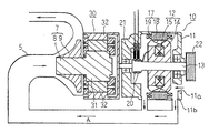
図1はこの発明の実施の形態1に係る車両用過給装置を示すシステム構成図、図2はこの発明の実施の形態1に係る車両用過給装置における動力伝達経路を模式的に示す断面図、図3はこの発明の実施の形態1に係る車両用過給装置に適用される一方向クラッチ付きプーリを示す断面図である。
1 is a system configuration diagram showing a supercharger for a vehicle according to
図1において、エンジン1は、空気が吸気配管5を介して供給され、燃焼後の排気ガスが排気配管6を介して排出される。クランクプーリ3がエンジン1の出力軸であるクランク軸2に固着されている。
In FIG. 1, the
車両用過給装置は、吸気配管5に配設され、エンジン1に供給される空気を圧縮するコンプレッサ7と、電動機能と発電機能とを備え、回転軸13に装着された一方向クラッチ付きプーリ22とクランクプーリ3とに掛け渡された第1ベルト4により、エンジン1の回転駆動力(駆動トルク)が伝達される電動発電機10と、電動発電機10の回転駆動力(駆動トルク)を所定の増速比でコンプレッサ7に伝達する増速機構としての遊星歯車装置30と、電動発電機10とバッテリ35との間で電力を双方向に直流−交流変換するインバータ36と、制御手段としての電子制御ユニット40と、を備えている。インバータ36を構成する複数のスイッチング素子がヒートシンク37上に実装されている。そして、ヒートシンク37が、その放熱フィンを吸気配管5内のコンプレッサ7の上流側に露出するように配設され、スイッチング素子がコンプレッサ7で圧縮される前の高速の吸気流により効果的に冷却される。
The vehicle supercharging device is disposed in the
電子制御ユニット40は、図示していないが、車両の各部から送られてくるデータを受け入れる入力インターフェース、車両の各部の制御を行うための演算を実行するCPU、車両の各部の制御を行うためのプログラムおよび各種のデータが格納されているメモリ、および車両の各部の制御を行うための制御信号を送る出力インターフェースなどを備えている。ここでは、電子制御ユニット40が、各部から送られてくるデータに基づいて、インバータ36のスイッチング素子(図示せず)をON/OFF制御している。
Although not shown, the
つぎに、電動発電機10、遊星歯車装置30およびコンプレッサ7の構成について図2および図3を参照しつつ説明する。
コンプレッサ7は、タービン軸8と、タービン軸8に装着された遠心型ファン形状のタービン9と、を備える、そして、コンプレッサ7はタービン9が装着されたタービン軸8を回転駆動して、空気を圧縮して大気圧以上の圧力で矢印方向に送り込む。
Next, the configuration of the
The
電動発電機10は、ハウジング11の軸心位置に回転自在に支持された回転軸13に固着された回転子12と、この回転子12を囲繞するようにハウジング11に保持された固定子17と、を備える。回転子12は、回転軸13に固着されたランデル型の回転子鉄心14と、回転子鉄心14に巻装された界磁巻線15と、を備える。そして、冷却ファン16が回転子鉄心14の軸方向両端面に固着されている。固定子17は、円筒状の固定子鉄心18と、固定子鉄心18に巻装された電機子巻線19と、を備える。そして、一方向クラッチ付きプーリ22がハウジング11から延出する回転軸13の一端に装着されている。また、界磁巻線15に電流を供給する一対のスリップリング20が、回転軸13の他端側のハウジング11内の部位に固着されている。ブラシ21が、各スリップリング20に摺接するように配設されている。この電動発電機10は、スリップリング20を介して界磁巻線15に流す界磁電流量を調整することにより、回転数範囲が広い用途でも、電圧を一定に保つことができる。
The
一方向クラッチ付きプーリ22は、インナクラッチ23とアウタクラッチ24とが同心状に配置され、楔状空間25がインナクラッチ23とアウタクラッチ24との隙間に周方向に複数形成され、ローラ26が各楔状空間25内に配設され、スプリング27がローラ26を楔状空間25の狭まる方向(図3中反時計回り方向)に付勢するように楔状空間25内に配設されて構成されている。そして、アウタクラッチ24の外周面にV溝が形成され、電動発電機プーリを構成する。つまり、電動発電機プーリがアウタクラッチ24に一体に構成されている。この一方向クラッチ付きプーリ22は、インナクラッチ22を回転軸13に固着して取り付けられ、クランク軸2が電動発電機10に対して駆動側となる時に、インナクラッチ23とアウタクラッチ24とが係合し、電動発電機10がクランク軸2に対して駆動側となる時に、インナクラッチ23とアウタクラッチ24との係合が解除される。
In the
ここで、クランクプーリ3、一方向クラッチ付きプーリ22および第1ベルト4が動力伝達手段を構成している。また、電動発電機プーリはアウタクラッチ24と一体物で構成する必要はなく、別部材で作製し、電動発電機プーリをアウタクラッチに圧入などにより固着して一体化してもよい。
Here, the
遊星歯車装置30は、コンプレッサ7のタービン軸8に連結されたサンギヤ31と、複数のプラネタリギヤ32と、電動発電機10のハウジング11から延出する回転軸13の他端に連結されたリングギヤ33と、を備える。電動発電機10の回転数は、エンジン回転数の2〜3倍程度であるため、最高でも2×10⁴rpm程度までしか上がらない。一方、過給機として有効に動作するためのコンプレッサ7の回転数は、少なくとも4×10⁴〜5×10⁴rpm程度が必要となる。そこで、この遊星歯車装置30は、電動発電機10がリングギヤ33に連結され、プラネタリギヤ32の内周側に配置されたサンギヤ31を出力軸とすることで、増速機として機能し、コンプレッサ7に必要な回転数を確保する。
The
ここで、電動発電機10と遊星歯車装置30とのギヤ比(増速ギヤ比)が大きければ大きいほど、タービン9側が高速化して、過給能力を増すことができる。しかし、タービン軸8には、遠心力や軸受の寿命から速度上限がある。つまり、エンジン最高回転数×クランクプーリ3と一方向クラッチ付きプーリ22とのプーリ比×増速ギヤ比=タービン軸8の限界速度の関係がある。
Here, the larger the gear ratio (speed-up gear ratio) between the
例えば、エンジン最高回転数は、通常、ガソリンエンジン車で6,000rpm、ディーゼルエンジン車で5,000rpmである。また、クランクプーリ3と一方向クラッチ付きプーリ22とのプーリ比は、1:2〜1:3程度である。さらに、通常の軸受を用いた遠心型の過給機として成立するには、タービン軸8の回転数は10×104〜20×104rpm程度が事実上の限界である。従って、増速ギヤ比は、ガソリンエンジン車で5〜17程度、ディーゼルエンジン車で6〜20程度となる。
For example, the maximum engine speed is usually 6,000 rpm for a gasoline engine vehicle and 5,000 rpm for a diesel engine vehicle. The pulley ratio between the
このように構成された車両用過給装置においては、コンプレッサ7を駆動するため駆動手段として既設の電動発電機10を用いており、遊星歯車装置30のサンギヤ31およびリングギヤ33をコンプレッサ7および電動発電機10の2軸に連結しているので、遊星歯車装置30の構造が簡素化され、高度な制御も必要ない。また、一方向クラッチ付きプーリ22を用い、コンプレッサ7を、低速域では電動発電機10で駆動し、高速域ではエンジン1で駆動しているので、電動発電機10に要求される電力が少なくなり、インバータ36およびバッテリ35の大容量化が不要となる。これにより、安価の車両用過給装置を実現できる。
また、電動発電機10がランデル型の車両用電動発電機であり、固定子17の電機子巻線19に通電される電機子電流で電動制御される。そこで、時定数の小さな固定子17への電機子電流で駆動トルクが制御でき、効率の良い駆動トルクと電力の活用ができる。
In the vehicle supercharger configured as described above, the existing
The
また、インバータ36が故障しても、コンプレッサ7がエンジン1で駆動され、運転を継続することができる。
さらに、コンプレッサ7が第1ベルト4を介して伝達されるエンジン1の駆動トルクにより駆動されるので、コンプレッサ7を排ガスの高熱源から遠ざけることができ、コンプレッサ7と電動発電機10との一体化の困難性を排除できる。
Even if the
Further, since the
つぎに、このように構成された車両用過給装置の動作について具体的に説明する。ここでは、エンジン1は、回転数5,000rpmを上限とするディーゼルエンジンであり、クランク軸2と一方向クラッチ付きプーリ22とのプーリ比は3であり、コンプレッサ7の動作が過給機として有効となる回転数が4.5×10⁴rpm程度の遠心型ファン形状のタービンであり、増速ギヤ比を10とする。
Next, the operation of the vehicle supercharger configured as described above will be specifically described. Here, the
[動作1]省エネなどを目的としてエンジン1のアイドリングを停止させた状態から、エンジン1を再始動させる場合。
例えば、エンジン始動釦によるエンジン1の始動操作、あるいは停車時にロックさせた車両停止保持用のサイドブレーキを解除する操作により、エンジン1の始動動作を事前に検知すると、電子制御ユニット40がエンジン再始動を指令として発生させる。これにより、直流モータ式のスタータ、クランク軸2に直結した交流モータなどにより、クランク軸2を回転させてエンジン1を再始動させる。
[Operation 1] When the
For example, when the start operation of the
ここで、クランク軸2の回転速度は、停止状態、若しくは始動直後で数百rpm以下であるので、クランク軸2とタービン軸8とを直接結合している場合には、タービン軸8の回転数が低く、過給動作は期待できない。つまり、タービン軸8の回転数は、過給機として動作するに有効な4.5×10⁴rpm程度を大きく下回る。
そこで、電子制御ユニット40は、スタータ、直結交流モータなどによるクランク軸2の回転動作と同時、若しくは先行して、インバータ36を動作させ、バッテリ35の電力を電動発電機10に供給し、電動発電機10を電動機として動作させる。
Here, since the rotational speed of the
Therefore, the
そして、電動発電機10の回転軸13の回転数を4,500rpm付近まで速度を上げて駆動する。電動発電機10は、増速ギヤ比10の遊星歯車装置30を介してタービン軸8を回転駆動する。これにより、タービン軸8の回転数が4.5×10⁴rpm程度まで上昇し、コンプレッサ7が過給機として動作する。この時、タービン軸8は比較的低速域にあって、電動発電機10がタービン駆動のための駆動トルクより大きな駆動トルクを確保されていれば、電動発電機10の回転軸13の回転数(4,500rpm)が数百rpm(クランク軸2の回転数)×3(プーリ比)より大きくなっても、電動発電機10単独でタービン軸8を駆動可能となり、インナクラッチ23とアウタクラッチ24との係合は解除される。そこで、インナクラッチ23はアウタクラッチ24に対して空転し、エンジン1と電動発電機10との機械的な結合が解除される。
And the rotational speed of the
ここで、電動発電機10で駆動されたタービン9が回転し、吸気配管5を流れる空気の流速が所定値まで迅速に高まる。これにより、吸気配管5内の空気は流動を開始し、空気の慣性により流れは生じている。
そこで、エンジン1の再始動と同時、若しくは再始動直後から、吸気圧を自然吸気状態より高く設定でき、十分な酸素量を確保することができるので、再始動時および再始動直後などの極低速からのアクセル操作に対するエンジン駆動トルクの追従性を確保できる。
Here, the turbine 9 driven by the
Therefore, since the intake pressure can be set higher than the natural intake state at the same time or immediately after the restart of the
また、通常のディーゼルエンジン車では、発進時にエンジン回転数が低いと、電動発電機10の回転数が低く、タービン軸8の回転数が低く、過給圧が不足する。その状態で、アクセル操作により燃料を増量しても、エンジン回転数が上昇して所定の吸気圧に高められるまでは、酸素不足状態となり、黒煙が発生する。しかし、本発明では、アクセル操作による燃料増量やエンジン回転動作に先行して、或いは同時にコンプレッサ7が動作しているので、過給圧が確保されており、酸素不足に起因する黒鉛の発生を最小限に抑制することができる。
Further, in a normal diesel engine vehicle, when the engine speed is low at the time of starting, the
また、アクセル操作による燃料増量やエンジン回転動作に先行して、コンプレッサ7を動作させてタービン軸8の回転数を大きくすることは、加速時間を長く取る手段であり、電動発電機10の回転角加速度を小さくすることによって駆動トルクを低減する作用がある。これにより、インバータ36やバッテリ35の容量を低減でき、低コスト化を図ることができる。
Further, operating the
[動作2]エンジン1の始動直後や車両が信号などで停止した後、エンジン回転数がアイドリング域から加速を行う場合。
通常の車両のアイドリング回転数は500rpm程度である。プーリ比3であると、電動発電機10は1,500rpmで回転し、界磁巻線15への通電量の調整によって発電動作を行っている。つまり、電動発電機10は発電機能で動作している。この状態では、エンジン負荷は小さいので、コンプレッサ7の過給動作は必要ではない。
[Operation 2] Immediately after starting the
The idling speed of a normal vehicle is about 500 rpm. When the pulley ratio is 3, the
ついで、電子制御ユニット40が車両発進時にアクセル操作を検出すると、インバータ36を動作させ、バッテリ35の電力を電動発電機10に供給し、電動発電機10を電動機として動作させる。そして、電動発電機10が所定の過給圧が得られる4,500rpm付近まで駆動される。この時、電動発電機10の回転軸13の回転数がクランク軸2の回転数×プーリ比より大きく、インナクラッチ23とアウタクラッチ24との係合は解除される。そこで、コンプレッサ7は電動発電機10で駆動され、タービン軸8の回転数が上昇し、過給圧が確保される。この過給圧が確保された状態で、エンジン回転数が1,500rpmを超え始めると、タービン軸8の負荷トルクが大きくなり電動発電機10の駆動トルクを超えて、電動発電機10単独でのタービン軸8の駆動が困難となる。その結果、回転軸13の回転数がクランク軸2の回転数×プーリ比より大きくならず、インナクラッチ23とアウタクラッチ24とが係合する。
Next, when the
その後、アクセルON操作が更に継続した場合には、エンジン回転数がさらに増速する。そこで、電子制御ユニット40は、エンジン回転数が1,500rpmを超えると、インバータ36を介して電動発電機10に供給されるバッテリ35の電力を少なくし、電動発電機10の駆動トルクを徐々に低減する。ついには、エンジン1の駆動トルクが電動発電機10の回転軸13に伝達され、エンジン1の駆動トルクがクランク軸2、クランクプーリ3、第1ベルト4、一方向クラッチ付きプーリ22、回転軸13、遊星歯車装置30を介してタービン軸8に伝達される。これにより、コンプレッサ7がエンジン1により駆動される。
Thereafter, when the accelerator ON operation is further continued, the engine speed is further increased. Therefore, when the engine speed exceeds 1,500 rpm, the
ここで、電動発電機10で駆動されたタービン9が回転し、吸気配管5を流れる空気の流速が所定値まで迅速に高まる。これにより、吸気配管5内の空気は流動を開始し、空気の慣性により流れは生じている。
そこで、車両の加速開始時のエンジン回転数が低い状態でも、吸気圧を大気より高く設定でき、十分な酸素量を確保することができるので、発進直後などの極低速からのアクセル操作に対するエンジン駆動トルクの追従性を確保できる。
Here, the turbine 9 driven by the
Therefore, even when the engine speed at the start of acceleration of the vehicle is low, the intake pressure can be set higher than the atmosphere, and a sufficient amount of oxygen can be secured. Torque followability can be secured.
また、通常のディーゼルエンジン車では、発進時にエンジン回転数が低いと、電動発電機10の回転数が低く、タービン軸8の回転数が低く、過給圧が不足する。その状態で、アクセル操作により燃料を増量しても、エンジン回転数が上昇して所定の吸気圧に高められるまでは、酸素不足状態となり、黒煙が発生しやすい状況となる。しかし、この実施の形態1では、アクセル操作による燃料増量やエンジン回転動作に先行して、或いは同時にコンプレッサ7が動作しているので、過給圧が確保されており、酸素不足に起因する黒鉛の発生を最小限に抑制することができる。
Further, in a normal diesel engine vehicle, when the engine speed is low at the time of starting, the
また、エンジン回転数が上昇し始めると、所定のプーリ比で決まる電動発電機10の同期回転数を超えようとする。その際、電動発電機10の加速駆動力を徐々に弱めて行くことで、インナクラッチ23とアウタクラッチ24との係合を滑らかに行うことができる。その結果、インナクラッチ23とアウタクラッチ24との係合時の衝撃力は弱くなり、一方向クラッチ付きプーリ22の摩耗や損傷を低減することができる。
また、特別な切り替え機構を用いることなく、一方向クラッチ付きプーリ22を用いるだけで、コンプレッサ7の駆動を高速域ではエンジン1で駆動し、低速域では電動発電機10で駆動するように切り換えることができ、安価で信頼性の高い過給システムを実現できる。
Further, when the engine speed starts to increase, the engine speed tends to exceed the synchronous speed of the
Further, without using a special switching mechanism, the
この発進時の動作において、コンプレッサ7を高速域ではエンジン1で駆動し、低速域では電動発電機10で駆動しているが、コンプレッサ7を動作させるのに必要な駆動トルクはタービン軸8の回転数の3乗に比例する。
例えば、4,000rpmまでの全域を電動発電機10で駆動すると、電動発電機10を駆動する動力は1,500rpmに対して回転数で2.6倍、駆動出力で19倍と大きな動力が必要となる。コンプレッサ7には数kWクラスの大きな動力を必要とし、そのインバータ36やバッテリ35が大型化する懸念がある。本発明では、エンジン回転数が上昇する高速域ではエンジン1の動力を使用してコンプレッサ7を駆動するので、電動発電機10に求められる駆動トルクは低速域の範囲に限定され、電動発電機10の駆動装置の容量を数百Wクラスまで下げることができる。これにより、インバータ36やバッテリ35の小型化が可能となり、安価で低コストの過給システムが実現できる。
In this starting operation, the
For example, when the
また、インバータ36が故障した場合、電動発電機10によりコンプレッサ7を駆動できない。その場合、タービン軸8の回転数が低い場合から加速しようとすると、エンジン1側からタービン軸8を駆動することになり、インナクラッチ23とアウタクラッチ24とが係合状態となる。そこで、エンジン回転数でアイドリングから1,500rpmの回転付近までの低速域の過給は不十分となるが、急加速時などでエンジン回転数が上昇し、1,500rpmを超えると十分な過給圧が確保される。そこで、インバータ36が故障するという最悪条件でも、部分的な性能低下に留まり、エンジン回転数が1,500rpmを超える高速道路などの走行などは継続できる。従って、修理工場などへの運転を行うことができ、故障時の車両停止や過給不足によって生じる極端な出力低下などの最悪状態を避けることができる。
Further, when the
[動作3]車両加速中の変速機シフトアップの場合。
車両加速時に、運転者が加速を継続する場合、変速機シフトアップ指令動作が発せられ、2速から3速など、ハイギヤ側に変速する。このギヤ変速に伴い、車両では自動変速機および手動変速機のいずれの場合でも、エンジン回転数を瞬間的に低減させ、その後再上昇させてハイギヤ側に合わせる。そして、エンジン回転数が急降下すると、インナクラッチ23とアウタクラッチ24との係合が解除され、電動発電機10とエンジン1との結合が切り離される。そこで、電動発電機10およびコンプレッサ7は回転慣性によって回転を継続し、過給圧が確保される。電子制御ユニット40は、この変速動作時に、電動発電機10が発電機として動作している場合には、発電を停止させる。そして、エンジン回転数が再上昇すると、インナクラッチ23とアウタクラッチ24とが係合し、コンプレッサ7がエンジン1により駆動され、過給圧が確保される。
[Operation 3] In case of transmission shift up during vehicle acceleration.
If the driver continues to accelerate while the vehicle is accelerating, a transmission shift-up command operation is issued and the gear shifts from the second gear to the third gear, such as third gear. Along with this gear shift, in the vehicle, in both the automatic transmission and the manual transmission, the engine speed is instantaneously reduced and then increased again to match the high gear side. When the engine speed drops rapidly, the
ここで、一方向クラッチ付きプーリ22に代えて単なるプーリを用いた場合、タービン軸8の回転数がエンジン回転数の急降下に追従して急降下する。タービン9は吸気配管5中の吸気流速をある程度確保した吸気流にとって吸気抵抗となり吸気ロスを招く。
本発明では、一方向クラッチ付きプーリ22を用いているので、変速機のシフトアップ時におけるエンジン回転数の急降下時に、電動発電機10とエンジン1との結合が切り離される。そこで、電動発電機10およびコンプレッサ7は回転慣性によって高速回転を継続し、上昇した吸気流速を維持し、変速機シフトアップに起因する吸気ロスをなくすことができる。
Here, when a simple pulley is used instead of the
In the present invention, since the
また、電動発電機10とエンジン1との結合が切り離されていても、電動発電機10が発電機として動作していると、発電トルクにより、電動発電機10およびコンプレッサ7の速度が低下してしまう。
本発明では、電動発電機10の発電機としての動作を禁止するので、発電トルクによるコンプレッサ7の速度低下はない。そして、コンプレッサ7の速度は慣性エネルギーにより徐々に低下するものの、変速動作のように短時間であれば、コンプレッサ7は比較的高速回転を維持できる。その結果、エンジン回転数の上昇やコンプレッサ7による過給動作で得た吸気流速を維持することができ、加速時における吸気圧不足をなくすことができる。
Even if the coupling between the
In the present invention, since the operation of the
ディーゼルエンジン車では、スロットルバルブがないため、スロットルバルブの急閉によって生じるタービン9への圧力上昇保護装置(ブローオフバルブ)も不要で、常にある程度の吸気流速を確保することによる障害も少ない。そこで、ディーゼルエンジン車におけるアクセルレスポンス改善効果を得るために本過給装置を採用することは特に有効である。
In a diesel engine vehicle, since there is no throttle valve, there is no need for a pressure rise protection device (blow off valve) for the turbine 9 caused by the sudden closing of the throttle valve , and there are few obstacles due to always ensuring a certain intake flow velocity. Therefore, it is particularly effective to employ this supercharging device in order to obtain an accelerator response improvement effect in a diesel engine vehicle.
[動作4]アクセル加速操作に連動して吸気空気量を調整する吸気側スロットル弁が動作する場合。
車両が加速を完了し、運転者がアクセル操作量を減少して定常速度走行に移行する際、アクセル操作量の減少に起因してエンジン回転数が低下し、電動発電機10の慣性回転によりインナクラッチ23とアウタクラッチ24との係合が解除される。そこで、電子制御ユニット40が、車両の加速が完了し、アクセル操作量の減少を検知すると、吸気側スロットル弁を開方向に動作させると同時に、電動発電機10を発電機として駆動する。
その後、運転者がアクセル操作量を増加させ、車両を加速させると、電動発電機10を電動機として駆動し、コンプレッサ7を回転駆動し、過給圧を確保する。そして、エンジン回転数が上昇すると、電動発電機10の電動機として動作を停止するとともに、インナクラッチ23とアウタクラッチ24とが係合し、コンプレッサ7がエンジン1により駆動される。
[Operation 4] When the intake side throttle valve that adjusts the intake air amount operates in conjunction with the accelerator acceleration operation.
When the vehicle completes acceleration and the driver decreases the accelerator operation amount and shifts to steady speed driving, the engine speed decreases due to the decrease in the accelerator operation amount, and the inner speed is increased by the inertia rotation of the
Thereafter, when the driver increases the accelerator operation amount and accelerates the vehicle, the
エンジン回転数が上昇し、吸気流速が速い領域においては、加速が完了して定常速度走行に移行する際に吸気側スロットル弁を閉じると、吸気抵抗が発生し、通常ガソリン式エンジンではポンピングロスが生じる。
本発明では、吸気側スロットル弁を開いて吸気抵抗を最小にしつつ、電動発電機10を発電機として動作させる。これにより、コンプレッサ7の駆動トルクが電動発電機10で電気エネルギーに変換され、タービン軸8の回転数が減少する。つまり、コンプレッサ7が回生制動され、吸気抵抗がタービン9により増大し、吸気量が制限される。このように、スロットルで捨てられていたポンピングエネルギーを電力として回生できる。
In the region where the engine speed increases and the intake air flow velocity is high, if the intake side throttle valve is closed when the acceleration is completed and the vehicle shifts to steady speed driving, an intake resistance is generated. Arise.
In the present invention, the
実施の形態2.
図4はこの発明の実施の形態2に係る車両用過給装置を示すシステム構成図である。
図4において、第1プーリ41が一方向クラッチ付きプーリ22と並んで回転軸13に固着されている。オイルポンプ42は、回転軸43に固着された第2プーリ44を備え、遊星歯車装置30にオイルを供給して潤滑する。そして、第2ベルト45が第1および第2プーリ41,44に掛け渡され、電動発電機10の駆動トルクがオイルポンプ42に伝達される。
なお、他の構成は上記実施の形態1と同様に構成されている。
FIG. 4 is a system configuration diagram showing a vehicle supercharging device according to
In FIG. 4, the
Other configurations are the same as those in the first embodiment.
この実施の形態2によれば、エンジン1の停止時に、電動発電機10を電動機として動作させることで、オイルポンプ42を駆動できる。そこで、電動発電機10でコンプレッサ7を高速駆動する際には、オイルポンプ42から遊星歯車装置30に常に給油され、遊星歯車装置30での潤滑不足による故障の発生を未然に回避することができる。
According to the second embodiment, the
実施の形態3.
図5はこの発明の実施の形態3に係る車両用過給装置を示すシステム構成図、図6はこの発明の実施の形態3に係る車両用過給装置における動力伝達経路を模式的に示す断面図である。
図5および図6において、電動発電機10のハウジング11には、吸気孔11aと排気孔11bとが設けられ、吸気配管5のコンプレッサ7の上流側が排気孔11bに連結されている。これにより、コンプレッサ7の駆動によって、空気が吸気孔11aからハウジング11内に吸入され、回転子12および固定子17を冷却した後ハウジング11の排気孔11bから排出され、吸気配管5内を流通してコンプレッサ7に供給される吸気流Aが形成される。
なお、他の構成は、上記実施の形態1と同様に構成されている。
FIG. 5 is a system configuration diagram showing a vehicular supercharging device according to
5 and 6, the
Other configurations are the same as those in the first embodiment.
この実施の形態3によれば、回転子12および固定子17がコンプレッサ7の駆動によって得られる吸気流Aにより冷却されるので、冷却ファン16が不要となり、電動発電機10の軸方向サイズを縮小できる。これにより、遊星歯車装置30およびコンプレッサ7を電動発電機10の反負荷側に取り付けることに起因する軸方向サイズの増大をある程度相殺でき、過給装置の狭いエンジンルームなどへの搭載性を向上できる。
また、電動発電機10の発電電力を整流するダイオードブリッジをスイッチング素子とともにインバータ36に組み込むことで、ハウジング11内の反負荷側に取り付けられる整流装置などの部品が省略でき、電動発電機10の軸方向サイズの一層の縮小化が図られる。
According to the third embodiment, since the
Further, by incorporating a diode bridge for rectifying the power generated by the
なお、上記各実施の形態では、電動発電機10は界磁式の回転子12を用いるものとしているが、界磁式の回転子12に代えて永久磁石式の回転子を用いてもよい。この場合、スリップリング20やブラシ21等が不要となるとともに、インバータ36の容量を削減することができる。
また、上記各実施の形態では、増速機構として遊星歯車装置30を用いるものとしているが、増速機構は遊星歯車装置30に限定されるものではなく、例えば遊星ローラ装置を用いてもよい。
In each of the above embodiments, the
In each of the above embodiments, the
1 エンジン、2 クランク軸、3 クランクプーリ(動力伝達手段)、4 第1ベルト(動力伝達手段)、5 吸気配管、7 コンプレッサ、8 タービン軸、9 タービン、10 電動発電機、11 ハウジング、11a 吸気孔、11b 排気孔、12 回転子、13 回転軸、17 固定子、19 電機子巻線、22 一方向クラッチ付きプーリ(動力伝達手段)、24 アウタクラッチ(電動発電機プーリ)、30 遊星歯車装置(増速機構)、35 バッテリ、36 インバータ、37 ヒートシンク、40 電子制御ユニット(制御手段)、41 第1プーリ、42 オイルポンプ、44 第2プーリ、45 第2ベルト。 1 engine, 2 crankshaft, 3 crank pulley (power transmission means), 4 first belt (power transmission means), 5 intake pipe, 7 compressor, 8 turbine shaft, 9 turbine, 10 motor generator, 11 housing, 11a intake air Hole, 11b Exhaust hole, 12 Rotor, 13 Rotating shaft, 17 Stator, 19 Armature winding, 22 One-way clutch pulley (power transmission means), 24 Outer clutch (motor generator pulley), 30 Planetary gear unit (Speed increasing mechanism), 35 battery, 36 inverter, 37 heat sink, 40 electronic control unit (control means), 41 first pulley, 42 oil pump, 44 second pulley, 45 second belt.
Claims (6)
上記動力伝達手段は、上記エンジンのクランク軸に装着されたクランクプーリと、上記電動発電機の回転軸に装着された一方向クラッチ付プーリと、上記クランクプーリと上記一方向クラッチ付プーリとに掛け渡された第1ベルトと、を有し、
上記一方向クラッチ付きプーリは、上記電動発電機の回転軸の駆動トルクが上記コンプレッサのタービン軸の負荷トルクより大きい場合に、上記エンジンのクランク軸と上記電動発電機の回転軸とが相対的に非結合状態動作となり、上記電動発電機の回転軸の駆動トルクが上記コンプレッサのタービン軸の負荷トルクより小さい場合に、上記エンジンのクランク軸と上記電動発電機の回転軸とが相対的に結合状態動作となるように構成され、
上記制御手段は、エンジン回転数が所定値以下の場合に、上記インバータを制御して上記電動発電機を電動機として駆動し、上記コンプレッサを該電動発電機により駆動させるように構成され、
上記電動発電機の回転軸に固着された第1プーリと、上記増速機構を潤滑するオイルポンプと、該オイルポンプの回転軸に固着された第2プーリと、上記第1プーリと上記第2プーリとの間に掛け渡された第2ベルトと、をさらに備えていることを特徴とする車両用過給装置。 An engine, a motor generator having a power generation function and an electric function, a compressor disposed in an intake pipe of the engine, and a power for transmitting a driving torque of a crankshaft of the engine to a rotating shaft of the motor generator Electric power is transmitted between the transmission means, the speed increasing mechanism for transmitting the driving torque of the rotating shaft of the motor generator to the turbine shaft of the compressor at a predetermined speed increasing ratio, the battery, and the motor generator and the battery. In a supercharger for a vehicle comprising an inverter for DC-AC conversion and a control means for controlling the inverter,
Said power transmission means, subjected to a crank pulley attached to a crankshaft of the engine, a pulley with a one-way clutch which is mounted on the rotary shaft of the electric generator, and the pulley with the crankshaft pulley and the one-way clutch a first and a belt passed, and
In the pulley with one-way clutch, when the driving torque of the rotating shaft of the motor generator is larger than the load torque of the turbine shaft of the compressor, the crank shaft of the engine and the rotating shaft of the motor generator are relatively When the driving torque of the rotating shaft of the motor generator is smaller than the load torque of the turbine shaft of the compressor, the crank shaft of the engine and the rotating shaft of the motor generator are relatively connected when the motor generator is driven in a non-coupled state. Configured to work,
The control means is configured to control the inverter to drive the motor generator as a motor when the engine speed is equal to or lower than a predetermined value, and to drive the compressor by the motor generator ,
A first pulley fixed to the rotating shaft of the motor generator; an oil pump for lubricating the speed increasing mechanism; a second pulley fixed to the rotating shaft of the oil pump; the first pulley and the second pulley; A vehicular supercharging device , further comprising: a second belt hung between the pulleys .
Priority Applications (2)
| Application Number | Priority Date | Filing Date | Title |
|---|---|---|---|
| JP2008132251A JP4491490B2 (en) | 2007-07-18 | 2008-05-20 | Supercharger for vehicle |
| US12/170,050 US8087401B2 (en) | 2007-07-18 | 2008-07-09 | Automotive supercharging apparatus |
Applications Claiming Priority (2)
| Application Number | Priority Date | Filing Date | Title |
|---|---|---|---|
| JP2007186882 | 2007-07-18 | ||
| JP2008132251A JP4491490B2 (en) | 2007-07-18 | 2008-05-20 | Supercharger for vehicle |
Related Child Applications (1)
| Application Number | Title | Priority Date | Filing Date |
|---|---|---|---|
| JP2009229345A Division JP2010001896A (en) | 2007-07-18 | 2009-10-01 | Vehicular supercharging apparatus |
Publications (2)
| Publication Number | Publication Date |
|---|---|
| JP2009041556A JP2009041556A (en) | 2009-02-26 |
| JP4491490B2 true JP4491490B2 (en) | 2010-06-30 |
Family
ID=40442534
Family Applications (2)
| Application Number | Title | Priority Date | Filing Date |
|---|---|---|---|
| JP2008132251A Active JP4491490B2 (en) | 2007-07-18 | 2008-05-20 | Supercharger for vehicle |
| JP2009229345A Pending JP2010001896A (en) | 2007-07-18 | 2009-10-01 | Vehicular supercharging apparatus |
Family Applications After (1)
| Application Number | Title | Priority Date | Filing Date |
|---|---|---|---|
| JP2009229345A Pending JP2010001896A (en) | 2007-07-18 | 2009-10-01 | Vehicular supercharging apparatus |
Country Status (1)
| Country | Link |
|---|---|
| JP (2) | JP4491490B2 (en) |
Families Citing this family (14)
| Publication number | Priority date | Publication date | Assignee | Title |
|---|---|---|---|---|
| DE102009045624B4 (en) | 2009-10-13 | 2021-12-02 | Ford Global Technologies, Llc | Generator coupled with an air compressor |
| JP5174073B2 (en) | 2010-03-18 | 2013-04-03 | 三菱重工業株式会社 | Electric supercharger |
| JP5691402B2 (en) * | 2010-10-28 | 2015-04-01 | いすゞ自動車株式会社 | Electric assist turbocharger |
| JP2012092799A (en) * | 2010-10-28 | 2012-05-17 | Isuzu Motors Ltd | Electrically-assisted turbocharger |
| JP5433643B2 (en) * | 2011-07-15 | 2014-03-05 | 三菱重工業株式会社 | Electric supercharging device and multistage supercharging system |
| JP5587859B2 (en) | 2011-12-28 | 2014-09-10 | 三菱重工業株式会社 | Electric supercharger |
| GB201210679D0 (en) | 2012-06-15 | 2012-08-01 | Jaguar Cars | Supercharger drive |
| US10072667B2 (en) | 2012-11-22 | 2018-09-11 | Mitsubishi Heavy Industries Engine & Turbocharger, Ltd. | Supercharger with electric motor and engine device provided with supercharger with electric motor |
| CN102953808A (en) * | 2012-11-30 | 2013-03-06 | 中国人民解放军后勤工程学院 | Power takeoff device for oxygen-rich auxiliary combustion device of engine |
| US9776625B2 (en) * | 2014-04-22 | 2017-10-03 | Panasonic Intellectual Property Management Co., Ltd. | Vehicle drive device |
| CN107060994A (en) * | 2017-01-23 | 2017-08-18 | 重庆城市管理职业学院 | Engine turbine supercharging device |
| JP6686964B2 (en) * | 2017-04-27 | 2020-04-22 | トヨタ自動車株式会社 | Mechanical supercharging system |
| WO2020204568A1 (en) * | 2019-04-01 | 2020-10-08 | 김관현 | Positive displacement turbine engine |
| CN113492825B (en) * | 2021-06-29 | 2022-12-20 | 东风汽车集团股份有限公司 | Vehicle control assembly, method and device and vehicle |
Citations (4)
| Publication number | Priority date | Publication date | Assignee | Title |
|---|---|---|---|---|
| JPH11173154A (en) * | 1997-12-09 | 1999-06-29 | Tochigi Fuji Ind Co Ltd | Mechanical supercharger |
| JP2001289051A (en) * | 2000-04-03 | 2001-10-19 | Ishikawajima Harima Heavy Ind Co Ltd | Device and method for preventing tooth hitting sound of mechanical supercharger |
| JP2001323818A (en) * | 2000-05-16 | 2001-11-22 | Nissan Motor Co Ltd | Engine having supercharger |
| JP2003314446A (en) * | 2002-04-23 | 2003-11-06 | Nsk Ltd | High-speed fluid device |
Family Cites Families (2)
| Publication number | Priority date | Publication date | Assignee | Title |
|---|---|---|---|---|
| JPH08266097A (en) * | 1995-03-27 | 1996-10-11 | Daihatsu Motor Co Ltd | Control method of alternator |
| EP1054789B1 (en) * | 1998-12-15 | 2004-03-17 | Robert Bosch Gmbh | Method for switching consumers on or off |
-
2008
- 2008-05-20 JP JP2008132251A patent/JP4491490B2/en active Active
-
2009
- 2009-10-01 JP JP2009229345A patent/JP2010001896A/en active Pending
Patent Citations (4)
| Publication number | Priority date | Publication date | Assignee | Title |
|---|---|---|---|---|
| JPH11173154A (en) * | 1997-12-09 | 1999-06-29 | Tochigi Fuji Ind Co Ltd | Mechanical supercharger |
| JP2001289051A (en) * | 2000-04-03 | 2001-10-19 | Ishikawajima Harima Heavy Ind Co Ltd | Device and method for preventing tooth hitting sound of mechanical supercharger |
| JP2001323818A (en) * | 2000-05-16 | 2001-11-22 | Nissan Motor Co Ltd | Engine having supercharger |
| JP2003314446A (en) * | 2002-04-23 | 2003-11-06 | Nsk Ltd | High-speed fluid device |
Also Published As
| Publication number | Publication date |
|---|---|
| JP2009041556A (en) | 2009-02-26 |
| JP2010001896A (en) | 2010-01-07 |
Similar Documents
| Publication | Publication Date | Title |
|---|---|---|
| JP4491490B2 (en) | Supercharger for vehicle | |
| US8087401B2 (en) | Automotive supercharging apparatus | |
| KR102053538B1 (en) | Apparatus and method for operating accessories of vehicle during engine stop using one-way clutch pulley | |
| JP6185555B2 (en) | Variable speed hybrid electric supercharger assembly and vehicle control method having the same | |
| US6878094B2 (en) | Power transmission control device for vehicle | |
| US8221284B2 (en) | Automotive drive apparatus | |
| US8622862B2 (en) | Power transmitting device | |
| US7063641B2 (en) | Dynamo-electric drive unit controlled compound power system | |
| TWI439382B (en) | Hybrid propulsion and transmission system for motorcycles | |
| CA2987227A1 (en) | Hybrid-electric drive system | |
| GB2429500A (en) | Motor/generator having a gear arrangement with two parallel overrunning clutches | |
| WO2012081272A1 (en) | Hybrid vehicle | |
| JP2010083230A (en) | Hybrid drive device | |
| US6936933B2 (en) | Hybrid propulsion system for a motor vehicle | |
| WO2013091669A1 (en) | A turbo compound transmission and a method for controlling a turbo compound transmission | |
| JP3847720B2 (en) | Auxiliary drive device for internal combustion engine | |
| KR20160037937A (en) | Dual clutch powertrain architecture | |
| US9599198B2 (en) | Device for transmitting mechanical torque between a driving member and a driven member, and air-compression system for supplying power to an engine using such a device | |
| TW200525097A (en) | One-way clutch device and motorcycle using the same | |
| KR101272591B1 (en) | Air conditioner driving system of hybrid electric vehicle | |
| JP2004124815A (en) | Belt power transmission device for vehicle | |
| WO2010067673A1 (en) | Roller clutch device, and starter and engine start device both using same | |
| JP4168343B2 (en) | Auxiliary drive engine starter | |
| KR100513522B1 (en) | Power train system of hybrid electric vehicle | |
| JP3706688B2 (en) | Combined prime mover and its control device |
Legal Events
| Date | Code | Title | Description |
|---|---|---|---|
| A621 | Written request for application examination |
Free format text: JAPANESE INTERMEDIATE CODE: A621 Effective date: 20090202 |
|
| A977 | Report on retrieval |
Free format text: JAPANESE INTERMEDIATE CODE: A971007 Effective date: 20090723 |
|
| A131 | Notification of reasons for refusal |
Free format text: JAPANESE INTERMEDIATE CODE: A131 Effective date: 20090804 |
|
| A521 | Written amendment |
Free format text: JAPANESE INTERMEDIATE CODE: A523 Effective date: 20091001 |
|
| TRDD | Decision of grant or rejection written | ||
| A01 | Written decision to grant a patent or to grant a registration (utility model) |
Free format text: JAPANESE INTERMEDIATE CODE: A01 Effective date: 20100316 |
|
| A01 | Written decision to grant a patent or to grant a registration (utility model) |
Free format text: JAPANESE INTERMEDIATE CODE: A01 |
|
| A61 | First payment of annual fees (during grant procedure) |
Free format text: JAPANESE INTERMEDIATE CODE: A61 Effective date: 20100405 |
|
| FPAY | Renewal fee payment (event date is renewal date of database) |
Free format text: PAYMENT UNTIL: 20130409 Year of fee payment: 3 |
|
| R150 | Certificate of patent or registration of utility model |
Free format text: JAPANESE INTERMEDIATE CODE: R150 |
|
| FPAY | Renewal fee payment (event date is renewal date of database) |
Free format text: PAYMENT UNTIL: 20130409 Year of fee payment: 3 |
|
| FPAY | Renewal fee payment (event date is renewal date of database) |
Free format text: PAYMENT UNTIL: 20140409 Year of fee payment: 4 |
|
| R250 | Receipt of annual fees |
Free format text: JAPANESE INTERMEDIATE CODE: R250 |
|
| R250 | Receipt of annual fees |
Free format text: JAPANESE INTERMEDIATE CODE: R250 |
|
| R250 | Receipt of annual fees |
Free format text: JAPANESE INTERMEDIATE CODE: R250 |
|
| R250 | Receipt of annual fees |
Free format text: JAPANESE INTERMEDIATE CODE: R250 |