JP4491230B2 - Method and apparatus for manufacturing a model of a three-dimensional object - Google Patents
Method and apparatus for manufacturing a model of a three-dimensional object Download PDFInfo
- Publication number
- JP4491230B2 JP4491230B2 JP2003520600A JP2003520600A JP4491230B2 JP 4491230 B2 JP4491230 B2 JP 4491230B2 JP 2003520600 A JP2003520600 A JP 2003520600A JP 2003520600 A JP2003520600 A JP 2003520600A JP 4491230 B2 JP4491230 B2 JP 4491230B2
- Authority
- JP
- Japan
- Prior art keywords
- binder
- printhead
- binder solution
- dimensional object
- Prior art date
- Legal status (The legal status is an assumption and is not a legal conclusion. Google has not performed a legal analysis and makes no representation as to the accuracy of the status listed.)
- Expired - Lifetime
Links
Images


Classifications
-
- B—PERFORMING OPERATIONS; TRANSPORTING
- B41—PRINTING; LINING MACHINES; TYPEWRITERS; STAMPS
- B41J—TYPEWRITERS; SELECTIVE PRINTING MECHANISMS, i.e. MECHANISMS PRINTING OTHERWISE THAN FROM A FORME; CORRECTION OF TYPOGRAPHICAL ERRORS
- B41J2/00—Typewriters or selective printing mechanisms characterised by the printing or marking process for which they are designed
- B41J2/005—Typewriters or selective printing mechanisms characterised by the printing or marking process for which they are designed characterised by bringing liquid or particles selectively into contact with a printing material
- B41J2/01—Ink jet
- B41J2/135—Nozzles
- B41J2/165—Preventing or detecting of nozzle clogging, e.g. cleaning, capping or moistening for nozzles
- B41J2/16517—Cleaning of print head nozzles
- B41J2/16552—Cleaning of print head nozzles using cleaning fluids
-
- B—PERFORMING OPERATIONS; TRANSPORTING
- B29—WORKING OF PLASTICS; WORKING OF SUBSTANCES IN A PLASTIC STATE IN GENERAL
- B29C—SHAPING OR JOINING OF PLASTICS; SHAPING OF MATERIAL IN A PLASTIC STATE, NOT OTHERWISE PROVIDED FOR; AFTER-TREATMENT OF THE SHAPED PRODUCTS, e.g. REPAIRING
- B29C41/00—Shaping by coating a mould, core or other substrate, i.e. by depositing material and stripping-off the shaped article; Apparatus therefor
- B29C41/02—Shaping by coating a mould, core or other substrate, i.e. by depositing material and stripping-off the shaped article; Apparatus therefor for making articles of definite length, i.e. discrete articles
- B29C41/12—Spreading-out the material on a substrate, e.g. on the surface of a liquid
-
- B—PERFORMING OPERATIONS; TRANSPORTING
- B29—WORKING OF PLASTICS; WORKING OF SUBSTANCES IN A PLASTIC STATE IN GENERAL
- B29C—SHAPING OR JOINING OF PLASTICS; SHAPING OF MATERIAL IN A PLASTIC STATE, NOT OTHERWISE PROVIDED FOR; AFTER-TREATMENT OF THE SHAPED PRODUCTS, e.g. REPAIRING
- B29C64/00—Additive manufacturing, i.e. manufacturing of three-dimensional [3D] objects by additive deposition, additive agglomeration or additive layering, e.g. by 3D printing, stereolithography or selective laser sintering
- B29C64/10—Processes of additive manufacturing
- B29C64/165—Processes of additive manufacturing using a combination of solid and fluid materials, e.g. a powder selectively bound by a liquid binder, catalyst, inhibitor or energy absorber
-
- B—PERFORMING OPERATIONS; TRANSPORTING
- B29—WORKING OF PLASTICS; WORKING OF SUBSTANCES IN A PLASTIC STATE IN GENERAL
- B29C—SHAPING OR JOINING OF PLASTICS; SHAPING OF MATERIAL IN A PLASTIC STATE, NOT OTHERWISE PROVIDED FOR; AFTER-TREATMENT OF THE SHAPED PRODUCTS, e.g. REPAIRING
- B29C64/00—Additive manufacturing, i.e. manufacturing of three-dimensional [3D] objects by additive deposition, additive agglomeration or additive layering, e.g. by 3D printing, stereolithography or selective laser sintering
- B29C64/30—Auxiliary operations or equipment
- B29C64/35—Cleaning
-
- B—PERFORMING OPERATIONS; TRANSPORTING
- B29—WORKING OF PLASTICS; WORKING OF SUBSTANCES IN A PLASTIC STATE IN GENERAL
- B29C—SHAPING OR JOINING OF PLASTICS; SHAPING OF MATERIAL IN A PLASTIC STATE, NOT OTHERWISE PROVIDED FOR; AFTER-TREATMENT OF THE SHAPED PRODUCTS, e.g. REPAIRING
- B29C64/00—Additive manufacturing, i.e. manufacturing of three-dimensional [3D] objects by additive deposition, additive agglomeration or additive layering, e.g. by 3D printing, stereolithography or selective laser sintering
- B29C64/30—Auxiliary operations or equipment
- B29C64/357—Recycling
-
- B—PERFORMING OPERATIONS; TRANSPORTING
- B29—WORKING OF PLASTICS; WORKING OF SUBSTANCES IN A PLASTIC STATE IN GENERAL
- B29C—SHAPING OR JOINING OF PLASTICS; SHAPING OF MATERIAL IN A PLASTIC STATE, NOT OTHERWISE PROVIDED FOR; AFTER-TREATMENT OF THE SHAPED PRODUCTS, e.g. REPAIRING
- B29C64/00—Additive manufacturing, i.e. manufacturing of three-dimensional [3D] objects by additive deposition, additive agglomeration or additive layering, e.g. by 3D printing, stereolithography or selective laser sintering
- B29C64/30—Auxiliary operations or equipment
- B29C64/386—Data acquisition or data processing for additive manufacturing
- B29C64/393—Data acquisition or data processing for additive manufacturing for controlling or regulating additive manufacturing processes
-
- B—PERFORMING OPERATIONS; TRANSPORTING
- B33—ADDITIVE MANUFACTURING TECHNOLOGY
- B33Y—ADDITIVE MANUFACTURING, i.e. MANUFACTURING OF THREE-DIMENSIONAL [3-D] OBJECTS BY ADDITIVE DEPOSITION, ADDITIVE AGGLOMERATION OR ADDITIVE LAYERING, e.g. BY 3-D PRINTING, STEREOLITHOGRAPHY OR SELECTIVE LASER SINTERING
- B33Y10/00—Processes of additive manufacturing
-
- B—PERFORMING OPERATIONS; TRANSPORTING
- B33—ADDITIVE MANUFACTURING TECHNOLOGY
- B33Y—ADDITIVE MANUFACTURING, i.e. MANUFACTURING OF THREE-DIMENSIONAL [3-D] OBJECTS BY ADDITIVE DEPOSITION, ADDITIVE AGGLOMERATION OR ADDITIVE LAYERING, e.g. BY 3-D PRINTING, STEREOLITHOGRAPHY OR SELECTIVE LASER SINTERING
- B33Y30/00—Apparatus for additive manufacturing; Details thereof or accessories therefor
-
- B—PERFORMING OPERATIONS; TRANSPORTING
- B33—ADDITIVE MANUFACTURING TECHNOLOGY
- B33Y—ADDITIVE MANUFACTURING, i.e. MANUFACTURING OF THREE-DIMENSIONAL [3-D] OBJECTS BY ADDITIVE DEPOSITION, ADDITIVE AGGLOMERATION OR ADDITIVE LAYERING, e.g. BY 3-D PRINTING, STEREOLITHOGRAPHY OR SELECTIVE LASER SINTERING
- B33Y40/00—Auxiliary operations or equipment, e.g. for material handling
-
- B—PERFORMING OPERATIONS; TRANSPORTING
- B41—PRINTING; LINING MACHINES; TYPEWRITERS; STAMPS
- B41J—TYPEWRITERS; SELECTIVE PRINTING MECHANISMS, i.e. MECHANISMS PRINTING OTHERWISE THAN FROM A FORME; CORRECTION OF TYPOGRAPHICAL ERRORS
- B41J2/00—Typewriters or selective printing mechanisms characterised by the printing or marking process for which they are designed
- B41J2/005—Typewriters or selective printing mechanisms characterised by the printing or marking process for which they are designed characterised by bringing liquid or particles selectively into contact with a printing material
- B41J2/01—Ink jet
-
- H—ELECTRICITY
- H04—ELECTRIC COMMUNICATION TECHNIQUE
- H04N—PICTORIAL COMMUNICATION, e.g. TELEVISION
- H04N1/00—Scanning, transmission or reproduction of documents or the like, e.g. facsimile transmission; Details thereof
- H04N1/46—Colour picture communication systems
- H04N1/56—Processing of colour picture signals
- H04N1/58—Edge or detail enhancement; Noise or error suppression, e.g. colour misregistration correction
-
- B—PERFORMING OPERATIONS; TRANSPORTING
- B29—WORKING OF PLASTICS; WORKING OF SUBSTANCES IN A PLASTIC STATE IN GENERAL
- B29K—INDEXING SCHEME ASSOCIATED WITH SUBCLASSES B29B, B29C OR B29D, RELATING TO MOULDING MATERIALS OR TO MATERIALS FOR MOULDS, REINFORCEMENTS, FILLERS OR PREFORMED PARTS, e.g. INSERTS
- B29K2995/00—Properties of moulding materials, reinforcements, fillers, preformed parts or moulds
- B29K2995/0018—Properties of moulding materials, reinforcements, fillers, preformed parts or moulds having particular optical properties, e.g. fluorescent or phosphorescent
- B29K2995/002—Coloured
- B29K2995/0021—Multi-coloured
-
- B—PERFORMING OPERATIONS; TRANSPORTING
- B41—PRINTING; LINING MACHINES; TYPEWRITERS; STAMPS
- B41J—TYPEWRITERS; SELECTIVE PRINTING MECHANISMS, i.e. MECHANISMS PRINTING OTHERWISE THAN FROM A FORME; CORRECTION OF TYPOGRAPHICAL ERRORS
- B41J2/00—Typewriters or selective printing mechanisms characterised by the printing or marking process for which they are designed
- B41J2/005—Typewriters or selective printing mechanisms characterised by the printing or marking process for which they are designed characterised by bringing liquid or particles selectively into contact with a printing material
- B41J2/01—Ink jet
- B41J2/135—Nozzles
- B41J2/165—Preventing or detecting of nozzle clogging, e.g. cleaning, capping or moistening for nozzles
- B41J2/16517—Cleaning of print head nozzles
- B41J2/16535—Cleaning of print head nozzles using wiping constructions
- B41J2/16541—Means to remove deposits from wipers or scrapers
Abstract
Description
本発明は、ラピッド・プロトタイピング、特にプリンタを用いるインクジェット法により、3次元物体の模型を制作する方法および装置に関するものである。 The present invention relates to a method and an apparatus for producing a model of a three-dimensional object by rapid prototyping, particularly an ink jet method using a printer.
ラピッド・プロトタイピング(rapid prototyping)とは、対象物のコンピュータ・モデルからその対象物の3次元模型を製作するさまざまな方法のことである。1つの方法は3次元プリントである。これは、特殊なプリンタを使用して、複数の2次元層から立体模型を製作するものである。詳細には、3D対象物のディジタル表現をコンピュータ・メモリに格納する。コンピュータ・ソフトウェアはそのディジタル表現を複数の別個の2D層に分割する。次に、3Dプリンタは、ソフトウェアで分割された各層毎に材料層を加工する。複数の加工された層が積層されて、所望の模型が造形される。 Rapid prototyping is a variety of methods for creating a three-dimensional model of an object from a computer model of the object. One method is three-dimensional printing. In this method, a three-dimensional model is produced from a plurality of two-dimensional layers using a special printer. Specifically, a digital representation of the 3D object is stored in computer memory. Computer software divides the digital representation into multiple separate 2D layers. Next, the 3D printer processes a material layer for each layer divided by software. A plurality of processed layers are stacked to form a desired model.
3次元プリントの1つの方法では、粉末材料の層が限られた領域に堆積される。各層の上に結合剤溶液を選択的に滴下し、堆積させて、結合された粉末の領域を形成する。その後、結合されなかった粉末を除去して、3次元造形物を形成する。 In one method of three-dimensional printing, a layer of powder material is deposited in a limited area. A binder solution is selectively dropped onto each layer and deposited to form a bonded powder region. Thereafter, the unbonded powder is removed to form a three-dimensional structure.
本発明は、粉末の造形材料のような物質から3次元物体を製作するためのシステムを提供する。液体結合剤のような第2の材料を使用して造形材料を特定の箇所で結合させることにより、3次元物体を形成する。 The present invention provides a system for making a three-dimensional object from a substance such as a powdered building material. A three-dimensional object is formed by bonding a build material at a specific location using a second material such as a liquid binder.
本発明の1つの構成によれば、3次元プリンタは、結合剤溶液を造形チャンバ内の造形材料のベッド上にプリントするための複数のプリントヘッドを備える。この結合剤溶液は、着色剤と混合された結合剤からなる着色結合剤溶液である。プリントヘッドは、造形チャンバを横断して低速軸に沿って往復移動するように設計されたガントリ上に取り付けされる。さらに、プリントヘッドはガントリ全体にわたって高速軸上を往復運動するので、高速軸および低速軸の両方に沿って移動でき、それにより、(着色された)結合剤溶液を造形チャンバ内の造形材料のベッドの表面全体に滴下し、堆積できる。 According to one configuration of the invention, the three-dimensional printer comprises a plurality of print heads for printing a binder solution onto a bed of build material in a build chamber. This binder solution is a colored binder solution consisting of a binder mixed with a colorant. The printhead is mounted on a gantry designed to reciprocate along the slow axis across the build chamber. Furthermore, the print head reciprocates on the high speed axis throughout the gantry so that it can move along both the high speed axis and the low speed axis, thereby allowing the (colored) binder solution to flow through the bed of build material in the build chamber. Can be dripped and deposited on the entire surface of the substrate.
プリントヘッドが高速軸に沿って造形材料のベッドを横断して通過する毎に、プリントヘッドは低速軸に沿って1段階進行し、その後、再度高速軸に沿ってベッドを横断して通過する。造形材料のベッド上に1つの層全体がプリントされるまで、この工程を繰り返す。次に、その層の上に別の層を同一工程により堆積できる。 Each time the print head passes across the bed of build material along the fast axis, the print head advances one step along the slow axis and then again passes across the bed along the fast axis. This process is repeated until an entire layer is printed on the bed of build material. Next, another layer can be deposited on the layer by the same process.
ガントリ上で、プリントヘッドを低速軸の方向に互いにずらすことができる。この構成により、プリントヘッドは、高速軸に沿って造形材料のベッドを横断して通過するときに、造形材料のベッド全体に隣り合うラインまたは重複ラインをプリントできるので、プリントヘッドが造形材料のベッドを横断して通過する毎に、着色結合剤溶液を含む結合剤溶液の幅広いバンド状のラインをベッド上にプリントできる。各プリントヘッドは、結合剤溶液のみか、または着色剤と混合した結合剤溶液をプリントできる。 On the gantry, the print heads can be shifted from one another in the direction of the slow axis. This configuration allows the printhead to print adjacent or overlapping lines across the entire bed of build material as it passes across the bed of build material along the high speed axis so that the printhead can be printed on the bed of build material. A wide band-like line of binder solution, including colored binder solution, can be printed on the bed each time it passes across. Each print head can print a binder solution alone or mixed with a colorant.
3次元物体を製作するこのシステムを使用して、着色された物体を造形できる。さらに、複数のプリントヘッドを使用して、造形材料に結合剤溶液をプリントできる。 Using this system for producing 3D objects, colored objects can be shaped. In addition, a plurality of printheads can be used to print the binder solution on the build material.
別の構成によれば、プリントヘッドはそれぞれ、複数の外部結合剤供給源に接続できる。例えば、少なくとも3つのプリントヘッドのそれぞれは3原色(シアン、イエロー、マゼンタ)のうちの一色またはブラックを有する異なる着色剤に接続できる。外部結合剤供給源もまた、プリントヘッドのそれぞれに接続でき、さらに少なくとも1つの別のプリントヘッドを設けて、結合剤溶液をプリントすることができる。結合剤供給源から供給される結合剤溶液は無色(すなわち、透明またはホワイト)であってもよい。結合剤溶液供給源および着色剤供給源はさらに、プリントする前に結合剤溶液および着色剤を混合するか、またはプリントヘッドに結合剤溶液または着色剤を送るかのどちらかに構成できる。さらに、プリントヘッドは少なくとも2列に並べることができ、これらの列を低速軸に沿って互いにずれている。各列内で、(着色剤供給源に接続された)カラー・プリントヘッドは、(無色の結合剤溶液供給源に接続された)無色用プリントヘッドと対にできる。 According to another configuration, each printhead can be connected to multiple external binder sources. For example, each of the at least three printheads can be connected to a different colorant having one of the three primary colors (cyan, yellow, magenta) or black. An external binder source can also be connected to each of the printheads, and at least one additional printhead can be provided to print the binder solution. The binder solution supplied from the binder source may be colorless (ie clear or white). The binder solution source and colorant source can be further configured to either mix the binder solution and colorant prior to printing or to deliver the binder solution or colorant to the print head. Furthermore, the printheads can be arranged in at least two rows, which are offset from one another along the slow axis. Within each row, a color printhead (connected to a colorant source) can be paired with a colorless printhead (connected to a colorless binder solution source).
さらに別の構成によれば、外部結合剤溶液供給源をプリントヘッドに接続するコンジットは循環ループを含む。この不要な結合剤溶液および取り込まれた空気をシステムから容易に排出できる。 According to yet another configuration, the conduit connecting the external binder solution source to the print head includes a circulation loop. This unwanted binder solution and entrained air can be easily exhausted from the system.
プリント工程は、プロセッサに接続されたコンピュータ読出し可能メモリに格納されたソフトウェア命令により管理できる。このプロセッサもまたプリントヘッドに接続される。ソフトウェアは、プリントされる物体の縁部に滴下された着色結合剤溶液のバンド(band)を、先細りにして、隣り合うバンド間のセクションを無色のままに残すことにより、異なる色のバンドが接する物体の縁部における色の混合を減少させる命令を含む。ソフトウェアはさらに、高濃度の着色剤をバンドの先細り部分(セグメント)にプリントすることにより、物体の縁部にプリントする着色剤の濃度が淡い場合であっても、物体の表面全体にわたる色の濃さを均一にする命令を含む。 The printing process can be managed by software instructions stored in a computer readable memory connected to the processor. This processor is also connected to the printhead. The software taps the band of colored binder solution dripped onto the edge of the printed object, leaving the sections between adjacent bands colorless, so that the different colored bands touch Includes instructions to reduce color mixing at the edges of the object. The software also prints a high concentration of colorant on the taper of the band so that even if the concentration of colorant printed on the edge of the object is light, the color density across the entire surface of the object. Includes instructions for leveling.
着色された3次元物体を製作するシステムが提供される。このシステムは、物体の特定の位置に透明結合剤溶液および着色結合剤溶液を使用する。全結合剤溶液の所定の量を特定の位置に滴下し、堆積させて、造形材料を結合剤溶液で飽和させることなく、造形材料に結合させることが望ましい。 A system for making a colored three-dimensional object is provided. This system uses a clear binder solution and a colored binder solution at specific locations on the object. Desirably, a predetermined amount of the total binder solution is dropped and deposited at a specific location to bond the build material to the build material without saturating the build material with the binder solution.
特定のシステムは、3次元プリンタで造形材料上の特定の位置に結合剤を滴下し、堆積させる。システムは、造形材料を特定の位置で固化させるのに必要な結合剤溶液の総量を決定すること、特定の位置に所望の色を生成するのに必要な着色結合剤溶液のそれぞれの量を決定すること、および要求される結合剤溶液の所定の総量を得るために、着色結合剤溶液に加える必要のある無色の結合剤溶液の量を決定することを含む。供給されるすべての結合剤溶液(着色結合剤溶液および無色結合剤溶液の両方、)の加算総量は、したがって、造形材料の特定の位置で造形材料を固化するのに必要な十分な結合剤溶液の総量にほぼ等しい。 Certain systems drop and deposit the binder at specific locations on the build material with a three-dimensional printer. The system determines the total amount of binder solution needed to solidify the build material at a particular location, and determines the amount of each colored binder solution needed to produce the desired color at a particular location And determining the amount of colorless binder solution that needs to be added to the colored binder solution to obtain a predetermined total amount of binder solution required. The combined total amount of all binder solutions supplied (both colored and colorless binder solutions) is therefore sufficient binder solution necessary to solidify the build material at a specific location of the build material Is approximately equal to the total amount of
構成部品の構造および構成部品の組合せに関する種々の新規な細部事項を含む前述および他の特徴は、添付図面を参照して詳細に説明され、また請求項において述べられる。本発明を具体化する、3次元物体の模型を製作する特定の方法および装置は、図により示されているが、本発明を限定するものではないことは理解されるであろう。本発明の原理および特徴は、本発明の範囲から逸脱することなく、さまざまな、多数の実施形態で具体化される。 The foregoing and other features, including various novel details relating to component structure and component combinations, are described in detail with reference to the accompanying drawings and set forth in the claims. It will be understood that the particular method and apparatus for fabricating a model of a three-dimensional object that embodies the invention are illustrated by the figures but are not intended to limit the invention. The principles and features of the invention may be embodied in numerous and various embodiments without departing from the scope of the invention.
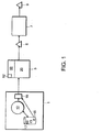
図1はラピッド・プロトタイピング用の特定の装置の概略図である。図には、コンピュータ1、3次元プリンタ3、形成された3Dプリンタ物体5、後処理システム7、および後処理された、最終造形物となる3D模型物体9が示されている。
FIG. 1 is a schematic diagram of a specific apparatus for rapid prototyping. In the figure, a
コンピュータ1は、デスクトップ・コンピュータまたはポータブル・コンピュータなどのパーソナル・コンピュータであってもよい。コンピュータ1は、インターネットのような公衆アクセス通信ネットワークを含む、スタンドアロン・コンピュータ、LAN(ローカルエリア・ネットワーク)の一部またはWAN(ワイドエリア・ネットワーク)であってもよい。本発明によれば、コンピュータ1はCAD(コンピュータ支援設計)/CAM(コンピュータ支援製造)プログラムのようなソフトウェア・アプリケーション12を含む。CAD/CAMプログラム12は、データ格納領域15に格納された3次元物体のディジタル表現を操作する。CAD/CAMプログラム12は、格納されたディジタル表現17を生成、修正および再生できる。ユーザが格納された物体表現17の模型物体9を製作することを望む場合、ユーザは格納された物体表現を高レベルのソフトウェア・プログラム18にエクスポートする。次に、高レベル・プログラム18から、ユーザはプログラム18にプリント命令を出す。プログラム18はディジタル表現17を、それぞれが所定の厚さを有する複数の個別の2次元層に分割する。
The
プログラム18は、高レベル命令を送ってプリンタ3の(3次元プリンタを作動する)電子回路52を制御することにより、各層をプリントする。これとは別に、物体17のディジタル表現は、プリンタ・ハードウェアにより、コンピュータ読出し可能な媒体(例えば、磁気または光ディスク)から直接読み出しできる。3次元プリンタ3は、プリントが実行されるダーティ(dirty)領域20と、制御電子回路52が収納されるクリーン領域50とを含む。
The
3次元プリンタ3はインクジェット式プリントヘッドを使用して、粉末造形材料の連続層の上に結合剤を堆積させる。これについては、Bredtらに対する米国特許No.5,902,441に記載されており、この全文は参照により本明細書に引用したものとする。結合剤が造形粉末と結合すると、粉末は反応を起こし、硬化して固体構造体になる。これらのプリントヘッドからの結合剤の小液滴の(滴下)位置を制御することにより、固体構造体の2D断面を物理的に再現できる。3次元プリンタ3は、プログラム18により提供される分割された各層毎に物理層を形成する。ディジタル表現17を複数の2次元層に分割したデータを含むファイルが完全にプリントされると、3次元造形物5が形成される。粉末を結合させて物体を形成することに関する詳細は、Sachsらに対する米国特許No.5,340,656、Cimaらに対する米国特許No.5,387,380、およびBredtらによる(代理人事務処理No.2247.2001−001)2001年4月13日に出願の米国特許出願No.09/835 292の発明「固体物体の3次元プリントの組成物」に開示されており、前記3者の全文は参照により本明細書に引用したものとする。
The three-
後処理システム7を使用して、プリントされた造形物となる部分5を最終造形物となる模型物体9に改良する。所望の結果に応じてさまざまな仕上げオプション(加工)が利用できる。
The
当業者には、3次元物体の模型製作に用いられる方法は、コンピュータ使用可能な媒体を含むコンピュータ・プログラム・プロダクトで実現できることは認識されるであろう。例えば、このようなコンピュータ使用可能な媒体は、ソリッド・ステート・メモリ・デバイス、ハード・ドライブ・デバイス、CD−ROM、DVD−ROM、またはコンピュータ・ディスケットなどの読出し可能メモリ・デバイスを含み、これらのメモリ・デバイス上には、コンピュータ読出し可能なプログラム・コード化した複数のセグメントが格納される。コンピュータ読出し可能な媒体はまた、光学的、有線または無線によるバスまたは通信リンクのような通信または伝送媒体を含むことができ、通信または伝送媒体は、ディジタルまたはアナログ・データ信号として保持されるプログラム・コード化したセグメントを有する。 Those skilled in the art will recognize that the method used to model a three-dimensional object can be implemented in a computer program product that includes a computer usable medium. For example, such computer usable media include readable memory devices such as solid state memory devices, hard drive devices, CD-ROMs, DVD-ROMs, or computer diskettes, and these On the memory device, a plurality of computer-readable program coded segments are stored. The computer-readable medium can also include a communication or transmission medium such as an optical, wired or wireless bus or communication link, which is a program program held as a digital or analog data signal. Has coded segments.
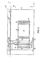
図2は、図1の3次元プリンタ3の実施形態の平面図である。前部の粉末の多いダーティ領域20および後部のクリーン領域50が詳細に示されている。チャンバ24、26、28の3つの開口に加えて、上部デッキ22は以下に述べる研削セクション29を含む。プリント・ガントリ49は、トラック57および支持棒23に連結されたアーム・アセンブリ55により上部デッキ22の上方で吊られている。作動中は、アームはトラック57および支持棒23上をx軸(低速軸)に沿って移動し、ガントリ40を移動させる。
FIG. 2 is a plan view of an embodiment of the three-
図示するように、ガントリ40は結合剤溶液を堆積させるプリントヘッド45を保持する。プリントヘッド45はプリント・トラック46に沿ってy軸方向に往復運動する。1つの実施形態では、ガントリ40は、結合剤溶液を堆積するための複数の結合剤ジェット47を有する少なくとも1つのインクジェット・プリントヘッド45を含む。結合剤ジェットは結合剤コンジット77から結合剤溶液を受け取る。また、図には、材料供給チャンバ24から造形チャンバ26に造形粉末を拡散するスプレッダローラー48が示されている。
As shown, the
空気流れ
装置内部で空気を循環させることにより、さまざまな問題を解決できる。1つの特定の問題は空中浮遊している粉末、つまり飛散した粉末であり、これによりプリンタ機構および電子構成部品が汚染され、結果的に装置の信頼性が低下する。また、粉末は装置の上蓋内部に堆積し、結果的に装置動作を監視するオペレータ能力を低下させる。
Air flow Various problems can be solved by circulating air inside the device. One particular problem is airborne powder, i.e., scattered powder, which contaminates the printer mechanism and electronic components, resulting in reduced device reliability. Also, the powder accumulates inside the top lid of the device, resulting in a reduced operator ability to monitor device operation.
図3Aは、図1の3次元プリンタの実施形態を通る空気流れを調整するための基本構成部品の斜視図である。図のように、3次元プリンタ3は複数の開口を有する上部デッキ22を含む。上部デッキ22は構造フレームに取り付けられている。供給ピストン25を有する矩形の材料供給チャンバ24、造形テーブル27を形成する造形ピストンを有する矩形の造形チャンバ26、およびオーバーフロー・シュート28が、x軸(低速軸)に沿って示されている。簡単化のために図では省略しているが、ピストン25、27がチャンバ24、26の壁面に対し滑らかに動くように、シールを固定している。また図示していないが、上蓋はプリント領域を外部環境から隔離している。
FIG. 3A is a perspective view of the basic components for regulating the air flow through the embodiment of the three-dimensional printer of FIG. As shown, the three-
図3Aはまた、使用済み造形材料を回収するように設計されたプリンタの構成部品を示す。このプリンタでは、オーバーフロー・シュート28に流れ込む造形材料は、収集バケットト81内に収集される。収集バケット81はプリンタの底面上の取付け台82にスライド挿入されるので、バケット81はシュート28の底から出る造形材料を収容するように位置される。上部プレート83はバケット81上にシールを形成し、上部プレート83上に取り付けられたブロワー34はシュート28を通る下方への通風を発生させる。フィルタ31は上部プレート83上で、ブロワー34とバケット81および上部プレート83により囲まれたキャビティとの間に取り付けられる。これら構成部品の位置的構成により、オーバーフローした造形材料は、フィルタ31ではなく、主としてバケット81内に収集される。
FIG. 3A also shows the components of a printer designed to collect used build material. In this printer, the modeling material flowing into the
バケット81の底に落ちる造形材料は、シュート28からブロワー34を通過する空気の流路から除去される。バケット81は容易に取り外しできるので、図3Bに示すように、造形材料を材料供給チャンバに戻すことができる。バケット81のリップ84は造形材料をチャンバに戻すのを容易にする。
The modeling material falling to the bottom of the
1つの実施形態では、1つまたは複数の光センサを配置しているので、バケットが一杯になったことを検知できる。例えば、光センサは、シュート28の終端部の内側の位置で検知するように配置される。“フル(full)”表示がなされると、バケット81は取り外され、造形材料は、汚染物または凝集した材料を除去するスクリーンを通して材料供給チャンバに戻される。
In one embodiment, one or more photosensors are arranged so that it can be detected that the bucket is full. For example, the optical sensor is arranged to detect at a position inside the terminal portion of the
余分な粉末を捕集することに加えて、オーバーフロー・シュート28を通る空気流れは飛散粉末の量を低減するので、装置の信頼性およびユーザ満足度を向上させる。
In addition to collecting excess powder, the air flow through the
別の実施形態では、コンジットを介して、真空ポンプを材料供給チャンバ24および/または造形チャンバ26に連結できる。材料供給チャンバが一杯のときに、空気を造形材料から材料供給チャンバ24の底面を通して吸引することにより、造形材料を材料供給チャンバ内に高密度で均一に詰め込むことができる。これにより、飛散粉末の望ましくないかたまり(cloud)を発生させる傾向がある、時間のかかる工程である充填の間にオペレータがこてを用いて造形材料から空気を出す作業の必要性が減少する。
In another embodiment, a vacuum pump can be coupled to the
また、空気を造形材料から造形チャンバ26の底面または側面を通して吸引することにより、造形材料を造形チャンバ内により高密度で詰め込むことができる。この高密度の材料により、造形チャンバ内で形成される造形物を確実に支持できる。これにより、造形工程の間に造形物が動くのを防止し、形成される造形物の品質を向上させる。
Also, by drawing air from the modeling material through the bottom surface or side surface of the
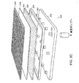
図3Cは、材料供給チャンバ24および造形チャンバ26の底面上に置くことができるプレナム240の1つの実施形態を示す。プレナム240はプレナムの基台として働くピストン・プレート242を含む。真空ポンプは開口244を通して取り付けられる。
FIG. 3C shows one embodiment of a
ピストン・プレート242の上には、フィルタ媒体248を支持し、かつ貫通した孔250が設けられている上部プレート246が位置する。フィルタ媒体248は、造形材料と真空システムとを離間させており、また別のインライン(一列に並んだ)・フィルタを含むことができる。孔250は、下方への空気流れの通路を提供し、最適空気流れ特性となるように配置できる。
Located on the
さらに、複数のスペーサ252をピストン・プレート242と上部プレート246の間に設けて、プレナム240内の均一な真空分布を保証する。さらに、ピストン・プレート242と上部プレート246の間のガスケット254がプレナム240の縁部からの空気漏れを防止する。フィルタ248の上にメッシュ256を置き、セットアップおよび清浄化作業の間、フィルタ248を保護する。プレナム240は、メッシュ256からピストン・プレート242に延びる外周部に沿ってねじを用いてサンドイッチ状に一体にしてはさまれる。プレナム240の外周部にシールを設けて、ピストンとチャンバ壁の間の粉末損失を防止する
In addition, a plurality of
図3Dは、材料供給チャンバ24および/または造形チャンバ26を通る空気流れの制御を示す概略図である。図のように、真空ポンプ258は、材料供給チャンバ・プレナム241および造形チャンバ・プレナム243に連結されて、それらプレナムの一方または両方を通る空気流れを発生させる。1つの実施形態では、真空ポンプ258は1.5〜2in3(2.5〜3.3×10−5m3)/分の空気流れ量で水銀柱約10インチ(254mm)の真空レベルを可能にする。図では、真空ポンプ258、材料供給チャンバ・プレナム241および造形チャンバ・プレナム243間に第1バルブ260が置かれている。第1バルブ260により、材料供給チャンバ・プレナムまたは造形チャンバ・プレナムのどちらかを通るように、空気流れの方向を選択できる。特に、スイッチ262はユーザが操作できるように構成され、例えば、ユーザが材料供給チャンバ24を充填するときは、スイッチ262でバルブ260を操作して、全空気流れを材料供給チャンバ・プレナム241を通るように方向付けする。材料供給チャンバ24を充填後、ユーザは、フット・ペダルであるスイッチ262を操作して、全空気流れが造形チャンバ・プレナム243を通るように方向付けできる。バルブ260および/または真空ポンプ258の間に流量計261を置いて、このバルブ260と真空ポンプの間の空気容積流量を測定する。
FIG. 3D is a schematic diagram illustrating the control of air flow through
さらに、バルブ260と造形チャンバ・プレナム243の間に、3方向バルブであるバルブ264を置くことができる。バルブ264はソフトウェア命令265に接続され、制御される。詳細には、製作工程の間、ソフトウェア命令265は、電力線268間に接点を形成するソリッド・ステート・リレー266を制御することにより、バルブ264を制御して、選択的に空気流れが造形チャンバ・プレナム243を通るようにできる。例えば、造形材料を供給する間は、空気流れを造形チャンバ・プレナム243に流し、結合剤溶液をプリントする間は、空気流れを止めることができる。材料供給チャンバ・プレナムおよび/または造形チャンバ・プレナムの近くに複数のインライン・ゲージ270を取り付けて、それらの位置の真空レベルを測定できる。さらにインライン・フィルタを設けて、プレナム241および243の周囲またはそれらを通過する造形材料または残留物を濾過する。1つの実施形態では、造形チャンバ・プレナム243とバルブ264の間に調整可能なレギュレータ274を設けて、造形チャンバ・プレナム243を通る空気流れを調整する。さらにゲージ276をレギュレータ274に接続して、このレギュレータの真空レベルを測定する。
Further, a
プリント
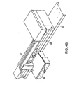
図4Aは、単色および多色モードの両方で高速プリントするのに特に適している高速プリント3次元プリンタの構成部品を示す。キャリッジ85が往復運動するようにガントリ40に取り付けられている。キャリッジ85は、レール86上でy軸(高速軸)に沿って往復運動できる。図4Bには、上蓋を閉じた状態のキャリッジ85、およびガントリ40が、結合剤コンジット87と共に示されている。図4Cは上蓋を開いたキャリッジ85を示している。
Printing FIG. 4A shows the components of a high speed printing 3D printer that is particularly suitable for high speed printing in both single color and multicolor modes. The
4つのほぼ同一のプリントヘッド45(Hewlett Packard部品番号C4800A等)がキャリッジ85内に取り付けられている。各プリントヘッド45はコンジット87の1つに接続されており、これらのコンジットは外部結合剤溶液供給源に接続されている。1つの実施形態では、第1のプリントヘッドがシアン着色剤を含む結合剤溶液を供給する供給源に接続され、第2のプリントヘッドがマゼンタ着色剤を含む結合剤溶液を供給する供給源に接続され、第3のプリントヘッドがイエロー着色剤を含む結合剤溶液を供給する供給源に接続され、さらに第4のプリントヘッドが透明(またはホワイト)着色剤を含む結合剤溶液を供給する供給源に接続されている。ブラック着色剤を含む結合剤を供給する供給源に接続され、かつ他のプリントヘッドとはx軸に沿ってずれている第5のプリントヘッドをキャリッジ85内に設けることができる。種々の着色剤を結合剤溶液と予め混合しそれぞれの供給源に貯蔵できる。または、種々の着色剤を別個に貯蔵し、装置内で、例えばプリント前にプリントヘッドにおいて結合剤溶液と混合することもできる。
Four substantially identical print heads 45 (such as Hewlett Packard part number C4800A) are mounted in the
図5A−5Dは造形粉末を処理する工程を示す概略図である。上部デッキ22に頂部を揃える形で、材料供給チャンバ24、造形チャンバ26、およびオーバーフロー・シュート28が示されている。造形粉末60の供給は、材料供給チャンバ24の可動供給ピストンによりなされ、また造形テーブル27は造形チャンバ26内に示されている。当技術分野では公知のように、作動中、供給ピストン25は徐々に上方向(z+方向)に移動し、一方で、造形テーブル27は徐々に下方向(z−方向)に移動する。オーバーフロー・シュート28を通り下方に流れる空気流れは、ブロワー34(図3A)により発生する。
5A-5D are schematic diagrams illustrating a process of processing a modeling powder. A
図5Aを参照すると、材料供給リザーバ・チャンバ24の底面25は、1つの造形層に対して十分な量62の造形材料60を材料供給チャンバ24から上に押し出すように位置している。造形テーブル27は、造形材料の第1層を受け入れるだけの特定の深さに位置している。1つの実施形態では、造形テーブル27は徐々に下降し、それぞれが約3〜9ミル(約76〜230ミクロン)厚さの連続する複数の造形層を生成する。
Referring to FIG. 5A, the
図5Bを参照すると、ローラーは、その前進方向と逆に回転して、一定量の造形材料62を造形チャンバ26方向に押し出している。図5Cに示すように、ローラー48は造形チャンバ26を横断して移動し、一定量の造形材料64の層を造形テービル27上に堆積させる。完全な造形層を造形テーブル27上に確実に堆積させるために、材料供給リザーバ24により造形材料60を余分に供給する。余分な造形材料66はローラー48によりオーバーフロー・シュート28内に排出される。排出された材料粒子は重力および空気流れにより収集バケット81(図3A)に運ばれる。
Referring to FIG. 5B, the roller rotates in the opposite direction to the forward direction to push a certain amount of the
再度図2を参照すると、ガントリ40が上部デッキ22の上方を通過するとき、ガントリ表面で飛散粉末が飛散結合剤材料と混合する結果として、通常、硬い表面を持つ層がガントリの底面上に形成される。この層は時間と共に厚くなって、粉末ベッドにとって障害となり、その結果、粉末ベッドの上層に凹部または溝を発生させ、最終仕上げされた造形物となる最終部分に割れ目を発生させる。小型ブラシ、ループ材料(例えば、Velcro(R)ファスナ材料)、または別の研削材29を上部デッキ22上に配置して、ガントリの底面から余分な残留物を掻き落とすことができる。この残留物はオーバーフロー・シュート28に落とすことができる。
Referring again to FIG. 2, when the
ガントリのx方向への移動により1つの層を堆積させると、その層の2D断面がプリントされる。詳細には、このプリントは、ガントリを負のx軸方向に移動させながら、プリントヘッドを連続的にy軸方向に移動させる間においてなされる。この代わりに、以下に詳細を述べる別のプリント方法を使用することもできる。 When a layer is deposited by movement of the gantry in the x direction, a 2D cross section of the layer is printed. Specifically, this printing is performed while moving the print head continuously in the y-axis direction while moving the gantry in the negative x-axis direction. Alternatively, another printing method, detailed below, can be used.
造形材料が広がると共に、粉末65の起伏ができ、ローラーの運動方向に対して横方向に移動する傾向がある。押え片(プラウ(plow))49は粉末65の起伏を抑えるのに役立つ。これにより、造形材料が上部デッキ22上に溢れ出すのを防止し、さらに装置の信頼性およびユーザ満足度の点で望ましくない隆起部を形成するのを防止する。押え片49は、回転および平行移動するスプレッダローラー48の端部と、上部デッキ22の上面とに対するシールを形成する。スプリングを利用して、押え片49に対して両方向から内側向きの力を発生させることにより、押え片49がスプレッダローラー48との緊密なシールを形成するようにできる。スプリングはまた、押え片49に下方向の力を発生させて、上部デッキ22の上面とのシールを形成する。
As the modeling material spreads, the
押え片49を油含浸プラスチック材料から製作しているので、粉末を拡散させている間の、押え片49の底面と上部デッキ22の上面との間の摩擦を低減できる。油含浸材料はまた、粉末が押え片49の底面に付着するのを防止する隔壁を形成する。さらに、油含浸材料は上部デッキ22の支持表面上に自己補充剥離層(self-replenishing release layer)を形成できる。
Since the
スプレッダローラー48が粉末65の起伏を押し付けるとき、ローラーの前端部には、押え片49の前面領域上に押し付けられた粉末の堆積部分が生じる。この粉末は押え片49により押され、最後にオーバシュート28内に引き込まれて落下するか、またはその進路方向から外れて堆積される。オーバーフロー・シュート28は材料供給リザーバ24および造形チャンバ26の開口より幅を広くして、この余分粉末を捕集できる。
When the
プリントの間に、粉末層に衝突する結合剤の衝撃により、粉末が飛散して、プリントヘッドの底面に衝突する。プリントヘッドは結合剤溶液で濡れているため、粉末は硬化して、プリントヘッドの底面上に硬い表層を形成するか、または最終的に粉末がジェットの内部に入り込み、ジェットの出口を詰まらせる可能性がある。さらに、時には、余分な結合剤が液滴を形成することがあり、この液滴はプリントヘッドの底面に残り、表面張力によりそこに留まる。この影響によっても、ジェットの出口が詰まるか、またはジェットの偏向が生じることがある。ジェットが詰まるかまたはずれると、結合剤が所望の位置に付着しないため、最終仕上げされた造形物に不具合が発生する。したがって、プリントヘッドの底面から粉末または結合剤を除去して、ジェット出口が開いた状態(つまり、クリーンな状態)に維持するための方法が望まれる。 During printing, due to the impact of the binder that collides with the powder layer, the powder scatters and collides with the bottom surface of the print head. Because the printhead is wet with the binder solution, the powder can harden and form a hard surface on the bottom of the printhead, or eventually the powder can get inside the jet and clog the jet outlet There is sex. In addition, sometimes excess binder can form droplets that remain on the bottom of the printhead and remain there due to surface tension. This effect may also clog the jet outlet or cause jet deflection. When the jet is clogged or displaced, the binder does not adhere to the desired position, causing a defect in the final finished shaped object. Therefore, a method for removing the powder or binder from the bottom surface of the printhead and maintaining the jet outlet open (ie, clean) is desired.
図4Aに示すように、上部デッキ22には凹部90が形成されている。この凹部には、プリント・ジェットを清浄化するための、構造フレームおよび上部デッキ22に対して移動可能な少なくとも1つのスキージ(squeegee)またはワイパー部材を含む。この凹部90は、スキージがプリント・ジェットの移動軌道内にある限り、上部デッキのどの位置にでも形成できる。図4Aの実施形態では、凹部90はオーバーフロー・シュート28から離れた、造形材料供給リザーバ24および造形チャンバ26の反対側に形成される。さらに図4Dおよび4Eに示すように、凹部90内に取り付けられたクリーニング・アセンブリ200は、モータ206により上下運動する支持部材204上に取り付けられたスキージ209を含む。詳細には、モータ206は、ギヤ210と噛合って駆動するギヤ208を回転させる。ギヤ208、210はシャフト212(図4Eではシャフトを1つだけ示す)に連結され、このシャフトを回転させる。このシャフト212はカム214を回転させて、支持部材204に取り付けられた中間部材216を上下動させる。PCボート220はセンサ222を保持し、このセンサは、シャフト212の1つに取り付けられたホイール224の位置を検出することにより、スキージの位置(上方または下方)を検出する。ホイール224は、センサ222で検出してスキージが上方または下方のどちらに位置しているかを決定するための埋め込み磁石を含む。クリーニング・アセンブリ200は、そのアセンブリを凹部90内に固定するためのフランジ218を含む。
As shown in FIG. 4A, a
作動中は、ガントリ40がオーバーフロー・シュート28を通過して、凹部90に向かって移動するとき、モータ206が支持部材204を上方に持上げることにより、スキージ209がデッキ22の上に突出して、プリントヘッド面をこすり、清浄化する。その後、スキージ209は凹部90内に収納される。
In operation, when the
別の実施形態では、クリーニング・スキージは、上部デッキ22の上のような適所に固定できる。この時、クリーニング・スキージは、プリントヘッがスキージ上を定期的に通過、例えば、プリント毎に通過するように配置することができる。この時、堆積した粉末および結合剤は、スキージによりプリントヘッドから掻き落とすことができる。この後、スキージは、例えば近接して配置されたクリーニング・ジェットまたはプリントヘッド・ジェット自体からのクリーニング剤により清浄化される。適正な排出手段をプリンタ内に組み込んで、廃棄材料を排出できる。固定されたスキージは機械的な複雑性が少ないが、すべての実施形態に適合するとは限らない。
In another embodiment, the cleaning squeegee can be secured in place, such as on the
複雑性は増すが、収納式スキージの利点は、スキージを使用しないときには、凹部90内で保護されることである。また、スキージ209がデッキ22の下方に位置するか、または下方に移動するとき、クリーニング剤、例えば透明結合剤を含む1つまたは複数のノズル226をスキージに向けて噴射し、清浄化する。ノズル226をデッキ22の下方に位置させることで、クリーニング剤の噴射は大概、凹部90内で行われる。
While increasing in complexity, the advantage of the retractable squeegee is that it is protected in the
別の実施形態では、クリーニング剤は潤滑特性を有する液体を含む。すなわち、クリーニング剤はスキージ209上に膜を形成し、この膜がプリント・ジェットに移動するので、造形材料がプリント・ジェットに付着しにくくなる。特定の実施形態では、クリーニング剤は約5〜20%のポリエチレン・グリコールを混合した水である。
In another embodiment, the cleaning agent comprises a liquid having lubricating properties. That is, the cleaning agent forms a film on the
支持部材204はプリントヘッド・キャップ・アセンブリ202を有し、これらのアセンブリにより、使用されていないときのプリントヘッドを保護する。
プリント速度および造形品質
造形速度を最大化することは、ユーザの重要な関心事項である。造形時間は2つの主要な要素、すなわち粉末の拡散と結合剤溶液の堆積とを有する。粉末の拡散速度はいくつかの要因で制限される。これら要因には、平滑な表面層の維持および飛散粉末量の最小化を必要とすることが挙げられる。したがって、造形速度を増加させる1つの方法は、結合剤の堆積速度を増加させることである。結合剤の堆積速度を増加させる1つの方法は、複数のプリントヘッドを利用することである。
Printing speed and build quality Maximizing build speed is an important user concern. Build time has two main components: powder diffusion and binder solution deposition. The powder diffusion rate is limited by several factors. These factors include the need to maintain a smooth surface layer and minimize the amount of scattered powder. Thus, one way to increase the build speed is to increase the deposition rate of the binder. One way to increase the deposition rate of the binder is to utilize multiple printheads.
図6は複数のプリントヘッドを使用する装置の概略図である。この構成はモノクロ・プリント・モードにおけるプリント速度を最大にする。なぜなら、全プリントヘッド45が同時にプリントすることにより、各ジェットアレイの幅Wjにプリントヘッド数を乗じた幅に等しいx方向の全幅Wtを完全にカバーできるからである。y方向全体にわたりこの全幅Wtをプリント後、ガントリは全幅Wtに等しい距離だけx方向に進行する。次に、プリントヘッド45は再度、y方向全体にわたり全幅Wtをカバーしてプリントする。
FIG. 6 is a schematic view of an apparatus using a plurality of print heads. This configuration maximizes printing speed in monochrome print mode. This is because all the print heads 45 can simultaneously cover the entire width Wt in the x direction equal to the width obtained by multiplying the width Wj of each jet array by the number of print heads. After printing this full width Wt over the entire y direction, the gantry advances in the x direction by a distance equal to the full width Wt. Next, the
この構成はまた、カラー・プリントに対しても有効である。図6に示す特定の実施形態では、4つのプリントヘッドがあり、3つのプリントヘッドのそれぞれは原色をプリントし、1つは透明色をプリントする。カラー・プリントの場合、ガントリは1つのジェットアレイWjの幅だけ進行し、それにより、固有の色を有するプリントヘッドはそれぞれ粉末の各領域の上を通過することになる。 This configuration is also effective for color printing. In the particular embodiment shown in FIG. 6, there are four printheads, each of which prints a primary color and one prints a transparent color. For color printing, the gantry advances by the width of one jet array Wj, so that each printhead with a unique color will pass over each area of the powder.
プリントヘッド45を一列に隣接させて配置しない理由は、各プリントヘッドWpの幅がジェットアレイの幅Wjより大きいために、一列に隣接させて配置すると、プリントされていない縦のストライプ(縞模様)が発生するからである。したがって、すべての領域をプリント可能にするために、プリントヘッド45をy軸方向にオフセット距離Wyずつ互いにずらせて配置して、プリントヘッド45の物理的制約に対処している。 The reason why the print heads 45 are not arranged adjacent to each other is that the width of each print head Wp is larger than the width Wj of the jet array. This is because. Therefore, in order to make it possible to print all the areas, the print heads 45 are offset from each other by an offset distance Wy in the y-axis direction to deal with physical restrictions of the print heads 45.
プリントヘッド45はまた、x軸に沿ってオフセット距離Wxずつ互いにずれている。実際には、プリントヘッド45は、x軸においてプリント範囲がわずかに重なる部分Woが存在するように整列されている。すなわち、隣接する2つのプリントヘッド45が同一のx軸の位置上で同時にプリントできる。これにより、装置の組立て後にプリントヘッド45を校正できるため、設計および製造工程における精度を落とすことができる。この時、重なり合うプリントヘッド45の一方は、他方のプリントヘッドのピクセルと重なるいくつかのピクセルをプリントしないように命令される。
The print heads 45 are also offset from each other by an offset distance Wx along the x-axis. In practice, the print heads 45 are aligned such that there is a portion Wo where the print range slightly overlaps in the x-axis. That is, two adjacent print heads 45 can simultaneously print on the same x-axis position. Thereby, since the
図6には、クリーニング・エレメント209が示されている。クリーニング・エレメントはy軸に沿って間隔を空けて整列しているので、各クリーニング部材は対応するプリントヘッドに位置合わせされている。
In FIG. 6, a
他のプリントヘッド構成を使用できることは認識されるべきである。他の典型的な実施形態の詳細な説明は、引用した米国出願No.09/416,787に開示されている。構成の選択は、プリントヘッド仕様を含むさまざまなパラメータを考慮に入れる設計事項である。 It should be appreciated that other printhead configurations can be used. A detailed description of other exemplary embodiments can be found in the cited US application no. 09 / 416,787. The choice of configuration is a design consideration that takes into account various parameters including printhead specifications.
例えば、プリントヘッド45を高速のy軸に沿って一列に配列させて、結合剤ジェットの連続シーケンスを形成できる。この配列により、結合剤を堆積させる間、プリントヘッド45は高速のy軸に沿って移動または往復運動する必要がなくなる。
For example, the print heads 45 can be arranged in a line along the fast y-axis to form a continuous sequence of binder jets. This arrangement eliminates the need for the
この配列の変形例には、高速y軸に沿ったプリントヘッドの部分列を含むことができる。つまり、複数のプリントヘッドのうち一部を一列に整列させる。プリントヘッドが低速のx軸に沿って(x+方向に)通過する間に、最初に結合剤の堆積が発生する。この通過が完了すると、プリントヘッドを高速y軸に沿って割り送りして、結合剤を戻り(x−方向)の通過時に堆積する。この工程を繰り返して、全プリント範囲をカバーする。 Variations on this arrangement can include a printhead subsequence along the fast y-axis. That is, some of the plurality of print heads are aligned in a line. While the printhead passes along the slow x-axis (in the x + direction), binder deposition first occurs. When this pass is complete, the printhead is indexed along the fast y-axis, and the binder is deposited on the return (x-direction) pass. This process is repeated to cover the entire print range.
また、特定のジェットの動作に問題がある場合にも、場所的に均一高強度を持つ造形物を得ることが望まれる。例えば、プリントヘッドの製造品質が劣っているかまたはヘッドが粉末により汚染された結果、場合により、プリントヘッドの特定のジェットが噴射しないか、または噴射が不安定になることがある。 Even when there is a problem with the operation of a specific jet, it is desirable to obtain a shaped article having a uniform high strength in place. For example, printhead manufacturing quality may be poor or the head may be contaminated with powder, resulting in certain printhead jets not firing or unstable jetting.
図7は、不完全な結合剤ジェットを有するプリントヘッドの概略図である。図に示すように、プリントヘッド45fは、ガントリ40(図2)が移動するとともに、y軸に沿ってプリントする複数のプリントヘッドのうちの1つである。プリントヘッド45fの特定のジェット47−6が噴射しない場合、プリントされている粉末の特定の層64上にy方向においてストライプ96が表われることがある。これによりプリントされた領域95に望ましくない不連続性が生じる。問題は、結合されていない粉末96の縦のストライプが各層において同一のx軸上の位置xfに存在するため、いったん造形物が完成すると、デラミネーション(積層剥離)の面が発生することである。
FIG. 7 is a schematic view of a printhead having an incomplete binder jet. As shown in the figure, the
図8は不完全な結合剤ジェットを用いて2つの層をプリントする方法を示す概略図である。本発明によれば、シングリング(shingling)法を使用して、結合されていない縦のストライプ96−1、96−2を各層64−1、64−2上の異なるx軸上の位置に配置することにより、強度の弱い領域を1つの面に集中させずに造形物全体にわたり分散させる。したがって、不完全なジェット47−6は、すべての隣接する層に対し、通過する度にx軸上の異なる位置に配置される。複数カートリッジ・システムでのシングリングは、結合剤の新しい各層を堆積する前に、x軸に沿ってカートリッジ45をオフセットx0ずつわずかにずらすことにより達成される。
FIG. 8 is a schematic diagram illustrating a method of printing two layers using an incomplete binder jet. According to the present invention, unjoined vertical stripes 96-1, 96-2 are placed at different x-axis locations on each layer 64-1, 64-2, using a shingling technique. By doing so, the area | region with weak intensity | strength is distributed over the whole molded article, without concentrating on one surface. Thus, the imperfect jet 47-6 is placed at a different position on the x-axis each time it passes for all adjacent layers. Shingling at multiple cartridge system prior to depositing the new layer of binder, it is accomplished by shifting the
高速の造形速度を維持する一方で、造形部分の強度を最適化することが望ましい。単位面積当たりにより多くの結合剤を堆積することにより、部分の強度を強化できる。しかし、多量の結合剤の堆積は、造形速度を低下させて、部分のひずみを発生させる欠点がある。部分の強度を向上させ、かつ造形速度を大幅に低減することなく部分のひずみを最少化する1つの方法は、各層の外周部に供給する結合剤の量を増加することにより、その外周部まわりに硬質の外殻を形成する方法である。これは、外周部に結合剤を供給するときに、造形物の外周部に2倍の結合剤を供給して、結合剤流量を増加するか、または結合剤の飽和を調整することにより達成される。この方法はさらに、造形物の内部領域のひずみを制御できる利点を持つ。 It is desirable to optimize the strength of the modeling part while maintaining a high modeling speed. By depositing more binder per unit area, the strength of the part can be enhanced. However, the deposition of a large amount of binder has a drawback in that the forming speed is lowered and a distortion of a part is generated. One way to improve the strength of the part and minimize the distortion of the part without significantly reducing the build speed is to increase the amount of binder supplied to the outer perimeter of each layer, around the perimeter This is a method of forming a hard outer shell. This is achieved by supplying twice the binder to the outer periphery of the shaped object, increasing the binder flow rate or adjusting the saturation of the binder when supplying the binder to the outer periphery. The This method has the further advantage of being able to control the strain in the internal region of the shaped object.
造形モデルの特性を最適化するために、単位面積当たりに供給する結合剤の量を調整して、使用する特定の粉末タイプおよびそのモデルの幾何形状の両方に適合させる。公称では(飽和度=1)、プリントヘッドは、固体領域をプリントするときに、結合剤溶液量をこの領域の約10〜20%に供給する。ピクセルの一部をプリントしないことにより、同一面積走査速度を維持しながら、単位面積当たりの結合剤量をこのレベルより少なく(飽和度<1)できる。単位面積当たりの公称結合剤量より多い量(飽和度>1)でプリントするには、プリントヘッドからの同一流量を維持しながら、面積走査速度を減少させる。これは、ビットマップ・イメージを高速走査方向に拡大し、同時に高速軸モータを比例して減速することにより達成できる。1.5の飽和度を得るには、例えば、180×180ピクセル領域を180×270ピクセルに拡大し、高速軸速度を90cm/secから60cm/secに減速する。このような可変飽和度法により、造形物の強度を最適化できる。 In order to optimize the characteristics of the shaped model, the amount of binder delivered per unit area is adjusted to suit both the particular powder type used and the geometry of the model. Nominally (saturation = 1), the printhead supplies an amount of binder solution to about 10-20% of this area when printing a solid area. By not printing some of the pixels, the amount of binder per unit area can be less than this level (saturation <1) while maintaining the same area scan speed. To print with an amount greater than the nominal binder amount per unit area (saturation> 1), the area scan speed is reduced while maintaining the same flow rate from the print head. This can be accomplished by enlarging the bitmap image in the fast scan direction and simultaneously decelerating the fast axis motor proportionally. To obtain a degree of saturation of 1.5, for example, the 180 × 180 pixel area is enlarged to 180 × 270 pixels and the high speed axial velocity is reduced from 90 cm / sec to 60 cm / sec. By such a variable saturation method, the strength of the shaped object can be optimized.
例えば、造形物は、硬い外殻、およびその内部領域にトラス(truss)または卵ケース構造を有するように形成できる。内部領域の残りの部分は結合されない粉末のままで残すことができる。 For example, the shaped object can be formed to have a hard outer shell and a truss or egg case structure in its interior region. The remaining part of the inner region can be left unbound powder.
カラー・プリント
カラーのインク・ジェット・プリントヘッドをプリンタに組み込むことにより、様々なカラーまたはインクをプリントする能力を提供できる。システムはこれらのプリントヘッドを利用して液体結合剤を堆積させるため、これらプリントヘッドにより、多孔質材料を結合させる材料としてカラー結合剤を堆積できる。特に、粉末材料はホワイトまたは無色であり、インクを吸収して粉末に色を付けることができる。結果的に、本発明の実施形態は、実質的にフルカラーの3次元造形物を造形し、造形物全体にわたって色を変化させることができる。
Color printing Color ink-jet printheads can be incorporated into printers to provide the ability to print a variety of colors or inks. Because the system utilizes these printheads to deposit liquid binders, these printheads can deposit color binders as materials that bind porous materials. In particular, the powder material is white or colorless and can absorb ink and color the powder. As a result, the embodiment of the present invention can model a substantially full-color three-dimensional structure and change the color throughout the entire structure.
例えば、製品設計者は、表面に予め施されたさまざまな配色、ラベルおよび装飾を有する製品モデルを製作できる。さらに、外科医は患者の人体の一部の3Dカラー・プリントされたモデルを解体して、3次元配置の臓器、腫瘍、血管などを十分認識することにより手術の準備ができる。モデルに関するデータは、コンピュータ断層撮影装置(CT)または磁気共鳴映像装置(MRI)から得られる。 For example, a product designer can produce a product model with various color schemes, labels and decorations pre-applied to the surface. In addition, the surgeon can prepare for surgery by disassembling a 3D color printed model of a portion of the patient's human body and fully recognizing organs, tumors, blood vessels, etc. in a three-dimensional arrangement. Data about the model is obtained from a computed tomography apparatus (CT) or a magnetic resonance imaging apparatus (MRI).
色の付いた内部領域を必要とする造形物もあるが、表面色だけを必要とする造形物もある。目に見える表面が色付けを必要とする、造形物の一部であるため、ソフトウェアは各層の外側縁部のみに使用するカラー・インクを調整すればよい。このような場合、無色(すなわち、透明またはホワイト)あるいは単色結合剤(すなわち、ホワイト以外の単一色)が、ユーザには見えない造形物の内部に使用される。これにより、高価で、補充の面倒な着色結合剤を節減できる。 Some shaped objects require colored interior areas, while others require only surface color. Since the visible surface is part of the build that requires coloring, the software need only adjust the color inks used on the outer edges of each layer. In such cases, colorless (ie, clear or white) or monochromatic binder (ie, a single color other than white) is used inside the shaped object that is not visible to the user. This saves expensive and troublesome replenishing colored binders.
一定量の液体結合剤を所定量の粉末上に堆積して、正確に造形された造形物を製作できる。余分な結合剤は、造形物における所望の領域を越えて移行する結合剤を生じさせる。この作用は通常“ブリーディング(breeding)”と呼ばれる。しかし、この一定量より少ない量の結合剤では、強度の弱い造形物が製作される。色の量に関係なく十分な適正量の結合剤を使用することが望ましい。色の変化を制御した造形物を製作する方法は、以下に述べる。 Accurately shaped objects can be produced by depositing a certain amount of liquid binder on a predetermined amount of powder. Excess binder produces a binder that migrates beyond the desired area in the shaped object. This effect is usually referred to as “breeding”. However, if the amount of the binder is less than the predetermined amount, a molded article having a low strength is produced. It is desirable to use a sufficient appropriate amount of binder regardless of the amount of color. A method for producing a shaped object in which the change in color is controlled will be described below.
第1に、各層の縁部(これらの縁部は、最後には、造形物の表面になる)上でプリントするための最少飽和量を決定する。十分な着色剤を各着色結合剤に加えることにより、プリントするための最少飽和量で、仕上がった造形物の表面が純粋な原色になる。3原色のそれぞれで着色された結合剤をプリントする3つのプリントヘッドがある。透明結合剤をプリントする第4のプリントヘッドがある。 First, determine the minimum amount of saturation to print on the edges of each layer (these edges will eventually become the surface of the shaped object). By adding sufficient colorant to each colored binder, the surface of the finished shaped object becomes a pure primary color with a minimum amount of saturation for printing. There are three printheads that print binders colored in each of the three primary colors. There is a fourth printhead that prints the transparent binder.
各層をプリントする前に、コンピュータ・ソフトウェアは、最初に、所望の色を得るために、各プリントヘッドが各スポット内にプリントする必要のある着色結合剤の量を計算するアルゴリズムを実行する。次に、ソフトウェアは各スポットに対する最適飽和度(例えば、前述のように、内部にトラス構造を有する各層の外周部上の増加した飽和度)を決定するアルゴリズムを実行する。次にソフトウェアは、3色のプリントヘッド全てによりすでにプリントされた結合剤の総量を減算し、その後、第4プリントヘッドにより、透明な、したがって色に影響を与えない結合剤の残量を供給する。このように、各スポットは正しい量の各色と正しい量の結合剤とを供給される。 Prior to printing each layer, the computer software first executes an algorithm that calculates the amount of colored binder that each printhead needs to print in each spot to obtain the desired color. The software then executes an algorithm that determines the optimal saturation for each spot (eg, as described above, increased saturation on the outer perimeter of each layer having a truss structure therein). The software then subtracts the total amount of binder that has already been printed by all three color printheads, and then supplies the remaining amount of binder that is transparent and thus unaffected by color, by the fourth printhead. . Thus, each spot is supplied with the correct amount of each color and the correct amount of binder.
ディザリング(dithering)およびハーフトーン化したバックグラウンドを得るには、最初に、モノクロ・モードにおけるバックグラウンドについて理解することがすることが有効である。プリンタはホワイト粉末上にプリントし、2組のジェットアレイを有している。一方の組のジェットアレイはブラック結合剤を堆積し、他方の組のジェットアレイは、粉末がホワイトであるため、ホワイトで表われる透明結合剤を堆積する。造形される造形物各位置で、2種類の結合剤がある比率で堆積され、造形物のある領域で所望のグレー、ホワイトまたはブラックの陰影を生成する。このように、造形物の全ての領域は、強化の高い部分を生成するのに必要な総結合剤量を受け取る。ただし、この方法は、制御された大きさの液滴を生成できるプリントヘッドを必要とする。 To obtain dithering and halftoned background, it is useful to first understand the background in monochrome mode. The printer prints on white powder and has two sets of jet arrays. One set of jet arrays deposits a black binder, and the other set of jet arrays deposits a transparent binder that appears white because the powder is white. At each position of the modeled object to be modeled, two types of binders are deposited at a certain ratio to produce a desired gray, white or black shade in an area of the modeled object. In this way, all areas of the shaped object receive the total amount of binder necessary to produce a highly reinforced part. However, this method requires a printhead capable of producing controlled size droplets.
インク・ジェット・プリントヘッドを選択して、制御された大きさの範囲の液滴を生成できるが、最新のプリントヘッドは、1種類の大きさの液滴だけを生成するように使用される場合に最適動作する。したがって、液滴が層全体にわたり均一に分布する場合、造形物の断面の各位置に、ブラックの液滴または透明の液滴のどちらかが衝突する。ディザリングまたはハーフトーン化に対しては、これらの液滴を、十分に離れて見るときにはグレーに認識されるが、拡大したときにはドット・パターンに見えるように分布させることができる。 Ink jet printheads can be selected to produce droplets in a controlled size range, but modern printheads can be used to produce only one type of droplet Operates optimally. Therefore, if the droplets are uniformly distributed throughout the layer, either a black droplet or a transparent droplet collides with each position of the cross section of the shaped object. For dithering or halftoning, these drops are perceived as gray when viewed far enough away, but can be distributed to appear as a dot pattern when magnified.
ディザリングまたはハーフトーン化の従来の方法を各層に使用して、各結合剤の液滴を滴下する場所を決定できる。またアルゴリズムはディザリングまたはハーフトーン化方法に対しても機能して、仕上った造形物の表面に滴下する液滴の最適配置を決定する。 Conventional methods of dithering or halftoning can be used for each layer to determine where to drop each binder droplet. The algorithm also works for dithering or halftoning methods to determine the optimal placement of droplets to be dropped on the surface of the finished shaped object.
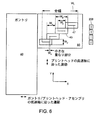
別の色の結合剤を堆積する別のノズルを追加することにより、前述の方法はフルカラーの造形物を製作できる。プリントされる物体の境界面に異なる色の表面が接する場合、アルゴリズムをプリントされる領域に適用して、各層の外周部にカラー・バンドを形成する(図9参照)。最も簡単なアルゴリズムは単純な半直角の面である。造形物は完全な不透明ではなく、したがって、造形物の観察者の認識する色は、色がプリントされる造形物の表面における濃度に依存する。したがって、広いカラー・バンド(color band)が細いカラー・バンドの色に比べて濃い色に見える。 By adding another nozzle that deposits another color binder, the method described above can produce a full color feature. When a surface of a different color touches the boundary surface of the object to be printed, an algorithm is applied to the printed area to form a color band on the outer periphery of each layer (see FIG. 9). The simplest algorithm is a simple half-right surface. The shaped object is not completely opaque, so the color perceived by the observer of the shaped object depends on the concentration at the surface of the shaped object on which the color is printed. Thus, a wide color band appears darker than a thin color band.
異なる色の2つの表面が接する部分の内側のカラー・バンドに対するすべての着色方法の持つ問題点は、少なくとも1つの色がその部分の表面より淡くプリントされるのが避けられないことである。したがって、この色はその部分の観察者には淡い色に見える。この色を標準濃度を持つ着色領域と同一レベルまで復元するために、物体の表面の縁部に、高濃度の着色剤をプリントする。 The problem with all coloring methods for the color band inside the part where two surfaces of different colors meet is that it is inevitable that at least one color is printed lighter than the surface of that part. Therefore, this color appears pale to the viewer of that part. In order to restore this color to the same level as a colored area having a standard density, a high density colorant is printed on the edge of the surface of the object.
造形部分がわずかに半透明であるため、1つの表面に関連するカラー・バンドは、隣接する表面から知覚される色に影響を与えることがある。例えば、図9では、色2がブラックで、色1がホワイトである場合、観察者はホワイトだと考えられた表面を通してブラックを見ることになる。この影響を最少にするには、隣接する表面のそれぞれのカラー・バンドを斜めに切り、造形物体の縁部からその物体に延びるホワイトまたは無色のストライプを残す必要がある。
Because the shaped part is slightly translucent, the color band associated with one surface can affect the color perceived from the adjacent surface. For example, in FIG. 9, if
例えば、図10を参照すると、第1の色のバンド92は第2の色のバンド94とコーナーで接している。先細の領域96は透明結合剤から形成されているため、バンド92、94の色は正確に知覚され、各色の知覚は“バックグラウンド”内の別の色の存在による影響が少ない。
For example, referring to FIG. 10, the
十分に着色された造形物を製作するのに必要な着色結合剤の量が、正確な形状の造形物を製作するのに必要な着色結合剤の量より多い場合には、問題が生じる。この場合には、着色の精度または許容されるブリーディング(breeding)量のどちらかにおいて、妥協点を見出す必要がある。着色液が結合剤として作用しない場合、造形物の機械的特性に影響を与えずに、多量の着色液を堆積できる。 A problem arises when the amount of colored binder required to produce a fully colored shaped object is greater than the amount of colored binder necessary to produce an accurately shaped object. In this case, a compromise must be found in either the color accuracy or the acceptable amount of bleeding. When the coloring liquid does not act as a binder, a large amount of coloring liquid can be deposited without affecting the mechanical properties of the shaped article.
結合剤の供給
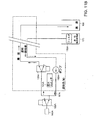
図11Aは圧力制御されたコンジット87A−145Dにより供給されるプリントヘッド145A−145Dのシステムの概略ブロック図である。図に示すように、結合剤供給システムは複数のプリントヘッド145A、145B、145C、145Dを含み、これらプリントヘッドは、複数の結合剤供給リザーバ175、112、114、116および廃液収容器155に接続されている。図のように、イエロー結合剤供給リザーバ112はイエローに指定されたプリントヘッド145Bに接続され、マゼンタ結合剤供給リザーバ114はマゼンタに指定されたプリントヘッド145Cに、またシアン結合剤供給リザーバ116はシアンに指定されたプリントヘッド145Dに接続されている。透明結合剤供給リザーバ175は透明色に指定されたプリントヘッド145Aおよび色の指定されたプリントヘッド145B、145C、145Dのそれぞれに接続されている。すべてのプリントヘッド145A〜145Dは廃液収容器155に接続されている。詳細は以下に述べる。
Binder Supply FIG. 11A is a schematic block diagram of a system of
図11Bは、図11Aの、透明(無色)結合剤溶液をプリントするように指定されているプリントヘッド145Aに対する結合剤溶液供給装置を示す。通常の動作モードでは、バルブ122Aが開いて溶液を流し入れ、バルブ128Aが閉じて溶液をブロックする。ポンプ185Aはフィルタ118Aを通して透明結合剤溶液をリザーバ175から吸引し、この液を加圧して、コンジット87Aおよびバルブ122Aを通してプリントヘッド145Aに供給する。圧力スイッチ121Aは予め設定された圧力レベル(例えば、3psi(2.1×10⁴Pa))に達すると、ポンプ185Aの作動を停止するように構成されている。この機構により、プリントヘッド145Aの透明結合剤溶液の圧力はほぼ設定圧力レベルに維持される。
FIG. 11B shows the binder solution supply apparatus for
別の動作モードでは、バルブ128Aが開いて溶液を流し入れ、リザーバ175からの結合剤溶液を、供給装置を通して循環させ、廃液収容器155に戻す。この構成により、例えば、プリンタが長時間にわたりアイドル状態のときに、供給装置内の結合剤溶液を定期的に入れ替えることができる。さらに別の動作モードでは、バルブ122Aが閉じて溶液をブロックし、例えば、プリンタが作動していないときに、プリントヘッド内の溶液が透明結合剤供給リザーバ175に戻るのを防ぐ。
In another mode of operation, the
図11Cは図11Aの、イエロー結合剤溶液をプリントするように指定されているプリントヘッド145Bに対する結合剤溶液供給装置を示す。この供給装置の図11Bに示す透明結合剤供給装置と異なる点は、この供給装置にバルブ120Bが追加されている点であり、このバルブ構成により、ポンプ185Bが必要に応じて、透明結合剤溶液供給リザーバ175またはイエロー結合剤供給リザーバ112の一方から結合剤溶液を吸引できる。他のプリントヘッド145C、145Dは、イエローのプリントヘッド145Bと同様に、透明結合剤溶液か、または関連する着色結合剤溶液リザーバ114、116からの着色結合剤溶液のどちらかを供給される。
FIG. 11C shows the binder solution supply apparatus for
前述の供給装置では、バルブ120B〜120Dをすべて、透明結合剤をそれぞれのプリントヘッドに供給するように構成して、例えば、高速の造形速度でモノクロの造形物をプリントできる。これとは別に、各ヘッドに異なる色を供給して、着色された造形物をプリントできる。カラー・モードとモノクロ・モード間で切り替えが必要なとき、バルブ128B〜128Dを開いて、カラー・プリントヘッド供給装置きから廃液収容器155に不要な結合剤溶液を流し出す。
In the above-described supply apparatus, all the
均等物
3次元物体の模型を製作する方法および装置を、その特定の実施形態に関して図示し、説明してきたが、当業者には、添付の特許請求の範囲に定義された本発明の精神と範囲から逸脱することなく、形態または細部に各種の変更を加えるのが可能であることは理解されるであろう。これらおよび他のすべての均等物も特許請求の範囲に包含されるものとする。
Equivalents Although methods and apparatus for making models of three-dimensional objects have been illustrated and described with respect to specific embodiments thereof, those skilled in the art will recognize the spirit and scope of the invention as defined in the appended claims. It will be understood that various changes may be made in form or detail without departing from the invention. These and all other equivalents are intended to be encompassed by the claims.
22 上部デッキ
24 材料供給チャンバ
25 供給ピストン
26 造形チャンバ
27 造形テーブル
28 オーバーフロー・シュート
31 フィルタ
34 ブロワ−
81 バケット
82 取付け台
83 上部プレート
22
81
Claims (4)
前記造形チャンバを横断して移動するように取り付けられた複数のプリントヘッドと、
前記プリントヘッドの外部の少なくとも1つの結合剤供給源と、
各結合剤供給源を少なくとも1つのプリントヘッドに接続する複数のコンジットと、
前記プリントヘッドにコマンドを発行するソフトウェア命令を格納するコンピュータ読出し可能なメモリと、
を備え、
前記ソフトウェア命令がコマンドを発行して、プリントヘッドに対して、前記結合材供給源に含まれる着色結合剤溶液を、3次元物体の表面からその物体の内部に延びるバンド状に噴射するように命令し、前記バンドが前記3次元物体の縁部で先細り形状を有し、隣接する前記バンド間に、前記縁部から前記物体内部に延びる先細り形状の着色されないセクションを残す、
3次元物体を製作する装置。A modeling chamber that can be filled with a bed of modeling material;
A plurality of print heads mounted for movement across the build chamber;
At least one binder source external to the printhead;
A plurality of conduits connecting each binder supply to at least one printhead ;
A computer readable memory storing software instructions for issuing commands to the print head;
With
The software instruction issues a command to instruct the print head to spray the colored binder solution contained in the binder supply source in a band extending from the surface of the three-dimensional object into the object. The band has a tapered shape at the edge of the three-dimensional object, leaving a non-colored section of the tapered shape extending from the edge into the object between adjacent bands;
A device that produces 3D objects.
前記造形チャンバを横断して移動する複数のプリントヘッドを取り付け、
前記プリントヘッドの外部に少なくとも1つの結合剤供給源を設け、
各結合剤供給源を、複数のコンジットを通して少なくとも1つのプリントヘッドに接続し、
前記3次元物体の表面からその物体の内部に延びるバンドに前記結合材供給源に含まれる着色結合剤溶液を供給し、前記バンドが前記3次元物体の縁部で先細り形状を有し、隣接する前記バンド間に、前記縁部から前記3次元物体内部に延びる先細り形状の着色されないセクションを残す、
3次元物体を製作する方法。Providing a modeling chamber filled with a bed of modeling material;
Mounting a plurality of print heads moving across the build chamber;
Providing at least one binder supply outside the printhead;
Each binder source is connected to at least one printhead through a plurality of conduits;
A colored binder solution included in the binder supply source is supplied to a band extending from the surface of the three-dimensional object to the inside of the object, and the band has a tapered shape at an edge of the three-dimensional object and is adjacent to the band Leaving a non-colored section between the bands extending from the edge and into the interior of the three-dimensional object;
A method of manufacturing a three-dimensional object.
Applications Claiming Priority (2)
| Application Number | Priority Date | Filing Date | Title |
|---|---|---|---|
| US09/851,502 US6989115B2 (en) | 1996-12-20 | 2001-05-08 | Method and apparatus for prototyping a three-dimensional object |
| PCT/US2002/014591 WO2003016067A2 (en) | 2001-05-08 | 2002-05-08 | Method and apparatus for prototyping a three-dimensional object |
Related Child Applications (1)
| Application Number | Title | Priority Date | Filing Date |
|---|---|---|---|
| JP2008201111A Division JP4537476B2 (en) | 2001-05-08 | 2008-08-04 | Method and apparatus for manufacturing a model of a three-dimensional object |
Publications (3)
| Publication Number | Publication Date |
|---|---|
| JP2004538191A JP2004538191A (en) | 2004-12-24 |
| JP2004538191A5 JP2004538191A5 (en) | 2005-12-22 |
| JP4491230B2 true JP4491230B2 (en) | 2010-06-30 |
Family
ID=25310926
Family Applications (2)
| Application Number | Title | Priority Date | Filing Date |
|---|---|---|---|
| JP2003520600A Expired - Lifetime JP4491230B2 (en) | 2001-05-08 | 2002-05-08 | Method and apparatus for manufacturing a model of a three-dimensional object |
| JP2008201111A Expired - Lifetime JP4537476B2 (en) | 2001-05-08 | 2008-08-04 | Method and apparatus for manufacturing a model of a three-dimensional object |
Family Applications After (1)
| Application Number | Title | Priority Date | Filing Date |
|---|---|---|---|
| JP2008201111A Expired - Lifetime JP4537476B2 (en) | 2001-05-08 | 2008-08-04 | Method and apparatus for manufacturing a model of a three-dimensional object |
Country Status (7)
| Country | Link |
|---|---|
| US (1) | US6989115B2 (en) |
| EP (2) | EP1385704B1 (en) |
| JP (2) | JP4491230B2 (en) |
| AT (1) | ATE533610T1 (en) |
| CA (1) | CA2447573C (en) |
| HK (1) | HK1059761A1 (en) |
| WO (1) | WO2003016067A2 (en) |
Cited By (1)
| Publication number | Priority date | Publication date | Assignee | Title |
|---|---|---|---|---|
| KR20200004929A (en) * | 2017-04-20 | 2020-01-15 | 엑스와이지프린팅, 인크. | 3d printer |
Families Citing this family (259)
| Publication number | Priority date | Publication date | Assignee | Title |
|---|---|---|---|---|
| US6007318A (en) * | 1996-12-20 | 1999-12-28 | Z Corporation | Method and apparatus for prototyping a three-dimensional object |
| US7037382B2 (en) * | 1996-12-20 | 2006-05-02 | Z Corporation | Three-dimensional printer |
| US8735773B2 (en) | 2007-02-14 | 2014-05-27 | Conformis, Inc. | Implant device and method for manufacture |
| US8545569B2 (en) | 2001-05-25 | 2013-10-01 | Conformis, Inc. | Patient selectable knee arthroplasty devices |
| US8882847B2 (en) | 2001-05-25 | 2014-11-11 | Conformis, Inc. | Patient selectable knee joint arthroplasty devices |
| US7534263B2 (en) | 2001-05-25 | 2009-05-19 | Conformis, Inc. | Surgical tools facilitating increased accuracy, speed and simplicity in performing joint arthroplasty |
| US8083745B2 (en) | 2001-05-25 | 2011-12-27 | Conformis, Inc. | Surgical tools for arthroplasty |
| US7468075B2 (en) | 2001-05-25 | 2008-12-23 | Conformis, Inc. | Methods and compositions for articular repair |
| CA2388046A1 (en) * | 1999-11-05 | 2001-05-17 | Z Corporation | Material systems and methods of three-dimensional printing |
| US20010050031A1 (en) * | 2000-04-14 | 2001-12-13 | Z Corporation | Compositions for three-dimensional printing of solid objects |
| AU2001216453A1 (en) | 2000-09-25 | 2002-04-08 | Generis Gmbh | Method for producing a part using a deposition technique |
| US8951260B2 (en) | 2001-05-25 | 2015-02-10 | Conformis, Inc. | Surgical cutting guide |
| US8439926B2 (en) | 2001-05-25 | 2013-05-14 | Conformis, Inc. | Patient selectable joint arthroplasty devices and surgical tools |
| EP1389980B1 (en) | 2001-05-25 | 2011-04-06 | Conformis, Inc. | Methods and compositions for articular resurfacing |
| DE10216013B4 (en) | 2002-04-11 | 2006-12-28 | Generis Gmbh | Method and device for applying fluids |
| CN100506157C (en) * | 2002-05-10 | 2009-07-01 | 财团法人名古屋产业科学研究所 | Three-dimensional model |
| US7087109B2 (en) * | 2002-09-25 | 2006-08-08 | Z Corporation | Three dimensional printing material system and method |
| US20040080078A1 (en) * | 2002-10-25 | 2004-04-29 | Collins David C. | Methods and systems for producing a desired apparent coloring in an object produced through rapid prototyping |
| US7589868B2 (en) * | 2002-12-11 | 2009-09-15 | Agfa Graphics Nv | Method and apparatus for creating 3D-prints and a 3-D printing system |
| ATE370832T1 (en) * | 2003-05-01 | 2007-09-15 | Objet Geometries Ltd | RAPID PROTOTYPING APPARATUS |
| EP1475220A3 (en) * | 2003-05-09 | 2009-07-08 | FUJIFILM Corporation | Process for producing three-dimensional model, and three-dimensional model |
| WO2004106041A2 (en) * | 2003-05-23 | 2004-12-09 | Z Corporation | Apparatus and methods for 3d printing |
| US7807077B2 (en) | 2003-06-16 | 2010-10-05 | Voxeljet Technology Gmbh | Methods and systems for the manufacture of layered three-dimensional forms |
| US7141617B2 (en) * | 2003-06-17 | 2006-11-28 | The Board Of Trustees Of The University Of Illinois | Directed assembly of three-dimensional structures with micron-scale features |
| US7645403B2 (en) * | 2003-06-24 | 2010-01-12 | Hewlett-Packard Development Company, L.P. | Method of improving color quality in an object produced by solid freeform fabrication |
| US20050087897A1 (en) * | 2003-10-23 | 2005-04-28 | Nielsen Jeffrey A. | Systems and methods for reducing waste in solid freeform fabrication |
| DE102004008168B4 (en) | 2004-02-19 | 2015-12-10 | Voxeljet Ag | Method and device for applying fluids and use of the device |
| WO2005097476A2 (en) * | 2004-04-02 | 2005-10-20 | Z Corporation | Methods and apparatus for 3d printing |
| DE102004025374A1 (en) * | 2004-05-24 | 2006-02-09 | Technische Universität Berlin | Method and device for producing a three-dimensional article |
| US7387359B2 (en) * | 2004-09-21 | 2008-06-17 | Z Corporation | Apparatus and methods for servicing 3D printers |
| US7824001B2 (en) * | 2004-09-21 | 2010-11-02 | Z Corporation | Apparatus and methods for servicing 3D printers |
| AU2005299194A1 (en) * | 2004-10-26 | 2006-05-04 | 2089275 Ontario Ltd. | Method for the automated production of three-dimensional objects and textured substrates from two-dimensional or three-dimensional objects |
| US20060159869A1 (en) * | 2005-01-14 | 2006-07-20 | Laura Kramer | Reactive materials systems and methods for solid freeform fabrication of three-dimensional objects |
| US20060214335A1 (en) * | 2005-03-09 | 2006-09-28 | 3D Systems, Inc. | Laser sintering powder recycle system |
| US7357629B2 (en) * | 2005-03-23 | 2008-04-15 | 3D Systems, Inc. | Apparatus and method for aligning a removable build chamber within a process chamber |
| AU2006297137A1 (en) | 2005-09-30 | 2007-04-12 | Conformis Inc. | Joint arthroplasty devices |
| US7520740B2 (en) * | 2005-09-30 | 2009-04-21 | 3D Systems, Inc. | Rapid prototyping and manufacturing system and method |
| US20070126157A1 (en) * | 2005-12-02 | 2007-06-07 | Z Corporation | Apparatus and methods for removing printed articles from a 3-D printer |
| US8623026B2 (en) | 2006-02-06 | 2014-01-07 | Conformis, Inc. | Patient selectable joint arthroplasty devices and surgical tools incorporating anatomical relief |
| EP1981409B1 (en) | 2006-02-06 | 2017-01-11 | ConforMIS, Inc. | Patient selectable joint arthroplasty devices and surgical tools |
| EP2001656B1 (en) * | 2006-04-06 | 2014-10-15 | 3D Systems Incorporated | KiT FOR THE PRODUCTION OF THREE-DIMENSIONAL OBJECTS BY USE OF ELECTROMAGNETIC RADIATION |
| KR20100087411A (en) | 2006-04-21 | 2010-08-05 | 넥스트21 케이 케이 | Figure-forming composition, process for production of figures in three dimensions by using the composition and process for production of three-dimensional structures |
| US7832456B2 (en) * | 2006-04-28 | 2010-11-16 | Halliburton Energy Services, Inc. | Molds and methods of forming molds associated with manufacture of rotary drill bits and other downhole tools |
| US7979152B2 (en) | 2006-05-26 | 2011-07-12 | Z Corporation | Apparatus and methods for handling materials in a 3-D printer |
| DE102006030350A1 (en) | 2006-06-30 | 2008-01-03 | Voxeljet Technology Gmbh | Method for constructing a layer body |
| DE102006038858A1 (en) | 2006-08-20 | 2008-02-21 | Voxeljet Technology Gmbh | Self-hardening material and method for layering models |
| US20100069455A1 (en) | 2006-08-21 | 2010-03-18 | Next21 K.K. | Bone model, bone filler and process for producing bone filler |
| JP5405119B2 (en) | 2006-11-11 | 2014-02-05 | 株式会社ネクスト21 | Bone filler, controlled release carrier, and production method thereof |
| EP2664442B1 (en) * | 2006-12-08 | 2018-02-14 | 3D Systems Incorporated | Three dimensional printing material system |
| WO2008077850A2 (en) * | 2006-12-21 | 2008-07-03 | Agfa Graphics Nv | 3d-inkjet printing methods |
| WO2008086033A1 (en) * | 2007-01-10 | 2008-07-17 | Z Corporation | Three-dimensional printing material system with improved color, article performance, and ease of use |
| US20080170112A1 (en) * | 2007-01-17 | 2008-07-17 | Hull Charles W | Build pad, solid image build, and method for building build supports |
| EP2114312B1 (en) | 2007-02-14 | 2014-01-08 | ConforMIS, Inc. | Method for manufacture of an implant device |
| WO2008103450A2 (en) | 2007-02-22 | 2008-08-28 | Z Corporation | Three dimensional printing material system and method using plasticizer-assisted sintering |
| WO2008107866A1 (en) * | 2007-03-07 | 2008-09-12 | Objet Geometries Ltd. | Rapid production apparatus |
| US20080309665A1 (en) * | 2007-06-13 | 2008-12-18 | 3D Systems, Inc., A California Corporation | Distributed rapid prototyping |
| US7744364B2 (en) | 2007-06-21 | 2010-06-29 | Stratasys, Inc. | Extrusion tip cleaning assembly |
| US10226919B2 (en) | 2007-07-18 | 2019-03-12 | Voxeljet Ag | Articles and structures prepared by three-dimensional printing method |
| DE102007033434A1 (en) | 2007-07-18 | 2009-01-22 | Voxeljet Technology Gmbh | Method for producing three-dimensional components |
| EP2664443B1 (en) | 2007-07-25 | 2021-08-25 | Stratasys Ltd. | Solid freeform fabrication using a plurality of modeling materials |
| US7625200B2 (en) * | 2007-07-31 | 2009-12-01 | Stratasys, Inc. | Extrusion head for use in extrusion-based layered deposition modeling |
| US20090091591A1 (en) * | 2007-10-07 | 2009-04-09 | Yohanan Sivan | Printing Systems And Methods For Generating Relief Images |
| DE102007049058A1 (en) | 2007-10-11 | 2009-04-16 | Voxeljet Technology Gmbh | Material system and method for modifying properties of a plastic component |
| DE102007050679A1 (en) | 2007-10-21 | 2009-04-23 | Voxeljet Technology Gmbh | Method and device for conveying particulate material in the layered construction of models |
| DE102007050953A1 (en) | 2007-10-23 | 2009-04-30 | Voxeljet Technology Gmbh | Device for the layered construction of models |
| GB0818493D0 (en) * | 2008-10-09 | 2008-11-19 | Reedhycalog Uk Ltd | Drilling tool |
| DE102008058378A1 (en) | 2008-11-20 | 2010-05-27 | Voxeljet Technology Gmbh | Process for the layered construction of plastic models |
| US7991498B2 (en) | 2009-02-03 | 2011-08-02 | Objet Geometries Ltd. | Method and system for building painted three-dimensional objects |
| US8808297B2 (en) | 2009-02-24 | 2014-08-19 | Microport Orthopedics Holdings Inc. | Orthopedic surgical guide |
| US8808303B2 (en) | 2009-02-24 | 2014-08-19 | Microport Orthopedics Holdings Inc. | Orthopedic surgical guide |
| US9017334B2 (en) | 2009-02-24 | 2015-04-28 | Microport Orthopedics Holdings Inc. | Patient specific surgical guide locator and mount |
| US8545209B2 (en) * | 2009-03-31 | 2013-10-01 | Microjet Technology Co., Ltd. | Three-dimensional object forming apparatus and method for forming three-dimensional object |
| US8342833B2 (en) * | 2009-03-31 | 2013-01-01 | Microjet Technology Co., Ltd. | Three-dimensional object forming apparatus |
| BRPI1014917A2 (en) | 2009-04-16 | 2016-04-19 | Conformis Inc | "Patient specific joint arthroplasty devices for ligament repair" |
| DE102009030113A1 (en) | 2009-06-22 | 2010-12-23 | Voxeljet Technology Gmbh | Method and device for supplying fluids during the layering of models |
| JP5543740B2 (en) * | 2009-08-07 | 2014-07-09 | 株式会社コンピュータシステム研究所 | 3D model manufacturing method and 3D model |
| DE102009056695B4 (en) * | 2009-12-02 | 2012-03-29 | Prometal Rct Gmbh | Print head cleaning device |
| DE102010006939A1 (en) | 2010-02-04 | 2011-08-04 | Voxeljet Technology GmbH, 86167 | Device for producing three-dimensional models |
| US8222908B2 (en) * | 2010-02-16 | 2012-07-17 | Stratasys, Inc. | Capacitive detector for use in extrusion-based digital manufacturing systems |
| DE102010013732A1 (en) | 2010-03-31 | 2011-10-06 | Voxeljet Technology Gmbh | Device for producing three-dimensional models |
| DE102010013733A1 (en) | 2010-03-31 | 2011-10-06 | Voxeljet Technology Gmbh | Device for producing three-dimensional models |
| DE102010014969A1 (en) | 2010-04-14 | 2011-10-20 | Voxeljet Technology Gmbh | Device for producing three-dimensional models |
| DE102010015451A1 (en) | 2010-04-17 | 2011-10-20 | Voxeljet Technology Gmbh | Method and device for producing three-dimensional objects |
| CN201685457U (en) * | 2010-06-02 | 2010-12-29 | 研能科技股份有限公司 | Stereoscopic forming mechanism |
| DE102010027071A1 (en) | 2010-07-13 | 2012-01-19 | Voxeljet Technology Gmbh | Device for producing three-dimensional models by means of layer application technology |
| EP2654412B1 (en) | 2010-12-21 | 2019-10-16 | Stratasys Ltd. | Method and system for reuse of materials in additive manufacturing systems |
| DE102010056346A1 (en) | 2010-12-29 | 2012-07-05 | Technische Universität München | Method for the layered construction of models |
| DE102011007957A1 (en) | 2011-01-05 | 2012-07-05 | Voxeljet Technology Gmbh | Device and method for constructing a layer body with at least one body limiting the construction field and adjustable in terms of its position |
| US8512024B2 (en) | 2011-01-20 | 2013-08-20 | Makerbot Industries, Llc | Multi-extruder |
| DE202011003443U1 (en) | 2011-03-02 | 2011-12-23 | Bego Medical Gmbh | Device for the generative production of three-dimensional components |
| JP5703911B2 (en) * | 2011-04-01 | 2015-04-22 | セイコーエプソン株式会社 | Molding compound device |
| US9207355B2 (en) | 2011-05-26 | 2015-12-08 | Baker Hughes Incorporated | Method for physical modeling of reservoirs |
| DE102011111498A1 (en) | 2011-08-31 | 2013-02-28 | Voxeljet Technology Gmbh | Device for the layered construction of models |
| DE102011082873A1 (en) * | 2011-09-16 | 2013-03-21 | Bayerische Motoren Werke Aktiengesellschaft | Device for manufacturing three-dimensional mold parts for e.g. prototyping, has installation space, where layer of powder material is solidifyable by adding binder to layers of mold part and low pressure is generated in installation space |
| US9408686B1 (en) | 2012-01-20 | 2016-08-09 | Conformis, Inc. | Devices, systems and methods for manufacturing orthopedic implants |
| DE102012004213A1 (en) | 2012-03-06 | 2013-09-12 | Voxeljet Technology Gmbh | Method and device for producing three-dimensional models |
| JP5772668B2 (en) | 2012-03-08 | 2015-09-02 | カシオ計算機株式会社 | Three-dimensional modeling method, three-dimensional modeling complex, and three-dimensional modeling apparatus |
| US9486226B2 (en) | 2012-04-18 | 2016-11-08 | Conformis, Inc. | Tibial guides, tools, and techniques for resecting the tibial plateau |
| DE102012010272A1 (en) | 2012-05-25 | 2013-11-28 | Voxeljet Technology Gmbh | Method for producing three-dimensional models with special construction platforms and drive systems |
| US9675471B2 (en) | 2012-06-11 | 2017-06-13 | Conformis, Inc. | Devices, techniques and methods for assessing joint spacing, balancing soft tissues and obtaining desired kinematics for joint implant components |
| DE102012012363A1 (en) | 2012-06-22 | 2013-12-24 | Voxeljet Technology Gmbh | Apparatus for building up a layer body with a storage or filling container movable along the discharge container |
| KR101572009B1 (en) | 2012-09-05 | 2015-11-25 | 아프레시아 파마슈티칼스 컴퍼니 | Three-dimensional printing system and equipment assembly |
| US8888480B2 (en) | 2012-09-05 | 2014-11-18 | Aprecia Pharmaceuticals Company | Three-dimensional printing system and equipment assembly |
| US9636229B2 (en) | 2012-09-20 | 2017-05-02 | Conformis, Inc. | Solid freeform fabrication of implant components |
| JP2015532858A (en) | 2012-09-21 | 2015-11-16 | コンフォーミス・インコーポレイテッドConforMIS, Inc. | Method and system for optimizing the design and manufacture of implant components using solid freeform manufacturing |
| DE102012109262A1 (en) * | 2012-09-28 | 2014-04-03 | Bundesrepublik Deutschland, vertreten durch das Bundesministerium für Wirtschaft und Technologie, dieses vertreten durch den Präsidenten der BAM, Bundesanstalt für Materialforschung und -prüfung | Method for stabilizing a powder bed by means of negative pressure for additive manufacturing |
| DE102012020000A1 (en) | 2012-10-12 | 2014-04-17 | Voxeljet Ag | 3D multi-stage process |
| DE102013004940A1 (en) | 2012-10-15 | 2014-04-17 | Voxeljet Ag | Method and device for producing three-dimensional models with tempered printhead |
| DE102012022859A1 (en) | 2012-11-25 | 2014-05-28 | Voxeljet Ag | Construction of a 3D printing device for the production of components |
| DE102013003303A1 (en) | 2013-02-28 | 2014-08-28 | FluidSolids AG | Process for producing a molded part with a water-soluble casting mold and material system for its production |
| EP2968994B1 (en) | 2013-03-15 | 2018-08-15 | Aprecia Pharmaceuticals LLC | Rapid disperse dosage form containing levetiracetam |
| US9643362B2 (en) * | 2013-03-15 | 2017-05-09 | Microsoft Technology Licensing, Llc | Full color three-dimensional object fabrication |
| EP3007879B1 (en) * | 2013-06-10 | 2019-02-13 | Renishaw Plc. | Selective laser solidification apparatus and method |
| US11077607B2 (en) * | 2013-10-21 | 2021-08-03 | Made In Space, Inc. | Manufacturing in microgravity and varying external force environments |
| EP2851179B1 (en) * | 2013-09-19 | 2017-11-22 | SDD Holding B.V. | Device for printing simultaneously three dimensional objects |
| US11292622B2 (en) | 2013-10-07 | 2022-04-05 | Shay C. Colson | 3D printed vehicle packaging |
| US11292241B2 (en) | 2016-05-25 | 2022-04-05 | Shay C. Colson | 3-D packaging and shipping based on aggregate data |
| US11716211B2 (en) | 2016-10-01 | 2023-08-01 | James L. Schmeling | 3D-printed packaging with blockchain integration |
| US10981680B2 (en) | 2013-10-07 | 2021-04-20 | Shay C. Colson | 3-D printed package customization |
| US9248611B2 (en) | 2013-10-07 | 2016-02-02 | David A. Divine | 3-D printed packaging |
| US10676219B2 (en) | 2016-10-01 | 2020-06-09 | Shay C. Colson | Printing packaging in expanded material |
| KR101346704B1 (en) | 2013-10-18 | 2013-12-31 | 이재식 | 3-dimensional printer being capable of forming muiti-color products |
| DE102013018182A1 (en) | 2013-10-30 | 2015-04-30 | Voxeljet Ag | Method and device for producing three-dimensional models with binder system |
| CN104647754A (en) | 2013-11-18 | 2015-05-27 | 精工爱普生株式会社 | Three-dimensional shaped object, three-dimensional shaped object manufacturing method and apparatus, method of controlling three-dimensional shaped object manufacturing apparatus, and program for controlling three-dimensional shaped object manufacturing apparatus |
| US9744726B2 (en) * | 2013-11-25 | 2017-08-29 | Xerox Corporation | 3D print manufacturing of packages with personalized labeling technology |
| DE102013018031A1 (en) | 2013-12-02 | 2015-06-03 | Voxeljet Ag | Swap body with movable side wall |
| JP6264006B2 (en) | 2013-12-10 | 2018-01-24 | セイコーエプソン株式会社 | Modeling method and modeling apparatus |
| DE102013020491A1 (en) | 2013-12-11 | 2015-06-11 | Voxeljet Ag | 3D infiltration process |
| DE102013021091A1 (en) | 2013-12-18 | 2015-06-18 | Voxeljet Ag | 3D printing process with rapid drying step |
| EP2886307A1 (en) | 2013-12-20 | 2015-06-24 | Voxeljet AG | Device, special paper and method for the production of moulded components |
| ES2745763T3 (en) * | 2013-12-23 | 2020-03-03 | The Exone Co | Methods and systems for three-dimensional printing using multiple binder fluids |
| US20160325495A1 (en) * | 2013-12-23 | 2016-11-10 | The Exone Company | Methods and Systems for Three-Dimensional Printing Utilizing a Jetted-Particle Binder Fluid |
| JP2015131398A (en) * | 2014-01-09 | 2015-07-23 | セイコーエプソン株式会社 | Method for manufacturing three-dimensional molded article, apparatus for manufacturing three-dimensional molded article, ink set, and three-dimensional molded article |
| JP6387614B2 (en) * | 2014-01-09 | 2018-09-12 | セイコーエプソン株式会社 | Manufacturing method of three-dimensional structure and ink set |
| JP6570542B2 (en) | 2014-01-16 | 2019-09-04 | ヒューレット−パッカード デベロップメント カンパニー エル.ピー.Hewlett‐Packard Development Company, L.P. | 3D object generation |
| WO2015108551A1 (en) * | 2014-01-16 | 2015-07-23 | Hewlett-Packard Development Company, L.P. | Generating three-dimensional objects |
| RU2650155C2 (en) | 2014-01-16 | 2018-04-09 | Хьюлетт-Паккард Дивелопмент Компани, Л.П. | Formation of three-dimensional objects |
| DK3094469T3 (en) | 2014-01-16 | 2019-12-16 | Hewlett Packard Development Co | GENERATION OF A THREE-DIMENSIONAL ITEM |
| CN105916664B (en) * | 2014-01-16 | 2019-04-19 | 惠普发展公司,有限责任合伙企业 | Generate three-dimension object |
| WO2015111059A1 (en) | 2014-01-26 | 2015-07-30 | Stratasys Ltd. | Coloring of three-dimensional printed objects |
| US9415546B2 (en) | 2014-01-29 | 2016-08-16 | Xerox Corporation | System and method for controlling material drop volume in three dimensional object printing |
| WO2015117054A1 (en) * | 2014-02-02 | 2015-08-06 | Worcester Polytechnic Institute | Method and system for fabricating thermal insulation for retrofit applications |
| US10307970B2 (en) * | 2014-02-20 | 2019-06-04 | Made In Space, Inc. | In-situ resource preparation and utilization methods |
| JP2015174427A (en) * | 2014-03-18 | 2015-10-05 | セイコーエプソン株式会社 | Three-dimensional shaped object production apparatus, three-dimensional shaped object production method, and three-dimensional shaped object |
| WO2015141782A1 (en) * | 2014-03-19 | 2015-09-24 | シーメット株式会社 | Print head unit, three-dimensional additive layer manufacturing device, three-dimensional additive layer manufacturing method, and manufacturing product |
| US10232605B2 (en) | 2014-03-21 | 2019-03-19 | Carbon, Inc. | Method for three-dimensional fabrication with gas injection through carrier |
| JP6289201B2 (en) * | 2014-03-26 | 2018-03-07 | 株式会社ミマキエンジニアリング | Ink for manufacturing a three-dimensional structure and its use |
| DE102014004692A1 (en) | 2014-03-31 | 2015-10-15 | Voxeljet Ag | Method and apparatus for 3D printing with conditioned process control |
| US9162509B1 (en) * | 2014-03-31 | 2015-10-20 | Xerox Corporation | System for detecting inoperative inkjets in printheads ejecting clear ink using thermal substrates |
| JP6519100B2 (en) | 2014-04-23 | 2019-05-29 | セイコーエプソン株式会社 | Sinter-forming method, liquid binder, and sinter-formed product |
| JP6461488B2 (en) * | 2014-05-21 | 2019-01-30 | 株式会社ミマキエンジニアリング | Forming device for forming three-dimensional structures |
| DE102014007584A1 (en) | 2014-05-26 | 2015-11-26 | Voxeljet Ag | 3D reverse printing method and apparatus |
| GB2542044B (en) | 2014-06-04 | 2020-06-17 | Mitsubishi Hitachi Power Sys | Repair system, repair-data providing apparatus and repair-data generation method |
| CA2952633C (en) | 2014-06-20 | 2018-03-06 | Velo3D, Inc. | Apparatuses, systems and methods for three-dimensional printing |
| TW201609934A (en) | 2014-07-01 | 2016-03-16 | 精工愛普生股份有限公司 | Three-dimension formation composition, method of manufacturing three-dimensional structure, and three-dimensional structure |
| DE102014109706A1 (en) | 2014-07-10 | 2016-01-14 | Bundesrepublik Deutschland, Vertreten Durch Den Bundesminister Für Wirtschaft Und Energie, Dieser Vertreten Durch Den Präsidenten Der Bundesanstalt Für Materialforschung Und -Prüfung (Bam) | Construction and use of a geometrically densely packed powder layer |
| JP2016033959A (en) * | 2014-07-31 | 2016-03-10 | 株式会社東芝 | On-load tap switcher, and changeover switch for on-load tap switcher |
| JP2016033940A (en) * | 2014-07-31 | 2016-03-10 | 株式会社東芝 | Gas isolation transformer |
| CN106573294B (en) | 2014-08-02 | 2021-01-01 | 沃克斯艾捷特股份有限公司 | Method and casting mould, in particular for a cold casting method |
| KR102199789B1 (en) * | 2014-08-07 | 2021-01-08 | 삼성전자주식회사 | A object forming apparatus and a method for controlling the object forming apparatus |
| CN104260341B (en) * | 2014-08-19 | 2016-09-21 | 英华达(上海)科技有限公司 | A kind of bond material shower nozzle and the 3D Method of printing of paint sprayer and system |
| CN104260353B (en) | 2014-09-24 | 2017-01-25 | 英华达(上海)科技有限公司 | Rapid molding system and rapid molding method |
| JP6397293B2 (en) * | 2014-09-29 | 2018-09-26 | 株式会社Screenホールディングス | 3D modeling apparatus and manufacturing method of 3D model |
| US10052823B2 (en) | 2014-10-08 | 2018-08-21 | Xerox Corporation | System and method for test pattern formation during three-dimensional object printing |
| CN107073826B (en) * | 2014-11-20 | 2020-02-18 | 惠普发展公司有限责任合伙企业 | System and method for generating three-dimensional objects |
| JP6421562B2 (en) * | 2014-11-25 | 2018-11-14 | セイコーエプソン株式会社 | Three-dimensional structure manufacturing method and three-dimensional structure manufacturing apparatus |
| JP6532390B2 (en) * | 2014-12-02 | 2019-06-19 | 株式会社ミマキエンジニアリング | Three-dimensional object formation apparatus and three-dimensional object formation method |
| US20160151975A1 (en) | 2014-12-02 | 2016-06-02 | Mimaki Engineering Co., Ltd. | Apparatus for forming three-dimensional object and method for forming three-dimensional object |
| CN105751494A (en) * | 2014-12-19 | 2016-07-13 | 研能科技股份有限公司 | Rapid prototyping apparatus for page width jet printing |
| CN105751497A (en) * | 2014-12-19 | 2016-07-13 | 研能科技股份有限公司 | Rapid prototyping apparatus for page width jet printing |
| CN105751498A (en) * | 2014-12-19 | 2016-07-13 | 研能科技股份有限公司 | Rapid prototyping apparatus for page width jet printing |
| CN105751496A (en) * | 2014-12-19 | 2016-07-13 | 研能科技股份有限公司 | Rapid prototyping apparatus for page width jet printing |
| DE102015006533A1 (en) | 2014-12-22 | 2016-06-23 | Voxeljet Ag | Method and device for producing 3D molded parts with layer construction technique |
| CN105835359A (en) * | 2015-01-16 | 2016-08-10 | 研能科技股份有限公司 | Printing module of rapid prototyping device |
| TWI606914B (en) * | 2015-01-16 | 2017-12-01 | 研能科技股份有限公司 | Printing module of rapid prototyping apparatus |
| KR101995650B1 (en) * | 2015-01-30 | 2019-09-24 | 휴렛-팩커드 디벨롭먼트 컴퍼니, 엘.피. | 3D object manufacturing technique |
| TWI604943B (en) * | 2015-01-30 | 2017-11-11 | 研能科技股份有限公司 | Printing module of rapid prototyping apparatus |
| CN105984147B (en) * | 2015-02-04 | 2018-11-30 | 三纬国际立体列印科技股份有限公司 | Three-dimensional printing device |
| JP6450017B2 (en) * | 2015-03-05 | 2019-01-09 | ヒューレット−パッカード デベロップメント カンパニー エル.ピー.Hewlett‐Packard Development Company, L.P. | 3D object generation |
| DE102015103726A1 (en) * | 2015-03-13 | 2016-09-15 | Exone Gmbh | 3D printer with coater and coater cleaning device |
| CN106032061B (en) * | 2015-03-16 | 2018-05-22 | 研能科技股份有限公司 | Stereoscopic moulding device |
| DE102015003372A1 (en) | 2015-03-17 | 2016-09-22 | Voxeljet Ag | Method and device for producing 3D molded parts with double recoater |
| GB201505458D0 (en) | 2015-03-30 | 2015-05-13 | Renishaw Plc | Additive manufacturing apparatus and methods |
| US9286554B1 (en) | 2015-04-01 | 2016-03-15 | Xerox Corporation | System and method for halftone printing in a three-dimensional object printer |
| EP3271146B1 (en) * | 2015-05-15 | 2021-06-30 | Hewlett-Packard Development Company, L.P. | Coalescing agent concentrations and contone densities for three-dimensional objects |
| DE102015006363A1 (en) | 2015-05-20 | 2016-12-15 | Voxeljet Ag | Phenolic resin method |
| CN107530966B (en) * | 2015-07-09 | 2021-06-18 | 惠普发展公司有限责任合伙企业 | Generating three-dimensional objects with target surface roughness |
| US9707785B2 (en) | 2015-07-16 | 2017-07-18 | Xerox Corporation | System and method for analysis of compact printed test patterns |
| JP2017030177A (en) * | 2015-07-30 | 2017-02-09 | セイコーエプソン株式会社 | Three-dimensional object molding apparatus, method for controlling three-dimensional object molding apparatus, production method of three-dimensional object using three-dimensional object molding apparatus, information processing device communicable with three-dimensional object molding apparatus, and three-dimensional object molding system |
| JP6582684B2 (en) | 2015-07-30 | 2019-10-02 | セイコーエプソン株式会社 | Three-dimensional object modeling apparatus, information processing apparatus capable of communicating with three-dimensional object modeling apparatus, control method for three-dimensional object modeling apparatus, three-dimensional object production method using three-dimensional object modeling apparatus, and three-dimensional object modeling system |
| CN106427249B (en) * | 2015-08-12 | 2019-06-07 | 三纬国际立体列印科技股份有限公司 | The type information processing method of powder type 3D printing |
| AU2016310470A1 (en) | 2015-08-21 | 2018-02-22 | Aprecia Pharmaceuticals LLC | Three-dimensional printing system and equipment assembly |
| DE102015011503A1 (en) | 2015-09-09 | 2017-03-09 | Voxeljet Ag | Method for applying fluids |
| DE102015011790A1 (en) | 2015-09-16 | 2017-03-16 | Voxeljet Ag | Device and method for producing three-dimensional molded parts |
| US10395561B2 (en) | 2015-12-07 | 2019-08-27 | Humanetics Innovative Solutions, Inc. | Three-dimensionally printed internal organs for crash test dummy |
| US10733911B2 (en) | 2015-10-14 | 2020-08-04 | Humanetics Innovative Solutions, Inc. | Three-dimensional ribs and method of three-dimensional printing of ribs for crash test dummy |
| US10065270B2 (en) | 2015-11-06 | 2018-09-04 | Velo3D, Inc. | Three-dimensional printing in real time |
| US10471697B2 (en) | 2015-11-13 | 2019-11-12 | R3 Printing, Inc. | System and method for on-demand colorization for extrusion-based additive construction |
| JP6699287B2 (en) * | 2015-11-20 | 2020-05-27 | 株式会社リコー | 3D modeling device and 3D modeling system |
| US10913259B2 (en) | 2015-11-20 | 2021-02-09 | Ricoh Company, Ltd. | Three-dimensional shaping apparatus and three-dimensional shaping system |
| DE102015015353A1 (en) * | 2015-12-01 | 2017-06-01 | Voxeljet Ag | Method and device for producing three-dimensional components by means of an excess quantity sensor |
| WO2017100695A1 (en) | 2015-12-10 | 2017-06-15 | Velo3D, Inc. | Skillful three-dimensional printing |
| JP2017105101A (en) * | 2015-12-11 | 2017-06-15 | 株式会社ミマキエンジニアリング | Three-dimensional molded object, and three-dimensional molding apparatus and method for producing the same |
| DE102015122460A1 (en) * | 2015-12-21 | 2017-06-22 | Cl Schutzrechtsverwaltungs Gmbh | Device for producing three-dimensional objects |
| JP6979963B2 (en) | 2016-02-18 | 2021-12-15 | ヴェロ・スリー・ディー・インコーポレイテッド | Accurate 3D printing |
| US10696036B2 (en) | 2016-03-01 | 2020-06-30 | Ricoh Company, Ltd. | Apparatus and method of fabricating three-dimensional object |
| CN105728717A (en) * | 2016-04-28 | 2016-07-06 | 苏州艾泰普机械有限公司 | 3D printer |
| CN108602245B (en) * | 2016-05-12 | 2021-01-01 | 惠普发展公司,有限责任合伙企业 | Airflow assembly |
| US10765658B2 (en) | 2016-06-22 | 2020-09-08 | Mastix LLC | Oral compositions delivering therapeutically effective amounts of cannabinoids |
| US11691343B2 (en) | 2016-06-29 | 2023-07-04 | Velo3D, Inc. | Three-dimensional printing and three-dimensional printers |
| WO2018005439A1 (en) | 2016-06-29 | 2018-01-04 | Velo3D, Inc. | Three-dimensional printing and three-dimensional printers |
| DE102016008656B4 (en) | 2016-07-20 | 2023-03-30 | Voxeljet Ag | Device and method for producing 3D molded parts and use of a film and a vacuum medium |
| CN109153178A (en) | 2016-07-22 | 2019-01-04 | 惠普发展公司,有限责任合伙企业 | Displacement in 3D printing |
| EP3436240B1 (en) * | 2016-07-29 | 2022-08-31 | Hewlett-Packard Development Company, L.P. | Build material layer quality level determination |
| US9987682B2 (en) | 2016-08-03 | 2018-06-05 | 3Deo, Inc. | Devices and methods for three-dimensional printing |
| CN107876778A (en) * | 2016-09-30 | 2018-04-06 | 珠海天威飞马打印耗材有限公司 | The metal three-dimensional printer and its Method of printing of a kind of fused glass pellet |
| US10150282B2 (en) | 2016-10-14 | 2018-12-11 | Xerox Corporation | System and method for additive manufacture of chemical delivery devices using halftone screening |
| US20180111198A1 (en) * | 2016-10-21 | 2018-04-26 | Velo3D, Inc. | Operation of three-dimensional printer components |
| WO2018080498A1 (en) | 2016-10-27 | 2018-05-03 | Hewlett-Packard Development Company, L.P. | Valves for fluid ejection devices |
| WO2018128695A2 (en) | 2016-11-07 | 2018-07-12 | Velo3D, Inc. | Gas flow in three-dimensional printing |
| DE102016013610A1 (en) | 2016-11-15 | 2018-05-17 | Voxeljet Ag | Intra-head printhead maintenance station for powder bed-based 3D printing |
| US20180186082A1 (en) | 2017-01-05 | 2018-07-05 | Velo3D, Inc. | Optics in three-dimensional printing |
| US10919286B2 (en) * | 2017-01-13 | 2021-02-16 | GM Global Technology Operations LLC | Powder bed fusion system with point and area scanning laser beams |
| KR102233013B1 (en) | 2017-02-10 | 2021-03-26 | 휴렛-팩커드 디벨롭먼트 컴퍼니, 엘.피. | Fusion module |
| US10449710B2 (en) * | 2017-02-17 | 2019-10-22 | Thermwood Corporation | Methods and apparatus for compressing material during additive manufacturing |
| US10315252B2 (en) | 2017-03-02 | 2019-06-11 | Velo3D, Inc. | Three-dimensional printing of three-dimensional objects |
| US10449696B2 (en) | 2017-03-28 | 2019-10-22 | Velo3D, Inc. | Material manipulation in three-dimensional printing |
| CN108724731B (en) * | 2017-04-21 | 2020-06-09 | 三纬国际立体列印科技股份有限公司 | Spray head cleaning module |
| TWI711487B (en) * | 2017-04-21 | 2020-12-01 | 三緯國際立體列印科技股份有限公司 | Cleaning module of painting pen |
| JP6441415B1 (en) * | 2017-06-27 | 2018-12-19 | ローランドディー.ジー.株式会社 | 3D modeling equipment |
| DE102017006860A1 (en) | 2017-07-21 | 2019-01-24 | Voxeljet Ag | Method and device for producing 3D molded parts with spectrum converter |
| US11465342B2 (en) * | 2017-07-28 | 2022-10-11 | Hewlett-Packard Development Company, L.P. | Three-dimensional printer |
| CN109421264A (en) * | 2017-08-30 | 2019-03-05 | 三纬国际立体列印科技股份有限公司 | Ink ejecting method and three-dimensional printing device |
| DE102017122849A1 (en) | 2017-10-02 | 2019-04-04 | Stefan Fischer | Fluid supply system for a 3D printer |
| EP3486004B1 (en) * | 2017-11-16 | 2021-09-15 | CL Schutzrechtsverwaltungs GmbH | Build material application device and apparatus for additively manufacturing three-dimensional objects |
| US10272525B1 (en) | 2017-12-27 | 2019-04-30 | Velo3D, Inc. | Three-dimensional printing systems and methods of their use |
| US10144176B1 (en) | 2018-01-15 | 2018-12-04 | Velo3D, Inc. | Three-dimensional printing systems and methods of their use |
| FR3076760B1 (en) * | 2018-01-15 | 2020-02-07 | Chanel Parfums Beaute | PROCESS FOR AFTER-TREATMENT OF A PART OBTAINED BY ADDITIVE MANUFACTURE FROM A POWDER OF A PLASTIC MATERIAL |
| US10814388B2 (en) | 2018-01-24 | 2020-10-27 | General Electric Company | Heated gas circulation system for an additive manufacturing machine |
| US10814395B2 (en) * | 2018-01-24 | 2020-10-27 | General Electric Company | Heated gas circulation system for an additive manufacturing machine |
| US20210402697A1 (en) * | 2018-04-30 | 2021-12-30 | Hewlett-Packard Development Company, L.P. | Computations of values for build material recyclability ratio selections |
| DE102018006473A1 (en) | 2018-08-16 | 2020-02-20 | Voxeljet Ag | Method and device for the production of 3D molded parts by means of layer construction technology by means of a closure device |
| US11312071B2 (en) | 2018-11-12 | 2022-04-26 | Ossur Iceland Ehf | Additive manufacturing system, method and corresponding components for making elastomeric structures |
| DE102019000796A1 (en) | 2019-02-05 | 2020-08-06 | Voxeljet Ag | Exchangeable process unit |
| CN114555266A (en) * | 2019-05-23 | 2022-05-27 | 通用电气公司 | Additive manufacturing apparatus and method |
| KR102078813B1 (en) * | 2019-07-29 | 2020-02-19 | 주식회사 에스에프에스 | 3D printer and alignment method of job box |
| DE102019122302A1 (en) | 2019-08-20 | 2021-02-25 | Kumovis GmbH | Print head for an additive manufacturing system as well as an additive manufacturing system |
| DE102019122291A1 (en) | 2019-08-20 | 2021-02-25 | Kumovis GmbH | Positioning system for an additive manufacturing system as well as an additive manufacturing system |
| DE102019122286A1 (en) | 2019-08-20 | 2021-02-25 | Kumovis GmbH | Floor element for an additive manufacturing system and additive manufacturing system |
| KR102113758B1 (en) * | 2019-10-08 | 2020-06-03 | 주식회사 에스앤티 | Powder 3D printer |
| KR102084892B1 (en) * | 2019-10-08 | 2020-05-26 | 주식회사 에스앤티 | Powder feeding device and 3D printer having the same |
| KR102084893B1 (en) * | 2019-10-08 | 2020-05-26 | 주식회사 에스앤티 | 3D printer having powder cleaner |
| KR102100353B1 (en) * | 2019-10-08 | 2020-04-13 | 주식회사 에스앤티 | 3D printer having printing head device |
| KR102100351B1 (en) * | 2019-10-08 | 2020-04-13 | 주식회사 에스앤티 | Process stage and 3D printer having the same |
| DE102019007595A1 (en) | 2019-11-01 | 2021-05-06 | Voxeljet Ag | 3D PRINTING PROCESS AND MOLDED PART MANUFACTURED WITH LIGNINE SULPHATE |
| CN114727871A (en) | 2019-11-12 | 2022-07-08 | 奥索冰岛有限公司 | Ventilated prosthetic liner |
| WO2021212110A1 (en) | 2020-04-17 | 2021-10-21 | Eagle Engineered Solutions, Inc. | Powder spreading apparatus and system |
| EP4237226A1 (en) * | 2020-10-29 | 2023-09-06 | General Electric Company | Print head assembly and methods for using the same |
| CN116901435A (en) * | 2021-09-18 | 2023-10-20 | 重庆理工大学 | High-quality 3D printer and printing device thereof |
Family Cites Families (40)
| Publication number | Priority date | Publication date | Assignee | Title |
|---|---|---|---|---|
| US2775758A (en) | 1951-05-25 | 1956-12-25 | Munz Otto John | Photo-glyph recording |
| US3428503A (en) | 1964-10-26 | 1969-02-18 | Lloyd D Beckerle | Three-dimensional reproduction method |
| DE2623823A1 (en) * | 1976-05-28 | 1977-12-08 | Sapco Systemanalyse & Projektb | DEVICE FOR THE SUPPLY OF GRANULATE OR POWDERED PLASTICS UNDER VACUUM |
| US4247508B1 (en) | 1979-12-03 | 1996-10-01 | Dtm Corp | Molding process |
| US5076869A (en) | 1986-10-17 | 1991-12-31 | Board Of Regents, The University Of Texas System | Multiple material systems for selective beam sintering |
| US5296062A (en) | 1986-10-17 | 1994-03-22 | The Board Of Regents, The University Of Texas System | Multiple material systems for selective beam sintering |
| US5017753A (en) | 1986-10-17 | 1991-05-21 | Board Of Regents, The University Of Texas System | Method and apparatus for producing parts by selective sintering |
| US5155324A (en) | 1986-10-17 | 1992-10-13 | Deckard Carl R | Method for selective laser sintering with layerwise cross-scanning |
| US4863538A (en) | 1986-10-17 | 1989-09-05 | Board Of Regents, The University Of Texas System | Method and apparatus for producing parts by selective sintering |
| US4944817A (en) | 1986-10-17 | 1990-07-31 | Board Of Regents, The University Of Texas System | Multiple material systems for selective beam sintering |
| WO1988002677A2 (en) | 1986-10-17 | 1988-04-21 | Board Of Regents, The University Of Texas System | Method and apparatus for producing parts by selective sintering |
| EP0289116A1 (en) | 1987-03-04 | 1988-11-02 | Westinghouse Electric Corporation | Method and device for casting powdered materials |
| DE3713794A1 (en) | 1987-04-24 | 1988-11-10 | Siemens Ag | DEVICE FOR CLEANING AND SEALING THE NOZZLE SURFACE OF AN INK HEAD |
| US5015312A (en) * | 1987-09-29 | 1991-05-14 | Kinzie Norman F | Method and apparatus for constructing a three-dimensional surface of predetermined shape and color |
| GB2233928B (en) * | 1989-05-23 | 1992-12-23 | Brother Ind Ltd | Apparatus and method for forming three-dimensional article |
| US5053090A (en) | 1989-09-05 | 1991-10-01 | Board Of Regents, The University Of Texas System | Selective laser sintering with assisted powder handling |
| US5088047A (en) | 1989-10-16 | 1992-02-11 | Bynum David K | Automated manufacturing system using thin sections |
| US5121329A (en) | 1989-10-30 | 1992-06-09 | Stratasys, Inc. | Apparatus and method for creating three-dimensional objects |
| US5387380A (en) | 1989-12-08 | 1995-02-07 | Massachusetts Institute Of Technology | Three-dimensional printing techniques |
| US5204055A (en) * | 1989-12-08 | 1993-04-20 | Massachusetts Institute Of Technology | Three-dimensional printing techniques |
| US5127037A (en) | 1990-08-15 | 1992-06-30 | Bynum David K | Apparatus for forming a three-dimensional reproduction of an object from laminations |
| US5155321A (en) | 1990-11-09 | 1992-10-13 | Dtm Corporation | Radiant heating apparatus for providing uniform surface temperature useful in selective laser sintering |
| WO1992008592A1 (en) | 1990-11-09 | 1992-05-29 | Dtm Corporation | Controlled gas flow for selective laser sintering |
| ES2081564T3 (en) * | 1991-01-31 | 1996-03-16 | Texas Instruments Inc | METHOD AND SYSTEM FOR THE MANUFACTURE, CONTROLLED BY COMPUTER, OF THREE-DIMENSIONAL OBJECTS FROM COMPUTER DATA. |
| US5252264A (en) | 1991-11-08 | 1993-10-12 | Dtm Corporation | Apparatus and method for producing parts with multi-directional powder delivery |
| US5342919A (en) | 1992-11-23 | 1994-08-30 | Dtm Corporation | Sinterable semi-crystalline powder and near-fully dense article formed therewith |
| US5490882A (en) | 1992-11-30 | 1996-02-13 | Massachusetts Institute Of Technology | Process for removing loose powder particles from interior passages of a body |
| US5352405A (en) | 1992-12-18 | 1994-10-04 | Dtm Corporation | Thermal control of selective laser sintering via control of the laser scan |
| WO1994019112A2 (en) | 1993-02-18 | 1994-09-01 | Massachusetts Institute Of Technology | High speed, high quality three dimensional printing |
| US6146567A (en) * | 1993-02-18 | 2000-11-14 | Massachusetts Institute Of Technology | Three dimensional printing methods |
| SE504560C2 (en) | 1993-05-12 | 1997-03-03 | Ralf Larson | Method and apparatus for the layered preparation of bodies from powder |
| DE4417083A1 (en) | 1994-05-16 | 1995-11-23 | Eos Electro Optical Syst | Coating device, in particular for a device for stereolithographically forming a three-dimensional object |
| WO1995034468A1 (en) | 1994-06-14 | 1995-12-21 | Soligen, Inc. | Powder handling apparatus for additive fabrication equipment |
| US5859775A (en) | 1994-10-19 | 1999-01-12 | Bpm Technology, Inc. | Apparatus and method including deviation sensing and recovery features for making three-dimensional articles |
| DE69621001T2 (en) * | 1995-02-01 | 2003-04-03 | 3D Systems Inc | FAST SMOOTHING PROCESS FOR THREE-DIMENSIONAL OBJECTS PRODUCED IN LAYERS |
| US6136252A (en) * | 1995-09-27 | 2000-10-24 | 3D Systems, Inc. | Apparatus for electro-chemical deposition with thermal anneal chamber |
| US5902441A (en) | 1996-09-04 | 1999-05-11 | Z Corporation | Method of three dimensional printing |
| US6007318A (en) * | 1996-12-20 | 1999-12-28 | Z Corporation | Method and apparatus for prototyping a three-dimensional object |
| US6612824B2 (en) * | 1999-03-29 | 2003-09-02 | Minolta Co., Ltd. | Three-dimensional object molding apparatus |
| US6676892B2 (en) * | 2000-06-01 | 2004-01-13 | Board Of Regents, University Texas System | Direct selective laser sintering of metals |
-
2001
- 2001-05-08 US US09/851,502 patent/US6989115B2/en not_active Expired - Fee Related
-
2002
- 2002-05-08 CA CA002447573A patent/CA2447573C/en not_active Expired - Fee Related
- 2002-05-08 WO PCT/US2002/014591 patent/WO2003016067A2/en active Application Filing
- 2002-05-08 AT AT02789141T patent/ATE533610T1/en active
- 2002-05-08 EP EP02789141A patent/EP1385704B1/en not_active Expired - Lifetime
- 2002-05-08 JP JP2003520600A patent/JP4491230B2/en not_active Expired - Lifetime
- 2002-05-08 EP EP10182753.3A patent/EP2261009B1/en not_active Expired - Lifetime
-
2004
- 2004-04-01 HK HK04102394.4A patent/HK1059761A1/en not_active IP Right Cessation
-
2008
- 2008-08-04 JP JP2008201111A patent/JP4537476B2/en not_active Expired - Lifetime
Cited By (2)
| Publication number | Priority date | Publication date | Assignee | Title |
|---|---|---|---|---|
| KR20200004929A (en) * | 2017-04-20 | 2020-01-15 | 엑스와이지프린팅, 인크. | 3d printer |
| KR102097041B1 (en) | 2017-04-20 | 2020-04-06 | 엑스와이지프린팅, 인크. | 3d printer |
Also Published As
| Publication number | Publication date |
|---|---|
| JP4537476B2 (en) | 2010-09-01 |
| EP2261009B1 (en) | 2017-07-12 |
| HK1059761A1 (en) | 2004-07-16 |
| US20020079601A1 (en) | 2002-06-27 |
| CA2447573A1 (en) | 2003-02-27 |
| JP2008302701A (en) | 2008-12-18 |
| CA2447573C (en) | 2009-12-01 |
| EP1385704A2 (en) | 2004-02-04 |
| EP2261009A1 (en) | 2010-12-15 |
| WO2003016067A2 (en) | 2003-02-27 |
| WO2003016067A9 (en) | 2004-05-27 |
| US6989115B2 (en) | 2006-01-24 |
| JP2004538191A (en) | 2004-12-24 |
| EP1385704B1 (en) | 2011-11-16 |
| ATE533610T1 (en) | 2011-12-15 |
| WO2003016067A3 (en) | 2003-11-27 |
Similar Documents
| Publication | Publication Date | Title |
|---|---|---|
| JP4491230B2 (en) | Method and apparatus for manufacturing a model of a three-dimensional object | |
| JP5059832B2 (en) | Method and apparatus for prototyping a three-dimensional object | |
| CN1073510C (en) | Ink jet cartridge, ink jet head and printer | |
| JP2013075390A (en) | Three-dimensional modeling apparatus and three-dimensional modeling data creation program | |
| JP2004538191A5 (en) | ||
| WO1998028124A9 (en) | Method and apparatus for prototyping a three-dimensional object | |
| JP2005503939A (en) | 3D printer | |
| CN1911635A (en) | Fast shaping device for making body from image of computer and with printing machine | |
| US11077612B2 (en) | Forming microstructures in 3D printing by fusing and sintering using a fusing agent | |
| JP6699287B2 (en) | 3D modeling device and 3D modeling system | |
| CN107848196A (en) | Print the distribution of reagent | |
| CN110576601A (en) | multi-nozzle 3D printing method | |
| EP3539774B1 (en) | Three-dimensional fabricating apparatus and three-dimensional fabricating method | |
| CN214215195U (en) | Automatic change UV ink jet printer | |
| CN106985384A (en) | The scattered column printing method of powder type 3D printers |
Legal Events
| Date | Code | Title | Description |
|---|---|---|---|
| A521 | Request for written amendment filed |
Free format text: JAPANESE INTERMEDIATE CODE: A523 Effective date: 20050509 |
|
| A621 | Written request for application examination |
Free format text: JAPANESE INTERMEDIATE CODE: A621 Effective date: 20050509 |
|
| A131 | Notification of reasons for refusal |
Free format text: JAPANESE INTERMEDIATE CODE: A131 Effective date: 20080205 |
|
| A601 | Written request for extension of time |
Free format text: JAPANESE INTERMEDIATE CODE: A601 Effective date: 20080430 |
|
| A602 | Written permission of extension of time |
Free format text: JAPANESE INTERMEDIATE CODE: A602 Effective date: 20080509 |
|
| A521 | Request for written amendment filed |
Free format text: JAPANESE INTERMEDIATE CODE: A523 Effective date: 20080804 |
|
| A131 | Notification of reasons for refusal |
Free format text: JAPANESE INTERMEDIATE CODE: A131 Effective date: 20090723 |
|
| A601 | Written request for extension of time |
Free format text: JAPANESE INTERMEDIATE CODE: A601 Effective date: 20091022 |
|
| A602 | Written permission of extension of time |
Free format text: JAPANESE INTERMEDIATE CODE: A602 Effective date: 20091029 |
|
| A521 | Request for written amendment filed |
Free format text: JAPANESE INTERMEDIATE CODE: A523 Effective date: 20100125 |
|
| TRDD | Decision of grant or rejection written | ||
| A01 | Written decision to grant a patent or to grant a registration (utility model) |
Free format text: JAPANESE INTERMEDIATE CODE: A01 Effective date: 20100309 |
|
| A01 | Written decision to grant a patent or to grant a registration (utility model) |
Free format text: JAPANESE INTERMEDIATE CODE: A01 |
|
| A61 | First payment of annual fees (during grant procedure) |
Free format text: JAPANESE INTERMEDIATE CODE: A61 Effective date: 20100405 |
|
| FPAY | Renewal fee payment (event date is renewal date of database) |
Free format text: PAYMENT UNTIL: 20130409 Year of fee payment: 3 |
|
| R150 | Certificate of patent or registration of utility model |
Ref document number: 4491230 Country of ref document: JP Free format text: JAPANESE INTERMEDIATE CODE: R150 Free format text: JAPANESE INTERMEDIATE CODE: R150 |
|
| FPAY | Renewal fee payment (event date is renewal date of database) |
Free format text: PAYMENT UNTIL: 20130409 Year of fee payment: 3 |
|
| FPAY | Renewal fee payment (event date is renewal date of database) |
Free format text: PAYMENT UNTIL: 20140409 Year of fee payment: 4 |
|
| R250 | Receipt of annual fees |
Free format text: JAPANESE INTERMEDIATE CODE: R250 |
|
| R250 | Receipt of annual fees |
Free format text: JAPANESE INTERMEDIATE CODE: R250 |
|
| R250 | Receipt of annual fees |
Free format text: JAPANESE INTERMEDIATE CODE: R250 |
|
| R250 | Receipt of annual fees |
Free format text: JAPANESE INTERMEDIATE CODE: R250 |
|
| R250 | Receipt of annual fees |
Free format text: JAPANESE INTERMEDIATE CODE: R250 |
|
| R250 | Receipt of annual fees |
Free format text: JAPANESE INTERMEDIATE CODE: R250 |
|
| R250 | Receipt of annual fees |
Free format text: JAPANESE INTERMEDIATE CODE: R250 |
|
| R250 | Receipt of annual fees |
Free format text: JAPANESE INTERMEDIATE CODE: R250 |
|
| R250 | Receipt of annual fees |
Free format text: JAPANESE INTERMEDIATE CODE: R250 |
|
| R250 | Receipt of annual fees |
Free format text: JAPANESE INTERMEDIATE CODE: R250 |
|
| EXPY | Cancellation because of completion of term |