JP4490918B2 - Optical information recording medium and manufacturing method thereof - Google Patents
Optical information recording medium and manufacturing method thereof Download PDFInfo
- Publication number
- JP4490918B2 JP4490918B2 JP2005512948A JP2005512948A JP4490918B2 JP 4490918 B2 JP4490918 B2 JP 4490918B2 JP 2005512948 A JP2005512948 A JP 2005512948A JP 2005512948 A JP2005512948 A JP 2005512948A JP 4490918 B2 JP4490918 B2 JP 4490918B2
- Authority
- JP
- Japan
- Prior art keywords
- layer
- guide groove
- recording medium
- information
- protective substrate
- Prior art date
- Legal status (The legal status is an assumption and is not a legal conclusion. Google has not performed a legal analysis and makes no representation as to the accuracy of the status listed.)
- Expired - Fee Related
Links
Images


Classifications
-
- G—PHYSICS
- G11—INFORMATION STORAGE
- G11B—INFORMATION STORAGE BASED ON RELATIVE MOVEMENT BETWEEN RECORD CARRIER AND TRANSDUCER
- G11B7/00—Recording or reproducing by optical means, e.g. recording using a thermal beam of optical radiation by modifying optical properties or the physical structure, reproducing using an optical beam at lower power by sensing optical properties; Record carriers therefor
- G11B7/24—Record carriers characterised by shape, structure or physical properties, or by the selection of the material
- G11B7/26—Apparatus or processes specially adapted for the manufacture of record carriers
- G11B7/261—Preparing a master, e.g. exposing photoresist, electroforming
-
- G—PHYSICS
- G11—INFORMATION STORAGE
- G11B—INFORMATION STORAGE BASED ON RELATIVE MOVEMENT BETWEEN RECORD CARRIER AND TRANSDUCER
- G11B7/00—Recording or reproducing by optical means, e.g. recording using a thermal beam of optical radiation by modifying optical properties or the physical structure, reproducing using an optical beam at lower power by sensing optical properties; Record carriers therefor
- G11B7/007—Arrangement of the information on the record carrier, e.g. form of tracks, actual track shape, e.g. wobbled, or cross-section, e.g. v-shaped; Sequential information structures, e.g. sectoring or header formats within a track
-
- G—PHYSICS
- G11—INFORMATION STORAGE
- G11B—INFORMATION STORAGE BASED ON RELATIVE MOVEMENT BETWEEN RECORD CARRIER AND TRANSDUCER
- G11B7/00—Recording or reproducing by optical means, e.g. recording using a thermal beam of optical radiation by modifying optical properties or the physical structure, reproducing using an optical beam at lower power by sensing optical properties; Record carriers therefor
- G11B7/24—Record carriers characterised by shape, structure or physical properties, or by the selection of the material
- G11B7/2407—Tracks or pits; Shape, structure or physical properties thereof
- G11B7/24073—Tracks
- G11B7/24076—Cross sectional shape in the radial direction of a disc, e.g. asymmetrical cross sectional shape
-
- G—PHYSICS
- G11—INFORMATION STORAGE
- G11B—INFORMATION STORAGE BASED ON RELATIVE MOVEMENT BETWEEN RECORD CARRIER AND TRANSDUCER
- G11B7/00—Recording or reproducing by optical means, e.g. recording using a thermal beam of optical radiation by modifying optical properties or the physical structure, reproducing using an optical beam at lower power by sensing optical properties; Record carriers therefor
- G11B7/24—Record carriers characterised by shape, structure or physical properties, or by the selection of the material
- G11B7/26—Apparatus or processes specially adapted for the manufacture of record carriers
- G11B7/266—Sputtering or spin-coating layers
Description
本発明は、レーザ光を用いて大容量の情報信号を記録及び再生する光学情報記録媒体及びその製造方法に関するものである。 The present invention relates to an optical information recording medium for recording and reproducing a large-capacity information signal using a laser beam and a method for manufacturing the same.
レーザ光を用いて信号を記録及び再生することのできる光学情報記録媒体として、相変化型光ディスク、光磁気ディスク、色素ディスク等がある。この内、記録・消去可能な相変化型光ディスクでは、通常、記録層材料としては一般的にカルコゲン化物を用いる。一般には、記録層材料が結晶状態の場合を未記録状態とし、レーザ光を照射し、記録層材料を溶融・急冷して非晶質状態とすることにより信号を記録する。一方、信号を消去する場合は、記録時よりも低パワーのレーザ光を照射して、記録層を結晶状態とする。カルコゲン化物からなる記録層は非晶質で成膜されるので、予め記録領域全面を結晶化して未記録状態を得る必要があり、この記録領域の全面結晶化を初期化と呼ぶ。 Optical information recording media that can record and reproduce signals using laser light include phase change optical disks, magneto-optical disks, and dye disks. Of these, in a recordable / erasable phase change optical disc, a chalcogenide is generally used as a recording layer material. In general, when the recording layer material is in a crystalline state, the signal is recorded by setting the recording layer material to an unrecorded state, irradiating a laser beam, and melting and quenching the recording layer material into an amorphous state. On the other hand, when erasing the signal, the recording layer is brought into a crystalline state by irradiating a laser beam having a power lower than that during recording. Since the recording layer made of chalcogenide is formed in an amorphous form, it is necessary to crystallize the entire recording area in advance to obtain an unrecorded state. This crystallization of the entire recording area is called initialization.
記録・消去可能な相変化型光ディスクにおいて高密度化を実現する技術として記録・再生のための光源として従来通常用いられていた赤色レーザ光に替えて、波長410nm前後の青色レーザ光を用い、かつ記録・再生のためのレーザ光を光ディスクに照射する光学系の対物レンズの開口数を従来通常用いられていた0.60から0.85前後に大きくすることにより、レーザ光スポットを縮小することが提案されている。0.85のように対物レンズの開口数を大きくして用いる場合、記録・再生特性における光学情報記録媒体のチルトトレランスを確保する目的で、レーザ光入射側の透明保護基板の厚さを例えば0.1mmのようにすでに商品化されているDVD−RAMの基板厚さ0.6mmに比べて薄くすることも提案されている(例えば特許文献1参照)。 In place of the red laser light conventionally used as a light source for recording / reproducing as a technology for realizing high density in a recordable / erasable phase change optical disc, a blue laser light having a wavelength of around 410 nm is used, and The laser beam spot can be reduced by increasing the numerical aperture of the objective lens of the optical system that irradiates the optical disk with the laser beam for recording / reproducing from 0.60 to 0.85, which has been conventionally used. Proposed. When the numerical aperture of the objective lens is increased as in 0.85, the thickness of the transparent protective substrate on the laser light incident side is set to 0, for example, for the purpose of ensuring the tilt tolerance of the optical information recording medium in the recording / reproducing characteristics. It has also been proposed to make it thinner than the 0.6-mm substrate thickness of DVD-RAM that has already been commercialized, such as .1 mm (see, for example, Patent Document 1).
また、面当たりの記録容量を倍増させる技術として、片面多層構造媒体も提案されている(例えば特許文献2参照)。また、表面に案内溝を有する光ディスクの基板の作製に関する技術も知られている(例えば特許文献3参照)。
しかしながら、青色レーザ光を用いて信号を記録・再生する片面多層の相変化光ディスクでは、レーザ光源に近い側の情報層において、ディスクの特に外周領域で記録後のノイズレベルが内周及び中周領域に比べて悪化することが、本発明者らの実験によって明らかになった。このディスクの断面を透過型電子顕微鏡により観察したところ、案内溝の形状自体は、ディスクの内周から外周の全域にわたって、案内溝の中心に対してほぼ対称で特に問題なかったが、ディスクの外周領域においては、案内溝の内周側の傾斜面と外周側の傾斜面とで情報層の膜厚が顕著に、例えば2割程度異なっていることが確認された。 However, in a single-sided multi-layer phase change optical disk that records and reproduces signals using blue laser light, the noise level after recording in the outer peripheral area of the disk in the information layer close to the laser light source is the inner and intermediate peripheral areas. As a result of experiments by the present inventors, it has been clarified that the above situation is worse. When the cross section of the disk was observed with a transmission electron microscope, the shape of the guide groove itself was almost symmetrical with respect to the center of the guide groove from the inner periphery to the outer periphery of the disc. In the region, it was confirmed that the thickness of the information layer was significantly different, for example, about 20%, between the inclined surface on the inner peripheral side and the inclined surface on the outer peripheral side of the guide groove.
この膜厚差とノイズレベルが高いこととの因果関係は、以下のように熱的な側面と光学的な側面が考えられる。まず、案内溝の内周側の傾斜面と外周側の傾斜面における膜厚に差があると、それぞれの熱容量の差により熱の拡散速度に差が生じ、トラック中心に対して非対称な歪んだマーク形状となり、ノイズレベルが上昇する。また、案内溝の内周側の傾斜面と外周側の傾斜面とでレーザ光に対する反射率等の光学的特性に差が生じ、レーザ光のスポット中心がトラック中心からずれてしまって正常なトラッキング動作に変調をきたし、このような状態で記録動作を行った結果ノイズレベルが上昇する。 The causal relationship between the film thickness difference and the high noise level can be considered to be a thermal side and an optical side as follows. First, if there is a difference in film thickness between the inclined surface on the inner peripheral side and the inclined surface on the outer peripheral side of the guide groove, a difference occurs in the heat diffusion rate due to the difference in the respective heat capacities, resulting in asymmetric distortion with respect to the track center It becomes a mark shape and the noise level rises. In addition, there is a difference in the optical characteristics such as reflectivity of the laser beam between the inclined surface on the inner peripheral side and the inclined surface on the outer peripheral side of the guide groove, and the spot center of the laser beam is deviated from the track center and normal tracking is performed. The operation is modulated, and as a result of performing the recording operation in such a state, the noise level increases.
また、これまで実用化された記録媒体は、多層記録媒体ではなく単一の情報層のみを有する記録媒体であったため、情報層はレーザ光を透過させる必要がなく、例えば反射膜等を透過率がほとんどゼロになる膜厚まで十分厚くしており、溝の内周側の傾斜面と外周側の傾斜面とで膜厚に差があってもその部分の熱的あるいは光学的な特性差が無視できるレベルであったと考えられる。これに対し、多層記録媒体のレーザ光源から近い側の情報層は一定の、例えば30%以上の透過率が必要であり、単一の情報層のみを有する記録媒体やレーザ光源から遠い側の情報層とは違って、その熱的あるいは光学的特性が膜厚の差に非常に敏感であると考えられる。 In addition, since the recording medium that has been put to practical use has been a recording medium having only a single information layer, not a multilayer recording medium, the information layer does not need to transmit laser light, and a reflection film, for example, has a transmittance. Even if there is a difference in film thickness between the inclined surface on the inner peripheral side of the groove and the inclined surface on the outer peripheral side, there is a difference in the thermal or optical characteristics of that part. It is thought that the level was negligible. On the other hand, the information layer on the side closer to the laser light source of the multilayer recording medium needs to have a certain transmittance, for example, 30% or more, and the information on the side far from the recording medium or laser light source having only a single information layer. Unlike layers, its thermal or optical properties are considered very sensitive to film thickness differences.
情報層を構成する薄膜は、ほぼ全ての当業者が、基板とターゲットを対向させてスパッタリング法により形成しており、本発明者らもこの方法で成膜を行っている。成膜装置の簡便性・実用性や成膜速度の観点から他の方法は採用が困難である。通常、レーザ光による記録は、案内溝及び/又は案内溝間の平坦な部分にマークを形成して行われるため、ディスク内周領域から外周領域まで平坦な部分の膜厚を均一に保つように成膜装置は設計されている。しかしながら、案内溝の傾斜面については、膜の原材料であるターゲットからスパッタリングによりその粒子が飛んでくる角度及び速度が、ディスクの内周領域から外周領域まで均等ではないため、遮影(シャドウイング)効果によって内周側の傾斜面と外周側の傾斜面とで膜厚に差のある部分ができてしまう。しかし、案内溝の傾斜面はマークを形成しないため記録再生特性には直接影響しないと考えられていたため、内周側の傾斜面と外周側の傾斜面とで膜厚をディスクの内周領域から外周領域までの全域に亘り高い精度で均一にする取組みは行われていなかった。 The thin film constituting the information layer is formed by sputtering by almost all persons skilled in the art with the substrate and the target facing each other, and the present inventors have also formed the film by this method. Other methods are difficult to adopt from the viewpoint of the simplicity and practicality of the film forming apparatus and the film forming speed. Normally, recording with a laser beam is performed by forming marks in the guide grooves and / or flat portions between the guide grooves, so that the film thickness of the flat portion is kept uniform from the inner peripheral area to the outer peripheral area of the disc. The film forming apparatus is designed. However, for the inclined surface of the guide groove, the angle and speed at which the particles fly from the target, which is the raw material of the film, by sputtering is not uniform from the inner peripheral region to the outer peripheral region of the disk. Due to the effect, a portion having a difference in film thickness is formed between the inclined surface on the inner peripheral side and the inclined surface on the outer peripheral side. However, since the inclined surface of the guide groove does not form a mark, it was thought that the recording / reproduction characteristics were not directly affected. Therefore, the thickness of the inclined surface on the inner peripheral side and the inclined surface on the outer peripheral side was different from the inner peripheral region of the disc. No attempt has been made to make it uniform with high accuracy over the entire area up to the outer peripheral region.
そこで、本発明は、上記課題を解決し、半透明な情報層を用いた高密度記録においても信号品質の良好な光学情報記録媒体を提供することを目的とするものである。 Accordingly, an object of the present invention is to solve the above problems and provide an optical information recording medium having good signal quality even in high-density recording using a translucent information layer.
上記課題を解決するため、本発明の光学情報記録媒体は、レーザ光の照射により情報信号を記録・再生する記録層を含む情報層を1以上備えた光学情報記録媒体であって、前記レーザ光照射面側から順に、透明基板と、前記情報層と、案内溝を有する保護基板とを含み、少なくとも、前記情報層のうちレーザ光照射面側にある第1情報層が、前記案内溝を有する保護基板の上に気相薄膜堆積法により半透明に形成され、前記第1情報層の案内溝における内周側と外周側の傾斜面が、前記案内溝のレーザ光照射面側にある底面に対し、それぞれ傾斜角αとβを有し、前記保護基板の半径をrとしたとき、前記保護基板の中心から距離3r/4より小さい半径方向に前記傾斜角αとβが異なる第1の非対称領域と、前記保護基板の中心から距離3r/4より大きい半径方向に前記傾斜角αとβが異なる第2の非対称領域とを有し、前記第1の非対称領域においてはα−β≦10度であり、前記第2の非対称領域においてはα−β≧20度の関係を有し、かつ前記第1情報層の内周側傾斜面における膜厚をd 1 、前記第1情報層の外周側傾斜面における膜厚をd 2 とした場合、d 2 /d 1 が1±0.05の範囲にある、ことを特徴とする。
In order to solve the above problems, an optical information recording medium of the present invention is an optical information recording medium comprising one or more information layers including a recording layer for recording / reproducing an information signal by irradiation of laser light, the laser light In order from the irradiation surface side, a transparent substrate, the information layer, and a protective substrate having a guide groove are included, and at least a first information layer on the laser light irradiation surface side of the information layer has the guide groove. A semi-transparent film is formed on the protective substrate by vapor phase thin film deposition, and the inclined surfaces on the inner peripheral side and the outer peripheral side of the guide groove of the first information layer are on the bottom surface on the laser light irradiation surface side of the guide groove. On the other hand, the first asymmetry has inclination angles α and β, respectively, and the inclination angles α and β are different in a radial direction smaller than a distance 3r / 4 from the center of the protection substrate, where r is the radius of the protection substrate. 3r from the area and the center of the protective substrate A second asymmetric region having different inclination angles α and β in a radial direction greater than 4, wherein α−β ≦ 10 degrees in the first asymmetric region, and α in the second asymmetric region. have a-beta ≧ 20 ° relationship, and if the thickness of the inner circumferential side inclined surface of the first information layer and d 1, the thickness at the outer peripheral side inclined surface of the first information layer and d 2, d 2 / d 1 is in the range of 1 ± 0.05 .
また、本発明の光学情報記録媒体には、第1の案内溝を有する保護基板上に、少なくとも、第2情報層と、第2の案内溝を有する分離層と、そして第1情報層とを順次積層して成る片面多層構造を有するものを用いることができる。 The optical information recording medium of the present invention includes at least a second information layer, a separation layer having a second guide groove, and a first information layer on a protective substrate having a first guide groove. Those having a single-sided multilayer structure formed by sequentially laminating can be used.
また、本発明の光学情報記録媒体は、情報層が非対称領域の内周側と外周側の傾斜面において概ね一致する膜厚を有するものである。 Further, in the optical information recording medium of the present invention, the information layer has a film thickness that substantially coincides with the inclined surfaces on the inner peripheral side and the outer peripheral side of the asymmetric region.
本発明の光学情報記録媒体は、その表面に情報層を形成する保護基板又は分離層の表面に傾斜角αとβが異なる1以上の非対称領域を半径方向に有する案内溝を有しているので、情報層を成膜する際のシャドーイング効果の影響を小さくすることができる。これにより、案内溝の内周側の傾斜面と外周側の傾斜面における第1情報層の膜厚を概ね一致させて、再生時のノイズレベルを低下させることができる。これにより、半透明な情報層への高密度記録においても信号品質の良好な光学情報記録媒体を提供することができる。特に、分離層で分離された2つ以上の情報層を有する片面多層構成において、レーザ光が入射する側の情報層に対して特に効果的である。 The optical information recording medium of the present invention has a guide groove having one or more asymmetric regions with different inclination angles α and β in the radial direction on the surface of the protective substrate or separation layer forming the information layer on the surface thereof. The influence of the shadowing effect when forming the information layer can be reduced. Thereby, the film thickness of the 1st information layer in the inclined surface of the inner peripheral side of a guide groove and the inclined surface of an outer peripheral side can be substantially corresponded, and the noise level at the time of reproduction | regeneration can be reduced. Thereby, it is possible to provide an optical information recording medium with good signal quality even in high-density recording on a translucent information layer. In particular, in a single-sided multi-layer configuration having two or more information layers separated by a separation layer, it is particularly effective for the information layer on the side on which laser light is incident.
本発明の光学情報記録媒体は、例えば以下の方法を用いて製造することができる。すなわち、レーザ光の照射により情報信号を記録・再生する記録層を含む情報層を1以上備えた、光学情報記録媒体の製造方法であって、前記光学情報記録媒体は、前記レーザ光照射面側から順に、透明基板と、前記情報層と、案内溝を有する保護基板とを含み、少なくとも、前記情報層のうちレーザ光照射面側にある第1情報層が、前記案内溝を有する保護基板の上に気相薄膜堆積法により半透明に形成され、
前記第1情報層の案内溝における内周側と外周側の傾斜面が、前記案内溝のレーザ光照射面側にある底面に対し、それぞれ傾斜角αとβを有し、前記保護基板の半径をrとしたとき、前記保護基板の中心から距離3r/4より小さい半径方向に前記傾斜角αとβが異なる第1の非対称領域と、前記保護基板の中心から距離3r/4より大きい半径方向に前記傾斜角αとβが異なる第2の非対称領域とを有し、前記第1の非対称領域においてはα−β≦10度であり、前記第2の非対称領域においてはα−β≧20度の関係を有し、かつ前記第1情報層の内周側傾斜面における膜厚をd 1 、前記第1情報層の外周側傾斜面における膜厚をd 2 とした場合、d 2 /d 1 が1±0.05の範囲にある、ものを用いることを特徴とする。
The optical information recording medium of the present invention can be produced, for example, using the following method. That is, a method for manufacturing an optical information recording medium, comprising at least one information layer including a recording layer for recording / reproducing an information signal by laser light irradiation, wherein the optical information recording medium is on the laser light irradiation surface side In order, a transparent substrate, the information layer, and a protective substrate having a guide groove , and at least a first information layer on the laser light irradiation surface side of the information layer is a protective substrate having the guide groove. It is translucently formed on the top by vapor phase thin film deposition,
The inner and outer inclined surfaces of the guide groove of the first information layer have inclination angles α and β with respect to the bottom surface of the guide groove on the laser light irradiation surface side, respectively, and the radius of the protective substrate Where r is a first asymmetric region in which the inclination angles α and β are different in a radial direction smaller than a distance 3r / 4 from the center of the protective substrate, and a radial direction larger than a distance 3r / 4 from the center of the protective substrate. In the first asymmetric region, α−β ≦ 10 degrees, and in the second asymmetric region, α−β ≧ 20 degrees. If the relationship have a, and d 1 the film thickness at the inner circumferential side inclined surface of the first information layer, the thickness of the outer circumferential side inclined surface of the first information layer was d 2, d 2 / d 1 Is in the range of 1 ± 0.05 .
また、上記の製造方法において、前記保護基板は原盤から作製したスタンパを金型として成形してなるものであって、前記原盤に前記傾斜角αとβが異なる非対称領域を有するものを用いることができる。Further, in the above manufacturing method, the protective substrate is formed by using a stamper manufactured from a master as a mold, and the master has asymmetric regions having different inclination angles α and β. it can.
また、上記の製造方法において、原盤用基板上にレジスト層を形成し、レーザ光を集光レンズで集光し該レジスト層をカッティングしてマスクパターンを形成し、エッチングによりスパイラル状又は同心円状の案内溝を形成して上記原盤を作製するに際し、上記集光レンズに入射するレーザ光の光軸を傾斜させて上記レジスト層をカッティングする方法を用いることができる。 In the above manufacturing method, a resist layer is formed on the master substrate, a laser beam is collected by a condenser lens, the resist layer is cut to form a mask pattern, and a spiral or concentric circle is formed by etching. When producing the master by forming the guide groove, a method of cutting the resist layer by tilting the optical axis of the laser light incident on the condenser lens can be used.
また、上記の製造方法において、原盤用基板上にレジスト層を形成し、レーザ光を集光レンズで集光し該レジスト層をカッティングしてマスクパターンを形成し、エッチングによりスパイラル状又は同心円状の案内溝を形成して上記原盤を作製するに際し、集光された2つのレーザ光を用いてレジスト層をカッティングする方法を用いることもできる。 In the above manufacturing method, a resist layer is formed on the master substrate, a laser beam is collected by a condenser lens, the resist layer is cut to form a mask pattern, and a spiral or concentric circle is formed by etching. When forming the master by forming the guide groove, a method of cutting the resist layer using two focused laser beams can also be used.
以下、本発明の実施の形態について図面を参照しながら具体的に説明する。
実施の形態1.
図1は本実施の形態に係る単一層構造の光学情報記録媒体の構造の一例を示す模式断面図である。本実施の形態に係る光学情報記録媒体は、円盤状の透明基板1と保護基板3の間に半透明な第1情報層2を備えている。第1情報層2はレーザ光案内用のスパイラル状の案内溝4を有し、レーザ光の照射により情報の記録・再生を行う。ここで、半透明とは記録再生を行うレーザ光の波長において少なくとも30%以上の透過率を有することを示す。さらに、案内溝4の内周側と外周側の傾斜面42、43は案内溝の底面41に対し、それぞれ傾斜角αとβを有している。また、第1情報層2は、内周側の傾斜面42と外周側の傾斜面43において、それぞれ膜厚d1とd2を有している。この光学情報記録媒体に対し、透明基板1の側からレーザ光5を対物レンズ6で集光し、照射して記録・再生を行う。
Hereinafter, embodiments of the present invention will be specifically described with reference to the drawings.
FIG. 1 is a schematic sectional view showing an example of the structure of an optical information recording medium having a single layer structure according to the present embodiment. The optical information recording medium according to the present embodiment includes a semi-transparent
本実施の形態においては、案内溝の傾斜角βが傾斜角αよりも小さい非対称領域を有しているので、成膜時のシャドーイング効果の影響を小さくすることができる。これにより、案内溝の内周側の傾斜面と外周側の傾斜面における第1情報層の膜厚を概ね一致させることができる。そのため、再生時のノイズレベルを低下させることができる。ここで、概ね一致するとは、d2/d1が1±0.05の範囲にあることをいう。 In this embodiment, since the guide groove has an asymmetric region in which the inclination angle β is smaller than the inclination angle α, the influence of the shadowing effect during film formation can be reduced. Thereby, the film thickness of the 1st information layer in the inclined surface of the inner peripheral side of a guide groove and the inclined surface of an outer peripheral side can be made to correspond substantially. Therefore, the noise level at the time of reproduction can be reduced. Here, “substantially coincide” means that d 2 / d 1 is in the range of 1 ± 0.05.
実施の形態2.
本実施の形態に係る光学情報記録媒体は、図2の模式断面図に示すように片面多層構造を有している。この記録媒体は、第1情報層と第2情報層の2層の情報層を有しており、保護基板3上に、第2情報層、分離層、そして第1情報層が順次積層されている。
The optical information recording medium according to the present embodiment has a single-sided multilayer structure as shown in the schematic cross-sectional view of FIG. This recording medium has two information layers, a first information layer and a second information layer, and a second information layer, a separation layer, and a first information layer are sequentially stacked on the
また、図3は、第1情報層2の多層膜構成の一例の断面図を示す。第1情報層2は、透明基板1に近い側から順に、下側誘電体膜10、下側界面膜11、記録膜12、上側界面膜13、上側誘電体膜14、反射膜15、透過率調整膜16を順次積層してなる。この内、記録膜12以外は省略することもできる。
FIG. 3 shows a cross-sectional view of an example of the multilayer structure of the
本実施の形態においては、実施の形態1と同様の効果が得られるのみならず、多層の情報層を有しているので、より高密度記録が可能である。なお、本実施の形態において、情報層の数は2層に限定されず、図4に示すようにさらに第n情報層9(但し、nは3以上の整数)を、分離層7を介して第1情報層2と保護基板3の間に設けることができる。
In the present embodiment, not only the same effects as those of the first embodiment can be obtained, but also a higher density recording is possible because it has a multilayer information layer. In the present embodiment, the number of information layers is not limited to two. Further, as shown in FIG. 4, an n-th information layer 9 (where n is an integer of 3 or more) is interposed via the
以下、実施の形態1及び2に係る光学情報記録媒体の構造と作製方法について詳細に説明する。
透明基板1の材料としては、レーザ光5の波長において略透明であることが好ましく、ポリカーボネート樹脂、ポリメチルメタクリレート樹脂、ポリオレフィン樹脂、ノルボルネン系樹脂、紫外線硬化性樹脂、ガラス、あるいはこれらを適宜組み合わせたもの等を用いることができる。また、透明基板1の厚さは特に限定されないが、0.01〜1.5mm程度のものを用いることができる。
Hereinafter, the structure and manufacturing method of the optical information recording medium according to
The material of the
下側誘電体膜10及び上側誘電体膜14は、繰り返し記録する際の記録膜の蒸発や基板の熱変形を防止し、さらには光学的干渉効果により記録膜の光吸収率や光学的変化をエンハンスする等の目的で設けられ、耐熱性に優れた誘電体材料等を用いる。例えば、Y、Ce、Ti、Zr、Nb、Ta、Co、Zn、Al、Si、Ge、Sn、Pb、Sb、Bi、Te等の酸化物、Ti、Zr、Nb、Ta、Cr、Mo、W、B、Al、Ga、In、Si、Ge、Sn、Pb等の窒化物、Ti、Zr、Nb、Ta、Cr、Mo、W、Si等の炭化物、Zn、Cd等の硫化物、セレン化物またはテルル化物、Mg、Ca、La等の希土類等のフッ化物、C、Si、Ge等の単体、あるいはこれらの混合物を用いることができる。中でも特に略透明で熱伝導率の低い材料、例えばZnSとSiO2の混合物等が好ましい。下側誘電体膜10及び上側誘電体膜14は、必要に応じて異なる材料・組成のものを用いてもよいし、同一の材料・組成のものを用いることもできる。
The
下側界面膜11及び上側界面膜13は、記録膜12の結晶化を促進し、消去特性を向上させる、あるいは記録膜12と下側誘電体膜10及び/または上側誘電体膜14との間の原子・分子の相互拡散を防止し、繰り返し記録における耐久性を向上させる等の目的で記録膜12に接して設けられる。さらには、記録膜12との間に剥離や腐食を生じない等の環境信頼性も兼ね備えている必要がある。下側界面膜11及び上側界面膜13の材料としては、上記の下側誘電体膜10及び上側誘電体膜14の材料として挙げたものの中に、その役割を果たすものが幾つか存在する。例えばGe、Si等をベースにした窒化物、Ti、Zr、Hf、V、Nb、Ta、Cr、Mo、W及びSi等の酸化物またはこれらの複合酸化物を用いることができ、中でも特にTi、Zr、Hf、V、Nb及びTa等の酸化物をベースとして、Cr、Mo及びW等の酸化物を添加したものは耐湿性の面で優れており、さらにSi等の酸化物を添加したものは消去率をより高くすることができる。下側界面膜11及び上側界面膜13の膜厚は特に限定されないが、薄すぎると界面膜としての効果が発揮できなくなり、厚すぎると記録感度低下等につながるため、例えば0.2nm以上20nm以下であることが好ましい。下側界面膜11と上側界面膜13は、いずれか片方設けるだけでも上記効果を発揮するが、両方設けることがより好ましく、両方設ける場合は必要に応じて異なる材料・組成のものを用いてもよいし、同一の材料・組成のものを用いることもできる。また、上側界面膜13を用いる場合は上側誘電体膜14を省略することも可能であり、その場合の上側界面膜13の膜厚は2nm以上50nm以下が好ましい。
The lower interface film 11 and the upper interface film 13 promote crystallization of the recording film 12 and improve erasing characteristics, or between the recording film 12 and the
記録膜12としては、大別して書換型と追記型の2種類がある。書換型の記録膜12としては相変化記録材料、すなわち、Te及び/またはSb等のカルコゲン材料を主成分としたものが適している。中でも特に、GeTe及びSb2Te3の両化合物組成を適当な割合で混合した材料系が、結晶化速度が速く、透過率を高めるために膜厚を薄くしても記録再生特性を保持しやすいため好ましい。この材料系は、より結晶化速度を高めるために、Geの一部をSnで、あるいはSbの一部をBiで置き換えることができ、一般式(GexSn1−x)z(SbyBi1−y)2Tez+3(但し、0.5<x≦1、0≦y≦1、z≧1)で表される組成を用いるのがさらに好ましい。x≧1とすることで反射率及び反射率変化を大きくすることができる。このような材料組成には、結晶化速度、熱伝導率または光学定数等の調整、あるいは繰り返し耐久性、耐熱性または環境信頼性の向上等の目的で、In、Ga、Zn、Cu、Ag、Au、Crあるいは追加のGe、Sn、Sb、Bi、Te等の金属、半金属または半導体元素、またはO、N、F、C、S、B等の非金属元素から選ばれる1つまたは複数の元素を必要に応じて記録膜12全体の10原子%以内、より好ましくは5原子%以内の組成割合の範囲で適宜添加してもよい。 The recording film 12 is roughly classified into two types, a rewritable type and a write-once type. As the rewritable recording film 12, a phase change recording material, that is, a material mainly composed of a chalcogen material such as Te and / or Sb is suitable. In particular, a material system in which both GeTe and Sb 2 Te 3 compound compositions are mixed at an appropriate ratio has a high crystallization speed, and it is easy to maintain recording / reproducing characteristics even if the film thickness is reduced to increase the transmittance. Therefore, it is preferable. In this material system, in order to further increase the crystallization speed, a part of Ge can be replaced by Sn or a part of Sb can be replaced by Bi. The general formula (Ge x Sn 1-x ) z (Sb y Bi 1-y ) 2 Te z + 3 (where 0.5 <x ≦ 1, 0 ≦ y ≦ 1, z ≧ 1) is more preferably used. By setting x ≧ 1, the reflectance and the reflectance change can be increased. Such a material composition includes In, Ga, Zn, Cu, Ag, and the like for the purpose of adjusting the crystallization speed, thermal conductivity, optical constants, etc., or improving the repetition durability, heat resistance or environmental reliability. One or more selected from metals such as Au, Cr or additional Ge, Sn, Sb, Bi, Te, semi-metals or semiconductor elements, or non-metallic elements such as O, N, F, C, S, B Elements may be appropriately added within a composition ratio range of 10 atomic percent or less, more preferably 5 atomic percent or less of the entire recording film 12 as necessary.
書換型の記録膜12の膜厚は2nm以上20nm以下、より好ましくは4nm以上14nm以下とすれば、十分なC/N比を得ることができる。記録膜12の膜厚が薄すぎると十分な反射率及び反射率変化が得られないためC/N比が低く、また、厚すぎると記録膜12の薄膜面内の熱拡散が大きいため高密度記録においてC/N比が低くなってしまう。 If the thickness of the rewritable recording film 12 is 2 nm or more and 20 nm or less, more preferably 4 nm or more and 14 nm or less, a sufficient C / N ratio can be obtained. If the film thickness of the recording film 12 is too thin, a sufficient reflectance and change in reflectance cannot be obtained, so that the C / N ratio is low. If it is too thick, thermal diffusion in the thin film surface of the recording film 12 is large, resulting in high density. In recording, the C / N ratio becomes low.
上記のような書換型の相変化記録材料は、成膜された状態では非晶質であり、情報信号の記録を行うには、レーザ光等によりアニールすることで結晶化させる初期化処理を施し、これを初期状態として非晶質マークを形成するのが一般的である。 The rewritable phase change recording material as described above is amorphous when formed, and in order to record an information signal, it is subjected to an initialization process in which it is crystallized by annealing with a laser beam or the like. In general, an amorphous mark is formed using this as an initial state.
また、追記型の記録膜12としては、例えばTeやSb、Bi、Sn、In、Ga等の比較的低融点の金属または金属酸化物等をベースとする相変化記録材料等の無機材料、あるいは色素等の有機材料がある。中でも、Teの酸化物をベースとする材料は非可逆な結晶化記録が可能なため追記型の記録膜として適しており、また、高い透過率を実現しやすいため半透明な情報層に用いる記録膜として適している。例えば、Te、O及びM(但し、MはAl、Si、Ti、V、Cr、Mn、Fe、Co、Ni、Cu、Zn、Ga、Ge、Zr、Nb、Mo、Ru、Rh、Pd、Ag、In、Sn、Sb、Hf、Ta、W、Re、Os、Ir、Pt、Au、Biから選ばれる1つまたは複数の元素)を主成分とする材料が好ましい。元素Mとして最も好ましいのはPd及びAuであり、これらの添加により結晶化速度が向上し、高い環境信頼性が確保できる。 Further, as the write-once recording film 12, an inorganic material such as a phase change recording material based on a metal or metal oxide having a relatively low melting point such as Te, Sb, Bi, Sn, In, and Ga, or the like, or There are organic materials such as pigments. In particular, a material based on an oxide of Te is suitable as a write-once type recording film because it can be subjected to irreversible crystallization recording, and a recording material used for a translucent information layer is easy to realize high transmittance. Suitable as a membrane. For example, Te, O and M (where M is Al, Si, Ti, V, Cr, Mn, Fe, Co, Ni, Cu, Zn, Ga, Ge, Zr, Nb, Mo, Ru, Rh, Pd, A material whose main component is one or more elements selected from Ag, In, Sn, Sb, Hf, Ta, W, Re, Os, Ir, Pt, Au, and Bi) is preferable. Pd and Au are the most preferable as the element M, and the addition of these improves the crystallization speed and ensures high environmental reliability.
この材料は、O原子を25原子%以上60原子%以下、M原子を1原子%以上35原子%以下含有する組成を有することが好ましい。O原子が25原子%未満では、記録層の熱伝導率が高くなりすぎて、記録マークが過大となることがある。このため、記録パワーを上げてもC/N比が上がりにくい。これに対し、O原子が60原子%を超えると、記録層の熱伝導率が低くなりすぎて、記録パワーを上げても記録マークが十分大きくならないことがある。このため、高いC/N比と高い記録感度が実現しにくくなる。M原子が1原子%未満では、レーザ光照射時にTeの結晶成長を促進する働きが相対的に小さくなって記録膜12の結晶化速度が不足することがある。このため、高速でマークを形成できなくなる。これに対し、M原子が35原子%を超えると、非晶質−結晶間の反射率変化が小さくなって、C/N比が低くなることがある。また、このような材料組成には、熱伝導率や光学定数の調整、又は耐熱性・環境信頼性の向上等を目的でN、F、C、S、B等の非金属元素から選ばれる1つまたは複数の元素を必要に応じて記録膜12全体の10原子%以内、より好ましくは5原子%以内の組成割合の範囲で適宜添加してもよい。 This material preferably has a composition containing O atom of 25 atom% to 60 atom% and M atom of 1 atom% to 35 atom%. If the O atom is less than 25 atomic%, the thermal conductivity of the recording layer becomes too high, and the recording mark may become excessive. For this reason, it is difficult to increase the C / N ratio even when the recording power is increased. On the other hand, if the O atom exceeds 60 atomic%, the thermal conductivity of the recording layer becomes too low, and the recording mark may not be sufficiently large even when the recording power is increased. For this reason, it becomes difficult to realize a high C / N ratio and a high recording sensitivity. If the M atom is less than 1 atomic%, the function of promoting the crystal growth of Te at the time of laser light irradiation becomes relatively small, and the crystallization speed of the recording film 12 may be insufficient. For this reason, the mark cannot be formed at a high speed. On the other hand, when M atom exceeds 35 atomic%, the change in reflectance between amorphous and crystal becomes small, and the C / N ratio may be lowered. Further, such a material composition is selected from non-metallic elements such as N, F, C, S, and B for the purpose of adjusting thermal conductivity and optical constants or improving heat resistance and environmental reliability. One or a plurality of elements may be appropriately added as necessary within a composition ratio within 10 atomic%, more preferably within 5 atomic% of the entire recording film 12.
上記のような追記型の相変化記録材料は、成膜された状態である非晶質を初期状態として結晶化記録を行うのが一般的で、初期化処理は必要ないが、60℃〜100℃程度の高温で一定時間アニールすることで初期状態を安定にすることが好ましい。 The write-once phase change recording material as described above is generally subjected to crystallization recording using an amorphous film as an initial state, and does not require an initialization process. It is preferable to stabilize the initial state by annealing for a certain period of time at a high temperature of about 0C.
上記追記型の記録膜12の膜厚は2nm以上70nm以下、より好ましくは4nm以上30nm以下とすれば、十分なC/N比を得ることができる。記録膜12の膜厚が薄すぎると十分な反射率及び反射率変化が得られないためC/N比が低く、また、厚すぎると記録膜12の薄膜面内の熱拡散が大きいため高密度記録においてC/N比が低くなってしまう。 If the film thickness of the write-once recording film 12 is 2 nm to 70 nm, more preferably 4 nm to 30 nm, a sufficient C / N ratio can be obtained. If the film thickness of the recording film 12 is too thin, a sufficient reflectance and change in reflectance cannot be obtained, so that the C / N ratio is low. If it is too thick, thermal diffusion in the thin film surface of the recording film 12 is large, resulting in high density. In recording, the C / N ratio becomes low.
反射膜15は、入射光を効率良く使い、冷却速度を向上させて非晶質化しやすくする等の目的で設けられる。反射膜15の材料としては、金属・合金等、例えば、Au、Ag、Cu、Al、Ni、Crあるいはこれらをベースにした合金材料を用いることができる。中でも特にAg合金は熱伝導率及び反射率が高く、またAl合金もコストの面から好ましい。また、反射膜15は複数の層を組み合わせて用いても良い。 The reflective film 15 is provided for the purpose of using incident light efficiently, improving the cooling rate, and making it easy to become amorphous. As a material of the reflective film 15, metals, alloys, etc., for example, Au, Ag, Cu, Al, Ni, Cr, or alloy materials based on these can be used. In particular, Ag alloy has high thermal conductivity and reflectivity, and Al alloy is also preferable from the viewpoint of cost. The reflective film 15 may be used in combination of a plurality of layers.
透過率調整膜16は、第1情報層の反射率変化を高く保った上で透過率を高める目的で設けられる。透過率調整膜16の材料としては、屈折率が高く、略透明な材料、例えばTiO2、Bi2O3、Nb2O5、ZrO2、HfO2、Ta2O5、あるいはこれらの混合物を主成分としたものを用いることができる。中でも特にTiO2を主成分としたものは屈折率が2.7程度と高く最も好ましい。
The transmittance adjusting film 16 is provided for the purpose of increasing the transmittance while keeping the reflectance change of the first information layer high. As the material of the transmittance adjusting film 16, high refractive index, a substantially transparent material, for example TiO 2, Bi 2 O 3, Nb 2
保護基板3の材料としては、透明基板1の材料として挙げたのと同じものを用いることができるが、透明基板1とは異なる材料としてもよく、レーザ光5の波長において必ずしも透明でなくてもよい。また、保護基板3の厚さは特に限定されないが、0.01〜3.0mm程度のものを用いることができる。
As the material for the
分離層7としては、紫外線硬化性樹脂等を用いることができる。分離層12の厚さは、隣接する情報層のいずれか一方を再生する際に他方からのクロストークが小さくなるように、少なくとも対物レンズ6の開口数NAとレーザ光5の波長λにより決定される焦点深度以上の厚さであることが必要であり、また、全ての情報層が集光可能な範囲に収まる厚さであることも必要である。例えば、分離層7の厚さは、λ=660nm、NA=0.6の場合は10μm以上100μm以下、λ=405nm、NA=0.85の場合は5μm以上50μm以下であることが必要である。但し、層間のクロストークを低減できる光学系が開発されれば分離層7の厚さは上記より薄くできる可能性もある。
As the
第2情報層8及び第n情報層9としては、書換型のみならず、追記型または再生専用型のいずれの情報層とすることも可能である。
The
また、上記光学情報記録媒体2枚を、それぞれの保護基板3の側を対向させて貼り合わせ、両面構造とすることにより、媒体1枚あたりに蓄積できる情報量をさらに2倍にすることもできる。
Further, the amount of information that can be stored per medium can be further doubled by bonding the two optical information recording media with the respective
上記の各薄膜は、例えば真空蒸着法、スパッタリング法、イオンプレーティング法、CVD(Chemical Vapor Deposition)法、MBE(Molecular Beam Epitaxy)法等の気相薄膜堆積法によって形成することができる。中でも特にスパッタリング法が成膜速度と装置コストの面から実用的であり好ましい。 Each of the above thin films can be formed by vapor phase thin film deposition methods such as vacuum deposition, sputtering, ion plating, CVD (Chemical Vapor Deposition), and MBE (Molecular Beam Epitaxy). Among these, the sputtering method is particularly practical and preferable from the viewpoint of film formation speed and apparatus cost.
スパッタリング法においては上述のように基板と膜材料からなるターゲットを対向させて成膜を行うが、案内溝4の内周側及び外周側の傾斜面における膜厚の差をディスクの全領域にわたって小さくすることは、困難である。特にディスクの半径方向に膜厚分布を確保するように設計されたスパッタリング装置では、外周領域で両傾斜面における膜厚の差が大きくなる傾向がある。そこで、この膜厚差を解消するため、従来、案内溝4の内周側及び外周側の傾斜面における膜厚の差が大きくなる外周領域において、案内溝を浅くして案内溝の傾斜角度を小さくする。案内溝を浅くするには、例えば光ディスク原盤記録装置において、原盤記録光の絞りを小さくすることによって、浅い案内溝を有する原盤を形成し、得られた原盤から、樹脂成形等の手段によって保護基板を作製することによって得られる。
In the sputtering method, as described above, film formation is performed with the substrate and the target made of a film material facing each other, but the difference in film thickness between the inclined surfaces on the inner peripheral side and outer peripheral side of the
しかしながら、案内溝の傾斜角を小さくすると、案内溝から得られるトラッキングエラー信号品質が劣化する。トラッキングエラー信号品質の劣化を抑制するためには、単に傾斜角を小さくするのはなく、案内溝の内周側の傾斜面と外周側の傾斜面のうち、従来情報層の膜厚が薄くなる傾斜面についてのみ、傾斜角を小さくすることが効果的である。本発明者等は、光ディスクの外周領域においては、案内溝の外周側の傾斜面の情報層の厚さ(図1のd2)が、内周側の傾斜面の厚さ(図1のd1)よりも薄くなる傾向を有することを見出している。外周領域において、案内溝の外周側の傾斜角を小さくすることによって、傾斜面における情報層の厚さが薄くなることを抑制することができる。外周側の傾斜角を内周側の傾斜角より小さくし、その角度差を、20度以上、より好ましくは25度以上とすることが好ましい。これにより、外周領域でのノイズ上昇を効果的に抑制することができた。 However, if the inclination angle of the guide groove is reduced, the tracking error signal quality obtained from the guide groove is degraded. In order to suppress the degradation of the tracking error signal quality, the conventional information layer is made thinner among the inclined surface on the inner peripheral side and the inclined surface on the outer peripheral side of the guide groove rather than simply reducing the inclination angle. It is effective to reduce the inclination angle only for the inclined surface. In the outer peripheral region of the optical disc, the inventors have determined that the thickness of the information layer on the outer peripheral side of the guide groove (d 2 in FIG. 1) is the thickness of the inner peripheral side (d in FIG. 1). It has been found that it tends to be thinner than 1 ). By reducing the inclination angle on the outer peripheral side of the guide groove in the outer peripheral region, it is possible to suppress the information layer on the inclined surface from becoming thinner. It is preferable that the inclination angle on the outer peripheral side is made smaller than the inclination angle on the inner peripheral side, and the angle difference is 20 degrees or more, more preferably 25 degrees or more. Thereby, the noise rise in an outer peripheral area | region was able to be suppressed effectively.
外周側と内周側の傾斜角に角度差を設けて案内溝を非対称とするには、例えば原盤に上記傾斜角αとβが異なる非対象領域を有するものを用いることができる。以下、従来の原盤の作製方法と対比しながら説明する。 In order to make the guide groove asymmetric by providing an angle difference between the outer peripheral side and inner peripheral side inclination angles, for example, a master having a non-target region with different inclination angles α and β can be used. A description will be given below in comparison with a conventional method for producing a master.
従来は、原盤用基板上に回転塗布法等によりレジスト層を形成し、そのレジスト層に集光レンズにより集光したレーザ光を照射するレーザカッティングにより、案内溝のパターンを形成するように露光・現像して所望のマスクパターンを形成する。次いで、例えばドライエッチングにより原盤用基板をエッチングし、レジスト層を除去して原盤を得る。原盤の表面には、ニッケル等の金属膜をスパッタリング法により形成し、次いで電鋳法により金属メッキして金属本体部を形成した後、原盤を剥離して金属スタンパを得る。このスタンパを金型として保護基板を樹脂成形する。 Conventionally, a resist layer is formed on a master substrate by a spin coating method or the like, and a guide groove pattern is formed by laser cutting by irradiating the resist layer with laser light condensed by a condenser lens. Development is performed to form a desired mask pattern. Next, the master substrate is etched by dry etching, for example, and the resist layer is removed to obtain a master. A metal film of nickel or the like is formed on the surface of the master by sputtering, and then a metal body is formed by electroplating to form a metal body, and then the master is peeled off to obtain a metal stamper. The protective substrate is resin-molded using this stamper as a mold.
本発明においては、原盤を作製するに際し、例えば集光レンズに入射するレーザ光の光軸を傾斜させてレジスト層をカッティングする。レーザ光の光軸を傾斜させることによりコマ収差を生成させ、案内溝の内周側と外周側の傾斜角が異なるようにすることができる。例えば、原盤に対して、カッティング用のレーザ光を原盤の中心角に傾斜させ入射させることにより、案内溝の外周側の傾斜角を内周側の傾斜角より小さくすることができる。 In the present invention, when producing the master, for example, the resist layer is cut by inclining the optical axis of laser light incident on the condenser lens. The coma aberration can be generated by tilting the optical axis of the laser light, and the tilt angles on the inner and outer peripheral sides of the guide groove can be made different. For example, the inclination angle on the outer peripheral side of the guide groove can be made smaller than the inclination angle on the inner peripheral side by inclining the laser beam for cutting to the central angle and making it incident on the original master.
また、集光された2つのレーザ光を用いてレジスト層をカッティングすることもできる。例えば、案内溝の外周側の傾斜面に集光された2つのレーザ光を照射すると光がぼける結果、外周側の傾斜角を内周側の傾斜角より小さくすることができる。 Further, the resist layer can be cut using two focused laser beams. For example, when two laser beams condensed on the inclined surface on the outer peripheral side of the guide groove are irradiated, the light is blurred, so that the inclination angle on the outer peripheral side can be made smaller than the inclination angle on the inner peripheral side.
上記の各情報層や分離層7は、透明基板1上に順次形成した後に保護基板3を形成または貼り合せてもよいし、逆に保護基板3上に順次形成した後に透明基板1を形成または貼り合せてもよい。特に後者は透明基板1が0.3mm以下のように薄いシート状のものである場合に適している。その場合、レーザ光案内用の溝であるグルーブやアドレス信号等の凹凸パターンは、保護基板3及び分離層7の表面上に形成、すなわちスタンパ等のあらかじめ所望の凹凸パターンが形成されたものから転写される必要がある。その際、特に分離層7のようにその層厚が薄く、通常用いられているインジェクション法が困難な場合は、2P法(photo-polymerization法)を用いることができる。
Each of the information layers and the
上記光学的記録媒体の記録膜12は、書換型の場合、一般に、成膜したままの状態では非晶質状態なので、レーザ光等でアニールすることで結晶状態とする初期化処理を施すことで完成ディスクとなり、記録再生を行うことができる。 In the case of the rewritable type, the recording film 12 of the optical recording medium is generally in an amorphous state when it is formed, so that it can be subjected to an initialization process in which it is crystallized by annealing with laser light or the like. It becomes a completed disc and can be recorded and reproduced.
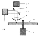
図5に本発明の光学情報記録媒体の記録再生を行う記録再生装置の最小限必要な装置構成の一例の概略図を示す。レーザダイオード17を出たレーザ光5は、ハーフミラー18及び対物レンズ6を通じて、モーター19によって回転されている光学情報記録媒体20上にフォーカシングされ、その反射光をフォトディテクター21に入射させて信号を検出する。
FIG. 5 shows a schematic diagram of an example of the minimum necessary apparatus configuration of a recording / reproducing apparatus for recording / reproducing the optical information recording medium of the present invention. The
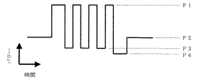
情報信号の記録を行う際には、レーザ光5の強度を複数のパワーレベル間で変調する。レーザ強度を変調するには、半導体レーザの駆動電流を変調して行うのが良く、あるいは電気光学変調器、音響光学変調器等の手段を用いることも可能である。マークを形成する部分に対しては、ピークパワーP1の単一矩形パルスでもよいが、特に長いマークを形成する場合は、過剰な熱を省き、マーク幅を均一にする目的で、図6に示すようにピークパワーP1及びボトムパワーP3(但し、P1>P3)との間で変調された複数のパルスの列からなる記録パルス列を用いる。また、最後尾のパルスの後に冷却パワーP4の冷却区間を設けても良い。マークを形成しない部分に対しては、バイアスパワーP2(但し、P1>P2)で一定に保つ。
When recording an information signal, the intensity of the
ここで、記録するマークの長さ、さらにはその前後のスペースの長さ等の各パターンによってマークエッジ位置に不揃いが生じ、ジッタ増大の原因となることがある。本発明の光学情報記録媒体の記録再生方法では、これを防止し、ジッタを改善するために、上記パルス列の各パルスの位置または長さをパターン毎にエッジ位置が揃うように必要に応じて調整し、補償することもできる。 Here, each pattern such as the length of the mark to be recorded and the length of the space before and after the mark causes irregularities in the mark edge position, which may cause an increase in jitter. In the recording / reproducing method of the optical information recording medium of the present invention, in order to prevent this and improve jitter, the position or length of each pulse of the pulse train is adjusted as necessary so that the edge position is aligned for each pattern. Can also be compensated.
以下、実施例により本発明をさらに具体的に説明するが、以下の実施例は本発明を限定するものではない。
保護基板を作製するための原盤は、以下の方法により作製したものを用いた。
カッティング工程において、原盤の半径45mmを境にして外周側では、原盤に対してカッティング用のレーザ光を原盤の中心から0度から30度の範囲で傾斜させて入射させることにより、案内溝の外周側の傾斜角が内周側の傾斜角よりも0度から30度小さい原盤を作製した。
EXAMPLES Hereinafter, although an Example demonstrates this invention further more concretely, a following example does not limit this invention.
As the master for producing the protective substrate, one produced by the following method was used.
In the cutting process, on the outer peripheral side of the master disk with a radius of 45 mm as the boundary, the cutting laser beam is incident on the master disk at an angle of 0 to 30 degrees from the center of the master disk. A master having an inclination angle on the side smaller than the inclination angle on the inner peripheral side by 0 to 30 degrees was produced.
保護基板としては、ポリカーボネート樹脂からなり、直径約12cm、厚さ約1.1mm、案内溝ピッチ0.32μm、案内溝深さ約20nmのものを用いた。
案内溝が形成された保護基板の表面上に、第2情報層として、Ag98Pd1Cu1からなる膜厚80nmの反射膜、Alからなる膜厚10nmの反射膜、(ZnS)80(SiO2)20からなる膜厚15nmの上側誘電体膜、Cからなる膜厚2nmの上側界面膜、Ge45Sb5Te55からなる膜厚10nmの記録膜、(ZrO2)25(SiO2)25(Cr2O3)50からなる膜厚5nmの下側界面膜、(ZnS)80(SiO2)20からなる膜厚55nmの下側誘電体膜の各層をスパッタリング法によりこの順に積層した。
A protective substrate made of polycarbonate resin having a diameter of about 12 cm, a thickness of about 1.1 mm, a guide groove pitch of 0.32 μm, and a guide groove depth of about 20 nm was used.
On the surface of the protective substrate on which the guide groove is formed, as the second information layer, a reflective film made of Ag 98 Pd 1 Cu 1 having a thickness of 80 nm, a reflective film made of Al having a thickness of 10 nm, (ZnS) 80 (SiO 2 2 ) 15 nm thick upper dielectric film made of 20 ; 2 nm thick upper interface film made of C; 10 nm thick recording film made of Ge 45 Sb 5 Te 55 ; (ZrO 2 ) 25 (SiO 2 ) 25 Each layer of a lower interface film made of (Cr 2 O 3 ) 50 having a thickness of 5 nm and a lower dielectric film made of (ZnS) 80 (SiO 2 ) 20 having a thickness of 55 nm was laminated in this order by sputtering.
この第2情報層の表面上に、紫外線硬化性樹脂を用いて2P法により保護基板と同じ溝パターンを転写し、厚さ25μmの分離層を形成した。 On the surface of the second information layer, the same groove pattern as that of the protective substrate was transferred by the 2P method using an ultraviolet curable resin to form a separation layer having a thickness of 25 μm.
この分離層の表面上に、第1情報層として、TiO2からなる膜厚23nmの透過率調整層、Ag98Pd1Cu1からなる膜厚10nmの反射膜、(ZrO2)35(SiO2)35(Cr2O3)30からなる膜厚13nmの上側誘電体膜、(ZrO2)50(Cr2O3)50Cからなる膜厚3nmの上側界面膜、Ge45Sb5Te55からなる膜厚6nmの記録膜、(ZrO2)50(Cr2O3)50からなる膜厚5nmの下側界面膜、(ZnS)80(SiO2)20からなる膜厚36nmの下側誘電体膜の各層をスパッタリング法によりこの順に積層した。 On the surface of this separation layer, as a first information layer, a transmittance adjusting layer made of TiO 2 with a thickness of 23 nm, a reflective film made of Ag 98 Pd 1 Cu 1 with a thickness of 10 nm, (ZrO 2 ) 35 (SiO 2 ) A 13 nm thick upper dielectric film made of 35 (Cr 2 O 3 ) 30, a 3 nm thick upper interface film made of (ZrO 2 ) 50 (Cr 2 O 3 ) 50 C, and Ge 45 Sb 5 Te 55 6 nm thick recording film, (ZrO 2 ) 50 (Cr 2 O 3 ) 50 thick film lower interface film, (ZnS) 80 (SiO 2 ) 20 thick film lower dielectric film Each layer of the film was laminated in this order by a sputtering method.
この第1情報層の表面上に、ポリカーボネートのシートを紫外線硬化樹脂を用いて貼り合わせ、厚さ75μmの透明基板とした。そして、このディスクを回転させながら透明基板側からレーザ光でアニールすることにより各情報層の記録膜全面を初期化した。 On the surface of the first information layer, a polycarbonate sheet was bonded using an ultraviolet curable resin to obtain a transparent substrate having a thickness of 75 μm. Then, the entire recording film of each information layer was initialized by annealing with a laser beam from the transparent substrate side while rotating the disk.
なお、各層の成膜はいずれも直径200mm、厚さ6mm程度のターゲットを用いた。透過率調整膜、誘電体膜及び界面膜はRF電源で2kW、反射膜はDC電源で2kW、記録膜はDC電源で500Wで成膜した。記録膜はAr−N2混合ガス(N2分圧3%)を、その他の膜はArガスのみをスパッタガスとして、いずれもガス圧0.2Paに保って成膜した。 Each layer was formed using a target having a diameter of about 200 mm and a thickness of about 6 mm. The transmittance adjusting film, the dielectric film, and the interface film were formed with an RF power source of 2 kW, the reflective film with a DC power source of 2 kW, and the recording film with a DC power source of 500 W. The recording film was formed using an Ar—N 2 mixed gas (N 2 partial pressure of 3%), and the other films were formed using only Ar gas as a sputtering gas, with the gas pressure maintained at 0.2 Pa.
ここで、各層を成膜する上で案内溝の両側の傾斜面における膜厚差を制御するために、ディスクの半径の半分の値である30mmより大きい半径45mmを境にして、それから外側の領域と内側の領域において、案内溝の外周側の傾斜角を内周側の傾斜角よりも小さくするように案内溝の傾斜角を変えている。表1に示すように、ディスクAからGは外側の領域における傾斜角度差を0度〜30度の範囲で変化させたものである。なお、内側の領域における傾斜角度差は外側の領域における傾斜角度差よりも小さくなるように設定した。 Here, in order to control the film thickness difference between the inclined surfaces on both sides of the guide groove when forming each layer, the outer region is set with a radius 45 mm larger than 30 mm, which is half the radius of the disk, as a boundary. In the inner region, the inclination angle of the guide groove is changed so that the inclination angle on the outer peripheral side of the guide groove is smaller than the inclination angle on the inner peripheral side. As shown in Table 1, the discs A to G are obtained by changing the inclination angle difference in the outer region in the range of 0 degrees to 30 degrees. The inclination angle difference in the inner region was set to be smaller than the inclination angle difference in the outer region.
各ディスクの半径55mmの位置において、その断面を透過電子顕微鏡で観察し、案内溝の内周側及び外周側の傾斜角の差と、両傾斜面における第1情報層の膜厚d1及びd2を測定した。また、ディスクを内周領域(半径が25mm以下の領域)及び中周領域(半径が25より大きく40mm以下の領域)、そして外周領域(半径が40mmより大きい領域)に3分割して、以下に示す方法によりノイズレベルを測定した。 In the position of the radius 55mm of the disk, the cross section thereof was observed with a transmission electron microscope, the difference in inclination angle of the inner and outer circumferential sides of the guide groove, the thickness d 1 and d of the first information layer in the both inclined surfaces 2 was measured. In addition, the disk is divided into an inner peripheral area (an area having a radius of 25 mm or less), an intermediate peripheral area (an area having a radius greater than 25 mm and less than 40 mm), and an outer peripheral area (an area having a radius greater than 40 mm). The noise level was measured by the method shown.
上記各ディスクのグルーブ、すなわち溝及び溝間のうちレーザ光入射側から見て手前に凸になっている部分に対し、波長405nm・レンズ開口数0.85の光学系を用い、線速5m/sで回転させながら、(1−7)変調方式でマーク長0.154μmの2T信号及びマーク長0.693μmの9T信号を記録した。 The optical system having a wavelength of 405 nm and a numerical aperture of the lens of 0.85 is used for the groove of each disk, that is, between the grooves and between the grooves, which is convex toward the front when viewed from the laser beam incident side. While rotating at s, a 2T signal having a mark length of 0.154 μm and a 9T signal having a mark length of 0.693 μm were recorded by the (1-7) modulation method.
信号を記録する際には図6に示すパルス波形を用い、2T信号の場合はパルス幅は13.7nsの単一パルス、9T信号の場合は20.5nsの先頭パルスとこれに続く幅及び間隔ともに6.9nsの7個のサブパルスからなるパルス列とした。P3及びP4は0mW、再生パワーはすべて0.7mWとした。 When recording a signal, the pulse waveform shown in FIG. 6 is used. In the case of 2T signal, the pulse width is a single pulse of 13.7 ns, and in the case of 9T signal, the head pulse of 20.5 ns is followed by the following width and interval. Both pulse trains consisted of 7 sub-pulses of 6.9 ns. P3 and P4 were 0 mW, and the reproduction power was all 0.7 mW.
この条件で、未記録のトラックに2T信号及び9T信号を交互に合計11回記録を行い、2T信号が記録された状態でC/N比をスペクトラムアナライザーで測定した。さらに、その上に9T信号を記録し、消去率、すなわち2T信号振幅の減衰比を同じくスペクトラムアナライザーで測定した。P1及びP2を任意に変化させて測定し、P1は振幅が最大値より3dB低くなるパワーの1.3倍の値、P2は消去率が25dBを超えるパワー範囲の中心値を設定パワーとした。いずれのディスクも設定パワーは第1情報層ではP1が10mW、P2が4.0mW、第2情報層ではP1が10mW、P2が3.5mWであった。各ディスクの設定パワーにおけるノイズレベルを表1に示す。なお、表1には外周領域におけるノイズレベルのみを示したが、内周領域及び中周領域においても外周領域と同様のノイズレベルであった。 Under these conditions, 2T signals and 9T signals were alternately recorded a total of 11 times on unrecorded tracks, and the C / N ratio was measured with a spectrum analyzer in the state where the 2T signals were recorded. Further, a 9T signal was recorded thereon, and the erasure rate, that is, the attenuation ratio of the 2T signal amplitude was measured with a spectrum analyzer. Measurement was performed by arbitrarily changing P1 and P2. P1 was set to 1.3 times the power at which the amplitude was 3 dB lower than the maximum value, and P2 was set to the center value of the power range in which the erasure rate exceeds 25 dB. In both discs, the set power was 10 mW for P1 and 4.0 mW for P2 in the first information layer, 10 mW for P1 and 3.5 mW for P2 in the second information layer. Table 1 shows the noise level at the set power of each disk. Table 1 shows only the noise level in the outer peripheral region, but the noise level in the inner peripheral region and the intermediate peripheral region is the same as that in the outer peripheral region.

表1から明らかなように、傾斜角度差が20度以上では、外周領域において、d2とd1の比が1に近づき、かつ良好なノイズレベルが得られた。また、内周領域と中周領域では、両方の傾斜角度を揃えると、d2とd1の比が1に近づく傾向が認められた。特に、内周領域では、傾斜角度差を10度以下とすることにより、d2/d1の値が1±0.05の範囲内で安定して得られた。 As is apparent from Table 1, when the difference in tilt angle was 20 degrees or more, the ratio of d 2 and d 1 approached 1 and a good noise level was obtained in the outer peripheral region. In addition, in the inner peripheral region and the intermediate peripheral region, it was recognized that the ratio of d 2 and d 1 tends to approach 1 when both the inclination angles are aligned. In particular, in the inner peripheral region, the value of d 2 / d 1 was stably obtained within the range of 1 ± 0.05 by setting the difference in inclination angle to 10 degrees or less.
以上説明したように、書換型の半透明な情報層を有する光情報記録媒体において、案内溝の斜面形状を制御することで、外周領域においても、ノイズレベルの低い良好な信号品質が実現可能である。 As described above, in an optical information recording medium having a rewritable translucent information layer, good signal quality with a low noise level can be realized even in the outer peripheral region by controlling the slope shape of the guide groove. is there.
本発明に係る光学情報記録媒体は、画像情報等の大容量の情報を記録・再生する用途において特に有用である。 The optical information recording medium according to the present invention is particularly useful in applications for recording / reproducing large-capacity information such as image information.
1 透明基板、2 第1情報層、3 保護基板、4 溝、5 レーザ光、6 対物レンズ、7 分離層、8 第2情報層、9 第n情報層、10 下側誘電体膜、11 下側界面膜、12 記録膜、13 上側界面膜、14 上側誘電体膜、15 反射膜、16 透過率調整膜、17 レーザダイオード、18 ハーフミラー、19 モーター、20 光学的情報記録媒体、21 フォトディテクター、41 底面、42 傾斜面。
DESCRIPTION OF
Claims (8)
前記レーザ光照射面側から順に、透明基板と、前記情報層と、案内溝を有する保護基板とを含み、
少なくとも、前記情報層のうちレーザ光照射面側にある第1情報層が、前記案内溝を有する保護基板の上に気相薄膜堆積法により半透明に形成され、
前記第1情報層の案内溝における内周側と外周側の傾斜面が、前記案内溝のレーザ光照射面側にある底面に対し、それぞれ傾斜角αとβを有し、
前記保護基板の半径をrとしたとき、前記保護基板の中心から距離3r/4より小さい半径方向に前記傾斜角αとβが異なる第1の非対称領域と、前記保護基板の中心から距離3r/4より大きい半径方向に前記傾斜角αとβが異なる第2の非対称領域とを有し、
前記第1の非対称領域においてはα−β≦10度であり、前記第2の非対称領域においてはα−β≧20度の関係を有し、かつ
前記第1情報層の内周側傾斜面における膜厚をd 1 、前記第1情報層の外周側傾斜面における膜厚をd 2 とした場合、d 2 /d 1 が1±0.05の範囲にある、光学情報記録媒体。An optical information recording medium comprising one or more information layers including a recording layer for recording / reproducing an information signal by laser light irradiation,
In order from the laser light irradiation surface side, including a transparent substrate, the information layer, and a protective substrate having a guide groove ,
At least the first information layer on the laser light irradiation surface side of the information layer is formed translucently on the protective substrate having the guide groove by vapor phase thin film deposition,
The inclined surfaces on the inner peripheral side and the outer peripheral side in the guide groove of the first information layer have inclination angles α and β with respect to the bottom surface on the laser light irradiation surface side of the guide groove, respectively.
When the radius of the protective substrate is r, a first asymmetric region in which the inclination angles α and β are different in a radial direction smaller than a distance 3r / 4 from the center of the protective substrate, and a distance 3r / from the center of the protective substrate. A second asymmetric region having different inclination angles α and β in a radial direction greater than 4,
Wherein in the first asymmetric region is α-β ≦ 10 degrees, in the second asymmetric regions have a α-β ≧ 20 ° relationship, and
D 1 film thickness on the inner circumferential side inclined surface of the first information layer, if the thickness of the outer peripheral-side inclined surface of the first information layer was d 2, d 2 / d 1 is 1 ± 0.05 Optical information recording medium in range .
前記レーザ光照射面側から順に、前記複数の情報層が、前記第1情報層、第2情報層、・・・、第n情報層(n≧3)で構成され、かつ前記複数の情報層は前記案内溝を有する保護基板の上に気相薄膜堆積法により半透明に形成される、請求項1記載の光学情報記録媒体。An optical information recording medium comprising a plurality of information layers,
The plurality of information layers are composed of the first information layer, the second information layer,..., The nth information layer (n ≧ 3) in order from the laser light irradiation surface side , and the plurality of information layers. the optical information recording medium of which the gas phase thin film deposition method on the protective substrate having the guide groove Ru formed translucent, according to claim 1.
前記光学情報記録媒体は、
前記レーザ光照射面側から順に、透明基板と、前記情報層と、案内溝を有する保護基板とを含み、
少なくとも、前記情報層のうちレーザ光照射面側にある第1情報層が、前記案内溝を有する保護基板の上に気相薄膜堆積法により半透明に形成され、
前記第1情報層の案内溝における内周側と外周側の傾斜面が、前記案内溝のレーザ光照射面側にある底面に対し、それぞれ傾斜角αとβを有し、
前記保護基板の半径をrとしたとき、前記保護基板の中心から距離3r/4より小さい半径方向に前記傾斜角αとβが異なる第1の非対称領域と、前記保護基板の中心から距離3r/4より大きい半径方向に前記傾斜角αとβが異なる第2の非対称領域とを有し、
前記第1の非対称領域においてはα−β≦10度であり、前記第2の非対称領域においてはα−β≧20度の関係を有し、かつ
前記第1情報層の内周側傾斜面における膜厚をd 1 、前記第1情報層の外周側傾斜面における膜厚をd 2 とした場合、d 2 /d 1 が1±0.05の範囲にある、光学情報記録媒体の製造方法。A method for producing an optical information recording medium comprising one or more information layers including a recording layer for recording / reproducing an information signal by irradiation with a laser beam,
The optical information recording medium is
In order from the laser light irradiation surface side, including a transparent substrate, the information layer, and a protective substrate having a guide groove ,
At least the first information layer on the laser light irradiation surface side of the information layer is formed translucently on the protective substrate having the guide groove by vapor phase thin film deposition,
The inclined surfaces on the inner peripheral side and the outer peripheral side in the guide groove of the first information layer have inclination angles α and β with respect to the bottom surface on the laser light irradiation surface side of the guide groove, respectively.
When the radius of the protective substrate is r, a first asymmetric region in which the inclination angles α and β are different in a radial direction smaller than a distance 3r / 4 from the center of the protective substrate, and a distance 3r / from the center of the protective substrate. A second asymmetric region having different inclination angles α and β in a radial direction greater than 4,
Wherein in the first asymmetric region is α-β ≦ 10 degrees, in the second asymmetric regions have a α-β ≧ 20 ° relationship, and
D 1 film thickness on the inner circumferential side inclined surface of the first information layer, if the thickness of the outer peripheral-side inclined surface of the first information layer was d 2, d 2 / d 1 is 1 ± 0.05 The manufacturing method of the optical information recording medium in the range .
前記集光レンズに入射するレーザ光の光軸を傾斜させて前記レジスト層をカッティングする、請求項6記載の光学情報記録媒体の製造方法。A resist layer is formed on a master substrate, a laser beam is collected by a condenser lens, the resist layer is cut to form a mask pattern, and a spiral or concentric guide groove is formed by etching to form the master disc When making
The method for manufacturing an optical information recording medium according to claim 6 , wherein the resist layer is cut by tilting an optical axis of laser light incident on the condenser lens.
集光された2つのレーザ光を用いてレジスト層をカッティングする、請求項6記載の光学情報記録媒体の製造方法。A resist layer is formed on a master substrate, a laser beam is collected by a condenser lens, the resist layer is cut to form a mask pattern, and a spiral or concentric guide groove is formed by etching to form the master disc When making
The method for producing an optical information recording medium according to claim 6 , wherein the resist layer is cut using two focused laser beams.
Applications Claiming Priority (3)
| Application Number | Priority Date | Filing Date | Title |
|---|---|---|---|
| JP2003288787 | 2003-08-07 | ||
| JP2003288787 | 2003-08-07 | ||
| PCT/JP2004/011239 WO2005015555A1 (en) | 2003-08-07 | 2004-08-05 | Optical information recording medium and manufacturing method thereof |
Publications (2)
| Publication Number | Publication Date |
|---|---|
| JPWO2005015555A1 JPWO2005015555A1 (en) | 2007-09-27 |
| JP4490918B2 true JP4490918B2 (en) | 2010-06-30 |
Family
ID=34131529
Family Applications (1)
| Application Number | Title | Priority Date | Filing Date |
|---|---|---|---|
| JP2005512948A Expired - Fee Related JP4490918B2 (en) | 2003-08-07 | 2004-08-05 | Optical information recording medium and manufacturing method thereof |
Country Status (6)
| Country | Link |
|---|---|
| US (1) | US7540006B2 (en) |
| EP (1) | EP1655728A4 (en) |
| JP (1) | JP4490918B2 (en) |
| KR (1) | KR20060052819A (en) |
| CN (1) | CN1833280A (en) |
| WO (1) | WO2005015555A1 (en) |
Families Citing this family (6)
| Publication number | Priority date | Publication date | Assignee | Title |
|---|---|---|---|---|
| KR101049985B1 (en) * | 2003-08-07 | 2011-07-19 | 파나소닉 주식회사 | Optical information recording medium, its manufacturing method, manufacturing apparatus, recording / reproducing method, and recording / reproducing apparatus |
| FR2882851B1 (en) * | 2005-03-03 | 2009-05-22 | Commissariat Energie Atomique | OPTICAL DATA RECORDING MEDIUM COMPRISING A THIN ALLOY OF TIN AND TENSILE ALLOY |
| JP2009181662A (en) * | 2008-01-31 | 2009-08-13 | Toshiba Corp | Master recording system and recording method |
| JP2015060891A (en) | 2013-09-17 | 2015-03-30 | 株式会社東芝 | Memory device |
| BR112020000011A2 (en) | 2017-07-11 | 2020-07-21 | Qualicaps Co., Ltd. | enteric hard capsule |
| WO2019245031A1 (en) | 2018-06-22 | 2019-12-26 | クオリカプス株式会社 | Enteric hard capsule |
Family Cites Families (17)
| Publication number | Priority date | Publication date | Assignee | Title |
|---|---|---|---|---|
| JPH01315044A (en) * | 1988-06-14 | 1989-12-20 | Canon Inc | Substrate for information recording medium and master disk for production thereof |
| US5283690A (en) * | 1989-04-04 | 1994-02-01 | Sharp Kabushiki Kaisha | Optical diffraction grating element |
| US5946288A (en) * | 1995-03-31 | 1999-08-31 | Nec Corporation | Optical recording medium having recording pits of different shapes |
| JPH09320117A (en) * | 1996-05-28 | 1997-12-12 | Pioneer Electron Corp | Optical disk |
| JPH09320100A (en) | 1996-05-28 | 1997-12-12 | Matsushita Electric Ind Co Ltd | Recording apparatus for original optical disk |
| JPH10154351A (en) | 1996-09-27 | 1998-06-09 | Sony Corp | Optical recording medium and its production |
| JPH10275369A (en) * | 1997-01-31 | 1998-10-13 | Canon Inc | Manufacture of information recording medium and information recording medium made by the same |
| US6287660B1 (en) * | 1997-04-24 | 2001-09-11 | Matsushita Electric Industrial Co., Ltd. | Optical recording medium and its substrate |
| JP3209948B2 (en) * | 1997-08-27 | 2001-09-17 | 株式会社リコー | Optical information recording medium and master disc exposure method |
| JPH1196601A (en) * | 1997-09-17 | 1999-04-09 | Nikon Corp | Optical disk and its production |
| EP0957477A3 (en) * | 1998-05-15 | 2003-11-05 | Matsushita Electric Industrial Co., Ltd. | Optical information recording medium, recording and reproducing method therefor and optical information recording and reproduction apparatus |
| JP3250989B2 (en) | 1998-05-15 | 2002-01-28 | 松下電器産業株式会社 | Optical information recording medium, recording / reproducing method thereof, manufacturing method thereof, and optical information recording / reproducing apparatus |
| JP2000322773A (en) * | 1999-03-09 | 2000-11-24 | Hitachi Maxell Ltd | Optical disk |
| JP2000322774A (en) * | 1999-03-09 | 2000-11-24 | Hitachi Maxell Ltd | Optical disk |
| US7120097B1 (en) | 2000-09-15 | 2006-10-10 | Eastman Kodak Company | System for making a photoresist master for a hybrid optical recording disc |
| US7315508B2 (en) | 2000-10-03 | 2008-01-01 | Matsushita Electric Industrial Co., Ltd. | Multi-layer optical disk and method of producing multi-layer optical disk |
| JP2002117588A (en) * | 2000-10-04 | 2002-04-19 | Nikon Corp | Optical disk and stamper |
-
2004
- 2004-08-05 JP JP2005512948A patent/JP4490918B2/en not_active Expired - Fee Related
- 2004-08-05 WO PCT/JP2004/011239 patent/WO2005015555A1/en active Application Filing
- 2004-08-05 EP EP04771266A patent/EP1655728A4/en not_active Withdrawn
- 2004-08-05 KR KR1020067000981A patent/KR20060052819A/en not_active Application Discontinuation
- 2004-08-05 US US10/567,356 patent/US7540006B2/en not_active Expired - Fee Related
- 2004-08-05 CN CNA2004800226799A patent/CN1833280A/en active Pending
Also Published As
| Publication number | Publication date |
|---|---|
| CN1833280A (en) | 2006-09-13 |
| JPWO2005015555A1 (en) | 2007-09-27 |
| EP1655728A1 (en) | 2006-05-10 |
| KR20060052819A (en) | 2006-05-19 |
| US7540006B2 (en) | 2009-05-26 |
| WO2005015555A1 (en) | 2005-02-17 |
| US20060146685A1 (en) | 2006-07-06 |
| EP1655728A4 (en) | 2008-04-30 |
Similar Documents
| Publication | Publication Date | Title |
|---|---|---|
| US6768710B2 (en) | Optical information recording medium, method for producing the same, and method and apparatus for recording information thereon | |
| US6610380B2 (en) | Optical information recording medium, manufacturing method, recording and reproduction method, and recording/reproduction device | |
| US7442424B2 (en) | Information storage medium having super resolution structure and apparatus for recording to and/or reproducing from the same | |
| JP2002133712A (en) | Optical information recording medium, its manufacturing method, recording/reproducing method and recording/ reproducing device | |
| US7008681B2 (en) | Optical information recording medium and manufacturing method and recording/reproducing method for the same | |
| US6764736B2 (en) | Optical information recording medium and recording method using the same | |
| JP2006315242A (en) | Phase change type optical information recording medium | |
| JP2005122872A (en) | Two-layer phase-change type information recording medium and its recording and reproducing method | |
| JP4490918B2 (en) | Optical information recording medium and manufacturing method thereof | |
| US7074471B2 (en) | Optical information recording medium, method for producing the medium, and method and apparatus for recording information using the medium | |
| JPWO2004032130A1 (en) | Optical information recording medium and manufacturing method thereof | |
| JP3752177B2 (en) | Write-once optical information recording medium and manufacturing method thereof | |
| JP4141993B2 (en) | Optical information recording medium | |
| JP2001273673A (en) | Optical recording medium and method for producing the same | |
| JP5437793B2 (en) | Information recording medium and manufacturing method thereof | |
| JP4468951B2 (en) | Optical information recording medium and optical information recording / reproducing system | |
| JP3908682B2 (en) | Optical information recording medium, manufacturing method thereof, and recording / reproducing method thereof | |
| JP4542922B2 (en) | Optical information recording medium and manufacturing method thereof | |
| JPWO2006025162A1 (en) | Optical information recording medium and method for manufacturing the same | |
| JP2004311011A (en) | Optical information recording medium, its manufacturing method, and recording method and recording device of information using the medium | |
| JP2003091873A (en) | Optical information recording medium and recording method using the same | |
| JP4719172B2 (en) | Multilayer optical recording medium | |
| JP2004303350A (en) | Information recording medium, and method and device of recording information to the medium | |
| JP2006018982A (en) | Recording method for phase change information recording medium and its recording device | |
| JPH1021583A (en) | Optical recording medium, and recording and reproducing method |
Legal Events
| Date | Code | Title | Description |
|---|---|---|---|
| A621 | Written request for application examination |
Free format text: JAPANESE INTERMEDIATE CODE: A621 Effective date: 20070704 |
|
| A521 | Request for written amendment filed |
Free format text: JAPANESE INTERMEDIATE CODE: A523 Effective date: 20070731 |
|
| A131 | Notification of reasons for refusal |
Free format text: JAPANESE INTERMEDIATE CODE: A131 Effective date: 20090901 |
|
| A521 | Request for written amendment filed |
Free format text: JAPANESE INTERMEDIATE CODE: A523 Effective date: 20091026 |
|
| A131 | Notification of reasons for refusal |
Free format text: JAPANESE INTERMEDIATE CODE: A131 Effective date: 20091208 |
|
| RD03 | Notification of appointment of power of attorney |
Free format text: JAPANESE INTERMEDIATE CODE: A7423 Effective date: 20100119 |
|
| A521 | Request for written amendment filed |
Free format text: JAPANESE INTERMEDIATE CODE: A523 Effective date: 20100127 |
|
| TRDD | Decision of grant or rejection written | ||
| A01 | Written decision to grant a patent or to grant a registration (utility model) |
Free format text: JAPANESE INTERMEDIATE CODE: A01 Effective date: 20100309 |
|
| A01 | Written decision to grant a patent or to grant a registration (utility model) |
Free format text: JAPANESE INTERMEDIATE CODE: A01 |
|
| A61 | First payment of annual fees (during grant procedure) |
Free format text: JAPANESE INTERMEDIATE CODE: A61 Effective date: 20100402 |
|
| FPAY | Renewal fee payment (event date is renewal date of database) |
Free format text: PAYMENT UNTIL: 20130409 Year of fee payment: 3 |
|
| R150 | Certificate of patent or registration of utility model |
Free format text: JAPANESE INTERMEDIATE CODE: R150 |
|
| LAPS | Cancellation because of no payment of annual fees |