JP4490912B2 - System and method of use for vaporizing liquid fuel for combustion - Google Patents
System and method of use for vaporizing liquid fuel for combustion Download PDFInfo
- Publication number
- JP4490912B2 JP4490912B2 JP2005501180A JP2005501180A JP4490912B2 JP 4490912 B2 JP4490912 B2 JP 4490912B2 JP 2005501180 A JP2005501180 A JP 2005501180A JP 2005501180 A JP2005501180 A JP 2005501180A JP 4490912 B2 JP4490912 B2 JP 4490912B2
- Authority
- JP
- Japan
- Prior art keywords
- gas
- fuel
- combustor
- oxygen
- stream
- Prior art date
- Legal status (The legal status is an assumption and is not a legal conclusion. Google has not performed a legal analysis and makes no representation as to the accuracy of the status listed.)
- Expired - Lifetime
Links
- 239000000446 fuel Substances 0.000 title claims description 195
- 238000002485 combustion reaction Methods 0.000 title claims description 93
- 239000007788 liquid Substances 0.000 title claims description 92
- 230000008016 vaporization Effects 0.000 title claims description 47
- 238000000034 method Methods 0.000 title claims description 45
- 239000007789 gas Substances 0.000 claims description 143
- VNWKTOKETHGBQD-UHFFFAOYSA-N methane Chemical compound C VNWKTOKETHGBQD-UHFFFAOYSA-N 0.000 claims description 112
- 229910052760 oxygen Inorganic materials 0.000 claims description 105
- 239000001301 oxygen Substances 0.000 claims description 102
- QVGXLLKOCUKJST-UHFFFAOYSA-N atomic oxygen Chemical compound [O] QVGXLLKOCUKJST-UHFFFAOYSA-N 0.000 claims description 101
- 239000003570 air Substances 0.000 claims description 63
- 239000003345 natural gas Substances 0.000 claims description 46
- 239000000203 mixture Substances 0.000 claims description 41
- 238000009834 vaporization Methods 0.000 claims description 41
- 239000002737 fuel gas Substances 0.000 claims description 31
- MYMOFIZGZYHOMD-UHFFFAOYSA-N Dioxygen Chemical compound O=O MYMOFIZGZYHOMD-UHFFFAOYSA-N 0.000 claims description 29
- 229910001882 dioxygen Inorganic materials 0.000 claims description 28
- 229930195733 hydrocarbon Natural products 0.000 claims description 27
- 150000002430 hydrocarbons Chemical class 0.000 claims description 27
- 239000004215 Carbon black (E152) Substances 0.000 claims description 25
- 239000006200 vaporizer Substances 0.000 claims description 17
- OFBQJSOFQDEBGM-UHFFFAOYSA-N n-pentane Natural products CCCCC OFBQJSOFQDEBGM-UHFFFAOYSA-N 0.000 claims description 16
- 238000002156 mixing Methods 0.000 claims description 14
- 238000000926 separation method Methods 0.000 claims description 12
- ATUOYWHBWRKTHZ-UHFFFAOYSA-N Propane Chemical compound CCC ATUOYWHBWRKTHZ-UHFFFAOYSA-N 0.000 claims description 9
- 239000012080 ambient air Substances 0.000 claims description 6
- 238000010438 heat treatment Methods 0.000 claims description 6
- 239000001273 butane Substances 0.000 claims description 4
- 125000004432 carbon atom Chemical group C* 0.000 claims description 4
- 239000002283 diesel fuel Substances 0.000 claims description 4
- 239000003502 gasoline Substances 0.000 claims description 4
- IJDNQMDRQITEOD-UHFFFAOYSA-N n-butane Chemical compound CCCC IJDNQMDRQITEOD-UHFFFAOYSA-N 0.000 claims description 4
- 239000001294 propane Substances 0.000 claims description 4
- 238000001179 sorption measurement Methods 0.000 claims description 4
- 239000010808 liquid waste Substances 0.000 claims description 3
- 230000006835 compression Effects 0.000 claims description 2
- 238000007906 compression Methods 0.000 claims description 2
- 239000003921 oil Substances 0.000 claims description 2
- 238000011144 upstream manufacturing Methods 0.000 claims 5
- UFHFLCQGNIYNRP-UHFFFAOYSA-N Hydrogen Chemical compound [H][H] UFHFLCQGNIYNRP-UHFFFAOYSA-N 0.000 claims 1
- 238000003763 carbonization Methods 0.000 claims 1
- 239000000295 fuel oil Substances 0.000 claims 1
- 238000009792 diffusion process Methods 0.000 description 18
- 238000010586 diagram Methods 0.000 description 13
- IJGRMHOSHXDMSA-UHFFFAOYSA-N Atomic nitrogen Chemical compound N#N IJGRMHOSHXDMSA-UHFFFAOYSA-N 0.000 description 12
- 239000003949 liquefied natural gas Substances 0.000 description 7
- 229910052757 nitrogen Inorganic materials 0.000 description 6
- 230000008569 process Effects 0.000 description 5
- 239000003344 environmental pollutant Substances 0.000 description 4
- 239000011261 inert gas Substances 0.000 description 4
- 231100000719 pollutant Toxicity 0.000 description 4
- 230000008901 benefit Effects 0.000 description 3
- 238000010790 dilution Methods 0.000 description 3
- 239000012895 dilution Substances 0.000 description 3
- 238000010248 power generation Methods 0.000 description 3
- 230000009467 reduction Effects 0.000 description 3
- 238000006243 chemical reaction Methods 0.000 description 2
- 230000003111 delayed effect Effects 0.000 description 2
- 238000007599 discharging Methods 0.000 description 2
- 230000004048 modification Effects 0.000 description 2
- 238000012986 modification Methods 0.000 description 2
- UGFAIRIUMAVXCW-UHFFFAOYSA-N Carbon monoxide Chemical compound [O+]#[C-] UGFAIRIUMAVXCW-UHFFFAOYSA-N 0.000 description 1
- OTMSDBZUPAUEDD-UHFFFAOYSA-N Ethane Chemical compound CC OTMSDBZUPAUEDD-UHFFFAOYSA-N 0.000 description 1
- VGGSQFUCUMXWEO-UHFFFAOYSA-N Ethene Chemical compound C=C VGGSQFUCUMXWEO-UHFFFAOYSA-N 0.000 description 1
- 239000005977 Ethylene Substances 0.000 description 1
- HSFWRNGVRCDJHI-UHFFFAOYSA-N alpha-acetylene Natural products C#C HSFWRNGVRCDJHI-UHFFFAOYSA-N 0.000 description 1
- 238000009835 boiling Methods 0.000 description 1
- 229910002091 carbon monoxide Inorganic materials 0.000 description 1
- 239000012159 carrier gas Substances 0.000 description 1
- 239000003245 coal Substances 0.000 description 1
- 239000000567 combustion gas Substances 0.000 description 1
- 238000009833 condensation Methods 0.000 description 1
- 230000005494 condensation Effects 0.000 description 1
- 239000000356 contaminant Substances 0.000 description 1
- 238000001816 cooling Methods 0.000 description 1
- 230000009977 dual effect Effects 0.000 description 1
- 230000007613 environmental effect Effects 0.000 description 1
- 125000002534 ethynyl group Chemical group [H]C#C* 0.000 description 1
- 238000002309 gasification Methods 0.000 description 1
- 230000008676 import Effects 0.000 description 1
- 230000003137 locomotive effect Effects 0.000 description 1
- 238000004519 manufacturing process Methods 0.000 description 1
- 239000000463 material Substances 0.000 description 1
- 230000007246 mechanism Effects 0.000 description 1
- 239000010743 number 2 fuel oil Substances 0.000 description 1
- 230000003647 oxidation Effects 0.000 description 1
- 238000007254 oxidation reaction Methods 0.000 description 1
- 230000001737 promoting effect Effects 0.000 description 1
- 230000002269 spontaneous effect Effects 0.000 description 1
- -1 that is Chemical compound 0.000 description 1
- 239000002699 waste material Substances 0.000 description 1
- XLYOFNOQVPJJNP-UHFFFAOYSA-N water Substances O XLYOFNOQVPJJNP-UHFFFAOYSA-N 0.000 description 1
Images


Classifications
-
- F—MECHANICAL ENGINEERING; LIGHTING; HEATING; WEAPONS; BLASTING
- F23—COMBUSTION APPARATUS; COMBUSTION PROCESSES
- F23D—BURNERS
- F23D11/00—Burners using a direct spraying action of liquid droplets or vaporised liquid into the combustion space
- F23D11/36—Details, e.g. burner cooling means, noise reduction means
- F23D11/44—Preheating devices; Vaporising devices
-
- F—MECHANICAL ENGINEERING; LIGHTING; HEATING; WEAPONS; BLASTING
- F02—COMBUSTION ENGINES; HOT-GAS OR COMBUSTION-PRODUCT ENGINE PLANTS
- F02B—INTERNAL-COMBUSTION PISTON ENGINES; COMBUSTION ENGINES IN GENERAL
- F02B43/00—Engines characterised by operating on gaseous fuels; Plants including such engines
- F02B43/08—Plants characterised by the engines using gaseous fuel generated in the plant from solid fuel, e.g. wood
-
- F—MECHANICAL ENGINEERING; LIGHTING; HEATING; WEAPONS; BLASTING
- F02—COMBUSTION ENGINES; HOT-GAS OR COMBUSTION-PRODUCT ENGINE PLANTS
- F02C—GAS-TURBINE PLANTS; AIR INTAKES FOR JET-PROPULSION PLANTS; CONTROLLING FUEL SUPPLY IN AIR-BREATHING JET-PROPULSION PLANTS
- F02C3/00—Gas-turbine plants characterised by the use of combustion products as the working fluid
- F02C3/20—Gas-turbine plants characterised by the use of combustion products as the working fluid using a special fuel, oxidant, or dilution fluid to generate the combustion products
- F02C3/24—Gas-turbine plants characterised by the use of combustion products as the working fluid using a special fuel, oxidant, or dilution fluid to generate the combustion products the fuel or oxidant being liquid at standard temperature and pressure
-
- F—MECHANICAL ENGINEERING; LIGHTING; HEATING; WEAPONS; BLASTING
- F02—COMBUSTION ENGINES; HOT-GAS OR COMBUSTION-PRODUCT ENGINE PLANTS
- F02C—GAS-TURBINE PLANTS; AIR INTAKES FOR JET-PROPULSION PLANTS; CONTROLLING FUEL SUPPLY IN AIR-BREATHING JET-PROPULSION PLANTS
- F02C3/00—Gas-turbine plants characterised by the use of combustion products as the working fluid
- F02C3/20—Gas-turbine plants characterised by the use of combustion products as the working fluid using a special fuel, oxidant, or dilution fluid to generate the combustion products
- F02C3/30—Adding water, steam or other fluids for influencing combustion, e.g. to obtain cleaner exhaust gases
-
- F—MECHANICAL ENGINEERING; LIGHTING; HEATING; WEAPONS; BLASTING
- F02—COMBUSTION ENGINES; HOT-GAS OR COMBUSTION-PRODUCT ENGINE PLANTS
- F02C—GAS-TURBINE PLANTS; AIR INTAKES FOR JET-PROPULSION PLANTS; CONTROLLING FUEL SUPPLY IN AIR-BREATHING JET-PROPULSION PLANTS
- F02C7/00—Features, components parts, details or accessories, not provided for in, or of interest apart form groups F02C1/00 - F02C6/00; Air intakes for jet-propulsion plants
- F02C7/22—Fuel supply systems
- F02C7/224—Heating fuel before feeding to the burner
-
- F—MECHANICAL ENGINEERING; LIGHTING; HEATING; WEAPONS; BLASTING
- F02—COMBUSTION ENGINES; HOT-GAS OR COMBUSTION-PRODUCT ENGINE PLANTS
- F02C—GAS-TURBINE PLANTS; AIR INTAKES FOR JET-PROPULSION PLANTS; CONTROLLING FUEL SUPPLY IN AIR-BREATHING JET-PROPULSION PLANTS
- F02C7/00—Features, components parts, details or accessories, not provided for in, or of interest apart form groups F02C1/00 - F02C6/00; Air intakes for jet-propulsion plants
- F02C7/22—Fuel supply systems
- F02C7/228—Dividing fuel between various burners
-
- F—MECHANICAL ENGINEERING; LIGHTING; HEATING; WEAPONS; BLASTING
- F02—COMBUSTION ENGINES; HOT-GAS OR COMBUSTION-PRODUCT ENGINE PLANTS
- F02G—HOT GAS OR COMBUSTION-PRODUCT POSITIVE-DISPLACEMENT ENGINE PLANTS; USE OF WASTE HEAT OF COMBUSTION ENGINES; NOT OTHERWISE PROVIDED FOR
- F02G3/00—Combustion-product positive-displacement engine plants
-
- F—MECHANICAL ENGINEERING; LIGHTING; HEATING; WEAPONS; BLASTING
- F03—MACHINES OR ENGINES FOR LIQUIDS; WIND, SPRING, OR WEIGHT MOTORS; PRODUCING MECHANICAL POWER OR A REACTIVE PROPULSIVE THRUST, NOT OTHERWISE PROVIDED FOR
- F03C—POSITIVE-DISPLACEMENT ENGINES DRIVEN BY LIQUIDS
- F03C1/00—Reciprocating-piston liquid engines
- F03C1/02—Reciprocating-piston liquid engines with multiple-cylinders, characterised by the number or arrangement of cylinders
- F03C1/06—Reciprocating-piston liquid engines with multiple-cylinders, characterised by the number or arrangement of cylinders with cylinder axes generally coaxial with, or parallel or inclined to, main shaft axis
-
- F—MECHANICAL ENGINEERING; LIGHTING; HEATING; WEAPONS; BLASTING
- F23—COMBUSTION APPARATUS; COMBUSTION PROCESSES
- F23C—METHODS OR APPARATUS FOR COMBUSTION USING FLUID FUEL OR SOLID FUEL SUSPENDED IN A CARRIER GAS OR AIR
- F23C9/00—Combustion apparatus characterised by arrangements for returning combustion products or flue gases to the combustion chamber
- F23C9/08—Combustion apparatus characterised by arrangements for returning combustion products or flue gases to the combustion chamber for reducing temperature in combustion chamber, e.g. for protecting walls of combustion chamber
-
- F—MECHANICAL ENGINEERING; LIGHTING; HEATING; WEAPONS; BLASTING
- F23—COMBUSTION APPARATUS; COMBUSTION PROCESSES
- F23K—FEEDING FUEL TO COMBUSTION APPARATUS
- F23K5/00—Feeding or distributing other fuel to combustion apparatus
- F23K5/02—Liquid fuel
- F23K5/08—Preparation of fuel
- F23K5/10—Mixing with other fluids
-
- F—MECHANICAL ENGINEERING; LIGHTING; HEATING; WEAPONS; BLASTING
- F23—COMBUSTION APPARATUS; COMBUSTION PROCESSES
- F23K—FEEDING FUEL TO COMBUSTION APPARATUS
- F23K5/00—Feeding or distributing other fuel to combustion apparatus
- F23K5/02—Liquid fuel
- F23K5/14—Details thereof
- F23K5/20—Preheating devices
-
- F—MECHANICAL ENGINEERING; LIGHTING; HEATING; WEAPONS; BLASTING
- F23—COMBUSTION APPARATUS; COMBUSTION PROCESSES
- F23K—FEEDING FUEL TO COMBUSTION APPARATUS
- F23K5/00—Feeding or distributing other fuel to combustion apparatus
- F23K5/02—Liquid fuel
- F23K5/14—Details thereof
- F23K5/22—Vaporising devices
-
- F—MECHANICAL ENGINEERING; LIGHTING; HEATING; WEAPONS; BLASTING
- F23—COMBUSTION APPARATUS; COMBUSTION PROCESSES
- F23L—SUPPLYING AIR OR NON-COMBUSTIBLE LIQUIDS OR GASES TO COMBUSTION APPARATUS IN GENERAL ; VALVES OR DAMPERS SPECIALLY ADAPTED FOR CONTROLLING AIR SUPPLY OR DRAUGHT IN COMBUSTION APPARATUS; INDUCING DRAUGHT IN COMBUSTION APPARATUS; TOPS FOR CHIMNEYS OR VENTILATING SHAFTS; TERMINALS FOR FLUES
- F23L7/00—Supplying non-combustible liquids or gases, other than air, to the fire, e.g. oxygen, steam
- F23L7/007—Supplying oxygen or oxygen-enriched air
-
- F—MECHANICAL ENGINEERING; LIGHTING; HEATING; WEAPONS; BLASTING
- F23—COMBUSTION APPARATUS; COMBUSTION PROCESSES
- F23R—GENERATING COMBUSTION PRODUCTS OF HIGH PRESSURE OR HIGH VELOCITY, e.g. GAS-TURBINE COMBUSTION CHAMBERS
- F23R3/00—Continuous combustion chambers using liquid or gaseous fuel
- F23R3/28—Continuous combustion chambers using liquid or gaseous fuel characterised by the fuel supply
- F23R3/30—Continuous combustion chambers using liquid or gaseous fuel characterised by the fuel supply comprising fuel prevapourising devices
-
- F—MECHANICAL ENGINEERING; LIGHTING; HEATING; WEAPONS; BLASTING
- F23—COMBUSTION APPARATUS; COMBUSTION PROCESSES
- F23C—METHODS OR APPARATUS FOR COMBUSTION USING FLUID FUEL OR SOLID FUEL SUSPENDED IN A CARRIER GAS OR AIR
- F23C2202/00—Fluegas recirculation
- F23C2202/20—Premixing fluegas with fuel
-
- F—MECHANICAL ENGINEERING; LIGHTING; HEATING; WEAPONS; BLASTING
- F23—COMBUSTION APPARATUS; COMBUSTION PROCESSES
- F23L—SUPPLYING AIR OR NON-COMBUSTIBLE LIQUIDS OR GASES TO COMBUSTION APPARATUS IN GENERAL ; VALVES OR DAMPERS SPECIALLY ADAPTED FOR CONTROLLING AIR SUPPLY OR DRAUGHT IN COMBUSTION APPARATUS; INDUCING DRAUGHT IN COMBUSTION APPARATUS; TOPS FOR CHIMNEYS OR VENTILATING SHAFTS; TERMINALS FOR FLUES
- F23L2900/00—Special arrangements for supplying or treating air or oxidant for combustion; Injecting inert gas, water or steam into the combustion chamber
- F23L2900/07003—Controlling the inert gas supply
-
- F—MECHANICAL ENGINEERING; LIGHTING; HEATING; WEAPONS; BLASTING
- F23—COMBUSTION APPARATUS; COMBUSTION PROCESSES
- F23L—SUPPLYING AIR OR NON-COMBUSTIBLE LIQUIDS OR GASES TO COMBUSTION APPARATUS IN GENERAL ; VALVES OR DAMPERS SPECIALLY ADAPTED FOR CONTROLLING AIR SUPPLY OR DRAUGHT IN COMBUSTION APPARATUS; INDUCING DRAUGHT IN COMBUSTION APPARATUS; TOPS FOR CHIMNEYS OR VENTILATING SHAFTS; TERMINALS FOR FLUES
- F23L2900/00—Special arrangements for supplying or treating air or oxidant for combustion; Injecting inert gas, water or steam into the combustion chamber
- F23L2900/07005—Injecting pure oxygen or oxygen enriched air
-
- F—MECHANICAL ENGINEERING; LIGHTING; HEATING; WEAPONS; BLASTING
- F23—COMBUSTION APPARATUS; COMBUSTION PROCESSES
- F23L—SUPPLYING AIR OR NON-COMBUSTIBLE LIQUIDS OR GASES TO COMBUSTION APPARATUS IN GENERAL ; VALVES OR DAMPERS SPECIALLY ADAPTED FOR CONTROLLING AIR SUPPLY OR DRAUGHT IN COMBUSTION APPARATUS; INDUCING DRAUGHT IN COMBUSTION APPARATUS; TOPS FOR CHIMNEYS OR VENTILATING SHAFTS; TERMINALS FOR FLUES
- F23L2900/00—Special arrangements for supplying or treating air or oxidant for combustion; Injecting inert gas, water or steam into the combustion chamber
- F23L2900/07006—Control of the oxygen supply
-
- Y—GENERAL TAGGING OF NEW TECHNOLOGICAL DEVELOPMENTS; GENERAL TAGGING OF CROSS-SECTIONAL TECHNOLOGIES SPANNING OVER SEVERAL SECTIONS OF THE IPC; TECHNICAL SUBJECTS COVERED BY FORMER USPC CROSS-REFERENCE ART COLLECTIONS [XRACs] AND DIGESTS
- Y02—TECHNOLOGIES OR APPLICATIONS FOR MITIGATION OR ADAPTATION AGAINST CLIMATE CHANGE
- Y02E—REDUCTION OF GREENHOUSE GAS [GHG] EMISSIONS, RELATED TO ENERGY GENERATION, TRANSMISSION OR DISTRIBUTION
- Y02E20/00—Combustion technologies with mitigation potential
- Y02E20/34—Indirect CO2mitigation, i.e. by acting on non CO2directly related matters of the process, e.g. pre-heating or heat recovery
-
- Y—GENERAL TAGGING OF NEW TECHNOLOGICAL DEVELOPMENTS; GENERAL TAGGING OF CROSS-SECTIONAL TECHNOLOGIES SPANNING OVER SEVERAL SECTIONS OF THE IPC; TECHNICAL SUBJECTS COVERED BY FORMER USPC CROSS-REFERENCE ART COLLECTIONS [XRACs] AND DIGESTS
- Y02—TECHNOLOGIES OR APPLICATIONS FOR MITIGATION OR ADAPTATION AGAINST CLIMATE CHANGE
- Y02T—CLIMATE CHANGE MITIGATION TECHNOLOGIES RELATED TO TRANSPORTATION
- Y02T50/00—Aeronautics or air transport
- Y02T50/60—Efficient propulsion technologies, e.g. for aircraft
Description
発明の背景
発明の分野
この発明は、燃焼装置での使用のために液体燃料または液化ガスを適切に気化、混合および供給するための方法および装置に関する。
Background of the Invention
The present invention relates to a method and apparatus for properly vaporizing, mixing and supplying liquid fuel or liquefied gas for use in a combustion device.
技術背景
この出願は、2002年10月10日に出願された米国仮出願連続番号第60/417,184号と、2002年12月4日に出願された米国仮出願連続番号第60/430,653号との優先権を主張する。上述の両方の仮出願の全体が引用によりこの明細書中に援用される。
Technical Background This application includes US Provisional Application Serial No. 60 / 417,184, filed October 10, 2002, and US Provisional Application Serial No. 60/430, filed December 4, 2002, Claim priority with 653. Both provisional applications mentioned above are hereby incorporated by reference in their entirety.
発電に用いられるガスタービンなどの燃焼装置は典型的には天然ガス(たとえば圧縮された天然ガスまたはCNG)によって燃料供給される。典型的には、天然ガスは体積百分率で約90〜98%のメタン(CH4)から成るが、ただし、メタンを82%ほどしか含まないいくつかのガスが天然ガスとして特徴付けられてきた。メタン以外に、天然ガスはCO2、O2、N2ならびに高次炭化水素ガス、たとえばC2(エタン、エチレン、アセチレン)、C3(プロパン)、C4(ブタン)およびC5(ペンタン)などを含み得る。 Combustion devices such as gas turbines used for power generation are typically fueled by natural gas (eg, compressed natural gas or CNG). Typically, natural gas consists of about 90-98% methane (CH 4 ) by volume, although some gases containing as little as 82% methane have been characterized as natural gas. In addition to methane, natural gas can include CO 2 , O 2 , N 2 and higher hydrocarbon gases such as C2 (ethane, ethylene, acetylene), C3 (propane), C4 (butane), C5 (pentane), and the like. .
ガスタービンエンジンのための燃焼システムの設計における近年の進歩により、希薄予混合燃焼を用いることによる天然ガスでの動作中の排気物質が実質的に改善されることとなった。この燃焼方式では、天然ガスは、前方にある火炎に到達する前に燃焼用空気と予混合される。この天然ガスおよび空気の希薄混合物は従来の拡散燃焼器よりも低い温度で燃焼し、これにより、排気流に窒素の酸化物(NOX)を含むより低レベルの汚染物質が生成される。一例として、拡散燃焼器について許容可能な最大NOXレベルは典型的には15%のO2で42ppmであるが、希薄予混合燃焼ガスタービンについては、許容可能な最大NOXレベルは典型的には15%のO2で15ppmである。拡散燃焼器に対する42ppmのNOXレベルは、概して、大量の蒸気または水を燃焼器に添加して火炎温度を下げることでしか達成できない。 Recent advances in the design of combustion systems for gas turbine engines have substantially improved exhaust emissions during operation with natural gas by using lean premixed combustion. In this combustion scheme, the natural gas is premixed with the combustion air before reaching the flame ahead. The lean mixture of natural gas and air is burned at a temperature lower than the conventional diffusion burner, thereby, a low level of contaminants is produced from including oxides of nitrogen (NO X) in the exhaust stream. As an example, the maximum allowable NO x level for a diffusion combustor is typically 42 ppm at 15% O 2 , but for a lean premixed combustion gas turbine, the maximum allowable NO x level is typically Is 15 ppm with 15% O 2 . A 42 ppm NO x level for a diffusion combustor can generally only be achieved by adding large amounts of steam or water to the combustor to lower the flame temperature.
オイルおよびディーゼル燃料などの高次炭化水素液体燃料と、プロパン(C3)およびブタン(C4)などの高次炭化水素燃料ガスとを交互に用いる希薄予混合燃焼装置を作動させる試みがなされてきた。この明細書中で用いられるように、「高次炭化水素燃料」とは、燃料のうち少なくとも50重量百分率の炭化水素分子が少なくとも2つの炭素原子を含む燃料を指す。残念ながら、これらの燃焼装置は、燃料を交互に用いると希薄予混合予気化(LPP)燃焼方式で容易に作動させることができない。液体燃料または液化ガスを用いて希薄予混合予気化火炎を生成するために(この明細書中で用いられるように、「液体燃料」という語は、室温および大気圧で通常液状である燃料、ならびに冷却および/または加圧によって液化されたガスを含むと理解されるべきである)、当該液体は、燃料ガス(すなわち燃料蒸気/空気混合物)を生成するために最初にキャリアガス(通常は空気)に対して気化されなければならない。次いで、当該燃料ガスが、前方にある火炎に到達する前に付加的な燃焼用空気と混合され得る。しかしながら、このような気化された液体燃料/液化ガスおよび空気混合物では、自己発火として知られる現象が起こる可能性がある。自己発火は、燃焼装置における所望の燃焼位置よりも前で起こる燃料の自然発火であ
る。この早期の発火は、たとえば、燃料が燃焼装置に供給されるときに起こる可能性のある燃料の通常加熱、予加熱または他の加熱の結果として起こるおそれがある。自己発火により効率性が低下し、燃焼装置が損傷を被り、燃焼装置の耐用寿命が短縮され、かつ/または不要な排出物が増加することとなる。
Attempts have been made to operate lean premixed combustion devices that alternately use higher hydrocarbon liquid fuels such as oil and diesel fuel and higher hydrocarbon fuel gases such as propane (C3) and butane (C4). As used herein, “higher hydrocarbon fuel” refers to a fuel in which at least 50 weight percent of the hydrocarbon molecules in the fuel contain at least two carbon atoms. Unfortunately, these combustion devices cannot be easily operated in a lean premixed prevaporization (LPP) combustion scheme when fuel is used alternately. To produce a lean premixed prevaporized flame using liquid fuel or liquefied gas (as used herein, the term “liquid fuel” refers to fuel that is normally liquid at room temperature and atmospheric pressure, and It should be understood that it includes a gas that has been liquefied by cooling and / or pressurization), which is initially a carrier gas (usually air) to produce a fuel gas (ie, a fuel vapor / air mixture). Must be vaporized against. The fuel gas can then be mixed with additional combustion air before reaching the forward flame. However, in such vaporized liquid fuel / liquefied gas and air mixtures, a phenomenon known as autoignition can occur. Autoignition is the spontaneous ignition of fuel that occurs before a desired combustion position in the combustion device. This pre-ignition can occur, for example, as a result of normal heating, preheating or other heating of the fuel that can occur when the fuel is supplied to the combustion device. Self-ignition reduces efficiency, damages the combustion device, shortens the useful life of the combustion device, and / or increases unwanted emissions.
このような希薄予混合燃焼装置における高次炭化水素液体燃料の自己発火を減らすためにさまざまな試みがなされてきたが、完全に成功であると判明したものはなかった。結果として、ガスタービンなどの「複式燃料」燃焼装置は、天然ガスおよび高次炭化水素液体燃料の両方で動作可能であるが、典型的には、天然ガスが用いられる場合には希薄予混合方式で動作し、高次炭化水素液体燃料が用いられる場合には拡散方式で動作する。拡散方式で液体燃料を燃焼させることは不所望である。というのも、これにより、希薄予混合方式で燃焼された天然ガスに比べてNOXおよび他の排出物が増えるからである。 Various attempts have been made to reduce self-ignition of higher order hydrocarbon liquid fuels in such lean premixed combustors, but none have proved to be completely successful. As a result, “dual fuel” combustion devices such as gas turbines can operate with both natural gas and higher hydrocarbon liquid fuels, but typically are lean premixed when natural gas is used. When a higher hydrocarbon liquid fuel is used, it operates in a diffusion mode. It is undesirable to burn liquid fuel in a diffusion manner. This is because it increases NO x and other emissions compared to natural gas burned in a lean premixed manner.
最近重要性を増している別の問題は、液化された天然ガスの使用に伴う問題である。国内産の天然ガス供給が近年不足しているので、液化された天然ガスの輸入がより一般的になった。液化された天然ガスが典型的にはタンカーで輸送される場合、高次炭化水素ガスの沸点はより高くなる。液体天然ガスが気体燃料として用いられるよう再度気化される場合、貯蔵容器から取除かれた液化された天然ガスの最後の部分は、高次炭化水素燃料をより多く含む。上述の自己発火問題のために、この液化された天然ガスの部分は既存の希薄予混合天然ガス燃焼器内で用いることができない。 Another problem that has recently gained in importance is the problem with the use of liquefied natural gas. Due to the recent shortage of domestically produced natural gas, liquefied natural gas imports have become more common. When liquefied natural gas is typically transported by tanker, the boiling point of the higher hydrocarbon gas is higher. When liquid natural gas is vaporized again for use as a gaseous fuel, the final portion of the liquefied natural gas removed from the storage vessel contains more of the higher hydrocarbon fuel. Due to the self-ignition problem described above, this portion of liquefied natural gas cannot be used in existing lean premixed natural gas combustors.
天然ガスで用いられる装置に類似の燃焼装置はまた、ボイラー、焼却炉およびタービンエンジン上、ならびに発電以外の用途を含む、たとえば軍艦に対する推進用などの他の燃焼エンジン上で用いられる。軍艦のためのタービンエンジンの使用に関する問題は、従来の圧縮されたガス燃料に特に必要な大容量の貯蔵空間と、従来のタービンエンジンにおいて燃料を交互に使用することに起因する高い排出物とを含む。この排出物は環境要件を侵害したり、たとえば船の位置が明らかになる目に見える排出物を生成することによって安全上の問題を示したりする可能性がある。 Combustion devices similar to those used with natural gas are also used on boilers, incinerators and turbine engines, and other combustion engines, such as for propulsion against warships, including applications other than power generation. The problem with the use of turbine engines for warships is the large storage space that is particularly necessary for conventional compressed gas fuels and the high emissions resulting from the alternate use of fuel in conventional turbine engines. Including. This emissions can violate environmental requirements and can present safety issues, for example, by producing visible emissions that reveal the location of the ship.
タービンエンジンなどの燃焼装置と、希薄予混合予気化方式で天然ガスおよび高次炭化水素液体燃料をともに用いて動作可能な他の燃焼装置とが依然として必要とされている。このような燃焼装置に対する申し分のない2つの燃料の選択肢により、たとえば、発電などの用途のための費用や燃料の融通性が可能となるだろう。 There remains a need for combustion devices such as turbine engines and other combustion devices operable with both natural gas and higher hydrocarbon liquid fuels in a lean premixed prevaporization scheme. Two satisfactory fuel options for such a combustor would allow for cost and fuel flexibility for applications such as power generation, for example.
発明の概要
この発明の実施例は、気体燃料として燃焼装置に供給可能な多様な液体燃料または液化ガスから周囲空気に比べて酸素含有量の少ない予気化された燃料ガスを生成するための機構を設けることによって大いに上述の問題などに対処する。好ましい実施例においては、予気化された燃料ガスは、天然ガスを燃焼させるよう構成された既存の希薄予混合燃焼装置とともに用いることができる。このような気体燃料の供給は、たとえば軍艦、機関車、航空機および自動車に動力を供給したりするためのタービンエンジンならびにディーゼルおよびガソリンエンジンで使用可能である。この発明はまた、他の多様な燃焼装置、特に、高度な点火および/または排出物制御が所望される燃焼装置に対して使用可能である。たとえば、NOXの削減は、この発明を用いれば拡散燃焼器でも達成可能である。この排出物削減は、酸素の少ない流れ/天然ガス混合物の発熱量を増やす結果として達成される。というのも、付加的な不活性ガスが火炎温度を下げるのに役立ち、こうしてNOXが減じられるからである。
SUMMARY OF THE INVENTION Embodiments of the present invention provide a mechanism for generating pre-vaporized fuel gas having a lower oxygen content than ambient air from a variety of liquid fuels or liquefied gases that can be supplied to a combustion device as gaseous fuel. It greatly addresses the above-mentioned problems and the like. In a preferred embodiment, the prevaporized fuel gas can be used with an existing lean premixed combustion device configured to burn natural gas. Such a supply of gaseous fuel can be used, for example, in turbine engines and diesel and gasoline engines for powering warships, locomotives, aircraft and automobiles. The invention can also be used for a variety of other combustion devices, particularly those where a high degree of ignition and / or emissions control is desired. For example, reduction of the NO X can also be achieved by diffusion burner Using this invention. This emission reduction is achieved as a result of increasing the calorific value of the low oxygen stream / natural gas mixture. Because since additional inert gas helps to reduce the flame temperature and thus NO X is reduced.
この発明の実施例においては、空気に比べて酸素濃度の低い不活性ガスの流れまたは他
のガスの流れを用いて液体燃料または液化された高次炭化水素天然ガスを気化し、酸素の少ない気化された天然ガスが燃焼装置に供給される。濃度が適度に低い酸素を含むガスの流れと燃料とを混合することにより、気化された燃料の反応が、自己発火を避けるように防止され得るかまたは十分に遅延され得る。高度な発火制御ならびにこの発明の他の特徴は、以下にさらに説明されるように、排出物または燃焼の不安定性を減じるかまたはさもなければ制御するのに使用可能である。
In an embodiment of the present invention, an inert gas stream or other gas stream having a lower oxygen concentration than air is used to vaporize liquid fuel or liquefied higher hydrocarbon natural gas, thereby reducing vaporization with less oxygen. The natural gas is supplied to the combustion device. By mixing the fuel with a gas stream containing a reasonably low concentration of oxygen, the reaction of the vaporized fuel can be prevented or sufficiently delayed to avoid autoignition. Advanced ignition control as well as other features of the present invention can be used to reduce or otherwise control emissions or combustion instabilities, as further described below.
当該技術において公知のいくつかの装置またはシステムが不活性ガスの流れを供給するのに用いられてもよく、いくつかの不活性ガスがこの発明とともに用いられてもよい。たとえば、この発明の一実施例においては、予燃焼器または燃焼装置の下流からの汚染された排気ガスは、自己発火を避けるのに用いられ液体燃料または液化ガスを気化するための酸素の少ない流れを供給し得る。この排気ガスの流れを適切に調整することにより、当該流れを用いてさまざまな液体燃料または液化ガスをいずれも気化することができ、これは、適切に処理され排気ガスの流れと混合されると、気体燃料として燃焼装置に直接供給され得る。この発明の別の実施例においては、空気分離ユニットが、酸素の少ないガスの流れを液体燃料または液化ガスの気化器に供給する。 Several devices or systems known in the art may be used to provide a flow of inert gas, and several inert gases may be used with the present invention. For example, in one embodiment of the present invention, contaminated exhaust gas from downstream of the precombustor or combustor is used to avoid autoignition and a low oxygen flow to vaporize liquid fuel or liquefied gas. Can supply. By appropriately adjusting the flow of this exhaust gas, it can be used to vaporize any of various liquid fuels or liquefied gases, which when properly processed and mixed with the exhaust gas flow Can be supplied directly to the combustion device as gaseous fuel. In another embodiment of the present invention, an air separation unit supplies a low oxygen gas stream to a liquid fuel or liquefied gas vaporizer.
有利には、これにより、適切に処理および混合されると天然ガスを燃焼させるよう適合された既存のタービンエンジンに直接供給され得るさまざまな液体燃料または液化ガスおよび圧縮空気のうちのいずれかから予気化された燃料を生成するための内蔵型ユニットが可能となる。次いで、この混合物はエンジン性能を向上させるために希薄予混合火炎で燃やされてもよい。たとえば、このような改善例は、減少燃焼装置の動力(reduced combustion device dynamics)を含め、改善された排気物および/またはより高い燃焼安定性を含み得るがこれに限定されない。 Advantageously, this pre-processes from any of a variety of liquid fuels or liquefied gases and compressed air that can be fed directly to existing turbine engines adapted to combust natural gas when properly processed and mixed. A built-in unit for producing vaporized fuel is possible. This mixture may then be burned with a lean premixed flame to improve engine performance. For example, such improvements may include, but are not limited to, improved exhaust emissions and / or higher combustion stability, including reduced combustion device dynamics.
この発明の実施例において用いるための空気分離ユニットは酸素および窒素を空気から分離する。空気分離器の排出物は2つのガスの流れを含み、第1の流れは酸素が多く窒素が少ない(「酸素を多く含む流れ」)。第2の流れは酸素が少なく窒素が多い(この実施例の結果として得られる酸素の少ない流れならびに他の実施例のその他の酸素の少ない流れは同義で「酸素の少ない流れ」と称される)。この発明の一実施例においては、空気分離器は、当該技術において「吸着(adsorption)」と称されるプロセスを用いて流れを作り出す。 An air separation unit for use in embodiments of the present invention separates oxygen and nitrogen from air. The air separator effluent contains two gas streams, the first stream being rich in oxygen and low in nitrogen (“oxygen rich stream”). The second stream is low in oxygen and rich in nitrogen (the resulting low oxygen flow of this embodiment and the other low oxygen flows of other embodiments are synonymously referred to as “low oxygen flow”). . In one embodiment of the present invention, the air separator creates a flow using a process referred to in the art as “adsorption”.
次いで、酸素の少ない流れは、気化された液体燃料または液化ガスと混合されてから燃焼装置に供給され得る。気化された燃料は燃焼のために酸素が十分にあることを必要とするので、少ないレベルの酸素が混合された適切なレベルの不燃性の窒素などの酸素の少ない流れと気化された燃料とを混合することにより、気化された燃料の燃焼が自己発火を避けるように防止され得るかまたは十分に遅延され得る。次いで、混ぜ合わされた燃料および酸素の少ない流れが気体燃料として燃焼装置に供給され得、ここで、燃料/酸素の少ない流れがエンジン内での燃焼のために酸素源(たとえば取り込まれる空気)と混合され得る。 The low oxygen stream can then be mixed with the vaporized liquid fuel or liquefied gas before being supplied to the combustion device. Vaporized fuel requires sufficient oxygen for combustion, so an appropriate level of non-combustible nitrogen mixed with a low level of oxygen and a vaporized fuel. By mixing, combustion of the vaporized fuel can be prevented or sufficiently delayed to avoid autoignition. The combined fuel and low oxygen flow can then be supplied to the combustion device as a gaseous fuel, where the low fuel / oxygen flow is mixed with an oxygen source (eg, entrained air) for combustion in the engine. Can be done.
この発明の実施例においては、空気分離器はタービン圧縮器から供給される圧縮空気を用いる。代替的または付加的には、当該空気分離器は、いずれかの圧縮空気源からの圧縮空気を用いてもよい。 In an embodiment of the invention, the air separator uses compressed air supplied from a turbine compressor. Alternatively or additionally, the air separator may use compressed air from any compressed air source.
この発明の一実施例においては、空気分離器によって作り出された酸素を多く含む流れは、タービンエンジンからの排出物を減らすために、燃焼している燃料の下流における燃焼装置に供給され得る。酸素を多く含む流れを燃焼後の排出物の流れに供給すると、たとえば排気流における未燃燃料および/または一酸化炭素の酸化を促進することにより燃焼
装置によって生成される汚染物質を減らすことができる。
In one embodiment of the present invention, the oxygen rich stream created by the air separator can be fed to a combustion device downstream of the burning fuel to reduce emissions from the turbine engine. Supplying an oxygen-rich stream to the post-combustion exhaust stream can reduce pollutants produced by the combustor, for example, by promoting the oxidation of unburned fuel and / or carbon monoxide in the exhaust stream .
この発明の一実施例においては、空気分離器によって作り出された酸素を多く含む流れが、燃焼装置の運転範囲を広げるために燃焼装置に供給され得る。 In one embodiment of the invention, the oxygen rich stream created by the air separator can be supplied to the combustion device to extend the operating range of the combustion device.
多くの液体炭化水素燃料がこの発明とともに使用可能である。このような液体燃料または液化ガスは、ディーゼル燃料、No.2燃料油、ガソリン、高次炭化水素含有量の高い液化された天然ガス、液化されたC2、C3、C4、C5などを含む他の液化ガス、および、製造プロセスで生成される廃棄物の流れなどの可燃性の液体廃棄物の流れを含むが、これらに限定されない。 Many liquid hydrocarbon fuels can be used with this invention. Such liquid fuels or liquefied gases include diesel fuel, No. 2 fuel oil, gasoline, liquefied natural gas with high higher hydrocarbon content, liquefied C2, C3, C4, C5, etc. Including, but not limited to, liquefied gases and flammable liquid waste streams such as waste streams generated in the manufacturing process.
この発明の一実施例においては、燃料ガスの流れの質量または体積ベースでの発熱量は、酸素の少ない流れを適切な割合で混合することによって制御され得る。これにより、たとえば既存の天然ガス燃料システムを通じて燃料ガスを燃焼装置に供給することが容易になる。 In one embodiment of the present invention, the mass or volumetric heating value of the fuel gas stream can be controlled by mixing the oxygen-poor stream in an appropriate proportion. This facilitates the supply of fuel gas to the combustion device, for example through an existing natural gas fuel system.
この発明の付加的な利点および新規の特徴は、以下の記載において一部が説明され、さらに、下記を考察するかまたはこの発明を実施することにより学ぶと一部が当業者により明らかとなるだろう。 Additional advantages and novel features of the invention will be set forth in part in the description which follows, and in part will become apparent to those skilled in the art upon consideration of the following or by learning the practice of the invention. Let's go.
詳細な説明
この発明は、燃焼システムの好ましい実施例に関連して説明される。特定の詳細な記述、たとえば燃料の種類およびガスの流れの酸素含有量が、この発明を完全に理解できるようにするために説明される。この明細書中に述べられる好ましい実施例はこの発明を限定するものと理解されるべきではない。さらに、理解しやすくするために、或る方法ステップが別個のステップとして明確に叙述される。しかしながら、これらのステップは必ずしも別個のものとして解釈されたり、それぞれの行いに依存した順序であると解釈されたりするべきではない。
Detailed Description The present invention will be described in connection with a preferred embodiment of a combustion system. Specific details such as the type of fuel and the oxygen content of the gas stream are set forth in order to provide a thorough understanding of the present invention. The preferred embodiments described in this specification should not be construed as limiting the invention. Furthermore, certain method steps are explicitly described as separate steps for ease of understanding. However, these steps should not necessarily be interpreted as separate or in an order that depends on their respective behavior.
この明細書中で用いられるように、「気化(vaporizing)」は「ガス化(gasifying)」とは異なるものと理解されるべきである。ガス化は、石炭などの非気体燃料が、当該非気体燃料を周囲空気または酸素を多く含むガスの流れと部分的に反応させる(たとえば燃焼させる)ことによって気体燃料に変換されるプロセスを称する技術用語である。対照的に、液体燃料の反応は、周囲空気に比べて酸素含有量の少ないガスの流れが存在するために、この発明に従った気化プロセス中に実質的に抑制される。 As used herein, “vaporizing” should be understood as different from “gasifying”. Gasification is a technique that refers to a process in which a non-gaseous fuel, such as coal, is converted to a gaseous fuel by partially reacting (eg, burning) the non-gaseous fuel with a stream of ambient air or oxygen-rich gas. It is a term. In contrast, liquid fuel reactions are substantially inhibited during the vaporization process according to the present invention due to the presence of a gas stream having a lower oxygen content compared to ambient air.
この発明は希薄予混合予気化燃焼装置に特に適用可能であると考えられ、したがって、この明細書中で主に述べられるだろう。しかしながら、この発明はそのように限定されるものと理解されるべきではない。たとえば、この発明はまた、RQL(rich quenched lean)燃焼装置、部分的に予混合燃焼装置、または拡散燃焼装置で実施され得る。 The present invention is believed to be particularly applicable to lean premixed prevaporization combustion devices and will therefore be mainly described in this specification. However, the present invention should not be understood to be so limited. For example, the present invention can also be implemented in a rich quenched lean (RQL) combustion device, a partially premixed combustion device, or a diffusion combustion device.
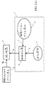
図1(a)は、この発明の一実施例に従った燃焼システムを示すブロック図である。当該燃焼システムは、たとえばタービンエンジンまたは火花点火または圧縮点火エンジンなどの、但しこれらには限定されない燃焼器のための液体燃料または液化ガスとともに用いられる典型的な燃焼器5(この明細書において同義で「燃焼装置」とも称される)を含む。図1(a)に図示のとおり、液体燃料/液化ガス気化ユニット1は燃焼器5に接続される。酸素の少ない気化された燃料の流れ8は気化ユニット1から燃焼器5に供給される。また、燃焼器5には、空気源などの酸素が加えられたガスの流れ9が投入される。一実施例においては、燃焼器5は、気化された燃料の流れ8と酸素が加えられたガスの流れ9の
流れとを適切に混合するという特徴を含む。
FIG. 1A is a block diagram showing a combustion system according to an embodiment of the present invention. The combustion system is typically a combustor 5 (synonymous in this specification) used with liquid fuel or liquefied gas for a combustor such as, but not limited to, a turbine engine or a spark ignition or compression ignition engine. Also referred to as “combustion device”). As shown in FIG. 1A, the liquid fuel / liquefied gas vaporization unit 1 is connected to a
気化ユニット1は、酸素の少ないガスの流れ源2と、液体燃料/液化ガス源3(この明細書中において同義で「液体燃料」および/または「液化燃料」とも称される)と、気化器ユニット4とを含む。当該液体燃料/液化ガス気化ユニット4は、液体燃料/液化ガス源3および酸素の少ないガスの流れ源2からそれぞれ供給される流れ6、7を混合しかつ気化する。他の多くの方法を用いて液体燃料の流れ6と酸素の少ないガスの流れ2とを気化させることができる。混合および気化が行なわれる順序は重要ではない。いくつかの実施例においては、混合および気化は、酸素の少ない流れが液体燃料を気化するのに十分な温度に予め加熱される場合などに同時に行なわれる。他の実施例においては、液体燃料の流れ6は、酸素の少ないガスの流れ7と混合される前に、たとえば液体燃料を加熱することによって部分的または完全に気化される。いくつかの実施例においては、酸素の少ないガスの流れ7は、混合および気化の前に加圧および/または加熱される。気化された燃料の流れ8は、酸素の少ない流れと混合することにより自己発火を避けるよう調整され、燃焼プロセスでの使用のために燃焼器5に供給される。
The vaporization unit 1 comprises a low oxygen gas flow source 2, a liquid fuel / liquefied gas source 3 (also referred to herein as “liquid fuel” and / or “liquefied fuel”), a
いくつかの実施例においては、気化された燃料の流れ8の温度は、燃焼器5への移動中に当該気化された燃料の流れ8の温度を露点よりも高いままにするのに十分なほど高い。他の実施例においては、気化された燃料の流れ8の温度は、当該気化された燃料の流れ8が燃焼器5に到達するのに移動する距離が、多くの凝縮が生じるには時間が不十分である程度に短い場合、露点よりも低くなってもよい。さらに他の実施例においては、気化された燃料の流れ8は気化器4と燃焼器5との間で加熱される。
In some embodiments, the temperature of the vaporized
酸素の少ないガスの流れ源2は、一般に約21%のO2を含有するとされる周囲空気に比べて酸素含有量が少ないガスの流れを生成する。この発明のいくつかの実施例においては、酸素の少ないガスの流れは、限界酸素指数(limiting oxygen index)未満の酸素含有量を有する。限界酸素指数(LOI)は局所的な環境における酸素の濃度であるが、その濃度未満では材料は燃焼を維持し得ず、また、当該限界酸素指数(LOI)は異なる種類の液体燃料に応じて変動する。LOIは典型的には約10%〜約14%であり、多くの高次炭化水素燃料に対しては約13%である。源2からのガスの流れの酸素含有量が少なければ少ないほど、自己発火がより抑制される。しかしながら、酸素含有量がより低いガスの流れを生成するのにより多くの仕事量(すなわちエネルギ)が必要とされる。この仕事量は全体的なシステムの効率を低下させるだろう。こうして、いくつかの実施例においては、流れの源2からの酸素含有量は、必要な量だけ自己発火を抑制するのに十分に低い。この量はLOIよりも高くても低くてもよい。この発明の他の実施例においては、酸素の少ないガスの流れ源2は酸素を含有しない。これらの実施例のいくつかにおいては、酸素の少ないガスの流れ源2によって供給されるガスは不活性である。さらに他の実施例においては、源2からのガスは炭化水素(たとえばメタンおよび/または高次炭化水素)を含む。 The low oxygen gas stream source 2 produces a gas stream that has a lower oxygen content compared to ambient air, which is generally considered to contain about 21% O 2 . In some embodiments of the present invention, the low oxygen gas stream has an oxygen content less than a limiting oxygen index. The limiting oxygen index (LOI) is the concentration of oxygen in the local environment, but below that concentration the material cannot sustain combustion, and the limiting oxygen index (LOI) depends on different types of liquid fuels fluctuate. The LOI is typically about 10% to about 14% and about 13% for many higher hydrocarbon fuels. The lower the oxygen content of the gas stream from the source 2, the more self-ignition is suppressed. However, more work (ie energy) is required to produce a gas stream with a lower oxygen content. This workload will reduce the overall system efficiency. Thus, in some embodiments, the oxygen content from stream source 2 is sufficiently low to suppress autoignition by the required amount. This amount may be higher or lower than the LOI. In another embodiment of the invention, the low oxygen gas stream source 2 does not contain oxygen. In some of these embodiments, the gas supplied by the low oxygen gas stream source 2 is inert. In yet other embodiments, the gas from source 2 includes hydrocarbons (eg, methane and / or higher order hydrocarbons).
源2からのガスの流れにおける、自己発火を十分に抑制するのに必要とされる酸素含有量の削減量は、特定の応用例、特に、燃料の品質、混合/気化方式、気化されたガスの流れが燃焼器に到達するのに移動しなければならない距離、気化されたガスの流れが気化器を離れる際の温度、酸素の少ないガスの流れ/燃料混合物が燃焼前に燃焼器でさらされる温度、燃焼器における予混合ゾーンから燃焼ゾーンまでの距離などの要因に依存するだろう。 The amount of oxygen content reduction required to sufficiently suppress self-ignition in the gas flow from source 2 depends on the particular application, in particular the fuel quality, the mixing / vaporization scheme, the vaporized gas. The distance that the gas stream must travel to reach the combustor, the temperature at which the vaporized gas stream leaves the vaporizer, and the low oxygen gas stream / fuel mixture is exposed to the combustor prior to combustion It will depend on factors such as temperature, the distance from the premix zone to the combustion zone in the combustor.
上述のとおり、図1(a)の燃焼器5は、図1(b)に示される予混合燃焼器であり得る。予混合燃焼器は、典型的には、予混合ゾーン5b−1、最初の燃焼ゾーン5b−2、中間ゾーン5b−3および希釈ゾーン5b−4を含む。予混合燃焼器においては、酸素の
少ない気化された燃料ガスの流れ8が予混合ゾーン5b−1に供給され、ここで、酸素が加えられたガスの流れ9a(たとえば空気)と予混合される。酸素が加えられたガスの流れ9aは典型的には他のゾーン5b−2、5b−3、5b−4のうちのいくつかまたはすべてに供給される。RQL燃焼装置においては、酸素の少ない気化された燃料ガスの流れ8がまた、中間ゾーン5b−3に供給される。代替的には、図1(a)の燃焼器5は、図1(c)に図示のとおり、最初の燃焼ゾーン5c−1、中間ゾーン5c−2および希釈ゾーン5c−3を含む拡散燃焼器であり得る。典型的な拡散燃焼器においては、酸素の少ない気化された燃料ガスの流れ8は最初の燃焼ゾーン5c−1に供給され、ここで、酸素が加えられたガスの流れ9aが存在する状態で燃焼される。
As described above, the
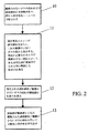
図2は、この発明の好適な一実施例に従った液体燃料/酸素の少ないガス気化システムの動作方法のフローチャートを示す。酸素の少ないガスの流れおよび液体燃料源からの供給物は各々、ステップ10において液体燃料気化ユニットに供給される。液体燃料気化ユニットはステップ11において供給物の流れを混合しかつ気化する。気化エネルギは、酸素の少ないガスの流れによって、または別のエネルギ源から供給され得る。気化された燃料の流れは、酸素の少ない流れと混合することにより自己発火を避けるよう調整されているが、ステップ12において燃焼器に供給される。燃焼器は、ステップ13において、調製された液体燃料/酸素の少ないガスの流れと酸素源とを用いて、可燃性の混合物を作り出す。
FIG. 2 shows a flowchart of a method of operation of a liquid fuel / low oxygen gas vaporization system in accordance with a preferred embodiment of the present invention. The low oxygen gas stream and the feed from the liquid fuel source are each fed to the liquid fuel vaporization unit in
この発明に従った燃焼システムの別の実施例が図3に示される。図3の燃焼システムは、空気圧縮器15(図3には図示されない燃焼空気供給部に接続されている)と、燃焼器5(上述のように予混合燃焼器または拡散燃焼器であり得る)と、タービン16と、排出物を放出するための排気筒17とを有する従来のガスタービンエンジン14を含む。タービンエンジン14はいかなる装置、たとえば発電機18や軍艦のスクリューなどの他の出力装置に結合されてもよい。この実施例においては、排気筒17からの排気流20の一部分を用いて、酸素の少ないガスの流れを液体燃料/液化ガス気化ユニット21に供給する。液体燃料/液化ガス気化ユニット21は従来のガスタービンエンジン14に接続される。気化ユニット21は圧縮器19を含み、当該圧縮器19は、当該ユニット21に接続され得る排気筒排気流20、燃料気化器4および液体燃料/液化ガス源3を加圧する。当該圧縮器19は、ユニット21内に含まれ得るかまたは代替的にはユニット21とは別個であってもよい。
Another embodiment of a combustion system according to the present invention is shown in FIG. The combustion system of FIG. 3 includes an air compressor 15 (connected to a combustion air supply not shown in FIG. 3) and a combustor 5 (which can be a premixed combustor or a diffusion combustor as described above). And a conventional
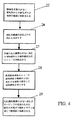
図4は、この発明の実施例に従った、タービンとともに用いられる液体燃料/酸素の少ないガス気化システムの動作の一方法を示すフローチャートである。酸素含有量の少ないタービン排気流がステップ25において圧縮器に供給される。当該圧縮器は、ステップ26においてガスタービン排気流を加圧する。結果として得られる酸素の少ない流れの圧縮器の排出流れと液体燃料の流れとが各々、ステップ27において液体燃料気化器に供給される。圧縮器の排出流れは、ステップ28において液体燃料の流れと混合されて液体燃料を気化する。次いで、酸素の少ない気化された液体燃料の流れが、ステップ29においてガスタービンの燃焼器に供給される。
FIG. 4 is a flowchart illustrating one method of operation of a liquid fuel / low oxygen gas vaporization system for use with a turbine in accordance with an embodiment of the present invention. A turbine exhaust stream having a low oxygen content is fed to the compressor at
いくつかの好ましい実施例においては、タービンエンジン14は、天然ガスで動作するよう構成された既存の希薄予混合装置であり、液体燃料3は高次炭化水素液体燃料である。上述の自己発火の問題に加えて、天然ガスで動作するよう構成された燃焼装置内での高次炭化水素燃料の使用に関連して第2の問題が発生する。つまり、高次炭化水素燃料は天然ガスよりもエネルギ含有量が高いので、天然ガスで動作するよう構成されたエンジンの燃料ガス拡散および計量システムは、通常、高次炭化水素燃料ガスで動作するよう変更を加えることが必要となるだろう。しかしながら、好ましい実施例においては、ガス気化ユニット21は、エンジン14の燃料ガス拡散システムに対する変更が不要となるように酸
素の少ない気化された燃料ガスをタービンエンジン14に供給するよう構成される。これは、気化器4からの酸素の少ない気化された燃料ガスのエネルギ含有量が天然ガスと等しくなるような量の酸素の少ないガスを気化された燃料と混合することによって達成される。これは、エンジン14で用いられる燃料計量方法に依存して、体積または質量ベースでなされてもよい。他の実施例においては、酸素の少ない燃料ガスのエネルギ含有量は天然ガスの含有量よりも高いかまたは低く、燃料拡散システムは、このようなエネルギ含有量がより高いかまたはより低いガスで作動するよう構成される。
In some preferred embodiments, the
一例として、燃料ガスの発熱量はガス分子中の炭素原子の数にほぼ比例している。したがって、ペンタン(C5H12)は、天然ガスの主成分、すなわちメタン(CH4)の発熱量の約5倍である。液化されたペンタンが図3のシステムにおいて液体燃料として用いられる場合、体積ベースでメタンを計量するよう構成された燃料ガス拡散システムを有するエンジン14を用いるために、気化器4は、1つの気化されたペンタンガスの流れと4つの酸素の少ないガスの流れとを含む燃料ガスの流れを出力するよう構成されるだろう。
As an example, the calorific value of the fuel gas is approximately proportional to the number of carbon atoms in the gas molecule. Therefore, pentane (C 5 H 12 ) is about five times the calorific value of the main component of natural gas, that is, methane (CH 4 ). When liquefied pentane is used as liquid fuel in the system of FIG. 3, the
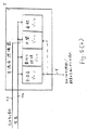
図5は、この発明に従った、ガスタービンエンジン14を含む燃焼システムのさらに別の実施例を示し、当該ガスタービンエンジン14は、圧縮器15と、燃焼器5と、タービン16と、排出物を放出するための排気筒17とを有する。タービン16は、たとえば発電機18や軍艦のスクリューなどの他の装置にも結合され得る。この発明の一実施例の液体燃料/液化ガス気化ユニット31はガスタービンエンジン14に接続可能である。図5aに示される実施例においては、ユニット31は空気分離器32、補助圧縮器33、第2の圧縮器34、燃料気化器4、および液体燃料/液化ガス源3を含み、これらはユニット31内に含まれ得る。または、これらは、代替的にはユニット31とは別個であり当該ユニット31に接続されてもよい。
FIG. 5 illustrates yet another embodiment of a combustion system including a
空気分離器32は、エンジン14の圧縮器15から圧縮空気の流れ(または別の源から圧縮空気の流れ)を取込み、酸素を多く含むガスの流れ41と、典型的には空気に比べて多量の窒素を含む酸素の少ないガスの流れ42とを排出する。多様な空気分離器が当該技術において公知である。いくつかの実施例においては、空気分離ユニットは、吸着と称されるプロセスを用いて酸素を多く含む流れ41と酸素の少ない流れ42とを作り出す。このような実施例においては、空気の流れは、分離を容易にするために3つの大気のうちの或る気圧に圧縮され得る。
The
図5aの実施例においては、酸素を多く含む流れ41が圧縮され、圧縮された酸素を多く含むガスの流れ43が燃焼器5に注入される。酸素の少ない流れ42が補助圧縮器33に供給され、ここで加圧される。結果として得られる圧縮された酸素の少ないガスの流れ45は、次に液体燃料/液化ガス気化ユニット4に供給される。液体燃料/液化ガス気化ユニット4は、液体燃料/液化ガス源3からの液体燃料/液化ガス供給物6を圧縮された酸素の少ない流れ45と高温で混合して、液体燃料/液化ガスを気化する。圧縮された酸素の少ない流れ45とガス供給物6とが混合される比率は、液体燃料3とエンジン14の構成とに依存する。上述のとおり、当該比率は、エンジン14の燃料拡散システムに変更を加えることなく、天然ガスを燃焼させるよう構成されたエンジン14を高次炭化水素液体燃料3で使用することを可能にするよう選択され得る。次いで、気化燃料/酸素の少ない流れ8が燃焼器5に供給される。
In the embodiment of FIG. 5 a, oxygen rich stream 41 is compressed and compressed oxygen
図6は、この発明の実施例に従った、タービンとともに用いるための液体燃料/液化ガス気化システムの動作方法を示すフローチャートである。図6に図示のとおり、圧縮空気は、ステップ51において、空気分離ユニットでの使用のために適切な段階/圧力でガスタービンエンジンの空気圧縮器から取込まれる。空気分離ユニットは、ステップ52において、圧縮空気の流れを取込み、酸素を多く含む流れと酸素の少ない流れとを作り出す。
一実施例においては、酸素を多く含む流れがステップ53において第1の補助圧縮器に供給され、第1の補助圧縮器がステップ54において酸素を多く含む流れを加圧し、加圧された酸素を多く含む流れがステップ55において燃焼器に注入される。いくつかの実施例においては、酸素を多く含む燃料の流れは、燃焼器5の炎の下流側(たとえば、図5(b)および図5(c)にそれぞれ図示される予混合燃焼器などの燃焼器の中間ゾーンもしくは希釈ゾーン、または拡散燃焼器)に注入されて、エンジン14によって放出される汚染物質の量を減ずる。他の実施例においては、酸素を多く含む燃料の流れが圧縮器15からの燃焼用空気と混合されて、これが図5(d)(予混合燃焼器)および図5(e)(拡散燃焼器)に図示される燃焼器5の最初の燃焼ゾーンに供給される。これにより燃焼器の運転範囲が広がり、こうしてより低い等量比で燃焼を行なうこと(すなわちより希薄な燃焼)が可能となり、NOXなどの汚染物質の排出を減らすことができる。さらに他の実施例においては、酸素を多く含む燃料の流れは圧縮器15からの空気と単純に混合され、燃焼器のすべてのゾーンに供給される。
FIG. 6 is a flowchart illustrating a method of operating a liquid fuel / liquefied gas vaporization system for use with a turbine in accordance with an embodiment of the present invention. As shown in FIG. 6, compressed air is taken in
In one embodiment, an oxygen rich stream is fed to the first auxiliary compressor at
空気分離ユニットからの酸素の少ない流れがステップ56において第2の補助圧縮器に供給され、当該第2の補助圧縮器がステップ57において酸素の少ない流れを加圧する。結果として得られる圧縮された酸素の少ない流れは、液体燃料源からの液体燃料/液化ガスの流れとともに、ステップ58において液体燃料気化ユニットに供給される。液体燃料気化ユニットは、ステップ59において、供給された液体燃料/液化ガスの流れを圧縮された酸素の少ない流れと高温で混合して、液体燃料/液化ガスを気化させる。この発明の実施例においては、酸素の少ない流れおよび液体燃料/液化ガスが混合される程度は、さまざまな液体燃料/液化ガスに対し適切な特定の発熱量および/または質量もしくは体積流量の仕様に調節可能である。次に、気化燃料/酸素の少ない流れは、ステップ60において、たとえばタービンでの使用のために既存の天然ガス燃料システムを通じて燃焼器に供給される。
The low oxygen stream from the air separation unit is fed to the second auxiliary compressor at
上述のように、この発明のいくつかの実施例は、既存の燃焼装置に変更を加えることなく天然ガスなどの他の燃料を燃焼させるよう構成されたガスタービンエンジンなどの既存の燃焼装置に供給可能な酸素の少ない燃料ガスの流れを液体燃料から生成するよう構成される。これは、燃料ガスを不活性な酸素の少ない流れと混合することにより、燃焼装置で用いられる計量方法に依存して質量または体積ベースで、天然ガスのエネルギ含有量に等しい燃料ガスのエネルギ含有量を維持することによって達成される。大抵の既存の燃焼装置においては、燃料ガス/燃焼用空気の比率は、混合物がある程度希薄になり得るように制御され得る。この発明の付加的な利点は、酸素の少ない気化された高次炭化水素燃料の多くが同等の条件(すなわち、同じ温度、同じ燃焼用空気(または他の酸素含有ガス)供給など)の下、メタンよりも低い(よりも希薄な)等量比で燃焼可能であることである。たとえば、メタンの最小等量比は典型的には大気中で約0.5であり、多くの高次炭化水素燃料は、大気中でほぼ0.45の等量比で燃焼可能である。より低い等量比を用いることにより、NOXなどの汚染物質の排出が減じられる。上述のとおり、燃焼装置の運転等量比は、空気分離器から燃焼用空気の流れへ酸素を多く含む流れを加えることにより運転範囲が広げられた実施例においてはさらに低い可能性がある。 As mentioned above, some embodiments of the invention provide for existing combustion devices such as gas turbine engines configured to burn other fuels such as natural gas without modification to the existing combustion devices. A possible low oxygen fuel gas stream is configured to generate from liquid fuel. This is by mixing the fuel gas with a stream of inert oxygen and, by mass or volume, depending on the metering method used in the combustion device, the energy content of the fuel gas equal to the energy content of the natural gas Is achieved by maintaining In most existing combustors, the fuel gas / combustion air ratio can be controlled so that the mixture can become somewhat lean. An additional advantage of the present invention is that many of the vaporized higher hydrocarbon fuels with low oxygen have the same conditions (ie, the same temperature, the same combustion air (or other oxygen-containing gas) supply, etc.) It is combustible at an equivalence ratio lower (leaner) than methane. For example, the minimum equivalence ratio of methane is typically about 0.5 in the atmosphere, and many higher hydrocarbon fuels can be combusted in the atmosphere at an equivalence ratio of approximately 0.45. By using a lower equivalence ratio, emissions of pollutants such as NO x are reduced. As mentioned above, the operating equivalence ratio of the combustion device may be even lower in embodiments where the operating range has been expanded by adding a stream rich in oxygen from the air separator to the combustion air stream.
この発明の他の実施例においては、天然ガスよりもエネルギ含有量が高いかまたは低い酸素の少ない燃料ガスが生成される。このような実施例においては、天然ガスで作動するよう構成された燃焼装置が用いられる場合、燃焼装置の燃料拡散/計量システムが適切に変更されることが必要になる可能性がある。 In another embodiment of the present invention, a fuel gas with a lower or higher energy content than natural gas is produced. In such embodiments, if a combustion device configured to operate with natural gas is used, it may be necessary to properly modify the fuel diffusion / metering system of the combustion device.
この発明の実施例が上述の利点に従って説明された。これらの例が単にこの発明の例示に過ぎないことが理解されるだろう。多くの変形例および変更例が当業者には明らかとなるだろう。 Embodiments of the invention have been described in accordance with the above advantages. It will be understood that these examples are merely illustrative of the invention. Many variations and modifications will be apparent to those skilled in the art.
Claims (57)
炭化水素分子を含む液体燃料と、周囲空気よりも酸素含有量の少ない第1のガスの流れとを用いて燃料ガスを生成するステップを含み、前記液体燃料のうちの少なくとも50重量百分率の前記炭化水素分子は少なくとも2つの炭素原子を有し、
前記燃料ガスと第2のガスとを予混合して、燃焼器の燃焼ゾーンの上流における位置でガス混合物を生成するステップとを含み、前記第2のガスは酸素を含み、前記方法はさらに、
前記燃焼器の前記燃焼ゾーンにおいて前記ガス混合物を燃焼させるステップを含み、これにより、前記燃焼ゾーンの上流における前記ガス混合物の自己発火が実質的に抑制される、方法。A method for operating a combustor, comprising:
Generating a fuel gas using a liquid fuel comprising hydrocarbon molecules and a flow of a first gas having a lower oxygen content than ambient air , wherein at least 50 weight percent of the carbonization of the liquid fuel The hydrogen molecule has at least two carbon atoms ,
Premixing the fuel gas with a second gas to produce a gas mixture at a location upstream of the combustion zone of the combustor, wherein the second gas comprises oxygen, and the method further comprises:
Combusting the gas mixture in the combustion zone of the combustor so that self-ignition of the gas mixture upstream of the combustion zone is substantially suppressed.
周囲空気に比べて酸素含有量の少ないガスの流れを用いて高級炭化水素液体燃料を気化して、酸素の少ない燃料ガスを生成するステップと、
前記酸素の少ない燃料ガスと第2のガスとを予混合して、燃焼器の燃焼ゾーンの上流における位置でガス混合物を生成するステップとを含み、前記ガス混合物は前記ガス混合物の燃焼を維持するのに十分な量の酸素を有し、前記ガス混合物は1未満の等量比を有し、前記方法はさらに、
前記燃焼器の前記燃焼ゾーンにおいて前記ガス混合物を燃焼させるステップを含み、これにより、前記燃焼ゾーンの上流における前記ガス混合物の自己発火が実質的に抑制される、方法。A method for operating a combustor configured to be suitable for burning natural gas in a lean premixing system, comprising:
Vaporizing the higher hydrocarbon liquid fuel using a gas stream having a lower oxygen content than ambient air to produce a fuel gas having less oxygen;
Premixing the low oxygen fuel gas and a second gas to produce a gas mixture at a location upstream of the combustion zone of the combustor, the gas mixture maintaining combustion of the gas mixture has a sufficient amount of oxygen to the gas mixture has an equivalence ratio of less than 1, before Symbol method further
Combusting the gas mixture in the combustion zone of the combustor so that self-ignition of the gas mixture upstream of the combustion zone is substantially suppressed.
燃焼器を含み、前記燃焼器は、気化された燃料を受取る入口と、燃焼ゾーンと、前記燃焼ゾーンの上流にある予混合ゾーンとを有し、前記燃焼器は、前記予混合ゾーンにおいて気化された燃料を酸素が加えられたガスの流れと混合してガス混合物を生成し、前記燃焼ゾーンにおいて前記ガス混合物を燃焼させるよう構成されており、前記燃焼システムはさらに、
前記燃焼器の前記入口に接続される燃料気化ユニットを含み、前記燃料気化ユニットは、酸素の少ない気化された燃料ガスの流れを前記入口を介し前記燃焼器に供給するよう構
成され、前記燃料気化ユニットは、液体燃料源に接続可能な第1の入口と酸素の少ないガスの流れに接続可能な第2の入口とを有する燃料気化器を含み、前記液体燃料源からの前記液体燃料のうちの少なくとも50重量百分率の炭化水素分子は少なくとも2つの炭素原子を有する、燃焼システム。A combustion system,
A combustor, the combustor having an inlet for receiving vaporized fuel, a combustion zone, and a premixing zone upstream of the combustion zone, the combustor being vaporized in the premixing zone. The fuel system is configured to mix a fuel with an oxygenated gas stream to form a gas mixture and combust the gas mixture in the combustion zone, the combustion system further comprising:
A fuel vaporization unit connected to the inlet of the combustor, wherein the fuel vaporization unit is configured to supply a flow of vaporized fuel gas with less oxygen to the combustor via the inlet; unit, a fuel vaporizer with a second inlet connectable to a flow of the first inlet and the oxygen-poor gas which can be connected to the liquid fuel source seen including, among the liquid fuel from the liquid fuel source The combustion system wherein at least 50 weight percent of the hydrocarbon molecules have at least two carbon atoms .
燃料気化器と、
液体燃料の流れを供給するよう前記燃料気化器に接続される液体燃料の源と、
酸素の少ないガスの流れの排出物を有する空気分離器とを含み、前記酸素の少ないガスの流れの排出物は前記燃料気化器に接続され、
前記燃料気化器は、前記液体燃料および前記酸素の少ないガスの流れから気化された燃料混合物を生成する、燃料気化ユニット。A fuel vaporization unit,
A fuel vaporizer,
A source of liquid fuel connected to the fuel vaporizer to provide a flow of liquid fuel;
An air separator having a low oxygen gas stream exhaust, wherein the low oxygen gas stream exhaust is connected to the fuel vaporizer;
The fuel vaporizer generates a vaporized fuel mixture from the liquid fuel and the oxygen-poor gas stream.
空気分離器からの酸素の少ないガスと前記気化された液体燃料とを混合するステップと、
前記気化された液体燃料と前記酸素の少ないガスとの混合物を燃焼させるステップとを含む、方法。Vaporizing liquid fuel; and
Mixing the low-oxygen gas from the air separator with the vaporized liquid fuel;
Combusting a mixture of the vaporized liquid fuel and the low oxygen gas.
前記加熱された酸素の少ないガスを用いて液体燃料を気化して、気化された燃料混合物を生成するステップと、
前記気化された燃料混合物を燃焼させるステップとを含む、方法。Heating the low oxygen gas from the air separator;
Vaporizing liquid fuel using the heated low oxygen gas to produce a vaporized fuel mixture;
Combusting the vaporized fuel mixture.
Applications Claiming Priority (3)
| Application Number | Priority Date | Filing Date | Title |
|---|---|---|---|
| US41718402P | 2002-10-10 | 2002-10-10 | |
| US43065302P | 2002-12-04 | 2002-12-04 | |
| PCT/US2003/032423 WO2004033886A2 (en) | 2002-10-10 | 2003-10-10 | System for vaporization of liquid fuels for combustion and method of use |
Publications (3)
| Publication Number | Publication Date |
|---|---|
| JP2006503259A JP2006503259A (en) | 2006-01-26 |
| JP2006503259A5 JP2006503259A5 (en) | 2006-11-24 |
| JP4490912B2 true JP4490912B2 (en) | 2010-06-30 |
Family
ID=32096183
Family Applications (1)
| Application Number | Title | Priority Date | Filing Date |
|---|---|---|---|
| JP2005501180A Expired - Lifetime JP4490912B2 (en) | 2002-10-10 | 2003-10-10 | System and method of use for vaporizing liquid fuel for combustion |
Country Status (16)
| Country | Link |
|---|---|
| US (4) | US7089745B2 (en) |
| EP (2) | EP1549881B1 (en) |
| JP (1) | JP4490912B2 (en) |
| KR (1) | KR100785955B1 (en) |
| AU (1) | AU2003284124C1 (en) |
| CA (1) | CA2501862C (en) |
| DK (2) | DK3078909T3 (en) |
| ES (2) | ES2925692T3 (en) |
| HK (2) | HK1085262A1 (en) |
| HU (2) | HUE028936T2 (en) |
| MX (2) | MXPA05003786A (en) |
| NO (1) | NO339278B1 (en) |
| NZ (1) | NZ539362A (en) |
| PT (1) | PT3078909T (en) |
| SI (2) | SI3078909T1 (en) |
| WO (1) | WO2004033886A2 (en) |
Families Citing this family (99)
| Publication number | Priority date | Publication date | Assignee | Title |
|---|---|---|---|---|
| DK3078909T3 (en) * | 2002-10-10 | 2022-08-15 | Lpp Comb Llc | Method for vaporizing liquid fuels for combustion |
| US6935117B2 (en) | 2003-10-23 | 2005-08-30 | United Technologies Corporation | Turbine engine fuel injector |
| US7011048B2 (en) * | 2004-07-22 | 2006-03-14 | Ener1, Inc. | Method and apparatus for liquid fuel preparation to improve combustion |
| ZA200704800B (en) * | 2004-12-08 | 2008-10-29 | Lpp Comb Llc | Method and apparatus for conditioning liquid hydrocarbon fuels |
| US7765810B2 (en) * | 2005-11-15 | 2010-08-03 | Precision Combustion, Inc. | Method for obtaining ultra-low NOx emissions from gas turbines operating at high turbine inlet temperatures |
| US8529646B2 (en) | 2006-05-01 | 2013-09-10 | Lpp Combustion Llc | Integrated system and method for production and vaporization of liquid hydrocarbon fuels for combustion |
| US8460409B2 (en) * | 2006-05-08 | 2013-06-11 | Ceramatec, Inc. | Plasma-catalyzed fuel reformer |
| WO2007133511A2 (en) * | 2006-05-08 | 2007-11-22 | Ceramatec, Inc. | Plasma-catalyzed, thermally-integrated, reformer for fuel cell systems |
| US10422534B2 (en) * | 2006-06-26 | 2019-09-24 | Joseph Michael Teets | Fuel air premix chamber for a gas turbine engine |
| US8618436B2 (en) | 2006-07-14 | 2013-12-31 | Ceramatec, Inc. | Apparatus and method of oxidation utilizing a gliding electric arc |
| US7827797B2 (en) * | 2006-09-05 | 2010-11-09 | General Electric Company | Injection assembly for a combustor |
| US7950238B2 (en) * | 2006-10-26 | 2011-05-31 | General Electric Company | Method for detecting onset of uncontrolled fuel in a gas turbine combustor |
| JP4963406B2 (en) * | 2006-11-16 | 2012-06-27 | 一般財団法人電力中央研究所 | Gas turbine combustor and operation method thereof |
| US7882704B2 (en) * | 2007-01-18 | 2011-02-08 | United Technologies Corporation | Flame stability enhancement |
| NO20070649L (en) * | 2007-02-05 | 2008-08-06 | Ntnu Technology Transfer As | Gas turbine |
| JP5180236B2 (en) | 2007-02-23 | 2013-04-10 | セラマテック・インク | Ceramic electrode for sliding electric arc |
| JP5013414B2 (en) * | 2007-04-27 | 2012-08-29 | 一般財団法人電力中央研究所 | Gas turbine system and power generation system |
| EP2017535A1 (en) * | 2007-07-19 | 2009-01-21 | Siemens Aktiengesellschaft | Liquid fuelled gas turbine |
| US8171716B2 (en) * | 2007-08-28 | 2012-05-08 | General Electric Company | System and method for fuel and air mixing in a gas turbine |
| CN101802366A (en) * | 2007-09-28 | 2010-08-11 | 财团法人电力中央研究所 | Turbine facility and power generating apparatus |
| US8671658B2 (en) | 2007-10-23 | 2014-03-18 | Ener-Core Power, Inc. | Oxidizing fuel |
| JP5187730B2 (en) * | 2007-11-15 | 2013-04-24 | 一般財団法人電力中央研究所 | Boiler and power generation system |
| US20090193809A1 (en) * | 2008-02-04 | 2009-08-06 | Mark Stewart Schroder | Method and system to facilitate combined cycle working fluid modification and combustion thereof |
| EP2107313A1 (en) * | 2008-04-01 | 2009-10-07 | Siemens Aktiengesellschaft | Fuel staging in a burner |
| CN102076941B (en) * | 2008-10-01 | 2013-11-06 | 三菱重工业株式会社 | Gas turbine device |
| US8701413B2 (en) * | 2008-12-08 | 2014-04-22 | Ener-Core Power, Inc. | Oxidizing fuel in multiple operating modes |
| US8490406B2 (en) * | 2009-01-07 | 2013-07-23 | General Electric Company | Method and apparatus for controlling a heating value of a low energy fuel |
| US20100180565A1 (en) * | 2009-01-16 | 2010-07-22 | General Electric Company | Methods for increasing carbon dioxide content in gas turbine exhaust and systems for achieving the same |
| US8986002B2 (en) | 2009-02-26 | 2015-03-24 | 8 Rivers Capital, Llc | Apparatus for combusting a fuel at high pressure and high temperature, and associated system |
| MX345743B (en) * | 2009-02-26 | 2017-02-14 | 8 Rivers Capital Llc | Apparatus and method for combusting a fuel at high pressure and high temperature, and associated system and device. |
| US9068743B2 (en) * | 2009-02-26 | 2015-06-30 | 8 Rivers Capital, LLC & Palmer Labs, LLC | Apparatus for combusting a fuel at high pressure and high temperature, and associated system |
| US20110067405A1 (en) * | 2009-09-18 | 2011-03-24 | Concepts Eti, Inc. | Integrated Ion Transport Membrane and Combustion Turbine System |
| US8858223B1 (en) * | 2009-09-22 | 2014-10-14 | Proe Power Systems, Llc | Glycerin fueled afterburning engine |
| US8381525B2 (en) * | 2009-09-30 | 2013-02-26 | General Electric Company | System and method using low emissions gas turbine cycle with partial air separation |
| US20110083444A1 (en) * | 2009-10-09 | 2011-04-14 | General Electric Company | Low btu fuel injection system |
| US8613187B2 (en) * | 2009-10-23 | 2013-12-24 | General Electric Company | Fuel flexible combustor systems and methods |
| US20110138766A1 (en) * | 2009-12-15 | 2011-06-16 | General Electric Company | System and method of improving emission performance of a gas turbine |
| US20110265445A1 (en) * | 2010-04-30 | 2011-11-03 | General Electric Company | Method for Reducing CO2 Emissions in a Combustion Stream and Industrial Plants Utilizing the Same |
| MY156099A (en) * | 2010-07-02 | 2016-01-15 | Exxonmobil Upstream Res Co | Systems and methods for controlling combustion of a fuel |
| US8813472B2 (en) * | 2010-10-21 | 2014-08-26 | General Electric Company | System and method for controlling a semi-closed power cycle system |
| WO2012058277A1 (en) * | 2010-10-26 | 2012-05-03 | Icr Tubine Engine Corporation | Utilizing heat discarded from a gas turbine engine |
| US8863525B2 (en) | 2011-01-03 | 2014-10-21 | General Electric Company | Combustor with fuel staggering for flame holding mitigation |
| US9074530B2 (en) * | 2011-01-13 | 2015-07-07 | General Electric Company | Stoichiometric exhaust gas recirculation and related combustion control |
| US8931283B2 (en) | 2011-01-21 | 2015-01-13 | General Electric Company | Reformed multi-fuel premixed low emission combustor and related method |
| US8794212B2 (en) | 2011-07-29 | 2014-08-05 | General Electric Company | Engine and method of operating engine |
| US8453462B2 (en) | 2011-08-25 | 2013-06-04 | General Electric Company | Method of operating a stoichiometric exhaust gas recirculation power plant |
| US8245493B2 (en) | 2011-08-25 | 2012-08-21 | General Electric Company | Power plant and control method |
| US8266913B2 (en) | 2011-08-25 | 2012-09-18 | General Electric Company | Power plant and method of use |
| US8453461B2 (en) | 2011-08-25 | 2013-06-04 | General Electric Company | Power plant and method of operation |
| US9127598B2 (en) | 2011-08-25 | 2015-09-08 | General Electric Company | Control method for stoichiometric exhaust gas recirculation power plant |
| US8713947B2 (en) * | 2011-08-25 | 2014-05-06 | General Electric Company | Power plant with gas separation system |
| US8205455B2 (en) | 2011-08-25 | 2012-06-26 | General Electric Company | Power plant and method of operation |
| US8266883B2 (en) | 2011-08-25 | 2012-09-18 | General Electric Company | Power plant start-up method and method of venting the power plant |
| US8347600B2 (en) | 2011-08-25 | 2013-01-08 | General Electric Company | Power plant and method of operation |
| US8245492B2 (en) | 2011-08-25 | 2012-08-21 | General Electric Company | Power plant and method of operation |
| US9222415B2 (en) * | 2012-03-06 | 2015-12-29 | Hamilton Sundstrand Corporation | Gas turbine engine fuel heating system |
| US9726374B2 (en) | 2012-03-09 | 2017-08-08 | Ener-Core Power, Inc. | Gradual oxidation with flue gas |
| US9567903B2 (en) | 2012-03-09 | 2017-02-14 | Ener-Core Power, Inc. | Gradual oxidation with heat transfer |
| US9534780B2 (en) | 2012-03-09 | 2017-01-03 | Ener-Core Power, Inc. | Hybrid gradual oxidation |
| US10094288B2 (en) | 2012-07-24 | 2018-10-09 | Icr Turbine Engine Corporation | Ceramic-to-metal turbine volute attachment for a gas turbine engine |
| CN102921268B (en) * | 2012-10-26 | 2015-03-18 | 广州市华南橡胶轮胎有限公司 | System for reducing nitrogen content of flue gas |
| US10100741B2 (en) | 2012-11-02 | 2018-10-16 | General Electric Company | System and method for diffusion combustion with oxidant-diluent mixing in a stoichiometric exhaust gas recirculation gas turbine system |
| US10407990B2 (en) | 2012-11-16 | 2019-09-10 | U.S. Well Services, LLC | Slide out pump stand for hydraulic fracturing equipment |
| US9745840B2 (en) | 2012-11-16 | 2017-08-29 | Us Well Services Llc | Electric powered pump down |
| US10232332B2 (en) | 2012-11-16 | 2019-03-19 | U.S. Well Services, Inc. | Independent control of auger and hopper assembly in electric blender system |
| US9995218B2 (en) | 2012-11-16 | 2018-06-12 | U.S. Well Services, LLC | Turbine chilling for oil field power generation |
| US11476781B2 (en) | 2012-11-16 | 2022-10-18 | U.S. Well Services, LLC | Wireline power supply during electric powered fracturing operations |
| US11449018B2 (en) | 2012-11-16 | 2022-09-20 | U.S. Well Services, LLC | System and method for parallel power and blackout protection for electric powered hydraulic fracturing |
| US9893500B2 (en) | 2012-11-16 | 2018-02-13 | U.S. Well Services, LLC | Switchgear load sharing for oil field equipment |
| US9017437B2 (en) | 2012-12-11 | 2015-04-28 | Ceramatec, Inc. | Method for forming synthesis gas using a plasma-catalyzed fuel reformer |
| US10386019B2 (en) * | 2013-03-15 | 2019-08-20 | Southwire Company, Llc | Flow control and gas metering process |
| US9422868B2 (en) * | 2013-04-09 | 2016-08-23 | General Electric Company | Simple cycle gas turbomachine system having a fuel conditioning system |
| US9347376B2 (en) | 2013-04-24 | 2016-05-24 | General Electric Company | Liquified fuel backup fuel supply for a gas turbine |
| KR101945407B1 (en) * | 2013-07-02 | 2019-02-07 | 한화에어로스페이스 주식회사 | Liquid fuel evaporating system |
| US9371776B2 (en) | 2013-08-20 | 2016-06-21 | Darren Levine | Dual flow air injection intraturbine engine and method of operating same |
| US20150082800A1 (en) * | 2013-09-25 | 2015-03-26 | Korea Electric Power Corporation | Method for suppressing generation of yellow plum of complex thermal power plant using high thermal capacity gas |
| US20150260131A1 (en) * | 2014-03-17 | 2015-09-17 | Woodward, Inc. | Supplying Oxygen to an Engine |
| US8925518B1 (en) | 2014-03-17 | 2015-01-06 | Woodward, Inc. | Use of prechambers with dual fuel source engines |
| EP3161384A1 (en) * | 2014-06-26 | 2017-05-03 | Siemens Energy, Inc. | Axial stage combustion system with exhaust gas recirculation |
| US20160311551A1 (en) * | 2015-03-19 | 2016-10-27 | Hamilton Sundstrand Corporation | Engine proximate nitrogen generation system for an aircraft |
| US10265068B2 (en) | 2015-12-30 | 2019-04-23 | Ethicon Llc | Surgical instruments with separable motors and motor control circuits |
| US11208959B2 (en) * | 2016-11-09 | 2021-12-28 | General Electric Company | System and method for flexible fuel usage for gas turbines |
| US11248529B2 (en) * | 2016-12-13 | 2022-02-15 | General Electric Company | Methods for startup and operation of gas turbine combined cycle power plants using NMHC fuels |
| US10718266B2 (en) * | 2017-01-31 | 2020-07-21 | General Electric Company | Vaporization system for combustion system |
| BR112019018476A2 (en) | 2017-03-07 | 2020-04-14 | 8 Rivers Capital Llc | system and method for the combustion of solid fuels and derivatives thereof |
| WO2018162994A1 (en) | 2017-03-07 | 2018-09-13 | 8 Rivers Capital, Llc | System and method for operation of a flexible fuel combustor for a gas turbine |
| CN109812832A (en) * | 2017-11-21 | 2019-05-28 | 吴鲜家 | High-effect combustion control system and its method |
| US10648311B2 (en) | 2017-12-05 | 2020-05-12 | U.S. Well Services, LLC | High horsepower pumping configuration for an electric hydraulic fracturing system |
| US10598258B2 (en) | 2017-12-05 | 2020-03-24 | U.S. Well Services, LLC | Multi-plunger pumps and associated drive systems |
| PL3728959T3 (en) * | 2017-12-22 | 2022-06-13 | Giovanni D'ARIENZO | Cogeneration system for a boiler |
| WO2020021456A1 (en) | 2018-07-23 | 2020-01-30 | 8 Rivers Capital, Llc | System and method for power generation with flameless combustion |
| US10648270B2 (en) | 2018-09-14 | 2020-05-12 | U.S. Well Services, LLC | Riser assist for wellsites |
| US11578577B2 (en) | 2019-03-20 | 2023-02-14 | U.S. Well Services, LLC | Oversized switchgear trailer for electric hydraulic fracturing |
| WO2020231483A1 (en) | 2019-05-13 | 2020-11-19 | U.S. Well Services, LLC | Encoderless vector control for vfd in hydraulic fracturing applications |
| WO2020251978A1 (en) | 2019-06-10 | 2020-12-17 | U.S. Well Services, LLC | Integrated fuel gas heater for mobile fuel conditioning equipment |
| US11459863B2 (en) | 2019-10-03 | 2022-10-04 | U.S. Well Services, LLC | Electric powered hydraulic fracturing pump system with single electric powered multi-plunger fracturing pump |
| CN111018340B (en) * | 2020-01-03 | 2022-03-15 | 南京玻璃纤维研究设计院有限公司 | Flame injection method and system |
| JP7337005B2 (en) * | 2020-02-26 | 2023-09-01 | 三菱重工業株式会社 | gas turbine plant |
| US11866182B2 (en) * | 2020-05-01 | 2024-01-09 | General Electric Company | Fuel delivery system having a fuel oxygen reduction unit |
Family Cites Families (162)
| Publication number | Priority date | Publication date | Assignee | Title |
|---|---|---|---|---|
| US163323A (en) * | 1875-05-18 | Improvement in the manufacture of gas | ||
| USRE24682E (en) * | 1959-08-18 | johnson | ||
| US696909A (en) * | 1901-01-24 | 1902-04-01 | Samuel J Miller | Carbureting device for explosive-engines. |
| US964031A (en) * | 1904-05-31 | 1910-07-12 | Louis K Leahy | Liquid-hydrocarbon-burning apparatus. |
| US1544607A (en) * | 1923-10-29 | 1925-07-07 | Simmons Henry Emette | Oil burner and vaporizer construction |
| US1755846A (en) * | 1926-07-19 | 1930-04-22 | Noel A Steed | Gas feeder |
| US2256785A (en) | 1932-02-13 | 1941-09-23 | Gasaccumulator Svenska Ab | Fuel combustion |
| US2216178A (en) | 1936-11-10 | 1940-10-01 | Gasaccumulator Svenska Ab | Fuel combustion |
| US2268603A (en) * | 1939-04-14 | 1942-01-06 | Koppers Co Inc | Regenerative gas heater |
| CH221394A (en) * | 1941-03-24 | 1942-05-31 | W Blanc | Process for supplying an internal combustion engine and installation for implementing this process. |
| US2377342A (en) * | 1943-09-02 | 1945-06-05 | John R Holicer | Method and apparatus for treating and generating liquefied petroleum gas |
| US2701608A (en) * | 1951-02-03 | 1955-02-08 | Thermal Res And Engineering Co | Burner |
| DE1196603B (en) * | 1960-11-29 | 1965-07-15 | Willi Broedlin | Infrared burner for liquid fuels |
| US3229464A (en) * | 1962-01-15 | 1966-01-18 | Bendix Corp | Combustor comprising a flame tube and insulating means |
| US3545902A (en) | 1968-09-23 | 1970-12-08 | Frank W Bailey | Blue-flame gun burner process and apparatus for liquid hydrocarbon fuel |
| US3564847A (en) * | 1968-10-11 | 1971-02-23 | Curtiss Wright Corp | Combustion device for gas turbine engines |
| JPS4928282B1 (en) * | 1968-11-30 | 1974-07-25 | ||
| US3597134A (en) * | 1969-01-23 | 1971-08-03 | Frank W Bailey | Liquid fuel burning apparatus |
| US3568934A (en) * | 1969-02-10 | 1971-03-09 | Peabody Engineering Corp | Gas ring for fuel burner |
| US3576382A (en) * | 1969-02-25 | 1971-04-27 | Harald Finnstrand | Fuel burner |
| US3603711A (en) | 1969-09-17 | 1971-09-07 | Edgar S Downs | Combination pressure atomizer and surface-type burner for liquid fuel |
| US3866585A (en) | 1970-10-19 | 1975-02-18 | Richard D Kopa | High energy fuel atomization and a dual carburetion embodying same |
| US3788065A (en) * | 1970-10-26 | 1974-01-29 | United Aircraft Corp | Annular combustion chamber for dissimilar fluids in swirling flow relationship |
| US3973008A (en) * | 1970-12-30 | 1976-08-03 | Kabushiki Kaisha Shimizu Manzo Shoten | Konjac mannan |
| US3832985A (en) | 1971-06-11 | 1974-09-03 | R Edde | Non-pollution carburetion system for engines |
| FR2157328A5 (en) * | 1971-10-18 | 1973-06-01 | Mitsubishi Electric Corp | |
| US4033725A (en) * | 1972-02-24 | 1977-07-05 | John Zink Company | Apparatus for NOx control using steam-hydrocarbon injection |
| US3800533A (en) * | 1972-06-13 | 1974-04-02 | Azapco Inc | Apparatus and method for reducing harmful products of combustion |
| US3840321A (en) * | 1972-09-29 | 1974-10-08 | F Moench | Fuel vaporizer burner assembly and method |
| US4040403A (en) * | 1974-02-21 | 1977-08-09 | William Lester Rose | Air-fuel mixture control system |
| US3986815A (en) | 1974-04-24 | 1976-10-19 | Dowa Co., Ltd. | Burner for burning liquid fuel in gasified form |
| US4047880A (en) | 1974-05-15 | 1977-09-13 | Antonio Caldarelli | Fluids distributor for energized-fluid systems |
| GB1481617A (en) * | 1974-10-07 | 1977-08-03 | Rolls Royce | Gas turbine fuel burners |
| US3973395A (en) | 1974-12-18 | 1976-08-10 | United Technologies Corporation | Low emission combustion chamber |
| US3937008A (en) | 1974-12-18 | 1976-02-10 | United Technologies Corporation | Low emission combustion chamber |
| US4045956A (en) | 1974-12-18 | 1977-09-06 | United Technologies Corporation | Low emission combustion chamber |
| US4058977A (en) | 1974-12-18 | 1977-11-22 | United Technologies Corporation | Low emission combustion chamber |
| US4004875A (en) | 1975-01-23 | 1977-01-25 | John Zink Company | Low nox burner |
| DE2503193A1 (en) | 1975-01-27 | 1976-07-29 | Linde Ag | PROCESS FOR PRODUCING A HEATING GAS BY PRESSURE GASIFICATION OF CARBON FUELS |
| US4025282A (en) | 1975-05-21 | 1977-05-24 | John Zink Company | Apparatus to burn liquid fuels in a gaseous fuel burner |
| US4013396A (en) * | 1975-08-25 | 1977-03-22 | Tenney William L | Fuel aerosolization apparatus and method |
| US3990831A (en) | 1975-09-04 | 1976-11-09 | Consolidated Natural Gas Service Co., Inc. | Recirculating burner |
| DE2542719A1 (en) * | 1975-09-25 | 1977-04-07 | Daimler Benz Ag | COMBUSTION CHAMBER |
| US4008041A (en) * | 1975-10-02 | 1977-02-15 | Gerald Alton Roffe | Apparatus for the gas phase combustion of liquid fuels |
| US4023538A (en) * | 1975-10-24 | 1977-05-17 | Econo Fuel Systems, Inc. | Hot fuel gas generator |
| US4094291A (en) * | 1976-02-23 | 1978-06-13 | Ford Motor Company | Apparatus for mixing a vaporized liquid fuel with air |
| US4044875A (en) * | 1976-06-14 | 1977-08-30 | Walter Kidde & Company, Inc. | Removable funnel for a coin operated apparatus |
| US4173254A (en) * | 1976-06-21 | 1979-11-06 | Texaco Inc. | Partial oxidation process |
| US4099382A (en) * | 1976-06-21 | 1978-07-11 | Texaco Inc. | By-product superheated steam from the partial oxidation process |
| US4145998A (en) | 1976-07-30 | 1979-03-27 | Econo Fuel Systems, Inc. | Hot fuel gas generator |
| US4289475A (en) * | 1977-01-05 | 1981-09-15 | Selas Corporation Of America | Steam vaporization of oil |
| US4140473A (en) * | 1977-01-13 | 1979-02-20 | Allied Chemical Corporation | Apparatus and method to control process to replace natural gas with fuel oil in a natural gas burner |
| US4212163A (en) * | 1978-06-16 | 1980-07-15 | Mikina Stanley J | Heat engine |
| FR2429967A1 (en) | 1978-06-26 | 1980-01-25 | Le Mer Joseph | PROCESS FOR COMBUSTING A LIQUID FUEL AND BURNER FOR ITS IMPLEMENTATION |
| DE2835852C2 (en) | 1978-08-16 | 1982-11-25 | Kraftwerk Union AG, 4330 Mülheim | Combined gas-steam power plant with a gasification device for the fuel |
| DE2836534C2 (en) * | 1978-08-21 | 1982-09-02 | Oertli AG Dübendorf, Dübendorf | Process for burning liquid fuel and burners for carrying out the process |
| DE2912519C2 (en) * | 1979-03-29 | 1984-03-15 | Kernforschungsanlage Jülich GmbH, 5170 Jülich | Burners for liquid fuel and combustion air |
| US4399079A (en) * | 1979-04-04 | 1983-08-16 | Jacob H. Grayson | Method and apparatus for generating vapor of a volatile liquid fuel and operating an internal combustion engine therewith |
| US4270506A (en) * | 1979-05-01 | 1981-06-02 | Jacob H. Grayson | Generating vapor of a volatile normally liquid fuel and operating an internal combustion engine therewith |
| US4375799A (en) * | 1980-04-16 | 1983-03-08 | Swanson Clifford S | Fuel vaporization system |
| JPS56160515A (en) * | 1980-05-13 | 1981-12-10 | Showa Tansan Kk | Burning method for liquefied petroleum gas |
| US4416613A (en) | 1980-08-05 | 1983-11-22 | Barisoff Leonard M | Blowpipe type of burner |
| US4333735A (en) * | 1981-03-16 | 1982-06-08 | Exxon Research & Engineering Co. | Process and apparatus for measuring gaseous fixed nitrogen species |
| US4443180A (en) * | 1981-05-11 | 1984-04-17 | Honeywell Inc. | Variable firing rate oil burner using aeration throttling |
| US4659743A (en) * | 1981-10-09 | 1987-04-21 | The United States Of America As Represented By The United States Department Of Energy | Process and catalyst for converting synthesis gas to liquid hydrocarbon mixture |
| US4483832A (en) | 1982-03-30 | 1984-11-20 | Phillips Petroleum Company | Recovery of heat values from vitiated gaseous mixtures |
| US4784599A (en) * | 1982-05-14 | 1988-11-15 | Garbo Paul W | Liquid fuel combustion with porous fiber burner |
| SE8204941L (en) * | 1982-08-30 | 1984-03-01 | Sandstroem Christer | OLJEBRENNARE |
| US4480986A (en) | 1983-09-14 | 1984-11-06 | Sea-Labs, Inc. | Liquid fuel vaporizing burner |
| DE3408937A1 (en) | 1984-01-31 | 1985-08-08 | BBC Aktiengesellschaft Brown, Boveri & Cie., Baden, Aargau | COMBINED GAS / VAPOR POWER PLANT |
| KR890000327B1 (en) | 1984-04-19 | 1989-03-14 | 도오도오 기기 가부시기가이샤 | Method and apparatus for gasifying and combusting liquid fuel |
| US4606720A (en) * | 1984-09-17 | 1986-08-19 | Foster-Miller, Inc. | Pre-vaporizing liquid fuel burner |
| ATE34201T1 (en) | 1985-08-05 | 1988-05-15 | Siemens Ag | COMBINED GAS AND STEAM TURBINE POWER PLANT. |
| DE3609611C2 (en) * | 1985-08-29 | 1994-01-27 | Bosch Gmbh Robert | Exhaust gas recirculation control device for an internal combustion engine |
| US4838029A (en) * | 1986-09-10 | 1989-06-13 | The United States Of America As Represented By The Secretary Of The Air Force | Externally vaporizing system for turbine combustor |
| US4909728A (en) * | 1986-09-26 | 1990-03-20 | Matsushita Electric Industrial Co., Ltd. | Combustion apparatus |
| US4928015A (en) * | 1987-08-19 | 1990-05-22 | Ford Motor Company | Measuring multicomponent constituency of gas emission flow |
| US5146592A (en) * | 1987-09-14 | 1992-09-08 | Visual Information Technologies, Inc. | High speed image processing computer with overlapping windows-div |
| DE3734346A1 (en) * | 1987-10-10 | 1989-04-27 | Kernforschungsanlage Juelich | METHOD AND CYLINDER HEAD FOR SUPPLYING FUEL IN A PISTON ENGINE |
| US5015173A (en) * | 1988-06-09 | 1991-05-14 | Vth Ag Verfahrenstechnik Fur Heizung | Burner for the combustion of liquids in the gaseous state |
| GB8902034D0 (en) | 1989-01-31 | 1989-03-22 | Kent Scient Ind Projects | Optical displacement sensor |
| US4907565A (en) | 1989-02-22 | 1990-03-13 | Caterpillar Inc. | High pressure gasifier and diesel cycle internal combustion engine system |
| US5035227A (en) * | 1990-02-02 | 1991-07-30 | Hansen Herbert N W | Vaporizer for internal combustion steam engine |
| US5156002A (en) * | 1990-03-05 | 1992-10-20 | Rolf J. Mowill | Low emissions gas turbine combustor |
| FR2667134B1 (en) * | 1990-09-24 | 1995-07-21 | Pavese Guy | METHOD FOR IMPROVING COMBUSTION FOR A BLOW AIR BURNER AND MEANS FOR CARRYING OUT IT. |
| US5207053A (en) | 1991-05-15 | 1993-05-04 | United Technologies Corporation | Method and system for staged rich/lean combustion |
| US5165224A (en) | 1991-05-15 | 1992-11-24 | United Technologies Corporation | Method and system for lean premixed/prevaporized combustion |
| US5138163A (en) * | 1991-09-09 | 1992-08-11 | Ford Motor Company | Direct sampling of engine emissions for instantaneous analysis |
| ATE142324T1 (en) * | 1992-02-28 | 1996-09-15 | Fuellemann Patent Ag | BURNER, ESPECIALLY OIL BURNER OR COMBINED OIL/GAS BURNER |
| US5238396A (en) | 1992-06-18 | 1993-08-24 | The Boc Group, Inc. | Fuel-burner method and apparatus |
| US5295350A (en) * | 1992-06-26 | 1994-03-22 | Texaco Inc. | Combined power cycle with liquefied natural gas (LNG) and synthesis or fuel gas |
| DE4301100C2 (en) | 1993-01-18 | 2002-06-20 | Alstom Schweiz Ag Baden | Process for operating a combined cycle power plant with coal or oil gasification |
| JPH0826780B2 (en) * | 1993-02-26 | 1996-03-21 | 石川島播磨重工業株式会社 | Partially regenerative two-fluid gas turbine |
| US5388395A (en) * | 1993-04-27 | 1995-02-14 | Air Products And Chemicals, Inc. | Use of nitrogen from an air separation unit as gas turbine air compressor feed refrigerant to improve power output |
| US5459994A (en) * | 1993-05-28 | 1995-10-24 | Praxair Technology, Inc. | Gas turbine-air separation plant combination |
| US5359847B1 (en) | 1993-06-01 | 1996-04-09 | Westinghouse Electric Corp | Dual fuel ultra-flow nox combustor |
| DE4318405C2 (en) * | 1993-06-03 | 1995-11-02 | Mtu Muenchen Gmbh | Combustion chamber arrangement for a gas turbine |
| US5377483A (en) | 1993-07-07 | 1995-01-03 | Mowill; R. Jan | Process for single stage premixed constant fuel/air ratio combustion |
| US6220034B1 (en) | 1993-07-07 | 2001-04-24 | R. Jan Mowill | Convectively cooled, single stage, fully premixed controllable fuel/air combustor |
| GB9314112D0 (en) * | 1993-07-08 | 1993-08-18 | Northern Eng Ind | Low nox air and fuel/air nozzle assembly |
| US5794431A (en) * | 1993-07-14 | 1998-08-18 | Hitachi, Ltd. | Exhaust recirculation type combined plant |
| DE4325802B4 (en) * | 1993-07-31 | 2005-07-07 | Alstom | Method for operating a gas turbine plant with liquid or gaseous fuel |
| DE4326802A1 (en) | 1993-08-10 | 1995-02-16 | Abb Management Ag | Fuel lance for liquid and / or gaseous fuels and process for their operation |
| US5345756A (en) * | 1993-10-20 | 1994-09-13 | Texaco Inc. | Partial oxidation process with production of power |
| US5848885A (en) * | 1993-12-03 | 1998-12-15 | Nippon Furnace Kogyo Kabushiki Kaisha | Regenerative burner and regenerative heat exchange system applicable thereto |
| US5713195A (en) * | 1994-09-19 | 1998-02-03 | Ormat Industries Ltd. | Multi-fuel, combined cycle power plant method and apparatus |
| US5572861A (en) | 1995-04-12 | 1996-11-12 | Shao; Yulin | S cycle electric power system |
| US6170264B1 (en) * | 1997-09-22 | 2001-01-09 | Clean Energy Systems, Inc. | Hydrocarbon combustion power generation system with CO2 sequestration |
| US5756360A (en) * | 1995-09-29 | 1998-05-26 | Horiba Instruments Inc. | Method and apparatus for providing diluted gas to exhaust emission analyzer |
| US5740673A (en) * | 1995-11-07 | 1998-04-21 | Air Products And Chemicals, Inc. | Operation of integrated gasification combined cycle power generation systems at part load |
| JP3168505B2 (en) | 1995-11-21 | 2001-05-21 | ニッタ株式会社 | Belt conveyor with twisted conveying surface |
| US5901547A (en) | 1996-06-03 | 1999-05-11 | Air Products And Chemicals, Inc. | Operation method for integrated gasification combined cycle power generation system |
| DE19637025A1 (en) * | 1996-09-12 | 1998-03-19 | Stephan Herrmann | Pre-evaporating and premixing burner for liquid fuels |
| US5806298A (en) * | 1996-09-20 | 1998-09-15 | Air Products And Chemicals, Inc. | Gas turbine operation with liquid fuel vaporization |
| US5775091A (en) * | 1996-10-21 | 1998-07-07 | Westinghouse Electric Corporation | Hydrogen fueled power plant |
| US5845166A (en) * | 1997-02-20 | 1998-12-01 | Eastman Kodak Company | Hybrid camera with identification matching of film and electronic images |
| US6167691B1 (en) | 1997-02-25 | 2001-01-02 | Kabushiki Kaisha Toshiba | Gasification power generation system using preheated gasifying-agent to gasify fuel |
| AU6606498A (en) * | 1997-03-24 | 1998-10-20 | Vth Verfahrenstechnik Fur Heizung Ag | A boiler fitted with a burner |
| DE19719197A1 (en) * | 1997-05-09 | 1998-11-12 | Abb Research Ltd | Method and device for operating the combustion chamber of a gas turbine system with liquid fuel |
| US6200128B1 (en) * | 1997-06-09 | 2001-03-13 | Praxair Technology, Inc. | Method and apparatus for recovering sensible heat from a hot exhaust gas |
| DE19728151C2 (en) * | 1997-07-03 | 2000-06-08 | Linde Ag | Method and device for generating energy |
| JPH1130423A (en) * | 1997-07-09 | 1999-02-02 | Ishikawajima Harima Heavy Ind Co Ltd | Low nox combustor for gas turbine |
| JPH1151312A (en) * | 1997-08-04 | 1999-02-26 | Ishikawajima Harima Heavy Ind Co Ltd | Low nox combustion equipment for liquid fuel |
| US6834130B1 (en) * | 1998-02-18 | 2004-12-21 | Minolta Co., Ltd. | Image retrieval system for retrieving a plurality of images which are recorded in a recording medium, and a method thereof |
| US6145294A (en) * | 1998-04-09 | 2000-11-14 | General Electric Co. | Liquid fuel and water injection purge system for a gas turbine |
| US5979183A (en) * | 1998-05-22 | 1999-11-09 | Air Products And Chemicals, Inc. | High availability gas turbine drive for an air separation unit |
| DE19832294C1 (en) | 1998-07-17 | 1999-12-30 | Siemens Ag | Gas-and-steam turbine installation with integrated fossil fuel gasification |
| DE19832293A1 (en) | 1998-07-17 | 1999-10-21 | Siemens Ag | Gas-and-steam turbine plant with integrated fossil fuel gasification |
| DE19846225C2 (en) | 1998-10-07 | 2002-05-29 | Siemens Ag | Gas and steam turbine plant |
| US6343462B1 (en) | 1998-11-13 | 2002-02-05 | Praxair Technology, Inc. | Gas turbine power augmentation by the addition of nitrogen and moisture to the fuel gas |
| US6608650B1 (en) * | 1998-12-01 | 2003-08-19 | Flashpoint Technology, Inc. | Interactive assistant process for aiding a user in camera setup and operation |
| JP2000196954A (en) * | 1998-12-28 | 2000-07-14 | Canon Inc | Device for discriminating picture on photographic film, and camera |
| JP4221858B2 (en) | 1999-03-03 | 2009-02-12 | 株式会社デンソー | Liquid fuel vaporizer |
| US6174160B1 (en) * | 1999-03-25 | 2001-01-16 | University Of Washington | Staged prevaporizer-premixer |
| US6508053B1 (en) | 1999-04-09 | 2003-01-21 | L'air Liquide-Societe Anonyme A'directoire Et Conseil De Surveillance Pour L'etude Et L'exploitation Des Procedes Georges Claude | Integrated power generation system |
| EP1126216A4 (en) | 1999-08-19 | 2009-10-28 | Panasonic Corp | Catalyst combustion device and fuel vaporizing device |
| GB0004065D0 (en) * | 2000-02-21 | 2000-04-12 | Hewlett Packard Co | Portable information capture devices |
| US6596212B1 (en) * | 2000-03-20 | 2003-07-22 | Amkor Technology, Inc. | Method and apparatus for increasing thickness of molded body on semiconductor package |
| FR2806755B1 (en) | 2000-03-21 | 2002-09-27 | Air Liquide | ENERGY GENERATION PROCESS AND INSTALLATION USING AN AIR SEPARATION APPARATUS |
| AU2001276823A1 (en) * | 2000-05-12 | 2001-12-03 | Clean Energy Systems, Inc. | Semi-closed brayton cycle gas turbine power systems |
| US6282901B1 (en) * | 2000-07-19 | 2001-09-04 | L'air Liquide, Societe Anonyme Pour L'etude Et L'exploitation Des Procedes Georges Claude | Integrated air separation process |
| US6430915B1 (en) * | 2000-08-31 | 2002-08-13 | Siemens Westinghouse Power Corporation | Flow balanced gas turbine power plant |
| US20020063901A1 (en) * | 2000-11-27 | 2002-05-30 | Ray Hicks | Method for storage, retrieval, editing and output of photographic images |
| PL200171B1 (en) * | 2001-06-02 | 2008-12-31 | Gvp Ges Zur Vermarktung Der Po | Method and device for low-emission non-catalytic combustion of a liquid fuel |
| US6588212B1 (en) | 2001-09-05 | 2003-07-08 | Texaco Inc. | Combustion turbine fuel inlet temperature management for maximum power outlet |
| US6976362B2 (en) | 2001-09-25 | 2005-12-20 | Rentech, Inc. | Integrated Fischer-Tropsch and power production plant with low CO2 emissions |
| DE10155936A1 (en) * | 2001-09-25 | 2003-05-08 | Alstom Switzerland Ltd | Process for operating a power station having a closed or quasi-closed circuit comprises recovering the oxygen stream added to a combustion chamber using an air decomposition device |
| US6596780B2 (en) * | 2001-10-23 | 2003-07-22 | Texaco Inc. | Making fischer-tropsch liquids and power |
| EP1521719A4 (en) * | 2001-12-03 | 2008-01-23 | Clean Energy Systems Inc | Coal and syngas fueled power generation systems featuring zero atmospheric emissions |
| JP4224240B2 (en) | 2002-02-07 | 2009-02-12 | 株式会社荏原製作所 | Liquid fuel synthesis system |
| US6779333B2 (en) * | 2002-05-21 | 2004-08-24 | Conocophillips Company | Dual fuel power generation system |
| DE60228085D1 (en) * | 2002-09-20 | 2008-09-18 | Siemens Ag | Premix burner with profiled air mass flow |
| DK3078909T3 (en) * | 2002-10-10 | 2022-08-15 | Lpp Comb Llc | Method for vaporizing liquid fuels for combustion |
| CN100354565C (en) | 2002-10-10 | 2007-12-12 | Lpp燃烧有限责任公司 | System for vaporization of liquid fuels for combustion and method of use |
| US6923642B2 (en) | 2003-10-08 | 2005-08-02 | General Motors Corporation | Premixed prevaporized combustor |
| JP5014797B2 (en) | 2003-12-01 | 2012-08-29 | シエル・インターナシヨネイル・リサーチ・マーチヤツピイ・ベー・ウイ | Method of operating a compression ignition internal combustion engine combined with a catalytic reformer |
| JP4626251B2 (en) * | 2004-10-06 | 2011-02-02 | 株式会社日立製作所 | Combustor and combustion method of combustor |
| US20060149423A1 (en) * | 2004-11-10 | 2006-07-06 | Barnicki Scott D | Method for satisfying variable power demand |
| ZA200704800B (en) * | 2004-12-08 | 2008-10-29 | Lpp Comb Llc | Method and apparatus for conditioning liquid hydrocarbon fuels |
| US8529646B2 (en) | 2006-05-01 | 2013-09-10 | Lpp Combustion Llc | Integrated system and method for production and vaporization of liquid hydrocarbon fuels for combustion |
| US8387398B2 (en) * | 2007-09-14 | 2013-03-05 | Siemens Energy, Inc. | Apparatus and method for controlling the secondary injection of fuel |
| MX345743B (en) * | 2009-02-26 | 2017-02-14 | 8 Rivers Capital Llc | Apparatus and method for combusting a fuel at high pressure and high temperature, and associated system and device. |
-
2003
- 2003-10-10 DK DK16153956.4T patent/DK3078909T3/en active
- 2003-10-10 EP EP03776355.4A patent/EP1549881B1/en not_active Expired - Lifetime
- 2003-10-10 MX MXPA05003786A patent/MXPA05003786A/en active IP Right Grant
- 2003-10-10 ES ES16153956T patent/ES2925692T3/en not_active Expired - Lifetime
- 2003-10-10 NZ NZ539362A patent/NZ539362A/en not_active IP Right Cessation
- 2003-10-10 HU HUE03776355A patent/HUE028936T2/en unknown
- 2003-10-10 AU AU2003284124A patent/AU2003284124C1/en not_active Expired
- 2003-10-10 US US10/682,408 patent/US7089745B2/en not_active Expired - Lifetime
- 2003-10-10 MX MX2010008893A patent/MX354577B/en unknown
- 2003-10-10 SI SI200332624T patent/SI3078909T1/en unknown
- 2003-10-10 DK DK03776355.4T patent/DK1549881T3/en active
- 2003-10-10 JP JP2005501180A patent/JP4490912B2/en not_active Expired - Lifetime
- 2003-10-10 CA CA2501862A patent/CA2501862C/en not_active Expired - Lifetime
- 2003-10-10 HU HUE16153956A patent/HUE059355T2/en unknown
- 2003-10-10 WO PCT/US2003/032423 patent/WO2004033886A2/en active Application Filing
- 2003-10-10 SI SI200332476A patent/SI1549881T1/en unknown
- 2003-10-10 ES ES03776355.4T patent/ES2581077T3/en not_active Expired - Lifetime
- 2003-10-10 KR KR1020057006266A patent/KR100785955B1/en active IP Right Grant
- 2003-10-10 PT PT161539564T patent/PT3078909T/en unknown
- 2003-10-10 EP EP16153956.4A patent/EP3078909B1/en not_active Expired - Lifetime
-
2005
- 2005-05-09 NO NO20052247A patent/NO339278B1/en not_active IP Right Cessation
-
2006
- 2006-05-03 HK HK06105248A patent/HK1085262A1/en not_active IP Right Cessation
- 2006-08-14 US US11/464,441 patent/US7322198B2/en not_active Expired - Lifetime
-
2007
- 2007-10-30 US US11/929,675 patent/US7770396B2/en not_active Expired - Lifetime
-
2008
- 2008-10-29 HK HK08111868.8A patent/HK1115914A1/en not_active IP Right Cessation
-
2010
- 2010-08-05 US US12/851,379 patent/US8225611B2/en not_active Expired - Lifetime
Also Published As
Similar Documents
| Publication | Publication Date | Title |
|---|---|---|
| JP4490912B2 (en) | System and method of use for vaporizing liquid fuel for combustion | |
| ZA200502871B (en) | System for vaporization of liquid fuels for combustion and method of use | |
| US5235804A (en) | Method and system for combusting hydrocarbon fuels with low pollutant emissions by controllably extracting heat from the catalytic oxidation stage | |
| US7650744B2 (en) | Systems and methods of reducing NOx emissions in gas turbine systems and internal combustion engines | |
| JP2006503259A5 (en) | ||
| KR20070061325A (en) | Rich catalytic clean burn for liquid fuel with fuel stabilization unit | |
| US8511094B2 (en) | Combustion apparatus using pilot fuel selected for reduced emissions | |
| TWI826962B (en) | An arrangement for combusting purge gas and a method thereof |
Legal Events
| Date | Code | Title | Description |
|---|---|---|---|
| A711 | Notification of change in applicant |
Free format text: JAPANESE INTERMEDIATE CODE: A711 Effective date: 20060118 |
|
| A521 | Request for written amendment filed |
Free format text: JAPANESE INTERMEDIATE CODE: A821 Effective date: 20060118 |
|
| A521 | Request for written amendment filed |
Free format text: JAPANESE INTERMEDIATE CODE: A523 Effective date: 20061005 |
|
| A621 | Written request for application examination |
Free format text: JAPANESE INTERMEDIATE CODE: A621 Effective date: 20061005 |
|
| A131 | Notification of reasons for refusal |
Free format text: JAPANESE INTERMEDIATE CODE: A131 Effective date: 20090616 |
|
| A521 | Request for written amendment filed |
Free format text: JAPANESE INTERMEDIATE CODE: A523 Effective date: 20090911 |
|
| TRDD | Decision of grant or rejection written | ||
| A01 | Written decision to grant a patent or to grant a registration (utility model) |
Free format text: JAPANESE INTERMEDIATE CODE: A01 Effective date: 20100316 |
|
| A01 | Written decision to grant a patent or to grant a registration (utility model) |
Free format text: JAPANESE INTERMEDIATE CODE: A01 |
|
| A61 | First payment of annual fees (during grant procedure) |
Free format text: JAPANESE INTERMEDIATE CODE: A61 Effective date: 20100402 |
|
| FPAY | Renewal fee payment (event date is renewal date of database) |
Free format text: PAYMENT UNTIL: 20130409 Year of fee payment: 3 |
|
| R150 | Certificate of patent or registration of utility model |
Free format text: JAPANESE INTERMEDIATE CODE: R150 Ref document number: 4490912 Country of ref document: JP Free format text: JAPANESE INTERMEDIATE CODE: R150 |
|
| FPAY | Renewal fee payment (event date is renewal date of database) |
Free format text: PAYMENT UNTIL: 20130409 Year of fee payment: 3 |
|
| FPAY | Renewal fee payment (event date is renewal date of database) |
Free format text: PAYMENT UNTIL: 20140409 Year of fee payment: 4 |
|
| R250 | Receipt of annual fees |
Free format text: JAPANESE INTERMEDIATE CODE: R250 |
|
| R250 | Receipt of annual fees |
Free format text: JAPANESE INTERMEDIATE CODE: R250 |
|
| R250 | Receipt of annual fees |
Free format text: JAPANESE INTERMEDIATE CODE: R250 |
|
| R250 | Receipt of annual fees |
Free format text: JAPANESE INTERMEDIATE CODE: R250 |
|
| R250 | Receipt of annual fees |
Free format text: JAPANESE INTERMEDIATE CODE: R250 |
|
| R250 | Receipt of annual fees |
Free format text: JAPANESE INTERMEDIATE CODE: R250 |
|
| R250 | Receipt of annual fees |
Free format text: JAPANESE INTERMEDIATE CODE: R250 |
|
| R250 | Receipt of annual fees |
Free format text: JAPANESE INTERMEDIATE CODE: R250 |
|
| R250 | Receipt of annual fees |
Free format text: JAPANESE INTERMEDIATE CODE: R250 |
|
| R250 | Receipt of annual fees |
Free format text: JAPANESE INTERMEDIATE CODE: R250 |
|
| EXPY | Cancellation because of completion of term | ||
| R250 | Receipt of annual fees |
Free format text: JAPANESE INTERMEDIATE CODE: R250 |