JP4486964B2 - Method and apparatus for detecting substances or analytes from analysis of one or more samples - Google Patents
Method and apparatus for detecting substances or analytes from analysis of one or more samples Download PDFInfo
- Publication number
- JP4486964B2 JP4486964B2 JP2006530299A JP2006530299A JP4486964B2 JP 4486964 B2 JP4486964 B2 JP 4486964B2 JP 2006530299 A JP2006530299 A JP 2006530299A JP 2006530299 A JP2006530299 A JP 2006530299A JP 4486964 B2 JP4486964 B2 JP 4486964B2
- Authority
- JP
- Japan
- Prior art keywords
- sample
- module
- chamber
- reaction
- processing module
- Prior art date
- Legal status (The legal status is an assumption and is not a legal conclusion. Google has not performed a legal analysis and makes no representation as to the accuracy of the status listed.)
- Expired - Fee Related
Links
- 238000000034 method Methods 0.000 title claims abstract description 86
- 239000000126 substance Substances 0.000 title claims abstract description 73
- 238000004458 analytical method Methods 0.000 title claims abstract description 23
- 238000006243 chemical reaction Methods 0.000 claims abstract description 128
- 238000000265 homogenisation Methods 0.000 claims abstract description 122
- 238000012545 processing Methods 0.000 claims abstract description 121
- 239000003153 chemical reaction reagent Substances 0.000 claims abstract description 75
- 239000007788 liquid Substances 0.000 claims abstract description 22
- 230000000717 retained effect Effects 0.000 claims abstract description 13
- 239000000872 buffer Substances 0.000 claims abstract description 7
- 238000005406 washing Methods 0.000 claims abstract description 6
- 238000009826 distribution Methods 0.000 claims description 46
- 238000001514 detection method Methods 0.000 claims description 25
- 230000033001 locomotion Effects 0.000 claims description 24
- 238000004891 communication Methods 0.000 claims description 23
- 239000012530 fluid Substances 0.000 claims description 19
- 239000003550 marker Substances 0.000 claims description 19
- 239000000725 suspension Substances 0.000 claims description 18
- 239000007787 solid Substances 0.000 claims description 16
- 150000001875 compounds Chemical class 0.000 claims description 15
- FAPWRFPIFSIZLT-UHFFFAOYSA-M Sodium chloride Chemical compound [Na+].[Cl-] FAPWRFPIFSIZLT-UHFFFAOYSA-M 0.000 claims description 14
- 239000011780 sodium chloride Substances 0.000 claims description 14
- 239000012491 analyte Substances 0.000 claims description 12
- 108090000623 proteins and genes Proteins 0.000 claims description 12
- 238000002493 microarray Methods 0.000 claims description 10
- 238000007789 sealing Methods 0.000 claims description 10
- 239000002699 waste material Substances 0.000 claims description 10
- 108020004707 nucleic acids Proteins 0.000 claims description 9
- 102000039446 nucleic acids Human genes 0.000 claims description 9
- 150000007523 nucleic acids Chemical class 0.000 claims description 9
- 102000004169 proteins and genes Human genes 0.000 claims description 9
- 238000004140 cleaning Methods 0.000 claims description 8
- 241000700605 Viruses Species 0.000 claims description 7
- 230000005855 radiation Effects 0.000 claims description 7
- 239000011541 reaction mixture Substances 0.000 claims description 7
- 108090000790 Enzymes Proteins 0.000 claims description 6
- 102000004190 Enzymes Human genes 0.000 claims description 6
- 239000000203 mixture Substances 0.000 claims description 6
- 108091093037 Peptide nucleic acid Proteins 0.000 claims description 5
- 230000027455 binding Effects 0.000 claims description 4
- 229920000344 molecularly imprinted polymer Polymers 0.000 claims description 4
- 230000009471 action Effects 0.000 claims description 3
- 150000002736 metal compounds Chemical class 0.000 claims description 3
- 239000002773 nucleotide Substances 0.000 claims description 3
- 125000003729 nucleotide group Chemical group 0.000 claims description 3
- 238000003756 stirring Methods 0.000 claims description 3
- 150000001413 amino acids Chemical class 0.000 claims description 2
- 150000002632 lipids Chemical class 0.000 claims description 2
- 239000006166 lysate Substances 0.000 claims description 2
- 150000002772 monosaccharides Chemical class 0.000 claims description 2
- 229920001059 synthetic polymer Polymers 0.000 claims description 2
- 239000006193 liquid solution Substances 0.000 claims 1
- 230000001960 triggered effect Effects 0.000 claims 1
- 238000001914 filtration Methods 0.000 abstract description 4
- 238000002156 mixing Methods 0.000 abstract description 3
- 238000011534 incubation Methods 0.000 abstract description 2
- 239000000523 sample Substances 0.000 description 256
- 239000000243 solution Substances 0.000 description 84
- 230000008569 process Effects 0.000 description 48
- 238000007726 management method Methods 0.000 description 40
- 230000006870 function Effects 0.000 description 19
- 239000007924 injection Substances 0.000 description 18
- 238000002347 injection Methods 0.000 description 18
- 239000012488 sample solution Substances 0.000 description 14
- 210000004027 cell Anatomy 0.000 description 13
- 230000007246 mechanism Effects 0.000 description 12
- 238000000018 DNA microarray Methods 0.000 description 9
- 238000005516 engineering process Methods 0.000 description 9
- 238000012546 transfer Methods 0.000 description 9
- 230000007613 environmental effect Effects 0.000 description 7
- 244000005700 microbiome Species 0.000 description 7
- 238000012544 monitoring process Methods 0.000 description 7
- 239000002245 particle Substances 0.000 description 7
- 239000002689 soil Substances 0.000 description 7
- 238000003860 storage Methods 0.000 description 7
- XUIMIQQOPSSXEZ-UHFFFAOYSA-N Silicon Chemical compound [Si] XUIMIQQOPSSXEZ-UHFFFAOYSA-N 0.000 description 6
- 239000012528 membrane Substances 0.000 description 6
- 230000004048 modification Effects 0.000 description 6
- 238000012986 modification Methods 0.000 description 6
- 230000035945 sensitivity Effects 0.000 description 6
- 229910052710 silicon Inorganic materials 0.000 description 6
- 239000010703 silicon Substances 0.000 description 6
- 239000000356 contaminant Substances 0.000 description 5
- 238000004090 dissolution Methods 0.000 description 5
- 238000011065 in-situ storage Methods 0.000 description 5
- 230000003993 interaction Effects 0.000 description 5
- 238000005259 measurement Methods 0.000 description 5
- 239000002609 medium Substances 0.000 description 5
- 230000003287 optical effect Effects 0.000 description 5
- 230000002829 reductive effect Effects 0.000 description 5
- 238000005070 sampling Methods 0.000 description 5
- 241000894006 Bacteria Species 0.000 description 4
- 230000004888 barrier function Effects 0.000 description 4
- 230000008901 benefit Effects 0.000 description 4
- 230000000903 blocking effect Effects 0.000 description 4
- 230000009089 cytolysis Effects 0.000 description 4
- 238000011161 development Methods 0.000 description 4
- 230000018109 developmental process Effects 0.000 description 4
- 230000005670 electromagnetic radiation Effects 0.000 description 4
- 238000009396 hybridization Methods 0.000 description 4
- 244000052769 pathogen Species 0.000 description 4
- 241000894007 species Species 0.000 description 4
- 238000011282 treatment Methods 0.000 description 4
- 230000003321 amplification Effects 0.000 description 3
- 230000005540 biological transmission Effects 0.000 description 3
- 239000000090 biomarker Substances 0.000 description 3
- 238000001816 cooling Methods 0.000 description 3
- 239000007850 fluorescent dye Substances 0.000 description 3
- 230000014509 gene expression Effects 0.000 description 3
- 239000011521 glass Substances 0.000 description 3
- 238000010348 incorporation Methods 0.000 description 3
- 238000011005 laboratory method Methods 0.000 description 3
- 239000000463 material Substances 0.000 description 3
- 230000000813 microbial effect Effects 0.000 description 3
- 238000003199 nucleic acid amplification method Methods 0.000 description 3
- 239000004033 plastic Substances 0.000 description 3
- 239000000047 product Substances 0.000 description 3
- 238000011002 quantification Methods 0.000 description 3
- 230000009467 reduction Effects 0.000 description 3
- 239000000758 substrate Substances 0.000 description 3
- XLYOFNOQVPJJNP-UHFFFAOYSA-N water Substances O XLYOFNOQVPJJNP-UHFFFAOYSA-N 0.000 description 3
- 241000725303 Human immunodeficiency virus Species 0.000 description 2
- 239000000020 Nitrocellulose Substances 0.000 description 2
- 108091034117 Oligonucleotide Proteins 0.000 description 2
- 241000607142 Salmonella Species 0.000 description 2
- 230000004913 activation Effects 0.000 description 2
- 238000013019 agitation Methods 0.000 description 2
- 229910052782 aluminium Inorganic materials 0.000 description 2
- XAGFODPZIPBFFR-UHFFFAOYSA-N aluminium Chemical compound [Al] XAGFODPZIPBFFR-UHFFFAOYSA-N 0.000 description 2
- 125000003277 amino group Chemical group 0.000 description 2
- 230000001174 ascending effect Effects 0.000 description 2
- 239000008280 blood Substances 0.000 description 2
- 210000004369 blood Anatomy 0.000 description 2
- 210000001124 body fluid Anatomy 0.000 description 2
- 239000010839 body fluid Substances 0.000 description 2
- 150000001720 carbohydrates Chemical class 0.000 description 2
- 235000014633 carbohydrates Nutrition 0.000 description 2
- 238000010586 diagram Methods 0.000 description 2
- 239000003814 drug Substances 0.000 description 2
- 238000005538 encapsulation Methods 0.000 description 2
- 230000002209 hydrophobic effect Effects 0.000 description 2
- 238000003018 immunoassay Methods 0.000 description 2
- 239000012678 infectious agent Substances 0.000 description 2
- 208000015181 infectious disease Diseases 0.000 description 2
- 230000002427 irreversible effect Effects 0.000 description 2
- 230000005012 migration Effects 0.000 description 2
- 238000013508 migration Methods 0.000 description 2
- 229920001220 nitrocellulos Polymers 0.000 description 2
- 239000013618 particulate matter Substances 0.000 description 2
- 230000007918 pathogenicity Effects 0.000 description 2
- 102000054765 polymorphisms of proteins Human genes 0.000 description 2
- 239000004810 polytetrafluoroethylene Substances 0.000 description 2
- 229920001343 polytetrafluoroethylene Polymers 0.000 description 2
- 230000008707 rearrangement Effects 0.000 description 2
- 238000011084 recovery Methods 0.000 description 2
- 239000011435 rock Substances 0.000 description 2
- 229910001220 stainless steel Inorganic materials 0.000 description 2
- 239000010935 stainless steel Substances 0.000 description 2
- 230000001360 synchronised effect Effects 0.000 description 2
- 210000001519 tissue Anatomy 0.000 description 2
- 239000010936 titanium Substances 0.000 description 2
- 231100000331 toxic Toxicity 0.000 description 2
- 230000002588 toxic effect Effects 0.000 description 2
- 238000002604 ultrasonography Methods 0.000 description 2
- 238000013022 venting Methods 0.000 description 2
- 238000012795 verification Methods 0.000 description 2
- 108091032973 (ribonucleotides)n+m Proteins 0.000 description 1
- 108020004465 16S ribosomal RNA Proteins 0.000 description 1
- 239000004925 Acrylic resin Substances 0.000 description 1
- 229920000178 Acrylic resin Polymers 0.000 description 1
- 102000006996 Aryldialkylphosphatase Human genes 0.000 description 1
- 108010008184 Aryldialkylphosphatase Proteins 0.000 description 1
- 240000008886 Ceratonia siliqua Species 0.000 description 1
- 230000005778 DNA damage Effects 0.000 description 1
- 231100000277 DNA damage Toxicity 0.000 description 1
- 239000003298 DNA probe Substances 0.000 description 1
- 241000588724 Escherichia coli Species 0.000 description 1
- 241000233866 Fungi Species 0.000 description 1
- 208000005176 Hepatitis C Diseases 0.000 description 1
- 108700021469 Mycobacterium tuberculosis rpoB Proteins 0.000 description 1
- 206010028980 Neoplasm Diseases 0.000 description 1
- 108020004711 Nucleic Acid Probes Proteins 0.000 description 1
- 239000004677 Nylon Substances 0.000 description 1
- ISWSIDIOOBJBQZ-UHFFFAOYSA-N Phenol Chemical compound OC1=CC=CC=C1 ISWSIDIOOBJBQZ-UHFFFAOYSA-N 0.000 description 1
- 108700008625 Reporter Genes Proteins 0.000 description 1
- RTAQQCXQSZGOHL-UHFFFAOYSA-N Titanium Chemical compound [Ti] RTAQQCXQSZGOHL-UHFFFAOYSA-N 0.000 description 1
- 102000003425 Tyrosinase Human genes 0.000 description 1
- 108060008724 Tyrosinase Proteins 0.000 description 1
- 238000010521 absorption reaction Methods 0.000 description 1
- NIXOWILDQLNWCW-UHFFFAOYSA-N acrylic acid group Chemical group C(C=C)(=O)O NIXOWILDQLNWCW-UHFFFAOYSA-N 0.000 description 1
- 230000003213 activating effect Effects 0.000 description 1
- 239000000853 adhesive Substances 0.000 description 1
- 230000001070 adhesive effect Effects 0.000 description 1
- 239000003570 air Substances 0.000 description 1
- 230000004075 alteration Effects 0.000 description 1
- 239000000427 antigen Substances 0.000 description 1
- 108091007433 antigens Proteins 0.000 description 1
- 102000036639 antigens Human genes 0.000 description 1
- 230000000712 assembly Effects 0.000 description 1
- 238000000429 assembly Methods 0.000 description 1
- 230000001580 bacterial effect Effects 0.000 description 1
- 244000052616 bacterial pathogen Species 0.000 description 1
- 239000011942 biocatalyst Substances 0.000 description 1
- 230000003851 biochemical process Effects 0.000 description 1
- 230000000035 biogenic effect Effects 0.000 description 1
- 201000011510 cancer Diseases 0.000 description 1
- 125000003178 carboxy group Chemical group [H]OC(*)=O 0.000 description 1
- 230000003197 catalytic effect Effects 0.000 description 1
- 230000004098 cellular respiration Effects 0.000 description 1
- 238000012512 characterization method Methods 0.000 description 1
- 238000012993 chemical processing Methods 0.000 description 1
- 238000007705 chemical test Methods 0.000 description 1
- 239000011248 coating agent Substances 0.000 description 1
- 238000000576 coating method Methods 0.000 description 1
- 230000000295 complement effect Effects 0.000 description 1
- 230000001010 compromised effect Effects 0.000 description 1
- 238000011109 contamination Methods 0.000 description 1
- 230000008878 coupling Effects 0.000 description 1
- 238000010168 coupling process Methods 0.000 description 1
- 238000005859 coupling reaction Methods 0.000 description 1
- 238000005520 cutting process Methods 0.000 description 1
- 230000006378 damage Effects 0.000 description 1
- 230000003247 decreasing effect Effects 0.000 description 1
- 238000002405 diagnostic procedure Methods 0.000 description 1
- 239000006185 dispersion Substances 0.000 description 1
- 238000006073 displacement reaction Methods 0.000 description 1
- 238000005315 distribution function Methods 0.000 description 1
- 238000005553 drilling Methods 0.000 description 1
- 239000003651 drinking water Substances 0.000 description 1
- 235000020188 drinking water Nutrition 0.000 description 1
- 229940079593 drug Drugs 0.000 description 1
- 238000005265 energy consumption Methods 0.000 description 1
- 239000003344 environmental pollutant Substances 0.000 description 1
- 238000006911 enzymatic reaction Methods 0.000 description 1
- 238000002474 experimental method Methods 0.000 description 1
- 235000013305 food Nutrition 0.000 description 1
- 239000012634 fragment Substances 0.000 description 1
- 125000000524 functional group Chemical group 0.000 description 1
- 230000008570 general process Effects 0.000 description 1
- 230000002068 genetic effect Effects 0.000 description 1
- 239000001963 growth medium Substances 0.000 description 1
- 230000036541 health Effects 0.000 description 1
- 238000010438 heat treatment Methods 0.000 description 1
- 208000002672 hepatitis B Diseases 0.000 description 1
- 239000008240 homogeneous mixture Substances 0.000 description 1
- 230000001900 immune effect Effects 0.000 description 1
- 230000006872 improvement Effects 0.000 description 1
- 230000002458 infectious effect Effects 0.000 description 1
- 238000001802 infusion Methods 0.000 description 1
- 239000003112 inhibitor Substances 0.000 description 1
- 230000005764 inhibitory process Effects 0.000 description 1
- 230000001788 irregular Effects 0.000 description 1
- 238000002955 isolation Methods 0.000 description 1
- 238000011068 loading method Methods 0.000 description 1
- 229920002521 macromolecule Polymers 0.000 description 1
- 230000003211 malignant effect Effects 0.000 description 1
- 230000007721 medicinal effect Effects 0.000 description 1
- 230000004060 metabolic process Effects 0.000 description 1
- 239000002207 metabolite Substances 0.000 description 1
- 229910052751 metal Inorganic materials 0.000 description 1
- 239000002184 metal Substances 0.000 description 1
- 244000000010 microbial pathogen Species 0.000 description 1
- 238000012543 microbiological analysis Methods 0.000 description 1
- 239000004005 microsphere Substances 0.000 description 1
- 239000003068 molecular probe Substances 0.000 description 1
- 230000035772 mutation Effects 0.000 description 1
- 239000002547 new drug Substances 0.000 description 1
- 230000009871 nonspecific binding Effects 0.000 description 1
- 231100000252 nontoxic Toxicity 0.000 description 1
- 230000003000 nontoxic effect Effects 0.000 description 1
- 238000007899 nucleic acid hybridization Methods 0.000 description 1
- 239000002853 nucleic acid probe Substances 0.000 description 1
- 229920001778 nylon Polymers 0.000 description 1
- 230000005693 optoelectronics Effects 0.000 description 1
- 238000004806 packaging method and process Methods 0.000 description 1
- 230000001717 pathogenic effect Effects 0.000 description 1
- 230000000149 penetrating effect Effects 0.000 description 1
- 230000035515 penetration Effects 0.000 description 1
- 239000000575 pesticide Substances 0.000 description 1
- 230000000704 physical effect Effects 0.000 description 1
- 238000013439 planning Methods 0.000 description 1
- 239000013612 plasmid Substances 0.000 description 1
- 229920001296 polysiloxane Polymers 0.000 description 1
- 231100000683 possible toxicity Toxicity 0.000 description 1
- 230000002265 prevention Effects 0.000 description 1
- 230000002035 prolonged effect Effects 0.000 description 1
- 238000003498 protein array Methods 0.000 description 1
- 238000011160 research Methods 0.000 description 1
- 230000029058 respiratory gaseous exchange Effects 0.000 description 1
- JQXXHWHPUNPDRT-WLSIYKJHSA-N rifampicin Chemical compound O([C@](C1=O)(C)O/C=C/[C@@H]([C@H]([C@@H](OC(C)=O)[C@H](C)[C@H](O)[C@H](C)[C@@H](O)[C@@H](C)\C=C\C=C(C)/C(=O)NC=2C(O)=C3C([O-])=C4C)C)OC)C4=C1C3=C(O)C=2\C=N\N1CC[NH+](C)CC1 JQXXHWHPUNPDRT-WLSIYKJHSA-N 0.000 description 1
- 229960001225 rifampicin Drugs 0.000 description 1
- 239000004576 sand Substances 0.000 description 1
- 230000011664 signaling Effects 0.000 description 1
- 239000003802 soil pollutant Substances 0.000 description 1
- 230000003595 spectral effect Effects 0.000 description 1
- 230000002269 spontaneous effect Effects 0.000 description 1
- 239000013589 supplement Substances 0.000 description 1
- 230000001629 suppression Effects 0.000 description 1
- 239000004094 surface-active agent Substances 0.000 description 1
- 230000002123 temporal effect Effects 0.000 description 1
- 238000012360 testing method Methods 0.000 description 1
- 239000010409 thin film Substances 0.000 description 1
- 125000003396 thiol group Chemical group [H]S* 0.000 description 1
- 229910052719 titanium Inorganic materials 0.000 description 1
- 231100000419 toxicity Toxicity 0.000 description 1
- 230000001988 toxicity Effects 0.000 description 1
- 230000026683 transduction Effects 0.000 description 1
- 238000010361 transduction Methods 0.000 description 1
- 230000007704 transition Effects 0.000 description 1
- 239000012780 transparent material Substances 0.000 description 1
- 238000012384 transportation and delivery Methods 0.000 description 1
- 201000008827 tuberculosis Diseases 0.000 description 1
- 244000052613 viral pathogen Species 0.000 description 1
- 230000003612 virological effect Effects 0.000 description 1
- 230000000007 visual effect Effects 0.000 description 1
- 239000003403 water pollutant Substances 0.000 description 1
Images


Classifications
-
- G—PHYSICS
- G01—MEASURING; TESTING
- G01N—INVESTIGATING OR ANALYSING MATERIALS BY DETERMINING THEIR CHEMICAL OR PHYSICAL PROPERTIES
- G01N1/00—Sampling; Preparing specimens for investigation
- G01N1/28—Preparing specimens for investigation including physical details of (bio-)chemical methods covered elsewhere, e.g. G01N33/50, C12Q
- G01N1/30—Staining; Impregnating ; Fixation; Dehydration; Multistep processes for preparing samples of tissue, cell or nucleic acid material and the like for analysis
- G01N1/31—Apparatus therefor
-
- G—PHYSICS
- G01—MEASURING; TESTING
- G01N—INVESTIGATING OR ANALYSING MATERIALS BY DETERMINING THEIR CHEMICAL OR PHYSICAL PROPERTIES
- G01N1/00—Sampling; Preparing specimens for investigation
- G01N1/28—Preparing specimens for investigation including physical details of (bio-)chemical methods covered elsewhere, e.g. G01N33/50, C12Q
- G01N1/286—Preparing specimens for investigation including physical details of (bio-)chemical methods covered elsewhere, e.g. G01N33/50, C12Q involving mechanical work, e.g. chopping, disintegrating, compacting, homogenising
- G01N2001/2866—Grinding or homogeneising
Abstract
Description
本発明は、多くの試料の分析を同時に行うことを許容し、さらにリモート制御によって操作可能である一以上の試料の分析から物質又は検体を検出するための装置に関する。また、本発明は、前述の物質又は検体を検出するための方法を含む。 The present invention relates to an apparatus for detecting substances or analytes from the analysis of one or more samples that allows the analysis of many samples simultaneously and can be operated by remote control. The present invention also includes a method for detecting the aforementioned substance or analyte.
近年、例えば生物の分子物性に基づいた検出システムなどのバイオセンサーの開発は、それによって培地中のある物質の存在を評価すること及びその特徴(これらの間のその可能な毒性又は病原性)を分析することを可能とするため、現実のバイオテクノロジー革命を構成してきた。 In recent years, the development of biosensors, such as detection systems based on the molecular physical properties of living organisms, thereby assessing the presence of certain substances in the medium and their characteristics (its possible toxicity or pathogenicity between them). To make it possible to analyze, it has constituted a real biotechnology revolution.
環境バイオセンサーは、シグナル伝達物質と結合している生物学的認識システムの用途に基づいている。生体触媒、バイオアフィニティ(bioaffinity)、及び代謝という生物学的認識について3つの基本的なメカニズムがある。同様に、形質導入システムは、電気化学的、光エレクトロニクス的、視覚的又は聴覚的であるかもしれない。センサーで検出可能な方法又は前述の物質による酵素の抑止によって検出可能な方法での物質(例えば、汚染化合物)の触媒変化は、生体触媒に基づいたバイオセンサーの2つの基本的な操作メカニズムである。これらの第一の例としては、フェノールを検出するためのチロシナーゼの用途(Chen W.J., 1995; Marko-Vargなど, 1995)、又は、有機リン農薬を検出するための有機リン加水分解酵素の用途(Mulchandaniなど, 2000)である。 Environmental biosensors are based on the use of biological recognition systems that are coupled to signaling substances. There are three basic mechanisms for biological recognition: biocatalysis, bioaffinity, and metabolism. Similarly, the transduction system may be electrochemical, optoelectronic, visual or audible. Catalytic changes of substances (eg, contaminating compounds) in a manner detectable by the sensor or in a manner detectable by enzyme inhibition by the aforementioned substances are two basic operating mechanisms of biosensors based on biocatalysts. . The first of these is the use of tyrosinase to detect phenol (Chen WJ, 1995; Marko-Varg, etc., 1995) or the use of organophosphorus hydrolase to detect organophosphorus pesticides ( Mulchandani et al., 2000).
これらのシステムに固有の制限には、よく知られた酵素の基質である汚染物質の減少、汚染物質を検出するために比較的高濃度の汚染物質の必要性、培地での抑止剤の存在、付加的な基質、コンファクター(confactor)、又は仲介物質を使用し、試薬を開発する必要性などがある。さらに、多くの酵素−基質の相互作用の不可逆的な性質は、バイオセンサーが再利用できないということである。 The inherent limitations of these systems include the reduction of contaminants that are well-known enzyme substrates, the need for relatively high concentrations of contaminants to detect contaminants, the presence of inhibitors in the medium, There may be a need to develop reagents using additional substrates, confactors, or mediators. Furthermore, an irreversible nature of many enzyme-substrate interactions is that biosensors cannot be reused.
抗原と一緒の抗体、又は相補的な核酸の間のハイブリダイゼーションという高い特異反応は、最も使われるバイオ親和性システムである。環境的な応用での第一のバイオ親和性のバイオセンサーは、大量の汚染物質に対するモノクローナル及びポリクローナル抗体の利用性のため、抗体の用途に基づいていた(Van Emon and Lopez-Avila, 1992; Marcoなど, 1995)。そのため、免疫センサーは環境的な目的のためバイオセンサーの最も使われるタイプを構成する。免疫センサーの間では、多機能性、形式の汎用性、試験時間、感知度、コスト、再現性、管理などと同じくらい重要に外観を取り扱うことが可能な市販の形式とキット(両方とも再利用及び1回の使用が可能である)の幅広い範囲がある。 The highly specific reaction of hybridization between an antibody together with an antigen or a complementary nucleic acid is the most used bioaffinity system. The first bioaffinity biosensor in environmental applications was based on the use of antibodies due to the availability of monoclonal and polyclonal antibodies to large quantities of contaminants (Van Emon and Lopez-Avila, 1992; Marco Etc., 1995). As such, immunosensors constitute the most commonly used type of biosensor for environmental purposes. Among immunosensors, commercial formats and kits that can handle the appearance as important as multifunctionality, versatility of format, test time, sensitivity, cost, reproducibility, management, etc. And a single use).
環境応用用の核酸(特定のハイブリダイゼーション)の間の親和性の反応に基づいたバイオセンサーの開発は始まったばかりである。バイオセンサーのこのタイプの応用の例としては、化学薬品によって生成されるDNA損傷を検出し(Fojta及びPalecek, 1997)、又は種に特異的なDNAプローブを用いることで微生物を検出する(Chengなど, 1997)。PEバイオシステム社(www.pebiosystems.com)は、遺伝子コードが16SリボソームRNAである普遍的遺伝子の増幅及び配列に基づいてバクテリアを検出し特定するためのキットを市販している。 Development of biosensors based on affinity reactions between nucleic acids for environmental applications (specific hybridization) has just begun. Examples of this type of biosensor application include detecting DNA damage produced by chemicals (Fojta and Palecek, 1997) or detecting microorganisms using species-specific DNA probes (Cheng et al. , 1997). PE Biosystems (www.pebiosystems.com) markets a kit for detecting and identifying bacteria based on the amplification and sequence of a universal gene whose genetic code is 16S ribosomal RNA.
病原性の微生物の検出及び定量化のために、抗原−抗体反応又は核酸の特有のハイブリダイゼーションに基づいて、生体臨床医学の分野には、バイオセンサーの異なったタイプがまたある。免疫測定検出技術は異なる形式で、バクテリア性又はウィルス性の病原体を検出するために、開発された。これらの技術の最も精巧な変形は、アボット(Abbott (www.roche-diagnostics.com))によって開発された定量的なLCx−RNA技術のように、体液中に存在する病原体を定量化することさえ許容する。核酸ハイブリダイゼーションに基づいた方法学の例として、ロッシュ(Roche (www.roche-diagnostics.com))によって市場されているranched−DNA技術のいくつかの変形が述べられ、血流中の病原性のウィルスの直接的な定量化を許容し、それらの間にヒト免疫不全ウィルス又はB又はC型肝炎ウィルスがある(Collinsなど、1997)。ニトロセルロース片(アボットによって市販されているLiPA技術)に動かないように固定される核酸プローブとの異なる微生物ゲノムハイブリダイゼーションは、ウィルス株又は種々の遺伝子型を処理することを許容する(Stuyverなど、1997)。 There are also different types of biosensors in the field of biomedical medicine based on antigen-antibody reactions or specific hybridization of nucleic acids for the detection and quantification of pathogenic microorganisms. Immunoassay detection techniques have been developed in different formats to detect bacterial or viral pathogens. The most sophisticated variations of these techniques can even quantify pathogens present in body fluids, such as the quantitative LCx-RNA technology developed by Abbott (www.roche-diagnostics.com). Allow. As an example of methodologies based on nucleic acid hybridization, several variants of the branched-DNA technology marketed by Roche (Roche (www.roche-diagnostics.com)) are described, and pathogenicity in the bloodstream is described. Allow direct quantification of the virus, among them human immunodeficiency virus or hepatitis B or C virus (Collins et al., 1997). Different microbial genome hybridizations with nucleic acid probes immobilized in immobilization on nitrocellulose strips (LiPA technology marketed by Abbott) allow processing of virus strains or various genotypes (Stuyver et al., 1997).
もう一つの生物学上の認識システムは、微生物代謝物の研究に基づいている。したがって、細胞呼吸にしたがって化合物の増加する濃度、又は前述の化合物による呼吸の抑制の測定、及び化合物の部分についての遺伝子発現プロモーター又はレギュレーターの特有の認識は、このタイプのバイオセンサーの例である(Karube、1990;Riedel、1998)。関心のある検体によって認識され、環境汚染物質の存在を認識し検出するレポーター遺伝子を運ぶプラスミドとの変換によって遺伝学的に変更された微生物は、開発されてきた。 Another biological recognition system is based on the study of microbial metabolites. Thus, the increasing concentration of a compound according to cellular respiration, or the measurement of suppression of respiration by the aforementioned compounds, and the unique recognition of gene expression promoters or regulators for parts of the compounds are examples of this type of biosensor ( Karube, 1990; Riedel, 1998). Microorganisms that have been genetically altered by conversion with a plasmid that is recognized by the analyte of interest and carries a reporter gene that recognizes and detects the presence of environmental pollutants have been developed.
DNAマイクロアレイ技術の最近の開発は、DNAチップ又はマイクロチップ(Southernなど、1994;参照Nature Genetics 21、補足、1999)とも呼ばれ、共有結合している数千の分子プローブ(核酸、タンパク質、炭水化物など)が固体のキャリア(ガラス、ニトロセルロース、ナイロンなど)であることを許容し、このように、スケーリング及びバイオ親和性のバイオセンサーを開発する可能性においてともにかなりの利点を構成する。 Recent developments in DNA microarray technology, also called DNA chips or microchips (Southern et al., 1994; see Nature Genetics 21, Supplement, 1999), are thousands of covalently bound molecular probes (nucleic acids, proteins, carbohydrates, etc.) ) Is a solid carrier (glass, nitrocellulose, nylon, etc.) and thus constitutes a significant advantage both in the possibility of developing scaling and bioaffinity biosensors.
DNAチップは主に遺伝子発現、ゲノムの再配列、及び遺伝子型研究を構成する。病変組織(がん、ウィルスによる感染、バクテリア、菌類など)及びそれ自体の感染物質(Chengなど、1998)の試料から、数千の遺伝子のRNAレベルでの発現を分析することが可能である。これらの処理に関連する遺伝子の発見は、新しい薬剤、新しい診断方法などを見つけ作ることを許容する。再配列と遺伝子型の研究は、研究された有機体でヌクレオチド変異体及び多型(SNPs)を発見することを許容する(Haciaなど、1999)。 DNA chips mainly constitute gene expression, genome rearrangement, and genotype studies. It is possible to analyze the expression of thousands of genes at the RNA level from samples of diseased tissues (cancer, infection by viruses, bacteria, fungi, etc.) and their own infectious agents (Cheng et al., 1998). The discovery of genes associated with these treatments allows for the discovery and creation of new drugs, new diagnostic methods, and the like. Rearrangement and genotype studies allow the discovery of nucleotide variants and polymorphisms (SNPs) in the studied organism (Hacia et al., 1999).
DNAチップの応用のもう一つの分野としては微生物種の同定があり、主に同一種の変異又は株(程度の差はあるが悪性である)であって(Gingerasなど、1998)、臨床目的(薬剤、毒性、病原体要因などへの耐性)又は生態学的な目的(生物学的多様性、多型分散など)のためである。Gingerasなどは、M. tuberculosisの63臨床分離株のコレクションでリファンピシンへの耐性を授与する変異体の存在を分析するために、Mycobacterium tuberculosis rpoB遺伝子の75bpDNA断片の全ての位置(両方の鎖で)に問合せるオリゴヌクレオチドを持ったDNAチップを構築した。種の同定は、DNAマイクロチップで簡単に決定可能である種に特異的な多型の存在に基づいている。バクテリアを同定するためのDNAチップの用途のもう一つの例としては、米国特許5925522であり、Wongなど(1999)が特有のオリゴヌクレオチド配列を持ったDNAチップによってサルモネラ菌を検出するための方法を説明している。 Another area of application of DNA chips is the identification of microbial species, mainly mutations or strains of the same species (which are malignant to varying degrees) (Gingeras et al., 1998) and clinical purposes ( For drug, toxicity, resistance to pathogen factors, etc.) or for ecological purposes (biological diversity, polymorphic dispersion, etc.). Gingeras et al., In a collection of 63 clinical isolates of M. tuberculosis, to analyze the presence of a mutant conferring resistance to rifampicin at all positions (on both strands) of the 75 bp DNA fragment of the Mycobacterium tuberculosis rpoB gene. A DNA chip with the oligonucleotide to be queried was constructed. Species identification is based on the presence of species-specific polymorphisms that can be easily determined with a DNA microchip. Another example of the use of a DNA chip to identify bacteria is US Pat. No. 5,925,522, where Wong et al. (1999) describe a method for detecting Salmonella using a DNA chip with a unique oligonucleotide sequence. is doing.
培地中の物質の存在を分析するときの主な問題の一つには、これらの物質がほとんどの場合でとても薄められており、大きな開始量を使用することを必要とする。例えば、伝染性のグラム陰性のバクテリアが血液又は飲料水中に10コピー/ミリリットル(ml)未満で存在可能であり、ヒト免疫不全ウィルスのようなウィルスが感染者の血液中に5コピー/ml未満で存在可能であり、大腸菌及びサルモネラ菌が現れるような感染物質(infectious agent)は、食物の中に10コピー/グラム未満である。欧州特許EP1179585,A3(公開日は2002年2月13日)は、検出及び処理チャンネル、チャンバー、容器又は範囲の任意の組合せを含む大きなカートリッジで、マイクロ流体チップ又は化合物の取り込みによってマイクロ流体に基づいて、システムを分析するために大量の量を用いるという問題の解決を提供している。前述の発明は、流体から検体を分離し、最初の量未満となる量でそれらを凝縮するための用具を記載している。前述の検体は、より好適な用途は核酸を検出するためのものであるが、有機体、細胞、タンパク質、核酸、炭水化物、ウィルス粒子、化学又は生化学の化合物由来でありうる。 One of the main problems when analyzing the presence of substances in the culture medium is that these substances are very dilute in most cases, requiring the use of large starting amounts. For example, infectious gram-negative bacteria can be present in blood or drinking water at less than 10 copies / ml, and viruses such as human immunodeficiency virus are present in infected blood at less than 5 copies / ml. Infectious agents that can be present, such as E. coli and Salmonella appear, are less than 10 copies / gram in food. European patent EP 1179585, A3 (published on February 13, 2002) is a large cartridge containing any combination of detection and processing channels, chambers, containers or ranges, based on microfluidics by incorporation of microfluidic chips or compounds. Provides a solution to the problem of using large amounts to analyze the system. The foregoing invention describes a tool for separating analytes from a fluid and condensing them in an amount that is less than the initial amount. The aforementioned analytes are for a more suitable use for detecting nucleic acids, but can be derived from organisms, cells, proteins, nucleic acids, carbohydrates, viral particles, chemical or biochemical compounds.
前述したように、空気、水及び土壌中の汚染物質又は病原体を測定する能力は、ヒトの健康及び生態系で前述の検体の存在のリスクを理解し評価するために重大である。分析化学固有のコストはますますより高くなり、対応してかなりの向上が、サンプリング及び分析がin situでなされる実験室的な検出方法及び分析分野技術の両方でなされてきた。試料の移行は、例えばパッケージング、移行、保管、及び手入れなどを伴う全てで、現場の技術と意思決定の組合せが促進されて、減少される。一方、in situでの技術はサンプリングと分析の間でなされる時間でかなり削減され、(化学的、光化学的又は熱的な)それらの変質又は汚染のリスクがかなり削減される。それにもかかわらず、それらが比較的速く費用の掛からない方法であったとしても、化合物の狭い範囲を分析する能力及び典型的な実験室の技術よりも低い感知度と正確さである。しかしながら、それらは、汚染された部位中の試料のかなりの数を取ることを許容し、継続的なフォローアップが欠くことができないある領域での不可欠な研究の計画に特に重要である。使用される方法は、かなり危険であるかもしれないとても低い濃度でさえ、予期しない汚染物質又は病原体の存在を予測しなければならない。 As previously mentioned, the ability to measure air or water and soil pollutants or pathogens is critical for understanding and assessing the risk of the presence of such analytes in human health and ecosystems. The inherent costs of analytical chemistry have become higher and correspondingly significant improvements have been made both in laboratory detection methods and analytical field technologies where sampling and analysis are done in situ. Sample migration is all accompanied by, for example, packaging, migration, storage, and care, which facilitates and reduces the combination of field technology and decision making. On the other hand, in situ techniques are significantly reduced in the time taken between sampling and analysis, and the risk of their alteration or contamination (chemically, photochemically or thermally) is significantly reduced. Nevertheless, even though they are relatively fast and inexpensive methods, they are capable of analyzing a narrow range of compounds and are less sensitive and accurate than typical laboratory techniques. However, they allow a significant number of samples in the contaminated site and are particularly important for critical research planning in certain areas where continuous follow-up is essential. The method used must predict the presence of unexpected contaminants or pathogens, even at very low concentrations, which may be quite dangerous.
汚染領域の特徴づけは、分析的な実験室方式及びin situの治療及びトラッキング方式の組合せによって実行される。キーマーカーが特定されると、分野方式がその空間的で一時的な分配をマップすることを許容し、同様に、可能な修正を通して正確なフォローアップを実行する。バイオセンサーに基づいた実験室的な技術の幅広い種類は説明されてきてあり、これらの多くは、培地又は有機体中のバイオマーカーの濃度を検出又は測定するためにすでに市販された。かなりの数のこのような技術は、半自動及び自動化された方法の器具によって実行される。複雑さ、大きなサイズ及び高い経済的なコストを別として、そのような器具は、このような高い特有の生産物のタイプに共通する市場の障害の他に、免疫測定、化学テストキット、及び他の縮小化された実験室的技術のような他の分野の方式と競合する。in situの検体検出用の携帯用器具のいくつかの部品が現在あるが、それらを扱うには訓練された専門家を必要とする。したがって、よいバイオセンサー器具は、いくつかの要素を測定するために十分であって幅広い範囲の濃度で多目的に使用でき、小さなサイズであり、複雑な化学化合物を自動的に、継続してリモート制御によって検出可能である必要がある。これらの特徴の備品は、川、海、湖などの固定された状況での検体を継続してモニターするために示されるもの、又は、固体又は水中の培地の異なるポイントで試料を分析することを許容する移動システム(例えばロボット)で組み合せられるために示されるものである。 Characterization of contaminated areas is performed by a combination of analytical laboratory methods and in situ treatment and tracking methods. Once a key marker is identified, the domain method allows its spatial and temporal distribution to be mapped, as well as performing accurate follow-up through possible modifications. A wide variety of biosensor-based laboratory techniques have been described, many of which are already commercially available for detecting or measuring the concentration of biomarkers in media or organisms. A significant number of such techniques are performed by instruments in a semi-automated and automated manner. Apart from complexity, large size and high economic cost, such instruments can be used in immunoassays, chemical test kits, and others in addition to the market obstacles common to such high specific product types. Compete with other disciplines such as reduced laboratory technology. There are currently several parts of a portable instrument for in situ analyte detection, but handling them requires a trained professional. Thus, a good biosensor instrument is sufficient to measure several elements, can be used for a wide range of concentrations in a wide range of concentrations, is small in size, and automatically and continuously remote controls complex chemical compounds Must be detectable by. These feature fixtures are indicated for continuous monitoring of specimens in fixed situations such as rivers, seas, lakes, or to analyze samples at different points of solid or water medium. It is shown to be combined with an acceptable mobile system (eg, a robot).
汚染している(毒性がある又はない)物質(検体)の培地又は有機体における検出は、環境及び医療の両方の特性の決定をなす場合にかなり重要である。多くの場合では、単離分析で十分であるが、一又はいくつかの検体をたくさんの回数で継続してモニターすることが絶対に必要になる。そのためには、結果が前述の処理での統一性を欠くために妥協されるかもしれないという事実は置き、処理は、資源(経済、時間、十分に訓練されたスタッフ)での引き続くコストとともに、訓練されたオペレーターによって必要な何回も繰り返されなければならない。この問題は、通常、複雑で洗練された生物医学の器具又は複雑な環境フォローアップの位置で、全自動又は半自動のサンプリング及び分析によって解決される。さらに、現在の方法によって同時に分析される物質の数はとても少なく、ほとんどの場合で一つの検体である。例えば、現在の最も広く使用されている水、土壌、建築物の微生物学的な分析の方法は、携帯用の備品又は実験室で、免疫学的な分析又はさらに最近ではPCR反応での典型的な培養技術に基づいていており、しかし、いつも試料及び検体の数が制限される。一方で、in situのサンプリングと分析が特に難しい特別な状況がある。例えば、アクセスが困難な領域、又は毒性又は生物学的な生産物でひどく汚染されている部位である。 Detection of contaminating (toxic or non-toxic) substances (analytes) in the medium or organism is of considerable importance when making both environmental and medical properties determinations. In many cases, isolation analysis is sufficient, but it is absolutely necessary to continuously monitor one or several specimens many times. To that end, aside from the fact that the results may be compromised due to lack of uniformity in the processing described above, the processing, along with the continued cost of resources (economy, time, well-trained staff), It must be repeated as many times as necessary by a trained operator. This problem is usually solved by fully automated or semi-automated sampling and analysis at complex and sophisticated biomedical instruments or complex environmental follow-up locations. Furthermore, the number of substances analyzed simultaneously by current methods is very small, in most cases a single specimen. For example, the current most widely used method of microbiological analysis of water, soil and buildings is typical in portable equipment or laboratories, immunological analysis or more recently in PCR reactions. Based on modern culture techniques, however, the number of samples and specimens is always limited. On the other hand, there are special situations where in situ sampling and analysis are particularly difficult. For example, areas that are difficult to access, or sites that are heavily contaminated with toxic or biological products.
本発明は、リモート制御による操作及び複数の自然試料の分析と単一の装置で数十から数千の異なる検体を同時に検出及び同定することを許容する方法を受け入れ可能であるロボット化された装置の開発によって、上記説明された欠点を排除することを目的として有する。本発明は、分析能力及び検出感度を非常に増加させてきたタンパク質及びDNAマイクロアレイ技術の最近の開発から利益を受けて、生物学、生物医学及びバイオサニタリー問題の研究を許容している。現在までに開発されてきたマイクロアレイに基づいた技術(試料を処理するために特別なスタッフと複雑で長い手順を必要とする)とは異なって、本発明では、分析される試料の処理がかなり削減され、全体の処理が無人操縦で行われる。 The present invention is a robotized device that is amenable to remote control operation and analysis of multiple natural samples and a method that allows simultaneous detection and identification of tens to thousands of different analytes in a single device The purpose of this invention is to eliminate the above-mentioned drawbacks. The present invention benefits from the recent development of protein and DNA microarray technology that has greatly increased analytical capabilities and detection sensitivity, allowing the study of biological, biomedical and biosanitary issues. Unlike the microarray-based technology that has been developed to date (requires special staff and complex and lengthy procedures to process the sample), the present invention significantly reduces the processing of the sample being analyzed. The entire process is performed by unmanned maneuvering.
本発明は、液体試料(体液、水)又は懸濁液(土壌、土砂又はそれ以前の砕石のもの)のナノリットルからミリリットルまでの範囲の量を処理可能な装置、及び、単純な方法で前述の試料を精製又は濃縮を行わないで少なくとも一つの検体の検出を許容する方法を含む。 The present invention relates to a device capable of processing volumes ranging from nanoliters to milliliters of liquid samples (body fluids, water) or suspensions (soil, earth and sand or earlier crushed stones) and in a simple manner as described above. A method that allows detection of at least one analyte without purifying or concentrating the sample.
本装置は、試料が取り扱われ、処理され分析される一連の動作モジュールと、この動作モジュールのために、前述の動作モジュールの動作を管理する一連の制御モジュールとを含む。全体のアセンブリの動作は全体制御モジュールによって管理される。さらに、本装置は通信モジュールを有する。 The apparatus includes a series of motion modules in which a sample is handled, processed and analyzed, and for this motion module, a series of control modules that manage the operation of the aforementioned motion modules. The operation of the entire assembly is managed by the overall control module. Furthermore, the device has a communication module.
より具体的には、本発明の装置は次を含む。
−試料ホモジナイザーモジュール
−試料処理モジュール
−試薬及び溶液管理モジュール
−反応モジュール
−データー読取モジュール
More specifically, the apparatus of the present invention includes:
-Sample homogenizer module-Sample processing module-Reagent and solution management module-Reaction module-Data reading module
さらに、本発明の装置は、試料取得モジュールと試料分配モジュールを有してもよい。 Furthermore, the apparatus of the present invention may have a sample acquisition module and a sample distribution module.
通信及び制御モジュールに関連して、それらは次を有する。
−通信モジュール
−全体制御モジュール
−試料取得制御モジュール
−試料分配制御モジュール
−試料ホモジナイザー制御モジュール
−処理及び反応制御モジュール
−試薬及び溶液管理制御モジュール
−データー読取制御モジュール
In connection with the communication and control module, they have the following:
-Communication module-Overall control module-Sample acquisition control module-Sample distribution control module-Sample homogenizer control module-Processing and reaction control module-Reagent and solution management control module-Data reading control module
本発明の装置及び方法で行われる処理のシーケンスを次に示す。 The sequence of processing performed by the apparatus and method of the present invention is as follows.
1.試料取得モジュールを介して分析される試料を抽出する。前述の試料としては液体又は固体状態中、又は懸濁液中にあることが可能である。 1. A sample to be analyzed is extracted through the sample acquisition module. Such samples can be in a liquid or solid state, or in suspension.
2.試料は、試料分配モジュールによって均質化及び処理位置に分配される。 2. The sample is distributed to the homogenization and processing position by the sample distribution module.
3.均質化の前に、溶液又は懸濁液が前述の試料の中身で用意される。それによって、試料及び溶液管理モジュールが食塩水又は緩衝液の添加を制御し、前述の試料と混合する。 3. Prior to homogenization, a solution or suspension is prepared with the contents of the aforementioned sample. Thereby, the sample and solution management module controls the addition of saline or buffer and mixes with the aforementioned sample.
4.試料均質化は、最大限に粒子状物質を分解し存在する検体を溶解するために、前述の試料及び食塩水又は緩衝液を均質な混合物にすることを含む。この処理は、試料ホモジナイザーモジュールによって実行される。 4). Sample homogenization involves making the aforementioned sample and saline or buffer a homogeneous mixture in order to maximally decompose the particulate matter and dissolve the analyte present. This process is performed by the sample homogenizer module.
5.均質化された試料は、試料処理モジュールで異なる処理に従うことも可能である。化学、生化学、又は生物学的(それは生細胞と相互作用する)な修飾や、フィルタリングや濃縮などのような物理的修飾である。この処理の結果としては、試料中に存在する検体の分子標識であるか否かでもよい。前述の標識は、引き続く修飾された検体の同定を許容する蛍光物質又は他の物質によって形成される。 5. The homogenized sample can be subjected to different processing in the sample processing module. Chemical, biochemical, or biological (which interacts with living cells), physical modifications such as filtering and enrichment. The result of this processing may be whether or not the sample is a molecular label of the specimen present in the sample. Such labels are formed by fluorescent materials or other materials that allow subsequent identification of the modified analyte.
6.処理された試料は、感知するデバイスに接触するようになる反応モジュールを通じて循環する。前述のセンサーは、試料中に存在する検体(修飾されたもの又はされていないもの)と相互作用可能である一以上の物質で構成され、前述の検体は反応モジュール中に保有され、さらに、試料の余剰分は廃棄物保管所に保管される。 6). The treated sample circulates through the reaction module that comes into contact with the sensing device. The aforementioned sensor is composed of one or more substances capable of interacting with an analyte (modified or not) present in the sample, the aforementioned analyte is retained in the reaction module, and further the sample The surplus is stored in a waste storage.
7.試料全体が反応モジュールを通じて循環すると、前述のモジュールは、処理された試料の残留物を取り除くために、試薬及び溶液管理モジュールによって制御される溶液で洗浄されてもよい。この洗浄操作は省かれてもよく、新しい試薬が反応モジュールに加えられ、その後に必要ならば新たに洗浄を行ってもよい。 7). As the entire sample circulates through the reaction module, the aforementioned module may be washed with a solution controlled by the reagent and solution management module to remove processed sample residues. This washing operation may be omitted and a new reagent may be added to the reaction module, followed by a new wash if necessary.
8.最後の目的は、反応モジュールセンサー中に保有された検体の検出である。そのために、データー読取モジュールは、これらの標識された検体(蛍光であるもの又は蛍光でないもの)を検出するデバイスを備える。前述の検体が蛍光物質(蛍光色素)で修飾されるならば、読取モジュールは、前述の蛍光色素を刺激する強い放射と蛍光検出器を備える。 8). The final purpose is the detection of the analyte retained in the reaction module sensor. To that end, the data reading module comprises a device for detecting these labeled analytes (whether fluorescent or non-fluorescent). If the analyte is modified with a fluorescent substance (fluorescent dye), the reading module comprises a strong radiation that stimulates the fluorescent dye and a fluorescence detector.
9.検出されたデーターは、結果の最終的な表示に適したソフトウェアによって処理される。前述の表示は、データー読取モジュールソフトウェア又はリモートステーションによって、コンピューターで処理可能である画像を生成するビットマップを含むことができる。 9. The detected data is processed by software suitable for final display of the results. Such a display may include a bitmap that produces an image that can be processed by a computer by data reading module software or a remote station.
10.処理の最終的な結果は、通信モジュールを介して、リモートステーションなどに送られる。 10. The final result of the processing is sent to a remote station or the like via the communication module.
現在のシステムに対して、本発明によって提供される主な利点としては次になる。
1.サンプリング、処理、及び分析からデーター転送まで、システム全体を自動化する可能性がある。
2.試料の処理に必要なステップ数をかなり簡略化する
3.小型化可能である
4.少数から数千までの物質を単一の実行で検出する能力があり、特に生体起源の化合物に適する
5.低エネルギー消費である
6.独立性が高い
7.リモート制御が可能である
8.惑星探査(例えば火星)への応用の可能性がある
The main advantages provided by the present invention over current systems are:
1. There is the potential to automate the entire system, from sampling, processing and analysis to data transfer.
2. 2. Significantly simplify the number of steps required for sample processing. It can be downsized. 4. Capable of detecting a few to thousands of substances in a single run, especially suitable for
以下、本発明を形成するモジュールのそれぞれについて詳細に説明する。 Hereinafter, each of the modules forming the present invention will be described in detail.
要約すると、物質又は検体を一以上の試料の分析から検出するための本発明の方法は、次のステップを含む:a)前述の試料を適切な液体バッファと混合し;b)均質化システムで均質化し;c)試薬を前述の試料を修飾するために添加し;d)試料をフィルターにかけ;e)反応チャンバー中に前述の試料を注入し;f)試料をバイオセンサーと反応させ;g)反応しない余剰の試料を洗浄し;h)バイオセンサー中に保有された試料を検出する。別のステップでは、変更可能な次のコマンドを実行し、分析される試料のタイプに従う。 In summary, the method of the invention for detecting substances or analytes from the analysis of one or more samples comprises the following steps: a) mixing said sample with a suitable liquid buffer; b) with a homogenization system Homogenization; c) reagent added to modify the sample; d) the sample is filtered; e) the sample is injected into the reaction chamber; f) the sample is reacted with the biosensor; g) Wash excess sample that does not react; h) detect the sample retained in the biosensor. In another step, the next command that can be changed is executed, depending on the type of sample being analyzed.
1.−通信モジュール
通信モジュールは、ローカル又はリモートのユーザーとの機器のインターフェースである。ユーザーがローカルであれば、通信モジュールは次のプロトコルのいずれかに従って接続を確立することを許容する。
1.ローカルユーザーの場合のコンソール。
2.RS232、RS422又はRS485シリーズに対するリンク。
3.パラレルリンク。
4.USB(ユニバーサルシリアルバス)リンク。
5.TCP、UDP、又はIPリンク、又はその他のコンピューター間のデーター転送のためのプロトコル。
6.Radio、IRDAリンク…
7.フィールドバス:PROFIBUS、CAN、FeildBus、InterBUS−S、…
8.テレフォンリンク:GSM、…
1. Communication module A communication module is an interface of a device with a local or remote user. If the user is local, the communication module allows a connection to be established according to any of the following protocols.
1. Console for local users.
2. Link to RS232, RS422 or RS485 series.
3. Parallel link.
4). USB (Universal Serial Bus) link.
5). TCP, UDP, or IP link, or other protocol for transferring data between computers.
6). Radio, IRDA link ...
7). Fieldbus: PROFIBUS, CAN, FieldBus, InterBUS-S, ...
8). Telephone link: GSM, ...
データリンクの確立の場合では、通信モジュールは、全てのコマンドの認証によって、データコーディング、カプセル化、媒体へのアクセス制御、データー/コマンドの送信/受信及び使用される安全なオプションを実行する。 In the case of establishing a data link, the communication module performs data coding, encapsulation, media access control, data / command transmission / reception and the secure options used, with authentication of all commands.
2.−全体コントローラー
これは、全ての機器の動作を制御、管理するモジュールであり、少なくとも次の機能を実行する。
1.通信モジュールからメッセージを受信し、受信したパラメーターとコマンドを認証し、ユーザーによって送られるそのようなコマンド(タスク)を解釈する。
2.タスク実行システム:全体サブ処理がシーケンシングし、対応するローカルコントローラーにコマンドを送信する。
3.事前にプログラム化された自動タスクを実行する。
4.それぞれのモジュールの動作を管理する:サブタスクと安全な検証を実行する(処理パラメーターをモニターし、対応する適切な動作範囲でそれらの取り込みをチェックする)。安全がこれを必要とするならば緊急停止制御。
5.サブシステムの故障からの回復。
6.通信モジュールを介してモニターしている全般的な処理のためにオペレーターに動作パラメーター値を送信する。
2. -Overall controller This is a module that controls and manages the operation of all devices and performs at least the following functions.
1. Receives messages from the communication module, authenticates the received parameters and commands, and interprets such commands (tasks) sent by the user.
2. Task execution system: The entire sub-process is sequenced and sends a command to the corresponding local controller.
3. Perform pre-programmed automated tasks.
4). Manage the behavior of each module: perform subtasks and secure verification (monitor processing parameters and check their incorporation in the corresponding appropriate operating range). Emergency stop control if safety requires this.
5). Recovery from subsystem failure.
6). Sends operating parameter values to the operator for general processing that is monitored via the communication module.
さらに、このコントローラーは、装置のローカルとリモートの操作をともに許容する。 In addition, this controller allows both local and remote operation of the device.
3.−試料取得モジュール
「試料取得モジュール」は、ロボット化された方法で分析される試料を抽出し、保管し、移送することを許容するモジュールとして定められ、これらの試料は固体、液体であり、又は懸濁液中にある。
3. -Sample acquisition module A "sample acquisition module" is defined as a module that allows samples to be analyzed in a robotized way to be extracted, stored and transported, these samples being solid, liquid, or In suspension.
試料取得モジュールは、2つの部分からなる:試料を抽出するためのデバイスと、もう一方はフィードホッパーへのそれらの保管と移送のためのものである。 The sample acquisition module consists of two parts: a device for extracting samples and the other for their storage and transfer to a feed hopper.
次のように特定の実施の形態は特定される。 Specific embodiments are specified as follows.
1.本発明の特定の実施の形態では、モジュールは、1Hzから1KHzの間の周波数で動作する場合に、水圧、空圧又は機械的システムによって作動され、60KHz以下までの周波数の間で圧電アクチュエーターによって作動されるストライカーによって土壌又は岩のドリルを許容する遠心端に配置されるツールとともに前述の試料を少なくとも6度の自由度で抽出するためのロボットを有する。粉砕された土壌の移送は、圧縮空気の吸引及び移送システムによって実行される。 1. In a particular embodiment of the invention, the module is operated by a hydraulic, pneumatic or mechanical system when operated at a frequency between 1 Hz and 1 KHz and by a piezoelectric actuator between frequencies up to 60 KHz. A robot for extracting the aforementioned sample with at least 6 degrees of freedom together with a tool placed at the distal end allowing soil or rock drilling by a striker. The transfer of the crushed soil is performed by a compressed air suction and transfer system.
2.本発明の他の特定の実施の形態では、ホッパー中の液体試料を堆積する水圧ポンプシステムが液体試料を抽出するために使用される。 2. In another particular embodiment of the invention, a hydraulic pump system that deposits the liquid sample in the hopper is used to extract the liquid sample.
3.本発明の他の特定の実施の形態では、モジュールは、懸濁液中(空気中)の試料を抽出するための吸引フィルタリングシステムを有する。保有された粒子とともにフィルターは、試料分配モジュールに液体の部分を移送する。 3. In another particular embodiment of the invention, the module comprises a suction filtering system for extracting a sample in suspension (in air). Along with the retained particles, the filter transfers a portion of the liquid to the sample distribution module.
4.本発明の他の特定の実施の形態では、吸引システムは、空気を本発明の周囲の媒体から取り、得られたガスが溶液中にポンプされ、そして、ポンプが液体の部分を試料分配モジュールに移送する。 4). In another particular embodiment of the invention, the suction system takes air from the surrounding medium of the invention, the resulting gas is pumped into the solution, and the pump delivers a portion of the liquid to the sample distribution module. Transport.
4.−試料取得コントローラー
試料取得コントローラーは、3欄に説明された機能を実行することに関して全てのメカニズムを制御することに関する。
4). Sample acquisition controller The sample acquisition controller is concerned with controlling all the mechanisms in relation to performing the functions described in column 3.
試料取得制御モジュールは、全体制御モジュールによって作動され、事前にプログラム化された機能を実行し、その機能が終了したときに、その実行でのエラーが検出されたときと同様に、電気、アナログ又はデジタル信号を全体制御モジュールに送信するものである。 The sample acquisition control module is activated by the overall control module and executes a pre-programmed function, and when that function ends, an error is detected in the execution, as well as electrical, analog or A digital signal is transmitted to the overall control module.
3欄のポイント1で特定された試料取得モジュールの特定の実施の形態では、試料取得制御モジュールは、土壌、岩、・・・中に穴を形成するために提供されるツールと粉砕された試料を集めるために使用されるデバイスと同様に、関節のあるアームの制御を実行するものである。 In a particular embodiment of the sample acquisition module identified at point 1 of column 3, the sample acquisition control module includes a tool provided to form a hole in the soil, rock,. Similar to the device used to collect the articulated arm, it performs control of the articulated arm.
3欄のポイント2で特定された試料取得モジュールの特定の実施の形態では、試料取得制御モジュールが液体試料を集めることに関してポンプを制御する。 In a particular embodiment of the sample acquisition module identified at point 2 of column 3, the sample acquisition control module controls the pump with respect to collecting a liquid sample.
3欄のポイント3で特定された試料取得モジュールの特定の実施の形態では、試料取得制御モジュールは、空気吸引システムと、フィルターを試料分配モジュールに移送するメカニズムとを制御するものである。 In a particular embodiment of the sample acquisition module identified at point 3 in column 3, the sample acquisition control module controls the air aspiration system and the mechanism for transferring the filter to the sample distribution module.
3欄のポイント4で特定された試料取得モジュールの特定の実施の形態では、試料取得制御モジュールは、空気吸引システムと、空気がポンプされ、それを試料分配モジュール中に堆積する堆積物から液体試料を取るポンプとを制御する。
In a particular embodiment of the sample acquisition module identified at
5.−試料分配モジュール
「試料分配モジュール」は、同じ試料取得モジュールで取られるいくつかの試料の独立した分析を許容するデバイスのグループとして定められ、フィードホッパーから別の試料処理モジュールの均質化容器まで試料を分配するためのメカニズムを必要とする。
5). -Sample distribution module A "sample distribution module" is defined as a group of devices that allows independent analysis of several samples taken in the same sample acquisition module, from the feed hopper to the homogenization vessel of another sample processing module Need a mechanism to distribute
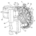
特定の実施の形態では、試料分配モジュールは、例えば回転ドラム形状の移動デバイスを備え、それは一以上の均質化容器を収納可能であり、それは使用される容器を固体又は液体試料、又は懸濁液中の保有された粒子を有するフィルターを受け入れるためにフィードホッパーの下に配置させる。試料が均質化チャンバー中に導入されると、ドラムは、試料処理を開始するためにラックを移動する試料処理モジュールと直線上に容器を位置するまで再度回転する。 In a particular embodiment, the sample distribution module comprises a moving device, for example in the form of a rotating drum, which can contain one or more homogenization containers, which can be used as solid or liquid samples, or suspensions. Place under the feed hopper to accept the filter with the retained particles in it. As the sample is introduced into the homogenization chamber, the drum rotates again until the container is positioned in line with the sample processing module moving the rack to initiate sample processing.
移動デバイス又は回転ドラムは、それらの回転能力を備えた垂直又は水平シャフトに組み付けてもよい。 The moving device or rotating drum may be assembled on a vertical or horizontal shaft with their rotational capability.
6.−試料分配コントローラー
試料分配コントローラーは、試料分配モジュール中に導入される試料を適切に分配するために、メカニズム、センサー及び電気機械的なアクチュエーターを制御することに関する。
6). Sample distribution controller The sample distribution controller relates to controlling the mechanisms, sensors and electromechanical actuators in order to properly distribute the sample introduced into the sample distribution module.
試料分配制御モジュールは、全体制御モジュールによって作動され、事前にプログラム化された機能を実行し、その機能が終了したときに、その実行中のエラーが検出されたときと同様に、電気、アナログ又はデジタル信号を全体制御モジュールに送信する。 The sample distribution control module is actuated by the global control module and executes a pre-programmed function, and when that function is finished, as well as when an error in execution is detected, electrical, analog or Send the digital signal to the overall control module.
5欄に示された特定の実施の形態では、それは、ドラム位置を特定する対応するセンサーを用いて、回転ドラムを回転するモーターを制御することに関する。
In the particular embodiment shown in
7.−試料ホモジナイザーモジュール
試料ホモジナイザーモジュールは、均質化を生成するように試料に作用可能であるデバイスで構成されている。前述のデバイスは、グラインダー及び振動デバイスのような機械的な作用のもの、熱的な作用のもの(抵抗など)、又は波形発生デバイス(超音波など)が可能である。前述のデバイスは、緩やかな混和から、いくつかの微生物の胞子と同じくらい抵抗力がある細胞(溶解)の破砕を引き起こすまで、前述の試料の攪拌及び均質化の程度を規制することが可能である。
7). Sample homogenizer module The sample homogenizer module consists of a device that can act on the sample to produce a homogenization. The aforementioned devices can be mechanically actuated, such as grinders and vibratory devices, thermally actuated (such as resistance), or waveform generating devices (such as ultrasound). The device described above can regulate the degree of agitation and homogenization of the sample from gentle mixing to causing disruption of cells (lysis) as resistant as some microbial spores. is there.
次のように試料均質化モジュールの特定の実施の形態は特定される。 Specific embodiments of the sample homogenization module are specified as follows.
1.本発明の特定の実施の形態では、試料ホモジナイザーモジュールは、ホモジナイザーコントローラーによって供給される高周波数の電力を縦振動に変換する超音波発生圧電デバイスによって形成される。そのような振動は、ホーンの自由端を介して増幅され、圧電デバイスにしっかりと取り付けられる。試料ホモジナイザーモジュールは、メイン試料処理モジュールチャンバーを閉じるラック内に収納され、前述のチャンバーを閉じる壁に接触してそれにしっかりと固定される。 1. In a particular embodiment of the present invention, the sample homogenizer module is formed by an ultrasonic generating piezoelectric device that converts high frequency power supplied by a homogenizer controller into longitudinal vibration. Such vibration is amplified through the free end of the horn and is securely attached to the piezoelectric device. The sample homogenizer module is housed in a rack that closes the main sample processing module chamber, and contacts the wall that closes the aforementioned chamber and is firmly fixed thereto.
ホーンからの振動は、粒子物質を分解し、試料中に存在する細胞を溶解し、そして前述の試料を均質化して、次に前述の溶液又は懸濁液中のキャビテーションを引き起こす圧縮波を処理試料を含む溶液又は懸濁液中に発生する。溶解は、液体試料中にマイクロスフィアを導入することによって改善可能である。 The vibration from the horn decomposes the particulate matter, lyses the cells present in the sample, homogenizes the sample, and then processes the compressed wave causing cavitation in the solution or suspension described above. Occurs in a solution or suspension containing Dissolution can be improved by introducing microspheres into the liquid sample.
超音波溶解は、液体中のホーンの直接的、又は米国特許6431476で実行されるような薄膜を介した作用によって実行可能である。 Ultrasonic lysis can be performed either directly on the horn in the liquid or by action through a thin film as performed in US Pat. No. 6,431,476.
試料処理モジュール圧力及び温度センサーは、処理の適切な動作をモニターする。 Sample processing module pressure and temperature sensors monitor the proper operation of the process.
2.本発明の他の特定の実施の形態では、試料ホモジナイザーモジュールは、機械的なブレード又はピストンホモジナイザーによって形成される。液体中のブレード又はピストンの機械的な作用及び壁との摩擦は、均質化さらに溶解さえ許容する。均質化の改善は研磨剤の添加によって可能である。 2. In another particular embodiment of the invention, the sample homogenizer module is formed by a mechanical blade or a piston homogenizer. The mechanical action of the blades or pistons in the liquid and the friction with the walls allow homogenization and even dissolution. Homogenization can be improved by adding an abrasive.
8.−試料ホモジナイザーコントローラー
試料ホモジナイザーコントローラーは、試料ホモジナイザーモジュール中に導入される試料を適切に均質化するために必要な電気機械的なメカニズム及びセンサーを制御することに関する。
8). Sample homogenizer controller The sample homogenizer controller relates to controlling the electromechanical mechanisms and sensors necessary to properly homogenize the sample introduced into the sample homogenizer module.
試料ホモジナイザー制御モジュールは、全体制御モジュールによって作動され、事前にプログラム化された機能を実行し、その機能が終了したときに、その実行中のエラーが検出されたときと同様に、電気、アナログ又はデジタル信号を全体制御モジュールに送信するものである。 The sample homogenizer control module is activated by the overall control module and executes a pre-programmed function, and when that function is finished, an electrical, analog or analog A digital signal is transmitted to the overall control module.
ポイント7の特定の実施の形態1では、試料ホモジナイザー制御モジュールは、供給システムからの電力を高周波数の電力に変換し、事前に確立された時間シーケンスにしたがって圧電デバイスにそれを送る。さらに、それは、振動での振幅を修正することによってアウトプット電圧を圧電デバイスに調整する。 In particular embodiment 1 of point 7, the sample homogenizer control module converts the power from the delivery system to high frequency power and sends it to the piezoelectric device according to a pre-established time sequence. In addition, it adjusts the output voltage to the piezoelectric device by modifying the amplitude at vibration.
試料ホモジナイザー制御モジュールの7欄の特定の実施の形態2では、ブレード又はピストンを操作する電気機械的なデバイスは、アクティブ/非アクティブでなければならない。 In particular embodiment 2 of column 7 of the sample homogenizer control module, the electromechanical device that operates the blade or piston must be active / inactive.
9.−試料処理モジュール
「試料処理モジュール」は、前述の試料を異なる物理的処理(均質化、溶解、加熱、放射など)、化学的処理(酵素反応のような化学又は生物化学試薬での修飾など)、又は生物学的処理(微生物との相互作用)にさらすことを目的とするデバイスのアセンブリとして定められる。
9. -Sample processing module The "sample processing module" is a different physical processing (homogenization, dissolution, heating, radiation, etc.) and chemical processing (modification with chemical or biochemical reagents such as enzymatic reactions). Or an assembly of devices intended to be exposed to biological treatment (interaction with microorganisms).
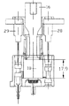
本発明の特定の実施の形態では、試料処理モジュールは、2つの明らかに区別されたサブアセンブリを提供する:試料を均質化チャンバー内に収納する均質化容器と前述のチャンバーを閉じる移動ラックである。 In a particular embodiment of the invention, the sample processing module provides two clearly distinct subassemblies: a homogenization container for storing the sample in a homogenization chamber and a moving rack that closes the aforementioned chamber. .
本発明の特定の実施の形態では、試料処理モジュールは、1からいくつかの均質化容器を含み、少なくとも容器あたり一つの試料の分析を許容する。それぞれの均質化容器は、異なるサイズの導管によってそれに接続されたいくつかの第二のチャンバーによって囲まれた一以上の主な均質化チャンバーを備える。メイン均質化チャンバーは、試料取得モジュールホッパーを介して固体又は液体状態の試料を受けるように開いている。試料の処理の間、この開口は試料処理モジュールを閉じるラックのピストンによって密閉される。均質化容器の第二チャンバーは、シリコンキャップで密閉され、各種区分サイズの導管によってメインチャンバーと通じている。これらの第二チャンバーは、いくつかの試薬を均質化チャンバー中に導入するために使用され、試薬及び溶液管理モジュール排管によって注入される。これらの第二チャンバーハウスのいくつかは、メイン均質化チャンバー中で実行される処理の測定パラメーター(温度、圧力、pH、導電率、など)を調査する。 In certain embodiments of the invention, the sample processing module includes from one to several homogenization vessels, allowing analysis of at least one sample per vessel. Each homogenization vessel comprises one or more main homogenization chambers surrounded by several second chambers connected to it by different sized conduits. The main homogenization chamber is open to receive the solid or liquid sample through the sample acquisition module hopper. During sample processing, this opening is sealed by a rack piston that closes the sample processing module. The second chamber of the homogenization vessel is sealed with a silicon cap and communicates with the main chamber by various sized conduits. These second chambers are used to introduce several reagents into the homogenization chamber and are injected by reagent and solution management module drains. Some of these second chamber houses investigate the measurement parameters (temperature, pressure, pH, conductivity, etc.) of the process performed in the main homogenization chamber.
メインチャンバーの壁は通気ポートを有し、前述のポートがピストンによって、例えば前述のピストンの漏れ止めリングジョイントによって超えられるように、ピストンによる前述のチャンバーの密閉のモーメントを決定する。さらに、このピストンは、チャンバー内の圧力の増加を引き起こすように、密閉された位置からメインチャンバー内に移動する。試料は、メインチャンバー中にこの通気ポートを介して導入可能である。 The wall of the main chamber has a venting port, which determines the moment of sealing of the chamber by the piston, such that the port is exceeded by the piston, for example by a leakage ring joint of the piston. In addition, the piston moves from a sealed position into the main chamber to cause an increase in pressure in the chamber. Samples can be introduced into the main chamber through this vent port.
第二チャンバーは、試薬管理モジュールに属する排管が介されるキャップによって一方側を閉じることができ、試薬管理モジュールによって発生される過剰の圧力によって、均質化モジュールラックの移動によって電気的、機械的に操作される通常のクローズバルブで他方側を閉じることができる。 The second chamber can be closed on one side by a cap through which a drain tube belonging to the reagent management module is passed, and electrically and mechanically by movement of the homogenization module rack due to excessive pressure generated by the reagent management module. The other side can be closed with a normal closing valve operated.
本発明の特定の実施の形態では、それぞれの均質化容器はまたフィルターのシステムと試料アウトレット導管に配置されるバルブとを有する。フィルターは、所望のサイズを超えるサイズを有する固体が反応モジュールにアクセスすることを防止するために使用される。バルブは、均質化容器を反応モジュールと分離又は接続し、処理試料が反応モジュール中に注入される必要があるモーメントを制御することを許容する。 In a particular embodiment of the invention, each homogenization vessel also has a filter system and a valve located in the sample outlet conduit. The filter is used to prevent solids having a size exceeding the desired size from accessing the reaction module. The valve separates or connects the homogenization vessel with the reaction module, allowing the processed sample to control the moment that needs to be injected into the reaction module.
本発明の特定の実施の形態では、試料処理モジュールは均質化チャンバーを閉じる移動ラックを有する第二サブアセンブリを備える。試料処理の間、このサブアセンブリはラックに固定されガスケットに備えられたピストンによって均質化チャンバーの上部部分を密閉する。試料処理モジュール回転ドラムによってラックと直線上である全ての試料処理モジュール容器のために1つの移動ラックがある。ラックは、軸方向に案内され、スクリューナットギア減速とのステッピングモーターによって操作される。それによって、前述のラックは、前述のドラム又は移動デバイスの両端のうち一方側で試料分配モジュールシャフトに組み付けられる。このシステムは、ピストンの軸方向の進行の非常に正確な制御を許容する。次に、移動ラックは、試薬を注入し、試料のパラメーターを測定し、均質化を実行するための正確な位置決めを許容する試薬及び溶液管理モジュール排管及び試料ホモジナイザーモジュール圧電システムを収納する。密閉がなされると、均質化チャンバー内のピストンの進行は、取り扱いされる溶液又は懸濁液中に過剰圧力を発生し、溶液又は懸濁液中にキャビテーションを発生させるために、圧電システムホーンとピストン壁の間の必要な接触を確保する。 In a particular embodiment of the invention, the sample processing module comprises a second subassembly having a moving rack that closes the homogenization chamber. During sample processing, this subassembly seals the upper part of the homogenization chamber with a piston fixed to the rack and provided with a gasket. There is one moving rack for all sample processing module containers that are in line with the rack by the sample processing module rotating drum. The rack is guided in the axial direction and is operated by a stepping motor with screw nut gear reduction. Thereby, the aforementioned rack is assembled to the sample distribution module shaft on one side of both ends of the aforementioned drum or moving device. This system allows very precise control of the axial travel of the piston. The mobile rack then houses reagent and solution management module drains and sample homogenizer module piezoelectric systems that inject reagents, measure sample parameters, and allow accurate positioning to perform homogenization. Once sealed, the progression of the piston in the homogenization chamber creates an overpressure in the solution or suspension being handled, and a piezoelectric system horn to generate cavitation in the solution or suspension. Ensure the necessary contact between the piston walls.
説明された実施の形態では、ピストンが容器を閉じるために組み立てられているラックが垂直軸の回転ドラム上に位置するが、回転ドラムが水平軸を有する場合では、前述のラックは回転ドラムの一方に位置することになり、異なる容器がそれらの他端に配置されてもよい。あらゆる場合では、試料処理モジュール容器のそれぞれは、それらを閉じるための手段を備えることが可能である。これらの手段は、それぞれの容器に組み立てられ均質化モジュール移動ラックの動作によって操作されるピストン又はバルブを有してもよい。 In the described embodiment, the rack in which the piston is assembled to close the container is located on a vertical axis rotating drum, but when the rotating drum has a horizontal axis, the aforementioned rack is one of the rotating drums. Different containers may be placed at their other end. In all cases, each of the sample processing module containers can be provided with means for closing them. These means may comprise pistons or valves that are assembled in respective containers and operated by the operation of a homogenization module mobile rack.
10.−試料反応及び処理コントローラー
試料反応及び処理コントローラーは、試料処理モジュール中に導入される試料を適切に処理し、処理の後にそれらを反応モジュール中に注入するために必要な電気機械的なメカニズムとセンサーを制御することに関する。
10. -Sample reaction and processing controller The sample reaction and processing controller is the electromechanical mechanism and sensor required to properly process samples introduced into the sample processing module and inject them into the reaction module after processing. Related to controlling.
反応処理コントローラーは、全体制御モジュールによって作動され、事前にプログラム化された機能を実行し、その機能が終了するときに、その実行中のエラーが検出されたときと同様に、電気、アナログ又はデジタル信号を全単制御コントローラーへ送信するものである。 The reaction processing controller is activated by the overall control module and executes a pre-programmed function, and when that function is finished, an electrical, analog or digital signal is detected, as well as when an error in execution is detected. The signal is sent to all single control controllers.
9欄に述べられた特定の実施の形態では、反応処理コントローラーは、ラックの位置を確認することに使用されるセンサー及び均質化チャンバーをモニターするものと同様に、均質化容器にラックを位置させる電気機械的な要素を制御することに関する。 In the particular embodiment described in column 9, the reaction process controller positions the rack in the homogenization vessel, similar to the sensor used to confirm the position of the rack and the monitoring of the homogenization chamber. It relates to controlling electromechanical elements.
11.−反応モジュール
「反応モジュール」は、そこに反応チャンバーがある支持体を備えるデバイスとして定められ、メイン導管によって試料処理モジュールと、他の導管によって試薬及び溶解管理モジュールとに接続される。反応チャンバーは、溶液又は懸濁液中に存在する物質(分子から完全な微生物になるもの)を検出することが可能なバイオセンサー又はセンサーシステムを収納する。前述のセンサーシステムは、DNA又はタンパク質マイクロアレイ(バイオチップ)、又はマイクロ流体に基づく他のシステムの形状である少なくとも一つの検出物質を有することが可能である。前述の検出物質は次によって形成されるグループから選択可能である:a)アミノ酸特性の物質;b)タンパク質に関する特性の物質;c)ヌクレオチド特性の物質;d)核酸;e)ペプチド核酸(PNA);f)脂質特性の物質;g)単糖類特性の物質;h)これらのうち少なくとも2つの組合せである物質;j)生きている全細胞;j)胞子の形である全細胞;k)細胞抽出物又は溶解物;l)細胞によって形成される組織;m)全ウィルス又は任意のその成分;n)合成ポリマー及びo)分子インプリントポリマー(MIP)。他の物質と特に結合可能なタンパク質は、モノクローナル又はポリクローナル抗体である可能性がある。さらに、試料修飾化合物は、試料中に存在する検体の任意の一つ、又は前述したこれらの間からの一以上の物質、又はそれらの組合せと結合可能である化学試薬から選択可能である。前述のマイクロアレイは、説明した検出物質の単一のタイプ又は混合物で構成可能である(例えば単一のキャリア中にDNA及びタンパク質ポイントを含むマイクロアレイである)。反応チャンバーは、フローセルのように働くことが可能であり、試料処理モジュールから来る溶液又は懸濁液は、センサー中に存在する検出した物質又は物質群との溶液又は懸濁液中に存在する物質の相互作用を許容するように、前述の反応チャンバーを循環する。バイオセンサー中に保有された試料の信号は、上述したもののうち一以上の物質を含む反応混液又は試料によって増幅可能である。
11. Reaction module A “reaction module” is defined as a device with a support in which a reaction chamber is located, connected to the sample processing module by a main conduit and to the reagent and lysis management module by another conduit. The reaction chamber houses a biosensor or sensor system that can detect substances present in a solution or suspension (from molecules that become complete microorganisms). Such sensor systems can have at least one detection substance in the form of a DNA or protein microarray (biochip), or other system based on microfluidics. The aforementioned detection substances can be selected from the group formed by: a) substances with amino acid characteristics; b) substances with protein properties; c) substances with nucleotide characteristics; d) nucleic acids; e) peptide nucleic acids (PNA) F) substances with lipid characteristics; g) substances with monosaccharide characteristics; h) substances that are a combination of at least two of these; j) whole living cells; j) whole cells in the form of spores; k) cells. Extract or lysate; l) tissue formed by cells; m) whole virus or any component thereof; n) synthetic polymer and o) molecularly imprinted polymer (MIP). Proteins that can bind specifically to other substances can be monoclonal or polyclonal antibodies. Further, the sample modifying compound can be selected from any one of the analytes present in the sample, or a chemical reagent that is capable of binding to one or more of the aforementioned substances, or combinations thereof. Such microarrays can be composed of a single type or mixture of the detection substances described (eg, microarrays containing DNA and protein points in a single carrier). The reaction chamber can act like a flow cell and the solution or suspension coming from the sample processing module is a substance present in solution or suspension with the detected substance or group of substances present in the sensor. The reaction chamber is circulated so as to allow the interaction. The sample signal retained in the biosensor can be amplified by a reaction mixture or sample containing one or more of the above-described substances.
本発明の特定の実施の形態では、溶液又は懸濁液は、試料処理モジュールから反応モジュールまでバルブ、フィルターシステム及びメイン導管を通って循環する。試料が処理されると、反応チャンバーにこのメイン導管を介して入る。この同じチャンバーは、センサー中に存在する検出物質又は物質群と反応すると最終的に試料が落ち着く廃棄物保管所と接続するアウトレット導管を有する。一又はいくつかの付加的な導管が反応チャンバーに試料ホモジナイザーの第二チャンバーから直接的に達する。これらの導管は、反応の読取又は測定を実行する前に、試薬、又は簡単な洗浄溶液を反応チャンバー中に注入することを許容する。 In certain embodiments of the invention, the solution or suspension is circulated through the valve, filter system and main conduit from the sample processing module to the reaction module. As the sample is processed, it enters the reaction chamber via this main conduit. This same chamber has an outlet conduit that connects to a waste repository where the sample eventually settles upon reaction with a detection substance or group of substances present in the sensor. One or several additional conduits reach the reaction chamber directly from the second chamber of the sample homogenizer. These conduits allow reagents or simple wash solutions to be injected into the reaction chamber prior to performing a reaction reading or measurement.
特定の実施の形態では、溶液又は懸濁液が均質化されると、それは前述の溶液又は懸濁液中に存在する物質(分子から全微生物)に組み入れ(共有、イオン、疎水又はその他のタイプの結合によるもので)可能である蛍光試薬との反応をなす。前述の蛍光試薬が組み入れられると、反応に至らなかったその余剰分がその引き続く反応を防止する不活性物質によって不活性化される。前述の不活性物質は、蛍光試薬との反応性がある余剰の官能基(例えばアミノ基、カルボキシル基、スルフヒドリル基又はその他の基)に寄与する化学ブロック試薬でもよい。非活性の蛍光試薬の余剰が非活性化されると、試料はフィルターされ、反応チャンバー中に連続的又は不連続的に注入される。その反応チャンバーへの通路は物質を検出するセンサーとの相互作用を許容する。反応が起こると、センサー中に保有されていないマークされた試料の余剰が反応チャンバーの引き続く洗浄によって除去される。洗浄液は廃棄物保管所中に保管される。 In certain embodiments, once the solution or suspension is homogenized, it is incorporated (covalent, ionic, hydrophobic or other types) into the substances (molecules to whole microorganisms) present in the aforementioned solution or suspension. Reaction with a fluorescent reagent that is possible). When the aforementioned fluorescent reagent is incorporated, the excess that did not result in the reaction is inactivated by an inactive substance that prevents the subsequent reaction. The aforementioned inert substance may be a chemical blocking reagent that contributes to an excess functional group (for example, an amino group, a carboxyl group, a sulfhydryl group, or other group) that is reactive with the fluorescent reagent. When the surplus of inactive fluorescent reagent is deactivated, the sample is filtered and injected continuously or discontinuously into the reaction chamber. The passage to the reaction chamber allows interaction with a sensor that detects the substance. When the reaction occurs, the excess of the marked sample that is not retained in the sensor is removed by subsequent washing of the reaction chamber. Cleaning fluid is stored in a waste repository.
本発明の他の特定の実施の形態では、センサー中に保管された試料の信号は、蛍光物質、金属化合物又は酵素でマークされた一以上の物質(DNA、抗体、PNAなど)を含む反応混液によって増幅される。センサーと反応していない余剰の試料が洗浄されると、前述の反応混液は、反応チャンバー中に注入されるまで、試料処理モジュール第二チャンバーのうち一つに保管される。適切な培養時間の後に、保有されていない前述の反応混液の余剰は、洗浄溶液とともに除去される。 In another particular embodiment of the invention, the sample signal stored in the sensor comprises a reaction mixture comprising one or more substances (DNA, antibodies, PNA, etc.) marked with a fluorescent substance, a metal compound or an enzyme. Is amplified by. When the excess sample that has not reacted with the sensor is washed, the aforementioned reaction mixture is stored in one of the second chambers of the sample processing module until it is injected into the reaction chamber. After an appropriate incubation time, any excess of the reaction mixture that is not retained is removed with the wash solution.
異なる反応モジュールチャンバーは、移動デバイス中、例えば分配モジュール移動ドラム中に組み込まれるものである。 The different reaction module chambers are those incorporated in the transfer device, for example in the distribution module transfer drum.
12.−試薬及び溶液管理モジュール
「試薬及び溶液管理モジュール」は、異なる試料処理ステップ:均質化、修飾、反応、洗浄などに関する異なる溶液及び試薬を必要時間で保管し正確に分配するためのデバイス群のアセンブリとして定められる。
12 -Reagent and solution management module "Reagent and solution management module" is an assembly of devices to store and accurately distribute different solutions and reagents in different time required for homogenization, modification, reaction, washing, etc. It is determined as
本発明の特定の実施の形態では、試薬及び溶液管理モジュールのメイン要素は、流動体の保管を実行し、機能を分配するモーター付きのシリンジで構成される。モジュールは、異なる試薬の必要性に応じて同じ数の同一のモーター付きのシリンジのアセンブリを備える。それぞれのアセンブリは次の要素を組み入れる。 In a particular embodiment of the invention, the main element of the reagent and solution management module consists of a motorized syringe that performs fluid storage and distributes functions. The module comprises an assembly of the same number of identical motorized syringes for different reagent needs. Each assembly incorporates the following elements:
1.モジュールラックに固定され、分析される試料の数に応じた能力があるシリンジ。 1. A syringe that is fixed to the module rack and has the ability to accommodate the number of samples to be analyzed.
2.シリンジプランジャロッドを作動するステッピングモーターを備えた線形アクチュエーター。アクチュエーターは、これらが機能的な処理によって定められる異なる圧力である場合に、対応するチャンバー中に流体を正確に注入可能であるように設計される。 2. Linear actuator with a stepper motor that operates the syringe plunger rod. Actuators are designed to be able to accurately inject fluid into the corresponding chamber when they are at different pressures determined by functional processing.
3.シリンジプランジャの位置を決定し、アセンブリの開ループ(「行程端」)又は閉ループ(「エンコーダー」)制御を許容する位置センサー。 3. A position sensor that determines the position of the syringe plunger and allows open loop ("end of stroke") or closed loop ("encoder") control of the assembly.
4.シリンジが作動されないときに流体回路中の圧力バリアを維持するパッシブ(逆止め)又はアクティブ(電動)バルブ。 4). A passive (non-return) or active (motorized) valve that maintains a pressure barrier in the fluid circuit when the syringe is not activated.
5.モジュールの最後の要素として、排管が均質化容器側のチャンバーのシールを通じて貫通する。排管は試料処理モジュール移動ラックに固定され、したがって、その貫通動作は前述のラックの前方移動と同調する。 5. As the last element of the module, a drain tube passes through the chamber seal on the homogenization vessel side. The evacuation tube is fixed to the sample processing module moving rack, and therefore its penetrating action is synchronized with the forward movement of the rack.
6.流体回路を形成する異なる構成要素を接続するために必要な全ての導管とアクセサリー。 6). All the conduits and accessories needed to connect the different components that make up the fluid circuit.
本発明の他の特定の実施の形態では、かなりの数の試薬及び/又は溶液によって特徴付けられ、試薬及び溶液管理モジュールは次によって形成される。
・使用される試薬及び/又は溶液と同じ数のいくつかの保管所。
・異なる保管所の流体を吸引しそれらを均質化又は反応チャンバーに分配することが可能である単一のポンプシステム。
・一又はいくつかの分配バルブ、これらの一つはいくつかのインレット通路と一つのアウトレット通路を備え、保管所から均質化又は反応チャンバーまで異なる導管を開く又は閉じることが可能である。
In another particular embodiment of the invention, characterized by a significant number of reagents and / or solutions, the reagent and solution management module is formed by:
Several repositories with the same number of reagents and / or solutions used;
A single pump system that can aspirate fluids from different repositories and homogenize or distribute them to the reaction chamber.
One or several distribution valves, one of which comprises several inlet passages and one outlet passage, which can open or close different conduits from the storage to the homogenization or reaction chamber.
この試薬及び溶液管理モジュールの構成は、必要とされるアクチュエーターの数と注入通路の数を最大限に簡略化する。 This reagent and solution management module configuration maximizes the number of actuators and injection passages required.
本発明の他の実施の形態では、かなりの数の試薬及び/又は溶液によって特徴付けられ、試薬及び溶液管理モジュールは次によって形成される。
・いくつかの漏れ止めシリンジ−保管所、使用される試薬及び/又は溶液と同じ数であり、ロッドではなくプランジャを備え、シリンジ−保管所を2つのシールされた区画中に分ける:一つは試薬又は溶液用の逆止めバルブを備え、他は推進流体用のインレット通路を備える。
・前述の流体を保管所から吸引しシリンジ−保管所の異なるシールされた区画にそれを分配可能でありこのようにしてそれらのプランジャを作動することが可能な単一のポンプシステムによって形成される閉推進流体回路。
・推進流体回路中の一又はいくつかの分配バルブ、これらの一つは作動されるシリンジ−保管所を選択することを許容するいくつかのアウトレット通路と一つのインレット通路を備える。
・逆止めバルブ及び排管を備えたそれぞれのシリンジ−保管所用の独立したアウトレット及び注入通路。
・前述のポイントの代わりとして、一又はいくつかの分配バルブを介してそれぞれのシリンジ−保管所のアウトレット通路と接続される逆止めバルブ及び排管を備えた一般的な注入通路。
In another embodiment of the invention, characterized by a significant number of reagents and / or solutions, the reagent and solution management module is formed by:
Several leak-proof syringes-repositories, the same number as the reagents and / or solutions used, with plungers rather than rods, dividing the syringe-repositories into two sealed compartments: A check valve for the reagent or solution is provided, and the other has an inlet passage for the propelling fluid.
Formed by a single pump system capable of aspirating the aforementioned fluid from the repository and dispensing it to different sealed compartments of the syringe-repository and thus actuating their plungers Closed propulsion fluid circuit.
One or several distribution valves in the propulsion fluid circuit, one of which comprises several outlet passages and one inlet passage allowing to select the syringe-depot to be activated.
-Each syringe with check valve and drain-independent outlet and injection passage for the repository.
A general injection passage with a check valve and a drain connected to the outlet passage of each syringe-storage via one or several dispensing valves as an alternative to the above points.
この試薬及び溶液管理モジュールの構成は、アクチュエーターの必要な数を最大限に簡略化し、独立した通路を介して、又は選択的に流体の互換性がこれを許容するなら単一の通路を介して試薬/溶液の注入を許容する。 This reagent and solution management module configuration maximizes the required number of actuators to the maximum and either through independent passages, or optionally through a single passage if fluid compatibility allows this. Allow reagent / solution injection.
13.−試薬及び溶液管理コントローラー
試薬及び溶液管理コントローラーは、異なる試料処理ステップに関する異なる溶液及び試薬を必要な時間で保管し正確に分配するために必要な電気機械的なメカニズム及びセンサーを制御することに関する。
13. Reagent and solution management controller The reagent and solution management controller relates to controlling the electromechanical mechanisms and sensors required to store and accurately dispense different solutions and reagents for different sample processing steps at the required time.
試薬及び溶液管理モジュールコントローラーは全体制御モジュールによって作動され、事前にプログラム化された機能を実行し、その機能が終了したときに、その実行中のエラーが検出されたときと同様に、電気、アナログ又はデジタル信号を全体制御モジュールに送信するものである。 The reagent and solution management module controller is activated by the overall control module and executes pre-programmed functions, and when that function is finished, an electrical, analog, as well as when an error in execution is detected Alternatively, a digital signal is transmitted to the overall control module.
12欄に示される第一の特定の実施の形態では、試薬及び溶液管理モジュールコントローラーは、シリンジを移動するアクチュエーターを制御することに関する。プランジャの位置を決定するセンサーを制御するとともに、圧力バリアを維持する電気バルブに作用するためである(12欄に示される実施の形態のポイント14を参照)。
In the first particular embodiment, shown in
14.−データー読取モジュール
「データー読取モジュール」は、反応チャンバー中に発生する反応を検出し検出された信号を適切に処理することを許容するデバイス群のアセンブリとして定められる。
14 Data reading module A “data reading module” is defined as an assembly of devices that allows the detection of reactions occurring in the reaction chamber and allows the detected signals to be processed appropriately.
本発明の特定の実施の形態では、反応ディテクターは、反応の結果として生成される電磁放射周波数のみを読み取るために必要な光学系とフィルターを備えた高解像度で高検出感度のCCDである。前述の電磁放射は、反応処理に関する反応性のある物質(蛍光分子)にエネルギーを与えることで生成される。前述の反応性のある物質のエネルギー化は、レーザーダイオードからの単色光ビームで達成される。CCD読取は、反応チャンバーと反対であり、レーザー光ビームは反射がCCDリーダを照射することを防止するためにある角度で反応チャンバーを照射する。 In a particular embodiment of the present invention, the reaction detector is a high resolution, high detection sensitivity CCD with the optics and filters necessary to read only the electromagnetic radiation frequency generated as a result of the reaction. The aforementioned electromagnetic radiation is generated by applying energy to a reactive substance (fluorescent molecule) related to the reaction process. Energization of the aforementioned reactive material is achieved with a monochromatic light beam from a laser diode. CCD reading is the opposite of the reaction chamber, and the laser light beam illuminates the reaction chamber at an angle to prevent reflections from illuminating the CCD reader.
単一光は、導波管の外表面に形成されるエバネセントモードの結果としてエネルギー化されるバイオセンサーがある導波管によって案内可能である。 A single light can be guided by a waveguide with a biosensor that is energized as a result of the evanescent mode formed on the outer surface of the waveguide.
15.−データー読取コントローラー
データー読取コントローラーは、反応チャンバー中に発生する反応を検出するために使用されるデバイスを制御することに関する。
15. Data read controller The data read controller relates to controlling the device used to detect the reaction occurring in the reaction chamber.
データー読取制御モジュールは、全体制御モジュールによって作動し、事前にプログラム化された機能を実行し、その機能が終了するときに、その実行中のエラーが検出されたときと同様に、電気、アナログ又はデジタル信号を全体制御モジュールに送信するものである。 The data reading control module is operated by the overall control module, performs a pre-programmed function, and when that function is finished, as well as when an error in execution is detected, electrical, analog or A digital signal is transmitted to the overall control module.
14欄に示される特定の実施の形態では、データー読取制御モジュールは、チャンバーから受け取る情報を読み出し、適切にそれを処理し(フィルタリング、活性化領域の同定、活性化領域の定量、など)、引き続いてそれを全体制御モジュールへ移送する間と同様に、事前に設定された時間の間も、レーザーを作動することに関する。
In the particular embodiment shown in
本発明の装置及び方法の特徴及び利点は、図面を参照して以下のように説明されることで、理解されるものである。なお、以下の説明は実施の形態を限定するものではない。 The features and advantages of the apparatus and method of the present invention will be understood from the following description with reference to the drawings. The following description does not limit the embodiment.
図面に示される装置は、土壌又は下層土(subsoil)中に存在するバイオマーカー(生体起源の有機分子及び巨大分子)の検出を許容するロボット化された機器を有する。そのようなバイオマーカーを検出し特徴付ける方法としては、固体支持体(チップ又はマイクロアレイと称する)の特定の位置に固定化される特定の抗体の配列とのそれらの相互作用に基づく。 The device shown in the drawing has a robotized instrument that allows the detection of biomarkers (organic molecules and macromolecules of biological origin) present in the soil or subsoil. Methods for detecting and characterizing such biomarkers are based on their interaction with specific antibody sequences immobilized at specific locations on a solid support (referred to as a chip or microarray).
この装置は、実験を自動的に実行するために必要な全てのメカニズム、ディテクター及びエレクトロニクスを有する。使用される構成要素は、環境条件下の機能に対し、主に市販品であり、設計され、及び/又は選択される。 This device has all the mechanisms, detectors and electronics necessary to perform the experiment automatically. The components used are mainly commercial products, designed and / or selected for function under environmental conditions.
本発明の装置を構成する異なるモジュールは、異なる構成要素及びそれらの動作の同定を簡単にすることを目的として、以下で説明される。 The different modules that make up the apparatus of the present invention are described below for the purpose of simplifying the identification of the different components and their operation.
図1から14に示される例では、装置は試料取得モジュールを欠いており、分析される試料は手動で導入される。これは、装置が対応する取得モジュールコントローラーを欠いているからである。 In the example shown in FIGS. 1-14, the device lacks a sample acquisition module and the sample to be analyzed is introduced manually. This is because the device lacks a corresponding acquisition module controller.
装置はトップカバー1、ボトムカバー2及び一連の中間フレーム3で構成されるラックを有する。このラックは、異なるモジュール群の組み立て用の骨格として機能する。 The apparatus has a rack composed of a top cover 1, a bottom cover 2 and a series of intermediate frames 3. This rack functions as a framework for assembling different module groups.
試料取得モジュールは円筒状ホッパー4(図4参照)を有し、この円筒状ホッパー4は、ラックのトップカバー1に固定され、円錐形の開口を備え、その開口を通じて、約250mgの塊で<0.5mmの粒子サイズの土壌試料が導入される。ホッパーの底部端は内側円錐部4’を備え、この機能としては容器の底部に試料を分配するものであり、後述するように、試料処理モジュールに属する。ホッパー4は、固定又は移動アダプターと置換されてもよい。さらに、試料分配モジュールは、オペレーターによって、又はマルチウェルプレートに保有された試料の注入器によって手動で送り込まれてもよい。
The sample acquisition module has a cylindrical hopper 4 (see FIG. 4), which is fixed to the top cover 1 of the rack and has a conical opening through which a mass of about 250 mg < A soil sample with a particle size of 0.5 mm is introduced. The bottom end of the hopper is provided with an inner conical portion 4 ', which serves to distribute the sample to the bottom of the container and belongs to the sample processing module as will be described later. The
試料分配モジュールは、試料処理及び反応モジュールの構成要素を支持し、収納し及び位置を正し、そして、2つのフランジで構成される陽極酸化アルミニウムからなる回転ドラムによって主に形成される。トップフランジ5(図4参照)は12の試料処理モジュール容器6を収納し、ボトムフランジ7は反応モジュール要素を固定するためのデバイス群を有する。フランジは両方ともそれぞれのアンギュラコンタクトベアリング8上に組み付けられ、それらの付属ネジによってわずかに予圧されている。ベアリングは、ラックの中央シャフト9に組み付けられており、前述のシャフトについてドラムの回転を許容する。
The sample distribution module supports and houses the components of the sample processing and reaction module, and is mainly formed by a rotating drum made of anodized aluminum composed of two flanges. The top flange 5 (see FIG. 4) accommodates twelve sample
ドラムの回転はステッピングモーター10によって実行され、それはモーターシャフトに固定されたピニオン11、及びドラムの底部フランジ7にネジ締めされたホイール12で構成されるギア電動装置を介して、ラックのボトムカバー2にネジ締めされる。モーターは1.8°/ステップの分解能を有し、0.16Nmのトルクを供給することが可能である。ギア電動装置の比は、i=5:1であり、回転ドラムの最終的な分解能は、0.36°/ステップであり、試料処理モジュール容器の軸の円周方向の変位量で0.45mm/ステップの解像度を許容する。
The rotation of the drum is carried out by a stepping
ドラムに付属した表示器14がセンサーレーザービームと干渉するときに、回転ドラムの初期位置はラックのフレーム3に固定された光学センサー13によって決定される。
When the
試料ホモジナイザーモジュールは、市販のコンバーター15(図4参照)によって形成される超音波圧電デバイス及びコンバーターの端部に堅くネジ締めされるホーン16を有する。
The sample homogenizer module has an ultrasonic piezoelectric device formed by a commercially available converter 15 (see FIG. 4) and a
コンバーター15は円筒状形状(φ32mm、長さ=89mm)であり、40kHzの周波数で電圧が加えられる。
The
ホーン(φ16mm、長さ=49mm)は、チタン(Ti 6Al 4V)からなり、円滑な移行によって取り付けられた円筒状部分によって形成される。ホーンの自由端は、試料処理モジュールの均質化チャンバーを閉じる壁に接触する平面の円形のフランジ(φ12.2mm)で終端する。 The horn (φ16 mm, length = 49 mm) is made of titanium (Ti 6Al 4V) and is formed by a cylindrical part attached by a smooth transition. The free end of the horn terminates with a flat circular flange (φ12.2 mm) that contacts the wall that closes the homogenization chamber of the sample processing module.
このアセンブリは、試料処理モジュールメインチャンバーを閉じる縦方向に移動するラック17内に収納され、コンバーター15の円筒状ケーシングを支えるクランプ17’によってそれに堅く固定される。
This assembly is housed in a
コンバーターは、試料ホモジナイザー制御モジュールによって供給される高周波数の電力をホーンの自由端によって増幅される縦方向の振動に変換する。ホーンの振動は、順に、処理試料溶液中に圧力波を発生させ、それは溶液中にキャビテーションを引き起こし、試料を均質化する。キャビテーションの強度、及びそれに従って混合物の均質化の程度は、振動の振幅を選択することで調整可能であり、低振幅のための緩やかな均質化から高振幅レベルのための細胞の破砕までの範囲をカバー可能である。 The converter converts the high frequency power supplied by the sample homogenizer control module into longitudinal vibration that is amplified by the free end of the horn. The vibration of the horn in turn generates a pressure wave in the treated sample solution, which causes cavitation in the solution and homogenizes the sample. The intensity of cavitation, and accordingly the degree of homogenization of the mixture, can be adjusted by selecting the amplitude of vibration, ranging from gentle homogenization for low amplitudes to cell disruption for high amplitude levels Can be covered.
試料ホモジナイザー制御モジュールはコンバーターを制御し、ホーンの端部で生じる抵抗にしたがって、供給パワーを増加又は減少させることで、事前に選択される振幅を維持することに役立つ。デバイスは、130wの最大出力を供給するように設計される。 The sample homogenizer control module controls the converter and helps maintain a preselected amplitude by increasing or decreasing the supply power according to the resistance generated at the end of the horn. The device is designed to provide a maximum output of 130w.
試料処理モジュールは2つの明らかに区別されるサブアセンブリ(図4から6参照)を備える:
−均質化容器6及び均質化チャンバーを閉じる移動ラック17。
−均質化容器6は均質化処理の間に試料分配モジュールによってその中に堆積される試料を収容する。
The sample processing module comprises two clearly distinct subassemblies (see FIGS. 4 to 6):
A moving
The
装置は、12の均質化容器まで収納するように設計され、容器あたり単一の試料の分析を許容する。 The device is designed to accommodate up to 12 homogenized containers, allowing analysis of a single sample per container.
容器は、均質化処理を視認することができるように透明なアクリル樹脂からなる。 The container is made of a transparent acrylic resin so that the homogenization treatment can be visually recognized.
それぞれの容器は、異なるサイズの導管群23によってそれに接続される4つの第二チャンバー19、20、21及び22によって囲まれるメイン均質化チャンバー18を備える。
Each vessel comprises a
円筒状形状の均質化チャンバー18(φ19mm、長さ22mm)は、ホッパー4を介して供給される固体又は液体状態の試料を受け取るために、そのトップ部分が開いている。試料処理の間、この開口は移動ラック17のピストン24によって密閉される。チャンバーの底部はφ10mmのポート25を備え、このポート25を介して均質化混合物が反応モジュール中に注入される。チャンバーの円筒状壁は、チャンバーの底部の上に9.3mmの高さの位置にある不図示のφ0.5mmの通気ポートを備え、これはラックのピストンによって運ばれるガスケット26が前述のポートをシールするときにチャンバーの密閉のモーメントを決める。
The cylindrically shaped homogenization chamber 18 (φ19 mm,
第二チャンバー19から22は、これらの上部及び底部部分の両方において、シリコンキャップ27で密閉され、導管23によってメインチャンバーに通じる。容器は次の第二チャンバーを有する。
The
蛍光マーカーチャンバー22:これはφ1mmの導管23を介してメインチャンバーに取り付けられる円筒状チャンバー(サイズ=φ4×7mm)である。それは、チャンバーの底部に付着した1mgの蛍光マーカー化合物を固体状態で収納する。このチャンバーは、1mlの試料溶液を準備するために必要な試薬及び溶液管理モジュール排管28を介して食塩水を注入するために使用される。食塩水の注入の間、蛍光マーカーは溶解され、均質化チャンバー18中に導入され、試料溶液の部分を形成する。
Fluorescent marker chamber 22: This is a cylindrical chamber (size = φ4 × 7 mm) attached to the main chamber via a
ブロッキング試薬チャンバー21:これは円筒状チャンバー(サイズ=φ4×4mm)であり、φ1mmの導管23を介してメインチャンバーに取り付けられる。このチャンバーは、試料の分子と反応しなかった蛍光マーカーの余剰分をブロッキングするために必要な試薬及び溶解管理モジュール排管29を介してBSAブロッカー溶液を注入するために使用される。このチャンバーのボトムキャップ27の下に配置される円錐形状ポートがあり、この円錐形状ポートには導管を洗浄する反応モジュールのLuerカップリング28’が収納される。
Blocking reagent chamber 21: This is a cylindrical chamber (size = φ4 × 4 mm), which is attached to the main chamber via a
圧力センサーチャンバー20:これは円筒状チャンバー(サイズ=φ4×5mm)であり、その中への溶解の入口を簡単にすることを目的として、φ4mmの幅広い導管23を介してメインチャンバーに取り付けられる。均質化処理の間、このチャンバーは移動ラック17によって運ばれる排管29’を収納する。この排管29’は処理の異なる圧力をモニターすることに関する圧力センサーに接続される。
Pressure sensor chamber 20: This is a cylindrical chamber (size = φ4 × 5 mm) and is attached to the main chamber via a
温度センサーチャンバー19:これは圧力センサーチャンバーと同一であるチャンバーである。均質化処理の間、このチャンバーは、前述の処理の間に試料溶液温度をモニターすることに関して、温度センサープローブ32を順に収納する移動ラック17によって運ばれる排管31を収納する。
Temperature sensor chamber 19: This is the same chamber as the pressure sensor chamber. During the homogenization process, this chamber houses a
センサーチャンバー19及び20の底部と均質化チャンバー18の底部の表面は、溶液の前述の第二チャンバー中への侵入を簡単にするように界面活性剤で処理される。
The bottom surfaces of the
それぞれの均質化容器は、φ12mmのフィルター33を備え、所望のサイズを上回るサイズを有する固体が反応モジュールにアクセスすることを防止するために使用される20μmの径の孔を備える。フィルターは、フィルターホルダー34に配置され、ネジ式のキャップ35内に収納される。このアセンブリは、均質化チャンバーのアウトレットポートの下で、容器の底面にネジ締めされる。ガスケット36はアセンブリの必要な漏れ止めを提供する。
Each homogenization vessel is equipped with a
ネジ式のキャップ35は、逆止めバルブ37が接続される雄Luer円錐を備える。このバルブは均質化容器18を反応モジュールに接続する。バルブは、反応モジュールに存在する1.3バールの過剰圧力のために通常閉じ、両方のモジュールを隔離している。常時閉の電気的に作動するバルブ、又は均質化モジュールラックの移動によって機械的に作動されるものが、逆止めバルブ37に変わって配置されてもよい。
The screw-
図4の均質化チャンバーを閉じる移動ラック17は、試料処理の間、均質化チャンバー18のトップ部分の密閉を実行する。
A moving
試料分配モジュールの回転ドラムによってラックと直線上にある全てのモジュール容器のために一つの移動ラックがある。 There is one moving rack for all module containers that are in line with the rack by the rotating drum of the sample distribution module.
サブアセンブリはアルミニウムからなるラック17を有し、異なるサブアセンブリ構成要素を収納する。それは、試料ホモジナイザーモジュールのコンバーター15を固定するためのトップフランジ38を備える。ボトムフランジ39は、順に、ピストン24と、試薬及び溶液管理モジュール排管28及び29と、圧力及び温度センサー排管29及び31をそれぞれ収納する。
The subassembly has a
ラックは2つのブッシング39によってシャフト9にそってスライドし、フレーム40の中央リブに沿って軸方向にガイドされる。
The rack slides along the shaft 9 by two
ラックの軸方向の移動は、モーターシャフトに固定されたネジ42及び移動ラック17の本体に収納されたナット43の伝達装置を介して、ラックのトップカバー1にネジ締めされたステッピングモーター41によって実行される。モーターは1.8°/ステップの分解能であり、0.16Nmのトルクを供給することが可能である。ネジはM6×1のネジ山を備え、ラック移動の最終的な分解能は5μm/ステップであり、前述の移動のとても正確な制御を許容し、次に試薬の注入、試料パラメーターの測定及び超音波均質化の性能のために正確な位置になる。
The rack is moved in the axial direction by a stepping
ラックの底部フランジに組み付けられた表示器45がセンサー光ビームに干渉するときに、最終的な移動ラック位置がラックのフレーム40に固定された光学センサー44によって決定される。
When the
図5のピストン24は、ステンレス鋼からなり、トップフランジを備える空洞回転部分であり、トップフランジとともにそれは移動ラックに固定される。底部端は円錐部で終端し、ガスケット26を備えるスレッドブッシング46をそれらに組み付ける。どちらの部分もともにネジ締めされ、ブッシング46の内側円錐部によって発生される圧力によって膜をしっかりと固定する。膜47はPTFEからなり、0.1mmの厚みである。ピストンの内側は、膜47に負担を掛ける試料ホモジナイザーモジュールホーン16を収納する。このアセンブリは、均質化チャンバーのトップ開口を密閉し、結果として漏れ止めがガスケット26と膜47によってなされる。均質化チャンバー内のピストン24の前方方向の移動は、それらの密閉が一度なされると、取り扱われる溶液中に過剰圧力を生成し、溶液中のキャビテーションを生成するために圧電システムホーン16とピストンの膜47の間の必要な接触を確実にする。
5 is a hollow rotating part made of stainless steel and provided with a top flange, and together with the top flange, it is fixed to a moving rack. The bottom end terminates in a cone and a
圧力センサー30は、均質化チャンバーの過剰圧力をモニターする。ホイートストーンブリッジに基づき、その主な特徴としては次のようになる。
・測定範囲:0÷207kPa
・印加電圧:10V
・総アウトプット信号:100mV
・アウトプット信号感度:0.483mV/kPa
The
・ Measurement range: 0 ÷ 207kPa
・ Applied voltage: 10V
・ Total output signal: 100mV
Output signal sensitivity: 0.483 mV / kPa
チャンバー内の過剰圧力パラメーターは、ピストン−ホモジナイザーアセンブリの均質化位置を制御し定めるために使用される。チャンバー内の過剰圧力が0.8barの値に達するときに、反応及び処理コントローラーは移動ラックのモーター41を抑制する。それは、均質化時間を制御し定めるためにも使用される。チャンバー内の過剰圧力が1.0barの値を超えるときに、試料ホモジナイザー制御モジュールは、圧電システムコンバーター15を抑制する。
The overpressure parameter in the chamber is used to control and define the homogenization position of the piston-homogenizer assembly. When the overpressure in the chamber reaches a value of 0.8 bar, the reaction and processing controller will inhibit the
温度センサー32は、均質化処理の間、試料溶液の温度をモニターする。それは、φ0.5mm及び長さ250mmのステンレス鋼のさや内に収納されるK−タイプの熱電対を備えるプローブに基づく。このプローブは、ネジ式の止め金具によって装置のトップカバー1に固定され、その自由端は排管31内に導入され、これはシリコンキャップ27を介してプローブの進入を簡単にする。
The
試料溶液温度パラメーターは、均質化時間を制御し定めるために使用される。溶液温度が所定の臨界値を超えるときに、試料ホモジナイザー制御モジュールは圧電システムコンバーター15を抑制する。
The sample solution temperature parameter is used to control and define the homogenization time. The sample homogenizer control module inhibits the
反応モジュール(図5から図7参照)は平行管の支持体50(サイズ:76×26×6,5mm)を有し、この支持体50には、0.3mmの深さで、左右対称の不規則な六角形の形状(全体の寸法:14×8mm)を有する反応モジュールと呼ばれる開口した空洞51がある。このチャンバーは、次のアクセス通路を備える。
The reaction module (see FIGS. 5 to 7) has a parallel tube support 50 (size: 76 × 26 × 6, 5 mm), which is 0.3 mm deep and symmetrical. There is an
・均質化溶液又は懸濁液インレット通路52。これはチャンバーのトップの角にあり、φ1mmの導管によって形成され、試料処理モジュール75と逆止めバルブ37との漏れ止め接合のためにメスLuer円錐部で終端する。
• Homogenizing solution or
・洗浄溶液インレット通路53。チャンバーのトップの角に配置し、洗浄導管28’の漏れ止め接続のためにφ2.5mmの導管によって形成される。
A cleaning
・溶液アウトレット通路54。チャンバーの底部の角に配置し、φ2mmの導管によって形成され、廃棄物保管所57との漏れ止め接続のためにメスLuer円錐部で終端する。
A
・インレットポート52及び53とアウトレットポート54はポンプシステムを備える導管によって接続可能であり、詳述しないが、それはバイオセンサーの試料の再循環を許容する。チャンバー51は、バイオセンサー操作を改善するために液体試料を攪拌又は移動するためのシステムをさらに有してよい。
反応チャンバー51は、異なる流体の循環を改善することを目的として、疎水性の試薬SIGMACOTEの薄いコーティングを有し、その表面に固体粒子及び分子が接着することを防止する。
The
反応チャンバー51及びそのアクセス通路はガラススライド55(サイズ:75×25×1mm)によって閉じられ、その内側では、チャンバーとともに内側に収納されて、分子から全微生物まで、均質化溶液中に存在する物質を検出可能なバイオセンサー又はセンサーシステム56が保管される。このセンサーシステムは、マイクロアレイ形状で異なる検出物質で構成される。
The
スライド55は2つのクリップ50’によって支持体50に固定される。接着の漏れ止めは、長方形のCV−1152シリコン縁によって確実にされ、このシリコン縁は、支持体50の反対側に配置される2つのポートを介して注入される。シリコンが一度固まると、それは、反応モジュールとそのアクセス通路の周囲の1×1mmの区分を有するシーリングガスケットを形成する。
The
洗浄導管28’は内周直径1.6mmで長さ約90mmのプラスチックパイプによって形成される。それは金属結合でその開口端に備えられ、オスLuer円錐体で終端し、ブロッキング試薬チャンバー下の均質化容器18のハウジング内に密閉されて接続される。それは、反応モジュール洗浄通路との漏れ止め接続のために底部端に結合した湾曲したプラスチックを有する。
The cleaning conduit 28 'is formed by a plastic pipe having an inner diameter of 1.6 mm and a length of about 90 mm. It is provided with a metal bond at its open end, terminates in a male Luer cone, and is sealed and connected within the housing of the
廃棄物保管所57は反応チャンバーアウトレット通路に接続される偏心オスLuer円錐体を備える5mlの容量のプラスチックシリンジによって形成される。シリンジはプランジャを欠いており、そのトップ開口を密閉する代わりのシリコンキャップ58を有する。
The
廃棄物保管所57は全ての反応モジュールに共通とし、スライドラックに組み付けられた排管によってそれらのアウトレットに接続されることが可能である。
A
アセンブリは、流体回路を視認可能なように、透明な材料(ガラス、アクリル、など)で作製される。 The assembly is made of a transparent material (glass, acrylic, etc.) so that the fluid circuit is visible.
チャンバー18が組み立てられ、試料処理モジュール均質化容器6にそのアクセス通路とともに接続されると、導管及び保管所が1.3barの過剰圧力で食塩水であらかじめ満たされた漏れ止め回路を形成する。廃棄物保管所57内の溶液レベルは1mlであり、保管所の残りは前述の過剰圧力で加圧された空気で満たされる。
When the
装置は、12の反応モジュールまで収納するように設計され、モジュールあたり1つの試料の分析を許容する。 The device is designed to accommodate up to 12 reaction modules and allows analysis of one sample per module.
試薬及び溶液管理モジュールは、異なる試料処理ステップに関する異なる溶液及び試薬を、必要な時間で、保有し正確に分配するために必要な全ての構成要素を有する。 The reagent and solution management module has all the components necessary to hold and accurately dispense different solutions and reagents for different sample processing steps at the required time.
試薬及び溶液管理モジュールメイン要素(図1及び図2参照)は、流体の保有及び分配の機能を実行するモーター付きのシリンジ60で構成される。モジュールは、モーター付きのシリンジの2つの同じアセンブリを有し、一つは固体試料を溶解するために使用される食塩水を対象とし、もう一つは次に反応チャンバー洗浄溶液機能を実行するBSAブロッカー溶液を対象とする。流体が試薬管理モジュール中にある場合では、装置はそれらを反応チャンバー内へ注入する機器を有してもよい。
The reagent and solution management module main element (see FIGS. 1 and 2) consists of a
それぞれのアセンブリは次の要素を組み込んでいる。 Each assembly incorporates the following elements:
1.装置の構造のフレーム3にベースプレートを介して固定される市販のモーター付きのシリンジ60(サイズ:203×56×94mm)。その主な構成要素は次になる。 1. A commercially available motorized syringe 60 (size: 203 × 56 × 94 mm) fixed to the frame 3 of the apparatus structure via a base plate. Its main components are as follows.
・ロック閉鎖でオスLuer円錐体を備え10ml容量のシリンジ60。円錐体の端部は、アセンブリのベースプレート62に次いでネジ締めされる支持体61に固定される。プランジャロッドは線形アクチュエーターロッド63にネジ締めされる。
A 10
・シリンジプランジャロッドを作動するステッピングモーター64を備える線形アクチュエーター。このアクチュエーターは89Nの最大の力を発するように設計される。過剰圧力なしで注入されるときに得られる解像度としては10μl/ステップである。
A linear actuator with a stepping
・ベースプレートに収納され、シリンジプランジャの位置を決定し、アセンブリのオープンループコントロールを許容する不図示の光学センサー。 An optical sensor (not shown) that is housed in the base plate, determines the position of the syringe plunger, and allows open-loop control of the assembly.
2.シリンジが作動しないときに流体回路内に圧力バリアを維持する逆止めバルブ65。
2. A
3.不図示のネジ式排管(サイズ:φ1×20mm)、これは、アセンブリの最終的な要素として、均質化容器18の側面チャンバーのシリコンキャップを貫通する。排管は試料処理モジュール移動ラック17に固定され、したがってその貫通移動は前述のラックの前方移動と同調する。
3. A threaded drain (not shown) (size: φ1 × 20 mm), which penetrates the silicon cap of the side chamber of the
4.流体回路を形成する異なる構成要素を接続するために必要な全ての導管及び付属品(サイズ:1/16”)。 4). All the conduits and accessories necessary to connect the different components forming the fluid circuit (size: 1/16 ").
データー読取モジュールは、反応チャンバー内に発生する反応を検出することを許容する構成要素を有する。 The data reading module has components that allow it to detect reactions occurring within the reaction chamber.
それは、レーザーダイオード66(図1及び図4参照)及びCCDカメラ67で主に構成され、両方とも市販品であり、装置の構造のフレーム40にネジ締めされるブラケット68に組み付けられる。
It is mainly composed of a laser diode 66 (see FIGS. 1 and 4) and a
レーザーダイオード66は、反応チャンバー51全体を放射するために、635nmの波長及び十分な幅の単色の光ビームを発射し、蛍光分子をエネルギー化する。それはブラケット68に組み付けられ、光ビームが45°で反応チャンバープレーンを放ち、反射がCCDカメラ軸の方向に発生することを防止する。円筒状のケーシング(サイズ:φ38×158mm)に収納されたレーザーダイオード66は、250mWの最大の力を有し、ダイオードの温度を調整することを許容する冷却システムを有する。
The
CCDカメラ67は、蛍光分子がレーザー光ビームによってエネルギー化されるときに、蛍光分子によって放射される電磁放射を検出する。前述の放射は、マーカーとして使用される蛍光性のdye Cy5の最大放射に対応する670nm中央値のスペクトルバンドを備える。CCD内の他の波長の放射の進入を防止する目的で、カメラは、25mm直径の放射フィルター69である695AF55を備える。焦点しCCD内のイメージを増幅することを許容するレンズ70及びセパレーター71は、デバイスを満たす。3つの構成要素、フィルター、レンズ及びセパレーターは市販品である。
The
カメラは、デジタルで白黒で高解像度で高感度なカメラである。それは次のような特徴を有する。
・サイズ:146×76×64mm
・センサー:1280×1024ピクセルのCCD
・ピクセルサイズ角:6.7×6.7
・センサーサイズ:2/3”
・ダイナミックレンジ:12ビット
・感度:4350e/lux/um2/s
・冷蔵
The camera is a digital, black and white, high resolution, high sensitivity camera. It has the following characteristics.
・ Size: 146 × 76 × 64mm
Sensor: 1280 x 1024 pixel CCD
-Pixel size angle: 6.7 x 6.7
・ Sensor size: 2/3 ”
Dynamic range: 12 bits Sensitivity: 4350e / lux / um2 / s
・ Refrigerated
理解されるように、必要に応じて、装置の容量は採用され、必要ならば2以上の試料ホモジナイザー及び試料処理モジュールを、2以上の試料分配モジュールと同様に、有することも可能である。 As will be appreciated, the capacity of the apparatus may be employed, if desired, and may have two or more sample homogenizers and sample processing modules, as well as two or more sample distribution modules, if desired.
示されるように、装置はユーザーとの機器のインターフェースである通信モジュール(通信モジュール)を有し、この機器は適当な通信プロトコルを介してローカル又はリモートで操作可能である。 As shown, the device has a communication module (communication module) that is the interface of the device to the user, which can be operated locally or remotely via a suitable communication protocol.
通信モジュールはナショナルインスツルメンツ(登録商標)のLabView(登録商標)で開発されたソフトウェアに対応する。これはデバイス制御システムで実行され、その接続を介してそれが制御される接続に関わらず、通信リンクを確立するために必要なプロトコル機構を実行する。この接続は次のいずれかである。
−ローカルユーザーの場合のコンソール。
−RS232,RS422又はRS485シリーズに対するリンク。
−並列リンク。
−USB(ユニバーサルシリアルバス)リンク。
−TCP,UDP,又はIPリンク,又はコンピューター間のデーター移送用のいずれかの他のプロトコル。
−ラジオ,IRDAリンク・・・
−フィールドバス:PROFIBUS,CAN,FieldBUS,InterBUS−S,・・・
−テレフォンリンク:GSM,・・・
The communication module corresponds to software developed by LabView (registered trademark) of National Instruments (registered trademark). This is performed in the device control system and implements the protocol mechanisms necessary to establish a communication link, regardless of the connection through which it is controlled. This connection is one of the following:
-Console for local users.
-Link to RS232, RS422 or RS485 series.
-Parallel links.
-USB (Universal Serial Bus) link.
-TCP, UDP or IP link, or any other protocol for data transfer between computers.
-Radio, IRDA link ...
-Fieldbus: PROFIBUS, CAN, FieldBUS, InterBUS-S, ...
-Telephone link: GSM, ...
データリンクの確立の場合では、通信モジュールは、全てのコマンドの認証によって、データコーディング、カプセル化、媒体へのアクセス制御、データー/コマンドの送信/受信及び安全なオプションの実施を実行する。 In the case of establishing a data link, the communication module performs data coding, encapsulation, media access control, data / command transmission / reception, and implementation of secure options by authenticating all commands.
アセンブリの制御のために、1つの全体コントローラーと、モジュールあたりの1つのコントローラーがある。 There is one overall controller and one controller per module for assembly control.
全体コントローラー(全体制御モジュール)は、本発明を構成する処理及びそれぞれのモジュールの全体システム管理を示す。さらに、それは、装置のローカル及びリモート操作を許容してもよい。 The overall controller (overall control module) indicates processing constituting the present invention and overall system management of each module. In addition, it may allow local and remote operation of the device.
ナショナルインスツルメンツ(登録商標)からのLabView(登録商標)で開発されたソフトウェアを実行するインプット/アウトプットカードとともにPCアーキテクチャーとして制御システムを考慮すると、全体制御モジュールは、全体処理及び分析を実行する残ったコントローラーと情報をやり取りするメイン処理に対応する。それは次の機能を実行する。 Considering the control system as a PC architecture along with an input / output card running software developed with LabView® from National Instruments®, the overall control module left to perform overall processing and analysis Corresponds to the main process of exchanging information with the controller. It performs the following functions:
−通信モジュールからメッセージを受信する;受信したパラメーター及びコマンドを認証する;ユーザーによって送られたそのようなコマンド(タスク)を解釈する。
−タスク実行システム:全体サブ処理シーケンス、対応するローカルコントローラーにコマンドを送信する。
−事前にプログラム化された自動タスクを実行する。
−各モジュールの動作を管理する:サブタスク及び安全な検証を実行する(処理パラメーターをモニターし、対応する適当な動作範囲内でそれらの取り込みをチェックする)。安全性がこれを必要とするなら緊急停止制御。
−サブシステムの故障からの回復。
−通信モジュールを介してモニターする全般的な処理のため動作パラメーター値をオペレーターに送信する。
−コンピューターへのデーター読取モジュールによって受信されたデーターを受信し、事前処理し送信する。
Receive messages from the communication module; authenticate received parameters and commands; interpret such commands (tasks) sent by the user.
-Task execution system: Sends commands to the entire sub-processing sequence, corresponding local controller.
-Perform pre-programmed automated tasks.
-Manage the operation of each module: perform subtasks and secure verification (monitor process parameters and check their incorporation within the corresponding appropriate operating range). Emergency stop control if safety requires this.
-Recovery from subsystem failure.
-Send operating parameter values to the operator for the general process of monitoring via the communication module.
-Receive, pre-process and transmit data received by the data reading module to the computer.
試料分配モジュールコントローラーは、センサーを読み取るための他のデジタルインプット及びアウトプットと同様に、ステッピングモーターの制御のためにいくつかのカードに加えて制御システムで実行される処理である。 The sample distribution module controller, like other digital inputs and outputs for reading the sensor, is a process performed in the control system in addition to several cards for control of the stepper motor.
それは、異なる試料処理モジュールの間で、試料取得モジュールによって集められた試料の分配に関するサブタスクを実行することに関する。 It relates to performing subtasks relating to the distribution of samples collected by the sample acquisition module among different sample processing modules.
試料分配制御モジュールは次のタスクを実行できる必要がある。
−各試料処理モジュールの位置を常に認識する。
−試料処理モジュールを適当に位置決めする。
−試料分配モジュールに関してローカル管理を実行する。
−全体コントローラーからコマンドを受信する。
−全体コントローラーへ現状に関するデーターを送信する。
The sample distribution control module needs to be able to perform the following tasks:
-Always recognize the position of each sample processing module.
-Position the sample processing module appropriately.
-Perform local management on the sample distribution module.
-Receive commands from the entire controller.
-Send the current data to the whole controller.
試料分配制御モジュールは、試料分配モジュールを構成するアクチュエーター全体の制御と同様に、移動位置と直線又は角度位置のエンコーダーの端部からの情報を有する。全体コントローラーからの適当な指示とともに、試料分配制御モジュールは試料取得モジュール下で適当な試料処理モジュールを位置決めするようにアクチュエーターで操作する。 The sample distribution control module has information from the end of the encoder of the moving position and the linear or angular position, as in the control of the entire actuator constituting the sample distribution module. Along with appropriate instructions from the overall controller, the sample distribution control module operates with an actuator to position the appropriate sample processing module under the sample acquisition module.
移動用のステッピングモーターと移動光学センサーの端部がそこに組み付けられる上述した回転ドラムを構成する試料分配モジュールを考慮すると、試料分配制御モジュールのタスクは、所望の位置にドラム回転を行うことによって全体コントローラーからコマンドを監視することを含む。 Considering the sample distribution module that constitutes the rotating drum described above, to which the moving stepping motor and the end of the moving optical sensor are assembled, the task of the sample distribution control module is performed by rotating the drum to a desired position. Includes monitoring commands from the controller.
第1全体動作段階は、試料分配モジュールのキャリブレーションを含み、その結果として分配モジュールコントローラーがドラムを移動光学センサーの端部がそこで作動され、既知の位置を含む位置にする。このように分配モジュールコントローラーは後述するようにドラムの絶対位置を認識する。 The first overall operational phase involves the calibration of the sample distribution module, so that the distribution module controller places the drum in a position that includes the end of the moving optical sensor being activated, including a known position. Thus, the distribution module controller recognizes the absolute position of the drum as will be described later.
全体制御モジュールからの対応するコマンドによって、分配モジュールコントローラーは試料処理モジュールをモーターの適当な数のステップを介して任意の所望の位置にし、その情報はこのコントローラーによって取り扱われる。 A corresponding command from the global control module causes the dispensing module controller to place the sample processing module in any desired position via the appropriate number of steps of the motor, and that information is handled by this controller.
試薬及び溶液管理制御モジュールは、生化学的な処理全体を実行するために必要な溶液を供給することを目的とするこれらのデバイスを制御する。 The reagent and solution management control module controls those devices that are intended to supply the solutions necessary to perform the entire biochemical process.
前のコントローラーと同様に、試薬及び溶液管理制御モジュールは、ステッピングモーター及びセンサーの読み取り用のデジタルインプットの制御用のカードとともに、制御コンピューターで実行されるサブ処理を有する。 Similar to the previous controller, the reagent and solution management control module has sub-processes executed on the control computer, along with a stepper motor and a card for controlling the digital input for sensor reading.
試薬及び溶液管理制御モジュールは次のことを許容する。
−試薬及び溶液管理モジュールを構成するそれぞれのデバイスのステータス及び操作を管理する。許容性、利便性、デバイスで生じるエラー/故障、・・・
−正確で特有な量の溶液の反応チャンバーへの注入のための分配要素などを作動する。
−全体コントローラーからコマンドを受信し、ステータスに関してそれらにデーターを送信する。
The reagent and solution management control module allows:
-Manage the status and operation of each device comprising the reagent and solution management module. Tolerability, convenience, errors / failures that occur in the device, ...
Activating a dispensing element or the like for injecting an exact and specific amount of solution into the reaction chamber.
-Receive commands from global controllers and send data to them regarding status.
前述した試薬及び溶液管理モジュールの構成では、シリンジを制御するステッピングモーターの作動は、正確な量の溶液をシステム中に注入することを許容する。 In the reagent and solution management module configuration described above, the operation of the stepper motor that controls the syringe allows the correct amount of solution to be injected into the system.
反応及び処理コントローラーは、移動ラックの位置を決めるセンサーと同様に、移動ラックを均質化容器に配置する電気機械的な要素を制御することに関する。 The reaction and processing controller relates to controlling the electromechanical elements that place the mobile rack in the homogenization vessel, as well as the sensors that determine the position of the mobile rack.
反応及び処理コントローラーは、処理に関係するパラメーター(圧力及び温度)をモニターし管理することにも関する。 The reaction and process controller is also responsible for monitoring and managing parameters (pressure and temperature) related to the process.
処理をモニターする異なるセンサーからの情報は、許容範囲内で実行されたか否かを決定することを目的として常に分析される必要がある。 Information from different sensors that monitor the process needs to be constantly analyzed to determine whether it has been performed within acceptable limits.
この分析の結果は、全体的な処理内で適当な判断をする全体コントローラーに送信される。 The result of this analysis is sent to the overall controller, which makes appropriate decisions within the overall process.
試料均質化処理モニターに関して、反応及び処理コントローラーは2つのセンサーである圧力センサーと温度センサーを有する。これは、これらの信号の調整のためのハードウェア要素と同様であり、これらの信号を介して、その状況下で反応が行われる物理パラメーターが測定可能である。これらのパラメーターの分析は、確立された温度への到達がそれを終了するための尺度となるならば所定のサブ処理がその間に実行される時間を決定することができる。 With respect to the sample homogenization process monitor, the reaction and process controller has two sensors, a pressure sensor and a temperature sensor. This is similar to the hardware elements for adjusting these signals, through which the physical parameters under which the reaction takes place can be measured. Analysis of these parameters can determine the time during which a given sub-process is performed if reaching an established temperature is a measure for ending it.
データー読取制御モジュールはデーター読取モジュールと相互作用可能な手段である。それは次のことを許容する必要がある。
−データー読取モジュールによって提供される反応モジュールで実行される反応の後に得られた結果の分析のためのメカニズムを作動する。
−データー読取モジュールによって提供される反応結果を取得する。
−データー読取モジュールのステータスを管理する。
−反応から得られる情報を処理する。
−前述の全体コントローラーによって送信される特定のコマンドを介して全体コントローラーへ前述の情報を全て送信する。
The data reading control module is a means capable of interacting with the data reading module. It needs to allow the following:
Activate the mechanism for analysis of the results obtained after the reaction carried out in the reaction module provided by the data reading module.
-Obtain the reaction results provided by the data reading module.
-Manage the status of the data reading module.
-Process information obtained from the reaction.
Send all of the above information to the global controller via a specific command sent by the global controller.
図15は説明した装置の動作図に対応する。 FIG. 15 corresponds to the operation diagram of the apparatus described.
分析される試料72は、分配モジュール中にそれらを有する取得モジュール72によって取られ、そこからそれらは、均質化モジュール76によって均質化される処理モジュール75へと行く。最終的に、試料は試薬管理モジュール77と通信する反応モジュール86に行き、データーは最終的にデーター読取モジュール78によって取られる。
これらのモジュールのそれぞれは、対応するコントローラー79から83、及び通信モジュール85を介して管理される全体コントローラー84によるアセンブリによって管理される。
Each of these modules is managed by an assembly with a corresponding
本発明の装置の機能的な説明は次の欄で詳述し、前述の装置の物質検出処理及びロボット化された操作上順序を考慮して2つの観点を取る。 The functional description of the apparatus of the present invention will be described in detail in the next section, and two aspects will be taken into account in view of the substance detection process and robotized operational sequence of the apparatus described above.
1.システム開始(図8a及び8bから11a及び11bと図15参照)。 1. System start (see FIGS. 8a and 8b to 11a and 11b and FIG. 15).
操作ステップ:
a.全体管理モジュール84を作動する。
Operation steps:
a. The
b.反応及び処理制御モジュール81を作動する。モーター41を作動し、移動ラック17の正確な初期位置(機械的な停止に対しトップ位置)を検証する。モーター41のステップのカウントを初期化する。モーター41を停止し、試料均質化制御モジュールコントローラー82を解除する。
b. The reaction and
c.試料分配制御モジュールコントローラー80を作動する。モーター10を作動し、回転ドラム5の正確な初期位置(機械的な停止に対する)を検証する。モーター10のステップのカウントを初期化する。
c. The sample distribution
2.試料を均質化チャンバー18中へ導入する。
2. The sample is introduced into the
操作ステップ:
a)使用される均質化容器6がホッパー4と垂直線上になるまで回転ドラム5を回転する。
Operation steps:
a) The
b)250mgの固体試料を、0.5mm未満の粒子サイズで、ホッパー4を通じて均質化チャンバー中に手動で導入する。
b) 250 mg of solid sample is manually introduced into the homogenization chamber through the
3.試料溶液を準備する。 3. Prepare a sample solution.
操作ステップ:
試料を収容する均質化容器の軸が試料処理モジュール75のピストン24の軸と垂直線上になるまで回転ドラム5を回転する(+180°)。モーター10は回転ドラム5の位置を維持するように駆動したままである。
Operation steps:
The
b.処理及び反応制御モジュールコントローラー81を作動する。モーター41を作動する。
b. The process and reaction
c.得られた位置へ移動ラック17を低下させる(図9a−9b)。移動はステップ0からステップ1960まで(モーター41のステップカウンタの絶対値)100ステップ/sの速度で実行される。
c. The
この位置で、ピストン24と排管29,31,28及び29’は、均質化容器18中に部分的に導入されるが、要素間で接触しない。ピストンと容器が干渉するからドラムの予想外の回転は不可能である。
In this position, the
d.モーター10を停止する。
d. The
この時点で、回転ドラム5はアンロックされるがその回転はピストン24によって防止される。
At this point, the
e.食塩水注入位置へ移動ラック17を低下させる(図10a−10b参照)。移動はステップ1960からステップ4480まで(モーター41のステップカウンタの絶対値)50ステップ/sの速度で実行される。移動ラックのモーター41の停止は行程の最後である。
e. The moving
この位置で、食塩水排管28は蛍光マーカーチャンバーのトップキャップ27aを超え、すぐに溶液を分配できるようになる。1mgの蛍光マーカーCy5は、固体状態でチャンバーの底部及び壁に付着しており、このチャンバー内に沈殿する。
In this position, the
次にガスケット26は、均質化チャンバーの通気ポート上に配置され、チャンバーの密閉はまだなされない。
The
f.試料及び溶液管理制御モジュールコントローラー82を作動する。食塩水シリンジのモーター64を1362μl注入するまで作動する(5ステップ/sでのモーターの139ステップ)。注入を終えたらモーター64を停止する。
f. The sample and solution management
食塩水(0.1M NaCO3/NaHCO3)は、チャンバーを超えるときに蛍光マーカーCy5を溶解し、試料があるときにそれを均質化チャンバー18に混入する。注入処理の間、食塩水は、センサーチャンバーと均質化チャンバーへの他のアクセス排管へ侵入する。終わりに、約1200μlの試料及びマーカー溶液はこのチャンバー内に得られる。その溶液はアミノ基(NH2)を運ぶ分子に結合可能である。
Saline (0.1 M NaCO 3 / NaHCO 3 ) dissolves the fluorescent marker Cy5 as it crosses the chamber and mixes it into the
g.移動ラックのモーター41を動作し、均質化位置へそれらを低下する。モーター41を停止する。
g. Operate the
おおよそステップ4740をモーター38の絶対ステップカウンタがマークするときに、均質化チャンバーの密閉は、このピストン24の低下移動の間に実行される(図11a−11b参照)。この移動から、均質化チャンバー−18は、加圧されるように開始し、ピストン24が低下されるように過剰圧力が増加する。この位置では、圧力及び温度センサー30及び32のぞれぞれの排管29’及び31は、それらのそれぞれのチャンバーのトップキャップを超えており、したがって、それらは、均質化チャンバーの状態をモニターし始める。センサー30によって示される過剰圧力が0.8barの値に達するときに低下は停止される。均質化位置がこの時点で達する(図12a−12b参照)。
Approximately when step 4740 marks the absolute step counter of
この位置で、PTFE膜41が試料溶液に接触し、均質化ホーン16によってエネルギー化されるように準備する。チャンバー内にある加圧空気は、ガスケット26に近接するピストン24のブッシング46によって形成される空洞内に保有される。
At this position, the
低下移動は2つの連続したものであるが異なるステップで実行される。第1ステップは、チャンバーの密閉のために、10ステップ/sの速度で、モーター41の絶対ステップ4480と4740との間で実行され、第2ステップは、均質化位置のために、5ステップ/sの速度でモーター41の絶対ステップ4740と5080(制御が圧力センサーで実行されるから最後のステップはおおよそである)の間でゆっくりと実行される。
The down movement is performed in two consecutive but different steps. The first step is performed between the absolute steps 4480 and 4740 of the
4.試料溶液均質化
操作ステップ:
a.試料ホモジナイザー制御モジュールコントローラー82を作動する。試料を均質化するために試料ホモジナイザーモジュール圧電システムを作動する。
4). Sample solution homogenization Operation steps:
a. The sample homogenizer
試料均質化処理の間、コンバーター49は、試料均質化制御モジュール82によって供給される高周波電力(40kHz)をホーン16の自由端を介して増幅される縦振動に換える。次に、ホーン振動は処理された試料溶液中に圧力波を生成し、溶液内のキャビテーションを引き起こし、試料を均質化する。キャビテーションの強度、したがって混合物の均質化の程度は、振動の振幅を選択することによって調整可能であり、低振幅用の緩やかな均質化から高振幅レベル用の細胞の破砕までの範囲をカバーすることができる。
During the sample homogenization process, the converter 49 converts the high frequency power (40 kHz) supplied by the sample
均質化処理の間、ホモジナイザーによってそれらに供給されるエネルギーの結果として、試料処理温度は上昇する。温度上昇はチャンバー内の過剰圧力内での上昇を生成する。処理が長引いて長時間であると、均質化チャンバー18内の過剰圧力は反応チャンバーの過剰圧力に一致し、前述のチャンバーへの試料溶液の自然発生の制御できない流れを引き起こす。他方、溶液の上昇温度は細胞に不可逆のダメージを引き起こす可能性がある。これらの潜在的なリスクは、次の2つのパラメーターによって均質化処理を制御することで防止される。
During the homogenization process, the sample processing temperature increases as a result of the energy supplied to them by the homogenizer. The temperature rise produces a rise within the overpressure in the chamber. If the process is prolonged and long, the overpressure in the
・溶液温度、温度センサー32によってモニターされ、その上限は事前に確立された臨界温度を超えない。
Solution temperature, monitored by
・均質化チャンバー内の過剰圧力、圧力センサー30によってモニターされ、均質化のためのその有効範囲は0.8÷1.0bar間でなければならない。
• Overpressure in the homogenization chamber, monitored by the
パラメーターは両方とも次のように他のパラメーターと密接に関連する。 Both parameters are closely related to other parameters as follows:
・ホモジナイザーのエネルギー化の強度、その値は、均質化の所望の程度に従って事前に決められ、超音波振動振幅に関連する。この振幅は、試料均質化制御モジュールコントローラー82内で事前に選択される。有効範囲は増幅の10%と100%の間で検討可能である。
The intensity of energization of the homogenizer, its value is predetermined according to the desired degree of homogenization and is related to the ultrasonic vibration amplitude. This amplitude is preselected within the sample homogenization
・ホモジナイザーのエネルギー化時間、これは選択されたエネルギー化温度に関する。より大きい強度、より速い温度及び圧力の上昇である。したがって、エネルギー化間隔は圧力及び温度の上限を超えないように低減される必要がある。 • The energyization time of the homogenizer, which is related to the selected energyization temperature. Greater strength, faster temperature and pressure increase. Therefore, the energyization interval needs to be reduced so as not to exceed the upper limits of pressure and temperature.
・試料の特性、室温、など。 -Sample characteristics, room temperature, etc.
試料溶液内に存在する可能な細胞の破砕と溶解を引き起こすことが可能な均質化モードは、80%のエネルギー化された振幅での試料ホモジナイザーモジュール76の間欠的なエネルギー化、及び上述した圧力及び温度制限によって制限された20秒を超えないエネルギー化の間隔にある。間隔間の待ち時間は、試料の冷却によって生成される圧力降下によって決められ、過剰圧力が0.8barの値に到達するときにエネルギー化を再開する。
Homogenization modes that can cause disruption and lysis of possible cells present in the sample solution are the intermittent energization of the
b)試料分子とのCy5マーカーの反応を促進するために30分待つ。 b) Wait 30 minutes to facilitate the reaction of the Cy5 marker with the sample molecule.
5.蛍光マーカーブロッキング
操作ステップ:
a.移動ラックのモーター41を作動し、それをブロッカー注入位置に上げる(図13a−13b参照)。モーター41を停止する。
5). Fluorescent marker blocking Operation steps:
a. Activate the
この上昇移動は、20ステップ/秒の速度でモーター41の絶対ステップ5080(おおよそ)と4500の間で連続的に実行される。均質化チャンバー内の過剰圧力はピストン24が上昇するように降下し、ガスケット26がチャンバーの通気ポートを越えるときに(モーター38の絶対ステップ4560)、0barまで低減される。このステップの最後で、排管29はブロッカーチャンバー21内に配置され、BSA溶液を分配するように準備される。
This upward movement is performed continuously between absolute steps 5080 (approximately) and 4500 of the
試薬及び溶液管理制御モジュールコントローラー77を作動する。BSAブロッカー溶液シリンジ10のモーター64を343μl注入するまで作動する(5ステップ/秒でモーターの35ステップ)。注入を終えたらモーター64を停止する。
The reagent and solution management
ブロッカーシリンジは、BSAブロッカーの10%濃度で食塩水を収容する。したがって、排管25を介して注入される343μlの食塩水に溶解した34mgのBSAブロッカーが添加される。ブロッカーは、試料分子と反応していない過剰の蛍光マーカーと結合する。これは、抗体へのフリーマーカーの非特定の結合が防止されるため、最終的に得られる画像でのバックグラウンドを減少することを許容する。
The blocker syringe contains saline at a 10% concentration of the BSA blocker. Therefore, 34 mg of BSA blocker dissolved in 343 μl of saline injected through the
c.移動ラックのモーター41を作動し、それを試料溶液攪拌位置に下げる。モーター41を停止する。
c. The moving
操作ステップ3g)でのように、モーター41の絶対ステップカウンタがおおよそステップ4740をマークするときに、均質化チャンバーの密閉はピストン24の低下移動の間に実行される。この移動から、均質化チャンバーは加圧され始め、ピストン24が低下するように過剰圧力を増加する。センサー30によって示される過剰圧力が0.8barの値(おおよそモーター41のステップ4980における)に達するときに低下は停止する。低下移動は2つの連続したステップで実行される。第1のものでは、20ステップ/秒の速度で、モーター41の絶対ステップ4500と4740の間であり、第2のものでは5ステップ/秒の速度で0.8barの過剰圧力に達するまでである。
As in operation step 3g), when the absolute step counter of the
d.試料ホモジナイザー制御モジュールコントローラー82を作動する。試料ホモジナイザーモジュール76の圧電システムを試料をゆるやかに攪拌するように作動する。
d. The sample homogenizer
この攪拌は、試料溶液プラスBSAブロッカー混合物を均質化する目的を有する。それは、約5秒の短い間隔で、低エネルギーレベル(20%の振幅)で実行される。 This agitation has the purpose of homogenizing the sample solution plus BSA blocker mixture. It is performed at low energy levels (20% amplitude) with short intervals of about 5 seconds.
e.過剰のマーカーとのブロッカーの反応を促進するために30分待つ。 e. Wait 30 minutes to promote the blocker reaction with excess marker.
6.反応チャンバー18内に試料を注入する
操作ステップ
a.移動ラックのモーター41を作動し、それを逆止めバルブ37の開口位置に低下する。
6). Injecting the sample into the
均質化チャンバー内の過剰圧力が反応モジュール86の回路内の過剰圧力よりわずかに大きいとき、すなわちそれがおおよそ1.3barの値に達するときに、逆止めバルブの開口は生じる。この状態はモーター41のステップ5040近辺で生じる。
When the overpressure in the homogenization chamber is slightly greater than the overpressure in the circuit of the
b.移動ラックの低下によって、反応チャンバー内に第1試料注入を導入する。 b. A first sample injection is introduced into the reaction chamber by lowering the moving rack.
第1の注入では、モーター41は5ステップ/秒の速度で210(相対的)ステップを低下させるため、試料は反応チャンバーに到達し、検出物質のマイクロアレイが配置されている反応チャンバー自体と同様に、フィルター33、フィルターホルダー34、逆止めバルブ37及び全てのアクセス導管を通過する。
In the first injection, the
均質化チャンバー18の下に位置するフィルター33は、20μmを超える粒子が反応モジュールに入らないようにする。反応チャンバーの量は約28μlである。有効な検出物質のマイクロアレイの寸法は8×8mmである。
A
b.モーター41を停止する。
b. The
c.反応チャンバーで検出物質と均質化された試料の物質の反応を促進するために20分待つ。 c. Wait 20 minutes to promote the reaction of the sample substance homogenized with the detection substance in the reaction chamber.
e.移動ラックの低下によって第2試料注入を反応チャンバー中に導入する。 e. A second sample injection is introduced into the reaction chamber by lowering the moving rack.
試料のいくらかの量は、同じマイクロアレイ上を順次に通過するようになる。第2及び引き続く注入では、モーター41は5ステップ/秒の速度で20(相対的)ステップを低下させるため、反応チャンバーは新しい試料によって占められる。前述のステップで分析された試料は、それが保有される廃棄物保管所46へと移動する。
Some amount of sample will pass sequentially over the same microarray. In the second and subsequent injections, the
f.最終的な位置に到達するまで、必要なだけの時間で、ステップc)、d)及びe)を繰り返す(図14a−14b参照)。これはモーター41のステップ5500近辺で生じる。
f. Repeat steps c), d) and e) for as long as necessary until the final position is reached (see FIGS. 14a-14b). This occurs near step 5500 of the
新しい試料の注入が反応チャンバー内に導入されるため、回路の過剰圧力は試料注入処理の最後でおおよそ1.7barの値に到達するまで上昇する。 As a new sample injection is introduced into the reaction chamber, the circuit overpressure rises until a value of approximately 1.7 bar is reached at the end of the sample injection process.
g.モーター41を停止する。
g. The
7.反応チャンバーを洗浄する
操作ステップ
a.試薬及び溶液管理制御モジュールコントローラー82を作動する。BSAブロッカー溶液のシリンジ60のモーター64を1000μl注入するまで作動する(5ステップ/秒でモーターの160ステップ)。注入を終えるとモーター64を停止する。
7). Cleaning the reaction chamber Operational steps a. The reagent and solution management
図14a−14bに示す最終的な位置で、排管29は、ブロッカーチャンバー21の底部キャップ27を超え、導管53を洗浄する反応モジュールを貫通する。これは、溶液を洗浄する反応チャンバーとしても使用される10%のBSAブロッカー溶液を注入することを許容する。
In the final position shown in FIGS. 14 a-14 b, the
洗浄は、反応チャンバーに存在する過剰のマーカー及び試料を移動することを許容する。洗浄溶液は、廃棄物保管所57内に最終的に保有され、反応モジュール内の過剰圧力を約2.5barまで上昇する。逆止めバルブ37が圧力バリアとして働くため、この過剰圧力はセンサー30によってモニターされない。
Washing allows the excess marker and sample present in the reaction chamber to be transferred. The cleaning solution is finally retained in the
8.蛍光マーカーを活性化し蛍光を検出する。 8). A fluorescent marker is activated to detect fluorescence.
操作ステップ
a.データー読取制御モジュールコントローラー83を作動する。
Operational steps a. The data reading
b.レーザーダイオードによってCy5蛍光マーカーにエネルギーを与え、同時にCCDセンサーによって蛍光分子によって放射される電磁放射を検出する。 b. The Cy5 fluorescent marker is energized by a laser diode and simultaneously the electromagnetic radiation emitted by the fluorescent molecule is detected by a CCD sensor.
使用されるCy5マーカーは649nmで最大吸収を有し、670nmで最大放出を有する。 The Cy5 marker used has a maximum absorption at 649 nm and a maximum emission at 670 nm.
c.ディスク上のCCDセンサー画像を読み取る。 c. Read the CCD sensor image on the disc.
9.装置を再開始する。 9. Restart the device.
操作ステップ
a.移動ラックのモーター41を作動させ、それを均質化容器の取得位置まで上げる(図9a−9b参照)。
Operational steps a. The
この上昇移動は、50ステップ/秒の速度でモーター41のステップ1960まで連続して実行される。
This ascending movement is continuously executed up to step 1960 of the
b.回転ドラムのモーター10を駆動する。
b. The
c.移動ラックのモーター41を作動させ、それを初期位置に上げる(図8a−8b参照)。モーター41を停止する。
c. The moving
この上昇移動は、50ステップ/秒の速度でモーター41のステップ0まで連続して実行される。
This ascending movement is continuously executed up to step 0 of the
d.回転ドラムをその初期位置に回転する。 d. Rotate the rotating drum to its initial position.
この位置で装置は新しい試料を処理する準備をする。 In this position, the device is ready to process a new sample.
図16及び17は、装置の実施の形態の変形例であり、同じ参照が一致又は同様の物を表すために使用される。 FIGS. 16 and 17 are variations of the device embodiment, where the same references are used to represent identical or similar items.
この実施の形態では、試料処理モジュール容器6が、水平シャフトを備えた回転ドラムに組み付けられ、この水平シャフトは、前述した場合のように、角度電位差計10’を備えたギアモーター10によって作動される。
In this embodiment, the sample
チャンバー6はホッパー4から送り込まれる試料を受けるための閉鎖手段を備える側面積み込み開口90を備える。
The
前述した実施の形態でのように、図16及び17の場合では、ホモジナイザーモジュールは、コンバーター15及びホーン16を含む圧電デバイスを有し、この全てはラック17に組み付けられ、それの移動は閉鎖手段を移動し、それを介して、及び圧電デバイスの作動によって、試料均質化が生じる。ラック17はガイドに組み付けられ、このガイドにそって、それは、回転ドラムの一方で、回転能力なしに、線形電位差計15’との線形アクチュエーター93によって移動可能である。
As in the previous embodiment, in the case of FIGS. 16 and 17, the homogenizer module has a piezoelectric device including a
他の全ての点で、この実施の形態では、装置は図4から14を参照して説明された構成に対応し、レーザー66、データー読取カメラ67などを有する。さらに、それは冷却モジュール94、溶液保管所95及び溶液ポンプ96を有してもよい。
In all other respects, in this embodiment, the apparatus corresponds to the configuration described with reference to FIGS. 4 to 14 and includes a
図16及び17に示される全体のアセンブリはケージ構造内に組み付けられ、そこにはホッパー4、試薬管理モジュール、データー読取モジュール及び通信及び制御モジュールもまた組み付けられている。
The entire assembly shown in FIGS. 16 and 17 is assembled into a cage structure, which also includes a
Claims (43)
一連の個別の容器を有し、それらのそれぞれは分析される前記試料のうち一個を受け入れ、該試料を物理的処理、化学的処理、または生物学的処理にさらすための試料処理モジュール、
前記試料処理モジュールの容器内に収容される前記試料にそれらの均質化を形成するために作用可能である試料ホモジナイザーモジュール、
前記試料処理モジュール内に含まれる容器と同数である一連の反応チャンバーを有し、それらのそれぞれは制御された通路導管を介して前述の容器のうち一個に接続され、物質を検出するためのセンサーシステムを有する反応モジュール、
それぞれの処理ステップで必要とされる前記試薬及び溶液を保有及び分配する試薬及び溶液管理モジュール、
前記反応チャンバーで発生する反応が検出され、検出された信号が処理されるデーター読取モジュール、及び
前記処理及び前記発明の前記モジュールのそれぞれ及び全てを管理する全体コントローラーを有することを特徴とする装置。An apparatus for detecting a substance or analyte from the analysis of one or several samples,
A sample processing module having a series of individual containers, each of which receives one of the samples to be analyzed and subjecting the sample to physical, chemical or biological processing;
A sample homogenizer module that is operable to form a homogenization of the samples contained in the container of the sample processing module;
A sensor for detecting a substance having a series of reaction chambers equal in number to the containers contained in the sample processing module, each of which is connected to one of the aforementioned containers via a controlled passage conduit Reaction module with system,
Reagent and solution management module that holds and distributes the reagents and solutions required in each processing step;
An apparatus comprising: a data reading module for detecting a reaction generated in the reaction chamber and processing the detected signal; and an overall controller for managing each and all of the processing and the module of the invention.
前記試料処理モジュールは、分析される前記試料を収納する前記容器を前述の試料の処理の間に閉じるための閉鎖手段をさらに有し、この閉鎖手段は前記回転ドラム上に配置されるラックに組み付けられるピストンを有し、
前記回転ドラムは前記ホッパー又はじょうごと連絡して、続けて前記試料処理モジュールのピストンと連絡して選択された容器を常に設置することが可能であることを特徴とする請求項3に記載された装置。The sample distribution module has a rotating drum to which the sample processing module container is assembled,
The sample processing module further comprises closing means for closing the container containing the sample to be analyzed during processing of the sample, the closing means being assembled to a rack disposed on the rotating drum. Having a piston
The rotating drum is in communication with the hopper or funnel, according to claim 3, characterized in that it is possible to install always piston and communication with selected vessels of the sample processing module continues apparatus.
それぞれの試料処理モジュールの容器は、一以上のメイン均質化チャンバー及び前記メインチャンバーと相互接続可能であり前記試薬を収容するための一以上の独立した第2チャンバーを有し、前述のメインチャンバーは、分析される前記試料及び前記閉鎖手段を受け入れるために開いており、フィルター及びフローバルブを備えた底部ポートを有し、それを介して前記均質化試料が前記反応モジュール中に注入されることを特徴とする請求項1に記載された装置。 Each of the sample processing module containers further comprises means for closing them,
The container of each sample processing module has one or more main homogenization chambers and one or more independent second chambers that are interconnectable with the main chambers and contain the reagents, Open for receiving the sample to be analyzed and the closure means, having a bottom port with a filter and a flow valve, through which the homogenized sample is injected into the reaction module The apparatus according to claim 1, characterized in that
a)前述の試料を適当な液体バッファと混同する;
b)均質化システムで均質化する;
c)前述の試料を修飾するために試薬を添加する;
d)前記試料にフィルターをかける;
e)反応チャンバー内に前述の試料を注入する;
f)前記試料をバイオセンサーと反応させる;
g)前記反応しない試料の過剰分を洗浄する;及び
h)前記バイオセンサー内に保有された前記試料を検出する。 25. A method for detecting a substance or analyte from an analysis of one or more samples using the apparatus of claim 24, comprising the following steps:
a) confusing the aforementioned sample with a suitable liquid buffer;
b) homogenizing with a homogenizing system;
c) Add reagents to modify the aforementioned sample;
d) filter the sample;
e) Injecting the aforementioned sample into the reaction chamber;
f) reacting the sample with a biosensor;
g) washing excess of unreacted sample; and h) detecting the sample retained in the biosensor.
a)アミノ酸特性の物質;
b)タンパク質特性の物質;
c)ヌクレオチド特性の物質;
d)核酸;
e)ペプチド−核酸(PNA);
f)脂質特性の物質;
g)単糖類特性の物質;
h)前述の中から少なくとも2つの組み合わせである物質;
j)生きている全細胞;
j)胞子形状の全細胞;
k)細胞抽出物又は溶解物;
l)細胞によって形成される組織;
m)全ウィルス又はその任意の成分;
n)合成高分子;及び
o)分子インプリンティングした高分子(MIP)。38. The method of claim 37, wherein the one or more substances capable of specifically binding to another one or more substances are selected from the following group:
a) a substance with amino acid properties;
b) Substances with protein properties;
c) a substance of nucleotide character;
d) a nucleic acid;
e) peptide-nucleic acid (PNA);
f) Substances with lipid properties;
g) substances with monosaccharide properties;
h) a substance that is a combination of at least two of the foregoing;
j) all living cells;
j) spore-shaped whole cells;
k) cell extract or lysate;
l) Tissue formed by cells;
m) whole virus or any component thereof;
n) synthetic polymer; and o) molecularly imprinted polymer (MIP).
Applications Claiming Priority (2)
| Application Number | Priority Date | Filing Date | Title |
|---|---|---|---|
| ES200301292A ES2220227B1 (en) | 2003-05-30 | 2003-05-30 | METHOD AND APPARATUS FOR THE DETECTION OF SUBSTANCES OR ANALYTICS FROM THE ANALYSIS OF ONE OR SEVERAL SAMPLES. |
| PCT/ES2004/000244 WO2004106922A1 (en) | 2003-05-30 | 2004-05-28 | Method and apparatus for the detection of substances or analytes from the analysis of one or more samples |
Publications (2)
| Publication Number | Publication Date |
|---|---|
| JP2007501405A JP2007501405A (en) | 2007-01-25 |
| JP4486964B2 true JP4486964B2 (en) | 2010-06-23 |
Family
ID=33484263
Family Applications (1)
| Application Number | Title | Priority Date | Filing Date |
|---|---|---|---|
| JP2006530299A Expired - Fee Related JP4486964B2 (en) | 2003-05-30 | 2004-05-28 | Method and apparatus for detecting substances or analytes from analysis of one or more samples |
Country Status (7)
| Country | Link |
|---|---|
| US (1) | US8097209B2 (en) |
| EP (1) | EP1640718B1 (en) |
| JP (1) | JP4486964B2 (en) |
| CN (1) | CN1833167A (en) |
| AT (1) | ATE542133T1 (en) |
| ES (1) | ES2220227B1 (en) |
| WO (1) | WO2004106922A1 (en) |
Families Citing this family (59)
| Publication number | Priority date | Publication date | Assignee | Title |
|---|---|---|---|---|
| DE102005049508A1 (en) * | 2005-04-15 | 2006-10-19 | Carl Zeiss Optronics Gmbh | Device and method for the detection of pollutants |
| GB2436143A (en) * | 2006-03-15 | 2007-09-19 | Astech Projects Ltd | Multiple sample processing |
| JP2008096256A (en) * | 2006-10-11 | 2008-04-24 | Onsui:Kk | Analysis method of gas component, separation device of gas component, and discrimination method |
| DE102007044708A1 (en) * | 2007-09-18 | 2009-03-19 | Eads Deutschland Gmbh | Apparatus and method for regenerating biosensors |
| CN102105493A (en) * | 2008-06-27 | 2011-06-22 | 哥伦比亚生物系统公司 | Molecularly imprinted polymers for detecting microorganisms |
| JP5675022B2 (en) | 2008-09-26 | 2015-02-25 | ビオティカ, ビオキミカ アナリティカ, エセ.エレ.Biotica, Bioquimica Analitica, S.L. | Process for rapid detection of microorganisms using magnetic particles |
| WO2010127498A1 (en) * | 2009-05-08 | 2010-11-11 | Gui Yaoting | Device and method detecting the inflammation of urinogenital system by pathgen information |
| US8621943B2 (en) * | 2009-09-30 | 2014-01-07 | Weyerhaeuser Nr Company | Method of singulating embryos |
| WO2011090938A1 (en) * | 2010-01-19 | 2011-07-28 | Millennial Net, Inc. | Systems and methods utilizing a wireless mesh network |
| US8511599B2 (en) * | 2010-03-04 | 2013-08-20 | Richard LaLau | Paper towel dispensing systems |
| WO2012065122A2 (en) * | 2010-11-12 | 2012-05-18 | Abbott Laboratories | High throughput, optical method and system for determining the effect of a test substance on living cells |
| DE102011077101A1 (en) * | 2011-06-07 | 2012-12-13 | Robert Bosch Gmbh | Microfluidic system and method of operating such a system |
| US8932543B2 (en) * | 2011-09-21 | 2015-01-13 | Sakura Finetek U.S.A., Inc. | Automated staining system and reaction chamber |
| CN102391946B (en) * | 2011-11-11 | 2013-01-23 | 武汉优视科技有限公司 | Plunger sleeve and automatic cell processor therewith |
| US9103755B2 (en) | 2011-11-22 | 2015-08-11 | Covaris, Inc. | Sample holder and method for fragmenting sample material |
| US9023640B2 (en) * | 2011-12-13 | 2015-05-05 | Fundamental Solutions Corporation | Device for rapid detection of infectious agents |
| JP5971463B2 (en) | 2012-03-30 | 2016-08-17 | セイコーエプソン株式会社 | Thermal cycle device and control method for thermal cycle device |
| JP2013208066A (en) | 2012-03-30 | 2013-10-10 | Seiko Epson Corp | Thermal cycler and control method of thermal cycler |
| JP2013252091A (en) * | 2012-06-06 | 2013-12-19 | Seiko Epson Corp | Thermal cycler |
| JP5967361B2 (en) | 2012-06-06 | 2016-08-10 | セイコーエプソン株式会社 | Heat cycle equipment |
| US10466236B2 (en) | 2013-03-29 | 2019-11-05 | Nima Labs, Inc. | System and method for detecting target substances |
| CN105209912B (en) * | 2013-03-29 | 2018-04-17 | 第6感传感器实验室公司 | Mancarried device for the detection of harmful substance |
| US20160258945A1 (en) * | 2013-10-21 | 2016-09-08 | Northeastern University | Point-of-care immunosensing device for multi-biomarker detection |
| JP2015154722A (en) | 2014-02-20 | 2015-08-27 | セイコーエプソン株式会社 | Nucleic acid amplification reaction vessel and nucleic acid amplification reaction device |
| JP2015223083A (en) * | 2014-05-26 | 2015-12-14 | セイコーエプソン株式会社 | Control method of nucleic acid amplification reaction device |
| CN104498353B (en) * | 2014-11-05 | 2016-08-31 | 苏州国科芯感医疗科技有限公司 | Constant-temperature amplification piezoelectricity nucleic acid detection system |
| KR102541889B1 (en) * | 2015-02-06 | 2023-06-08 | 엘리멘탈 사이언티픽, 인코포레이티드 | Systems and methods for sampling halosilanes |
| EP3362798A4 (en) * | 2015-10-13 | 2019-05-15 | Sensapex Oy | Integrated measurement and micromechanical positioning apparatus for real-time test control |
| CN105695303B (en) * | 2016-03-21 | 2018-01-19 | 北京金诺美生物技术有限公司 | A kind of example reaction device and reaction method |
| MX2019005731A (en) * | 2016-11-18 | 2019-10-21 | Cepheid | Sample processing module array handling system and methods. |
| CN106769213B (en) * | 2017-01-06 | 2023-05-02 | 生态环境部环境规划院 | Sediment sampling robot |
| CN106987551B (en) * | 2017-03-08 | 2020-07-17 | 杭州柏恒科技有限公司 | Gene amplification instrument and control method |
| KR20220158857A (en) * | 2017-03-09 | 2022-12-01 | 홀로직, 인크. | Systems and methods for automated preparation of biological specimens |
| US10470841B2 (en) * | 2017-03-28 | 2019-11-12 | Steris Inc. | Robot-based rack processing system |
| LU100170B1 (en) | 2017-04-13 | 2018-10-15 | Cytena Gmbh | Process for processing a liquid sample |
| EP3634573A4 (en) * | 2017-04-24 | 2021-01-27 | Abdolahad, Mohammad | Ultrasound-assisted electrochemical distinction of normal and cancerous cells |
| KR102033332B1 (en) * | 2017-07-28 | 2019-10-18 | (주)옵토레인 | Immunodiagnostic device |
| LU100486B1 (en) * | 2017-10-20 | 2019-04-25 | Luxembourg Inst Science & Tech List | Automatic water sampler apparatus |
| CN107561302B (en) * | 2017-10-23 | 2024-02-20 | 苏州卡睿知光电科技有限公司 | Full-automatic biochemical detection system and pesticide residue detection method |
| KR102258768B1 (en) * | 2017-10-27 | 2021-05-31 | 주식회사 창 헬스케어 | Apparatus and method for nucleic acid extraction and amplification |
| JP6434114B1 (en) * | 2017-11-30 | 2018-12-05 | シスメックス株式会社 | Measuring method and measuring device |
| CA3182398A1 (en) * | 2018-07-10 | 2020-01-16 | Precision Planting Llc | Agricultural sampling system and related methods |
| CN108918199A (en) * | 2018-07-20 | 2018-11-30 | 张萌 | A kind of bilayer plankton sampling device |
| GB201818478D0 (en) * | 2018-11-13 | 2018-12-26 | Great North Res & Innovation Ltd | Apparatus |
| RU2694114C1 (en) * | 2018-12-28 | 2019-07-09 | Российская Федерация, от имени которой выступает Министерство здравоохранения Российской Федерации | Automatic analyzer of biopathogens in air |
| CN110587387A (en) * | 2019-06-24 | 2019-12-20 | 南昌大学 | Device for ultrasonic electrochemical mechanical polishing of sapphire substrate material |
| CN110605152B (en) * | 2019-08-27 | 2021-03-23 | 西安医学院 | Mistake proofing application of sample device for molecular biology |
| WO2021125921A1 (en) * | 2019-12-19 | 2021-06-24 | ㈜앰젠바이오 | Multiple body fluid analysis device using quantum dots |
| CN110987538B (en) * | 2020-01-19 | 2022-03-25 | 陕西爱瑞德控制工程有限公司 | Safe automatic sampling device |
| CN111272963A (en) * | 2020-03-04 | 2020-06-12 | 重庆中科检测技术服务有限公司 | Hospital wastewater detection device and method |
| CN111693350A (en) * | 2020-07-09 | 2020-09-22 | 南京和澳自动化科技有限公司 | Automatic many materials sample pressing machine |
| CN114563230B (en) * | 2020-11-27 | 2023-12-01 | 山东金钟科技集团股份有限公司 | Automatic sample reserving device based on rotary integrated intelligent grain rapid inspection system |
| CN113358438B (en) * | 2021-06-16 | 2023-06-16 | 西安科技大学 | Geotechnical test demolding system experiment platform |
| CN113484183A (en) * | 2021-07-12 | 2021-10-08 | 河南科技大学 | Lime raw burning degree on-line detection device |
| CN114113619B (en) * | 2022-01-26 | 2022-03-29 | 山东康华生物医疗科技股份有限公司 | Transport mechanism for fluorescence immunoassay quantitative analyzer core |
| CN114107039B (en) * | 2022-01-28 | 2022-06-24 | 珠海迪尔生物工程股份有限公司 | Microorganism drug sensitivity analyzer |
| CN116929856B (en) * | 2023-09-15 | 2024-01-16 | 天津第四市政建筑工程有限公司 | Sampling robot and method for monitoring pollution of urban sewage to inland water quality |
| CN117030409B (en) * | 2023-10-09 | 2023-12-12 | 中华人民共和国连云港海关 | Plant quarantine equipment capable of uniformly extracting samples |
| CN117551547B (en) * | 2024-01-09 | 2024-03-22 | 四川徕伯益自动化技术有限公司 | Reagent amplification detection equipment and detection method |
Family Cites Families (16)
| Publication number | Priority date | Publication date | Assignee | Title |
|---|---|---|---|---|
| DK64492D0 (en) * | 1992-05-14 | 1992-05-14 | Jesma Matador As | PROCEDURES AND SPECIFICATIONS FOR HANDLING OF SAMPLING MATERIALS, e.g. IN MIX STATIONS FOR CENTRAL ANALYSIS OF SAMPLES |
| ES2169770T3 (en) * | 1994-11-14 | 2002-07-16 | Univ Pennsylvania | MESOSCALAR DEVICES FOR POLINUCLEOTID AMPLIFICATION. |
| US5589136A (en) * | 1995-06-20 | 1996-12-31 | Regents Of The University Of California | Silicon-based sleeve devices for chemical reactions |
| US5759847A (en) * | 1995-07-14 | 1998-06-02 | Difco Laboratories | System and apparatus for automatically transferring media |
| US5925522A (en) * | 1997-05-09 | 1999-07-20 | Battelle Memorial Institute | Salmonella nucleotide sequences, methods of detection of salmonella nucleotide sequences, and method of detection of salmonella |
| AU758407B2 (en) * | 1997-12-24 | 2003-03-20 | Cepheid | Integrated fluid manipulation cartridge |
| SE512994C2 (en) * | 1998-09-24 | 2000-06-12 | Biosensor Applic Sweden Ab | Biosensor cell device and its use |
| US6431476B1 (en) | 1999-12-21 | 2002-08-13 | Cepheid | Apparatus and method for rapid ultrasonic disruption of cells or viruses |
| US6835553B2 (en) * | 1999-05-11 | 2004-12-28 | M-Biotech, Inc. | Photometric glucose measurement system using glucose-sensitive hydrogel |
| US6994827B2 (en) * | 2000-06-03 | 2006-02-07 | Symyx Technologies, Inc. | Parallel semicontinuous or continuous reactors |
| CA2314398A1 (en) | 2000-08-10 | 2002-02-10 | Edward Shipwash | Microarrays and microsystems for amino acid analysis and protein sequencing |
| US6374684B1 (en) | 2000-08-25 | 2002-04-23 | Cepheid | Fluid control and processing system |
| US6905816B2 (en) * | 2000-11-27 | 2005-06-14 | Intelligent Medical Devices, Inc. | Clinically intelligent diagnostic devices and methods |
| WO2002088296A1 (en) | 2001-04-26 | 2002-11-07 | Boston Biomedica, Inc. | Multichamber device and uses thereof for processing of biological samples |
| US20030040976A1 (en) | 2001-05-24 | 2003-02-27 | Peter Adler | Method of selling products and/or services |
| US7118907B2 (en) * | 2001-06-06 | 2006-10-10 | Li-Cor, Inc. | Single molecule detection systems and methods |
-
2003
- 2003-05-30 ES ES200301292A patent/ES2220227B1/en not_active Expired - Fee Related
-
2004
- 2004-05-28 US US10/558,936 patent/US8097209B2/en not_active Expired - Fee Related
- 2004-05-28 AT AT04735244T patent/ATE542133T1/en active
- 2004-05-28 CN CNA2004800223822A patent/CN1833167A/en active Pending
- 2004-05-28 EP EP04735244A patent/EP1640718B1/en not_active Not-in-force
- 2004-05-28 JP JP2006530299A patent/JP4486964B2/en not_active Expired - Fee Related
- 2004-05-28 WO PCT/ES2004/000244 patent/WO2004106922A1/en active Application Filing
Also Published As
| Publication number | Publication date |
|---|---|
| ATE542133T1 (en) | 2012-02-15 |
| EP1640718A1 (en) | 2006-03-29 |
| ES2220227A1 (en) | 2004-12-01 |
| ES2220227B1 (en) | 2006-02-16 |
| JP2007501405A (en) | 2007-01-25 |
| CN1833167A (en) | 2006-09-13 |
| WO2004106922A1 (en) | 2004-12-09 |
| US8097209B2 (en) | 2012-01-17 |
| US20070099189A1 (en) | 2007-05-03 |
| EP1640718B1 (en) | 2012-01-18 |
Similar Documents
| Publication | Publication Date | Title |
|---|---|---|
| JP4486964B2 (en) | Method and apparatus for detecting substances or analytes from analysis of one or more samples | |
| JP6838127B2 (en) | Test cartridge with integrated transfer module | |
| US11027279B2 (en) | Apparatus, system and method for performing automated centrifugal separation | |
| AU2004267536C1 (en) | Apparatus for processing a fluid sample | |
| CN101415813B (en) | Microfluidic devices | |
| EP0865606B1 (en) | Devices and methods for using centripetal acceleration to drive fluid movement in a microfluidics system with on-board informatics | |
| CN101073002B (en) | Microfluidic devices | |
| JP2021073445A (en) | Apparatus, system, and method for sample generation | |
| US20070166192A1 (en) | Module for processing a biological sample, biochip kit, and use of the module | |
| JP2005037368A (en) | Cartridge for chemical reaction, its manufacturing method, and driving system for cartridge for chemical reaction | |
| WO2019189753A1 (en) | Fully automatic genetic testing device | |
| US20220258168A1 (en) | Diagnostic cartridge for microfluidics and on-site molecular diagnosis system including same | |
| EP1577010A2 (en) | Microsystem platform and its use | |
| WO2007122819A1 (en) | Device for reactions with liquid media | |
| JPWO2007055165A1 (en) | Nucleic acid separation method, nucleic acid testing microreactor, nucleic acid testing system | |
| Gómez-Elvira et al. | Method and apparatus for the detection of substances or analytes from the analysis of one or more samples | |
| LUO | IC Packaging |
Legal Events
| Date | Code | Title | Description |
|---|---|---|---|
| A621 | Written request for application examination |
Free format text: JAPANESE INTERMEDIATE CODE: A621 Effective date: 20070328 |
|
| A131 | Notification of reasons for refusal |
Free format text: JAPANESE INTERMEDIATE CODE: A131 Effective date: 20091013 |
|
| A521 | Request for written amendment filed |
Free format text: JAPANESE INTERMEDIATE CODE: A523 Effective date: 20100112 |
|
| TRDD | Decision of grant or rejection written | ||
| A01 | Written decision to grant a patent or to grant a registration (utility model) |
Free format text: JAPANESE INTERMEDIATE CODE: A01 Effective date: 20100309 |
|
| A01 | Written decision to grant a patent or to grant a registration (utility model) |
Free format text: JAPANESE INTERMEDIATE CODE: A01 |
|
| A61 | First payment of annual fees (during grant procedure) |
Free format text: JAPANESE INTERMEDIATE CODE: A61 Effective date: 20100329 |
|
| R150 | Certificate of patent or registration of utility model |
Free format text: JAPANESE INTERMEDIATE CODE: R150 |
|
| FPAY | Renewal fee payment (event date is renewal date of database) |
Free format text: PAYMENT UNTIL: 20130402 Year of fee payment: 3 |
|
| FPAY | Renewal fee payment (event date is renewal date of database) |
Free format text: PAYMENT UNTIL: 20140402 Year of fee payment: 4 |
|
| R250 | Receipt of annual fees |
Free format text: JAPANESE INTERMEDIATE CODE: R250 |
|
| R250 | Receipt of annual fees |
Free format text: JAPANESE INTERMEDIATE CODE: R250 |
|
| LAPS | Cancellation because of no payment of annual fees |