JP4486392B2 - Method and apparatus for welding quartz glass member - Google Patents
Method and apparatus for welding quartz glass member Download PDFInfo
- Publication number
- JP4486392B2 JP4486392B2 JP2004104884A JP2004104884A JP4486392B2 JP 4486392 B2 JP4486392 B2 JP 4486392B2 JP 2004104884 A JP2004104884 A JP 2004104884A JP 2004104884 A JP2004104884 A JP 2004104884A JP 4486392 B2 JP4486392 B2 JP 4486392B2
- Authority
- JP
- Japan
- Prior art keywords
- quartz glass
- glass member
- welding
- welded
- support means
- Prior art date
- Legal status (The legal status is an assumption and is not a legal conclusion. Google has not performed a legal analysis and makes no representation as to the accuracy of the status listed.)
- Expired - Lifetime
Links
- VYPSYNLAJGMNEJ-UHFFFAOYSA-N Silicium dioxide Chemical compound O=[Si]=O VYPSYNLAJGMNEJ-UHFFFAOYSA-N 0.000 title claims description 145
- 238000003466 welding Methods 0.000 title claims description 64
- 238000000034 method Methods 0.000 title claims description 44
- 238000010438 heat treatment Methods 0.000 claims description 11
- 238000002844 melting Methods 0.000 claims description 8
- 230000008018 melting Effects 0.000 claims description 8
- 239000011521 glass Substances 0.000 claims description 6
- 238000003825 pressing Methods 0.000 claims description 5
- 239000010453 quartz Substances 0.000 claims description 2
- 238000005304 joining Methods 0.000 description 10
- 230000003287 optical effect Effects 0.000 description 8
- 238000007796 conventional method Methods 0.000 description 7
- 238000000137 annealing Methods 0.000 description 4
- 239000005350 fused silica glass Substances 0.000 description 4
- 238000010586 diagram Methods 0.000 description 3
- 238000004140 cleaning Methods 0.000 description 2
- 238000001816 cooling Methods 0.000 description 2
- 238000002156 mixing Methods 0.000 description 2
- 230000003068 static effect Effects 0.000 description 2
- 238000004090 dissolution Methods 0.000 description 1
- 230000000694 effects Effects 0.000 description 1
- 239000006260 foam Substances 0.000 description 1
- 239000000463 material Substances 0.000 description 1
- 238000012986 modification Methods 0.000 description 1
- 230000004048 modification Effects 0.000 description 1
- 230000002093 peripheral effect Effects 0.000 description 1
- 230000003746 surface roughness Effects 0.000 description 1
Images


Classifications
-
- C—CHEMISTRY; METALLURGY
- C03—GLASS; MINERAL OR SLAG WOOL
- C03B—MANUFACTURE, SHAPING, OR SUPPLEMENTARY PROCESSES
- C03B23/00—Re-forming shaped glass
- C03B23/20—Uniting glass pieces by fusing without substantial reshaping
- C03B23/203—Uniting glass sheets
Description
本発明は、一対の石英ガラス部材を溶接棒を用いることなく効率よくかつ簡便に溶接することができるようにした石英ガラス部材の溶接方法及び装置に関する。 The present invention relates to a method and apparatus for welding a quartz glass member that can efficiently and easily weld a pair of quartz glass members without using a welding rod.
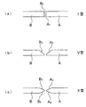
一般に、一対の石英ガラス部材を溶接する方法としては、石英ガラス製の溶接棒を使用し、この溶接棒を溶融することによって石英ガラス部材同士を接合する方法がとられており、この方法は比較的容易に石英ガラス製品を製造することができるという有利さがある。しかし、その反面、溶接棒を溶融した溶融体を溶接部位に充分に溶着させることが必要で、熟練した作業者の経験と技能を必要とし、作業時間が長くなるという不利があった。なお、石英ガラス部材を溶接する態様としては、溶接する際の溶接部位の端面の形状の変化によって、図5に示したような3種類の態様が知られている。即ち、石英ガラス部材A,Bの溶接部位の端面が平坦面A1,B1であるI型〔図5(a)〕、端面が先端方向に下向きの片面テーパ面A2,B2を有するV型〔図5(b)〕及び端面が先端方向に下向き及び上向きの両面テーパ面A3,A4,B3,B4を有するX型〔図5(c)〕である。 In general, as a method of welding a pair of quartz glass members, a method of joining quartz glass members by using a welding rod made of quartz glass and melting the welding rod is used. There is an advantage that a quartz glass product can be manufactured easily. However, on the other hand, it is necessary to sufficiently weld the melted material of the welding rod to the welding site, which requires the experience and skill of a skilled worker, and has the disadvantage that the working time becomes long. As a mode of welding the quartz glass member, there are known three types of modes as shown in FIG. 5 depending on a change in the shape of the end face of the welded portion when welding. In other words, the end surfaces of the welded portions of the quartz glass members A and B are the flat surfaces A 1 and B 1 (FIG. 5 (a)), and the end surfaces have single-side tapered surfaces A 2 and B 2 that face downward in the tip direction. V type (FIG. 5 (b)) and X type (FIG. 5 (c)) having double-sided tapered surfaces A 3 , A 4 , B 3 , B 4 whose end faces are downward and upward in the tip direction.
上述したような溶接棒を用いる溶接方法における不利を克服するために、溶接棒を用いることなく機械的に石英ガラス部材の接合を行う方法及び装置が提案されている(特許文献1)。この特許文献1に記載の従来方法について、図6及び図7を用いて説明する。図6はこの従来方法の工程順の1例を示すフローチャート及び図7はこの従来方法の手順の1例を示す正面模式図である。この従来方法においては、まず、石英ガラス部材A,Bの接合部A1,B1を突き合わせる〔図6のステップ200、図7の(a)〕。この従来方法における石英ガラス部材A,Bは左右方向(この場合、バーナは上下方向)又は上下方向(この場合、バーナは左右方向)に対置されるが、その接合部は常に水平方向に位置する構成(バーナも常に水平方向加熱のみ)を開示するのみで石英ガラス部材A,Bを左右方向に縦置きに対置して接合部が垂直方向に位置する構成(バーナも垂直方向加熱)についての開示又は示唆は全くない。
In order to overcome the disadvantages in the welding method using a welding rod as described above, a method and apparatus for mechanically joining quartz glass members without using a welding rod has been proposed (Patent Document 1). The conventional method described in Patent Document 1 will be described with reference to FIGS. FIG. 6 is a flowchart showing an example of the order of steps of this conventional method, and FIG. 7 is a schematic front view showing an example of the procedure of this conventional method. In this conventional method, first, the joining portions A 1 and B 1 of the quartz glass members A and B are brought into contact with each other (
次に、水平方向に配置されたバーナ部によって石英ガラス部材A,Bの接合部A1,B1の両側から該接合部全体を均一に加熱し溶融する〔図6のステップ202,図7の(b)〕。さらに、石英ガラス部材A,Bに外力を加え、該接合部A1,B1全体を押し合わせ溶着部Dを介して溶着させ〔図6のステップ204,図7の(c)〕、溶接石英ガラス部材YABを作成する〔図7の(d)〕。この従来方法においては、石英ガラス部材A,Bは静止的外力(速度を持たせない)で押し合わされ、そのために、I型の接合状態で接合が平滑に仕上げられる。後述する本発明方法においては、石英ガラス部材A,Bは所定の速度を持たせた外力で押し合わせるため、接合部分には盛り上がり凸部が形成される。この点が、この従来方法と本発明方法の相違点の1つである。この溶接石英ガラスYABに対して、必要に応じて、その溶着部D又はその近傍にアニール処理を施して熱歪み除去を行う(図6のステップ206)。その後、この溶接石英ガラスYABを冷却させ(図6のステップ208)、溶接石英ガラス部材YABを完成する。
Next, the entire joining portion is uniformly heated and melted from both sides of the joining portions A 1 and B 1 of the quartz glass members A and B by the burner portions arranged in the horizontal direction [
この特許文献1に記載の技術では石英ガラス部材(板形状)をワーク把握手段の上に、平面状に固定して、石英ガラス部材を突き合わせた状態にて加熱・溶融させる溶接形態をとっていた。しかし、この石英ガラス部材を平面状(横置き)に配置させた状態で、石英ガラス部材の両面を上下方向より加熱・溶融させると、溶融段階で、石英ガラス部材の自重により、下方に垂れ落ちる傾向があった。下方に垂れた状態で溶接を行うと、溶接面の上面側に、垂れが生じその分の凹部が出来てしまい、溶接した石英ガラス部材の平面性が確保されないことがある。このような凹部が生ずると、研削によってその凹部を解消する必要があるが、凹部研削は凸部研削に比較して困難な作業を伴うこととなり、大きな問題となる。 The quartz glass member (plate shape) with the technique described in Patent Document 1 above the workpiece gripping means, fixed to the flat, was taking weld form of heating and melting in a state of matching the quartz glass member . However, when both surfaces of the quartz glass member are heated and melted from above and below in a state where the quartz glass member is arranged in a flat shape (horizontally placed), it droops downward due to the weight of the quartz glass member at the melting stage. There was a trend. When welding is performed in a state where it is drooped downward, drooping occurs on the upper surface side of the welding surface, and a corresponding recess is formed, and the flatness of the welded quartz glass member may not be ensured. When such a concave portion is generated, it is necessary to eliminate the concave portion by grinding. However, the concave portion grinding involves a difficult work as compared with the convex portion grinding, which is a serious problem.
また、上記した特許文献1の方法では、I型の突き合わせ溶接を行うと、肉厚の石英ガラス部材(例えば、厚さ12mm)の溶接部内部に泡の混入が発生することが解った。泡の混入が生ずる要因は、(1)石英ガラス部材の肉厚が大きいこと、(2)石英ガラス部材端面の形状が平たい形状、つまり、I型であること、(3)石英ガラス端面の下地状態(肌仕上げの状態)つまり、表面粗さが粗い場合、(4)加熱によって左右される石英ガラスの溶融不足などがある。このように、溶接部分に泡が混入すると光学的ムラが存在することとなり、光学装置用、例えば紫外線洗浄装置用合成石英ガラス部材等として用いるには不適当であった。 Moreover, in the method of patent document 1 mentioned above, when I type butt welding was performed, it turned out that mixing of a bubble generate | occur | produces inside the welding part of a thick quartz glass member (for example, thickness 12mm). The factors causing the mixing of bubbles are (1) the thickness of the quartz glass member is large, (2) the shape of the end surface of the quartz glass member is flat, that is, the I type, and (3) the base of the end surface of the quartz glass. When the state (skin finish state), that is, when the surface roughness is rough, (4) there is insufficient melting of quartz glass that is influenced by heating. As described above, when bubbles are mixed in the welded portion, optical unevenness exists, which is inappropriate for use as a synthetic quartz glass member for an optical device, for example, an ultraviolet cleaning device.
そこで、本発明者らは、肉厚の石英ガラス部材の溶接面が盛り上がるくらいの溶接を目的として、石英ガラス部材を加熱、溶融及び溶着することで、上記の問題を乗り越えた溶接方法を開発すべく、鋭意研究を続けた結果、本発明に到達したものである。 Accordingly, the present inventors have developed a welding method that overcomes the above-mentioned problems by heating, melting, and welding the quartz glass member for the purpose of welding that raises the weld surface of the thick quartz glass member. Therefore, as a result of intensive research, the present invention has been achieved.
本発明は、石英ガラス部材の溶接部分に凹部の発生や泡の混入がなく、したがって光学的ムラが生ずることがなく、溶接棒を用いずに、簡便に石英ガラス部材を溶接することができ、光学装置用として好適に用いることができるようにした石英ガラス部材の溶接方法及び装置を提供することを目的とする。 In the present invention, there is no generation of recesses or bubbles in the welded portion of the quartz glass member, and therefore optical non-uniformity does not occur, and the quartz glass member can be easily welded without using a welding rod, An object of the present invention is to provide a method and apparatus for welding a quartz glass member that can be suitably used for an optical device.
上記課題を解決するために、本発明の石英ガラス部材の溶接方法は、相対向する一対の石英ガラス部材の端面同士を溶接する装置を用いる溶接方法であり、一方の石英ガラス部材を縦置き状態で支持する固定支持手段と、他方の石英ガラス部材を縦置き状態で支持するとともに前記固定支持手段に相対向して接離可能に設けられた可動支持手段と、前記一対の石英ガラス部材の相対向する端面である溶接部位を加熱溶融することができるように前記固定支持手段と可動支持手段との間に設けられたバーナ手段とからなる石英ガラス部材の溶接装置を用いるとともに、前記石英ガラス部材を所定の間隔をおいて縦置きに対置させる工程と、前記石英ガラス部材の端面である溶接部位を前記溶接部位の両側から前記バーナ手段によって均一に加熱溶融する工程と、前記一対の石英ガラス部材の溶融した端面である溶接部位を所定の押圧力によって突き合わせかつ押し合わせて溶着する工程と、からなり、前記溶着された石英ガラス部材の溶着部分に盛り上がり凸部が形成されるようにした石英ガラス部材の溶接方法であって、前記溶着された石英ガラス部材の溶着部分及びその近傍部分を前記バーナ手段によって加熱軟化させることによって熱歪みを分散させる工程をさらに有し、前記溶着された石英ガラス部材が冷却した後、前記盛り上がり凸部を研削して平坦とすることを特徴とする。本発明方法で用いる押圧力としては、両方向から外力を加えてもよいが、所定の速度を持たせた一方向からの外力を用いるのが好ましい。 In order to solve the above-mentioned problem, the method for welding quartz glass members of the present invention is a welding method using an apparatus for welding end faces of a pair of opposing quartz glass members, and one quartz glass member is placed in a vertical state. A stationary support means that supports the other quartz glass member in a vertically placed state, a movable support means that is provided so as to be able to contact and separate from the fixed support means, and a relative relationship between the pair of quartz glass members. A quartz glass member welding apparatus comprising a burner means provided between the fixed support means and the movable support means so as to heat and melt a welded portion which is an end surface facing the quartz glass member. uniformly heated by the burner unit and a step of opposing the vertically at predetermined intervals, the welded part is an end of the quartz glass member from both sides of the welded section A step of melt, a step of welding the molten is an end welded part of the pair of quartz glass member against and press fit by a predetermined pressing force, consists, raised the welded portion of the welded quartz glass member A method of welding a quartz glass member in which a convex portion is formed, the step of dispersing thermal distortion by heating and softening a welded portion of the fused quartz glass member and its vicinity by the burner means In addition, after the welded quartz glass member is cooled, the raised convex portion is ground and flattened. As the pressing force used in the method of the present invention, an external force may be applied from both directions, but it is preferable to use an external force from one direction having a predetermined speed.
本発明方法においては、前記溶着された石英ガラス部材の溶着部分に盛り上がり凸部を形成するように石英ガラス部材を突き合せかつ押し合わせるのがよい。 In the method of the present invention, it is preferable that the quartz glass member is abutted and pressed so as to form a raised convex portion in the welded portion of the fused quartz glass member.
本発明方法においては、前記溶着された石英ガラス部材の溶着部分及びその近傍部分を加熱軟化させることによって熱歪みを分散させる工程をさらに実施するのが好ましい。 In the method of the present invention, it is preferable to further carry out a step of dispersing thermal strain by heating and softening the welded portion of the fused quartz glass member and its vicinity.
本発明の石英ガラス部材の溶接装置は、相対向する一対の石英ガラス部材の端面同士を溶接するために用いられる装置でありかつ上記した本発明の石英ガラス部材の溶接方法を実施するための装置であって、一方の石英ガラス部材を縦置き状態で支持する固定支持手段と、他方の石英ガラス部材を縦置き状態で支持するとともに前記固定支持手段に相対向して接離可能に設けられた可動支持手段と、前記一対の石英ガラス部材の相対向する端面である溶接部位を加熱溶融することができるように前記固定支持手段と可動支持手段との間に設けられたバーナ手段とからなることを特徴とする。 The apparatus for welding quartz glass members of the present invention is an apparatus used for welding end faces of a pair of opposing quartz glass members , and an apparatus for carrying out the above-described method for welding quartz glass members of the present invention. A fixed support means for supporting one quartz glass member in a vertically placed state, and a quartz glass member for supporting the other quartz glass member in a vertically placed state, and provided so as to be able to contact and separate from the fixed support means. It consists of a movable support means and a burner means provided between the fixed support means and the movable support means so as to heat and melt the welded portions which are the opposite end surfaces of the pair of quartz glass members. It is characterized by.
前記バーナ手段としては1対のストレートバーナを用い、前記石英ガラス部材の溶接部位に対して平行でかつその両側に位置する状態で設けるのが好ましい。 It is preferable that a pair of straight burners is used as the burner means, and the burner means is provided in a state parallel to the welded portion of the quartz glass member and positioned on both sides thereof.
前記バーナ手段としては、上下方向に移動可能であり、かつ任意角度に傾斜可能であるように設置するのが好適である。 The burner means is preferably installed so that it can move in the vertical direction and can be inclined at an arbitrary angle.
本発明方法によれば、石英ガラス部材の溶接部分に凹部の発生や泡の混入がなく、したがって光学的ムラが生ずることがなく、溶接棒を用いずに、簡便に石英ガラス部材を溶接することができ、得られた溶接石英ガラス部材は光学装置用石英ガラス部材として好適に用いられるという効果が達成される。本発明装置は、本発明方法の実施に有効に用いられる。 According to the method of the present invention, there is no generation of recesses or bubbles in the welded portion of the quartz glass member, so that optical unevenness does not occur, and the quartz glass member can be simply welded without using a welding rod. Thus, the effect that the obtained fused quartz glass member is suitably used as a quartz glass member for an optical device is achieved. The apparatus of the present invention is effectively used for carrying out the method of the present invention.
以下に本発明の実施の形態を添付図面に基づいて説明するが、図示例は例示的に示されるもので、本発明の技術思想から逸脱しない限り種々の変形が可能なことはいうまでもない。 DESCRIPTION OF THE PREFERRED EMBODIMENTS Embodiments of the present invention will be described below with reference to the accompanying drawings. However, the illustrated examples are illustrative only, and various modifications can be made without departing from the technical idea of the present invention. .
図1は本発明に係る石英ガラス部材の溶接装置の斜視説明図である。図中、10は本発明に係わる石英ガラス部材の溶接装置である。この溶接装置10は、第1石英ガラス部材Aを支持する固定支持手段14を有している。16は固定支持手段14を構成する第1基台である。この第1基台16の上面には第1石英ガラス部材Aの下部を支持する第1下部支持具18a,18b及び第1補助受け具18c,18dが設けられている。20a,20bは第1石英ガラス部材Aの上部を支持する第1上部支持具である。
FIG. 1 is a perspective view of a quartz glass member welding apparatus according to the present invention. In the figure,
22は第2石英ガラス部材Bを支持する可動支持手段で、前記固定支持手段14に相対向して接離可能に設けられている。26は可動支持手段22を構成する第2基台である。この第2基台26の上面にはレール28,28が長手方向に敷設され、このレール28,28上には可動台30が長手方向に摺動自在に取り付けられている。この可動台30の上面には第2石英ガラス部材Bの下部を支持する第2下部支持具32a,32b及び第2補助受け具32c,32dが設けられている。34a,34bは第2石英ガラス部材Bの上部を支持する第2上部支持具である。上述した各支持具18a,18b,20a,20b,32a,32b,34a,34bについては機械的な静的精度が保たれており、予め寸法設定された石英ガラス部材A,Bを支持するとその溶接部位である端面A1,B1が同一線上で互いに向き合うように構成されている。
22 is a movable support means for supporting the second quartz glass member B, and is provided so as to be opposed to and separate from the fixed support means 14.
36は第3基台で、第1基台16及び第2基台26の間に設けられている。この第3基台36の上面には一対のストレートバーナ38a,38bからなるバーナ手段38を保持するバーナ保持部材40が設置されている。このバーナ手段38は石英ガラス部材A,Bの溶接部位A1,B1に対して平行でかつその両側に位置する状態で設けられている。このバーナ保持部材40は上下動自在かつ傾斜角度調整可能に設置されており、したがって、バーナ手段38が上下方向に移動可能であり、かつ任意角度に傾斜することができるようになっている。
上記した構成により、機械的精度の確保された固定支持手段14に支持された第1石英ガラス部材Aの溶接部位、即ち一方の端面A1と機械的精度の確保された可動支持手段22に支持された第2石英ガラス部材Bの溶接部位、即ち他方の端面B1とをバーナ手段38の火炎F,Fによって溶融し、この溶融した溶接部位A1,B1を可動支持手段22を固定支持手段14方向に移動させて溶接部位B1を溶接部位A1に所定の速度を持たせて突き合わせかつ押し合わせ(衝突させ)ることによって溶着させることができる。この時、溶接部位A1,B1を衝突させる外力(所定の速度を持たせた一方向からの外力)でもって突き合わせかつ押し合わせることで溶接部分には盛り上がり凸部Cが形成される(図3及び図4)。 With the configuration described above support, the welding portion of the first silica glass member A which is supported on the fixed support means 14 which is secured in the mechanical precision, i.e. the one end face A 1 and the mechanical precision movable support means 22 which is secured in the weld site of the second silica glass member B, that is the end surface B 1 of the other side were melted by the flame F, F of the burner means 38, the welded part a 1, B 1 was molten fixing the movable support means 22 support means 14 direction to have a predetermined speed welding site B 1 is moved to the welding site a 1 to butt and press adjustment (collide) can be welded by Rukoto. At this time, a raised protrusion C is formed in the welded part by abutting and pressing with an external force (external force from one direction having a predetermined speed) that causes the welded parts A 1 and B 1 to collide (see FIG. 3 and FIG. 4).
なお、必要に応じて、バーナ手段38を用いて、この溶接した石英ガラス部材の溶接部分を軟化加熱させることによって熱歪みの分散を行うことができる。ある任意の傾斜角度で位置させたストレートの加熱装置(石英ガラス部材に対しては1対のストレートバーナ)で、溶接部分及びその近傍部分(バーナの可動範囲部分)を、石英ガラスの軟化点近くまで加熱することで、溶接によって生じた熱歪みを分散させることができ、溶接石英ガラス部材の割れの発生がなくなる。また、通常は、溶接後にアニール炉でのアニール処理を行うが、アニール処理は石英ガラス部材全体を軟化点近くまで加熱して歪み取り(アニール)を行うために、面積の大きい板は、その平面性が失われるという不都合があった。しかし、このストレートの加熱装置を用いることによって、固定支持手段14及び可動支持手段22について設定された機械的精度と同様な平面性が確保された状態で溶接石英ガラス部材が得られるという有利さがある。 If necessary, the thermal strain can be dispersed by softening and heating the welded portion of the welded quartz glass member using the burner means 38. With a straight heating device (a pair of straight burners for quartz glass members) positioned at an arbitrary tilt angle, the welded part and its vicinity (the burner movable range part) are close to the softening point of quartz glass. By heating up to, it is possible to disperse the thermal strain caused by welding, and the generation of cracks in the welded quartz glass member is eliminated. In general, annealing is performed in an annealing furnace after welding. In the annealing process, the entire quartz glass member is heated to near the softening point to remove strain (annealing). There was an inconvenience of loss of sex. However, by using this straight heating device, there is an advantage that a welded quartz glass member can be obtained in a state in which flatness similar to the mechanical accuracy set for the fixed support means 14 and the movable support means 22 is secured. is there.
続いて、本発明に係る石英ガラス部材の溶接方法について図1に示した本発明の溶接装置を参照しつつ、図2〜図4を用いて説明する。図2は本発明に係る石英ガラス部材の溶接方法の工程順の1例を示すフローチャート、図3は本発明方法の手順の1例を示す正面模式図及び図4は図3と同様の手順を示す上面模式図である。 Next, a method for welding a quartz glass member according to the present invention will be described with reference to FIGS. 2 to 4 with reference to the welding apparatus of the present invention shown in FIG. FIG. 2 is a flowchart showing an example of the process sequence of the method for welding quartz glass members according to the present invention, FIG. 3 is a schematic front view showing an example of the procedure of the method of the present invention, and FIG. 4 shows the same procedure as FIG. It is an upper surface schematic diagram shown.
まず、一対の石英ガラス部材A,Bを所定の間隔をおいて縦置きに対置させる〔図2のステップ100、図3及び図4の(a)〕。つまり、固定支持手段14に一方の石英ガラス部材Aを縦置きに支持させ、可動支持手段22に他方の石英ガラス部材Bを縦置きに支持させる。可動支持部材22に支持された石英ガラス部材Bを移動させることによって石英ガラス部材A,Bを所定間隔をおいて縦置きに対置させることができる。
First, a pair of quartz glass members A and B are placed vertically with a predetermined interval [
次に、バーナ手段38を用いて石英ガラス部材A,Bの溶接部位A1,B1を均一に加熱溶融する〔図2のステップ102,図3及び図4の(b)(c)〕。可動支持部材22に支持された石英ガラス部材Bを移動させることによってこの溶融した溶接部位A1,B1を所定の速度を持たせて突き合わせ、かつ押し合わせて押圧状態とし、外周面に突出した盛り上がり凸部Cを形成した状態で溶着し、石英ガラス部材A,Bを溶接して溶接石英ガラス部材WABを作成する〔図2のステップ104,図3及び図4の(d)(e)〕。上記した突き合わせの態様としては、他方の石英ガラス部材のみを移動させる場合について説明したが、両方の石英ガラス部材を移動させてもよいものである。
Next, the welded portions A 1 and B 1 of the quartz glass members A and B are uniformly heated and melted using the burner means 38 [
この溶接石英ガラス部材WABに対して、必要に応じて、バーナ手段38を用いてその溶接部分及びその近傍部分を加熱軟化させることによって熱歪みを分散させる(図2のステップ106)。その後、この溶接石英ガラスWABを冷却する(図2のステップ108)。この冷却の方法としては特別の限定はないが、溶接石英ガラス部材WABを大気中に放置して自然冷却させればよい。この冷却した溶接石英ガラスWABの凸部Cを研削して平坦とし(図2のステップ110)、溶接石英ガラス部材WABを完成する(図2のステップ112)。このようにして得られた石英ガラス部材WABは、その溶接部分に泡の混入がなく、したがって、光学的ムラの発生がなく、光学装置用、例えば紫外線洗浄装置用石英ガラス部材等として良好な性能を有する。
For this welding quartz glass member W AB, optionally, dispersing the thermal distortion by heat softening the weld portion and its vicinity with the burner unit 38 (
なお、図3及び図4の例では、石英ガラス部材A,Bの溶接部位がI型〔図5(a)〕である場合について説明したが、その他の態様、即ちV型〔図5(b)〕、X型〔図5(c)〕のように溶接部位の端面を面取りした場合についても同様に適用可能であることはいうまでもない。特にX型の態様においては、例えば、12mm肉厚(先端端面4mm)の石英ガラス部材の場合でも、先端中央部にバーナ火炎が当たり、バーナ火炎による溶解も起こり易くなる。また同様に端面の面取り部分には45度面でバーナ火炎が当たることになり、I型に比べて、より溶解が増す。つまり、X型はI型に比べ、バーナ火炎のスポット分またはスポット幅の能率がよくなり、溶解に影響し、石英ガラス部材端面の溶解度が増えるために、石英ガラス部材同士の溶着仕上がりを制御・操作し易くなる利点がある。また、X型石英ガラス部材についての溶接作業を行う場合には、突き合わせ衝突させる速度を速くすれば、溶着部分の盛り上がり凸部の幅や高さがI型石英ガラス部材の溶着部分に比べて大きくすることができる。 In the example of FIGS. 3 and 4, the case where the welded portion of the quartz glass members A and B is the I type [FIG. 5A] is described, but other modes, that is, the V type [FIG. )], X type [FIG. 5 (c)] Needless to say, the present invention can be similarly applied to the case where the end face of the welded portion is chamfered. In particular, in the case of the X-type, for example, even in the case of a quartz glass member having a thickness of 12 mm (tip end surface 4 mm), a burner flame hits the center of the tip, and melting by the burner flame easily occurs. Similarly, the chamfered portion of the end face is exposed to a burner flame at a 45 degree face, and the dissolution is further increased as compared with the I type. In other words, compared to the I type, the X type has better efficiency of the spot or width of the burner flame, affects the melting, and increases the solubility of the end face of the quartz glass member. There is an advantage that it is easy to operate. Further, when performing the welding operation on the X-type quartz glass member, if the speed of the butt collision is increased, the width and height of the raised convex portion of the welded portion are larger than those of the welded portion of the I-type quartz glass member. can do.
10:溶接装置、14:固定支持手段、16:第1基台、18a,18b:第1下部支持具、20a,20b:第1上部支持具、22:可動支持手段、26:第2基台、28:レール、30:可動台、32a,32b:第2下部支持具、34a,34b:第2上部支持具、36:第3基台、38a,38b:ストレートバーナ、38:バーナ手段、40:バーナ保持部材、A,B:石英ガラス部材。
10: welding apparatus, 14: fixed support means, 16: first base, 18a, 18b: first lower support, 20a, 20b: first upper support, 22: movable support, 26: second base 28: Rail, 30: Movable stand, 32a, 32b: Second lower support, 34a, 34b: Second upper support, 36: Third base, 38a, 38b: Straight burner, 38: Burner means, 40 : Burner holding member, A, B: Quartz glass member.
Claims (5)
Priority Applications (4)
| Application Number | Priority Date | Filing Date | Title |
|---|---|---|---|
| JP2004104884A JP4486392B2 (en) | 2004-03-31 | 2004-03-31 | Method and apparatus for welding quartz glass member |
| KR1020067007754A KR101100845B1 (en) | 2004-03-31 | 2005-02-04 | Welding method and welder of quartz glass member |
| PCT/JP2005/001699 WO2005100272A1 (en) | 2004-03-31 | 2005-02-04 | Welding method and welder of quartz glass member |
| TW094105297A TW200535108A (en) | 2004-03-31 | 2005-02-22 | Method and apparatus for welding quartz glass member |
Applications Claiming Priority (1)
| Application Number | Priority Date | Filing Date | Title |
|---|---|---|---|
| JP2004104884A JP4486392B2 (en) | 2004-03-31 | 2004-03-31 | Method and apparatus for welding quartz glass member |
Publications (2)
| Publication Number | Publication Date |
|---|---|
| JP2005289696A JP2005289696A (en) | 2005-10-20 |
| JP4486392B2 true JP4486392B2 (en) | 2010-06-23 |
Family
ID=35149912
Family Applications (1)
| Application Number | Title | Priority Date | Filing Date |
|---|---|---|---|
| JP2004104884A Expired - Lifetime JP4486392B2 (en) | 2004-03-31 | 2004-03-31 | Method and apparatus for welding quartz glass member |
Country Status (4)
| Country | Link |
|---|---|
| JP (1) | JP4486392B2 (en) |
| KR (1) | KR101100845B1 (en) |
| TW (1) | TW200535108A (en) |
| WO (1) | WO2005100272A1 (en) |
Families Citing this family (12)
| Publication number | Priority date | Publication date | Assignee | Title |
|---|---|---|---|---|
| JP5248162B2 (en) * | 2008-03-31 | 2013-07-31 | コバレントマテリアル徳山株式会社 | Manufacturing method of quartz glass substrate |
| CN102659303A (en) * | 2012-03-30 | 2012-09-12 | 湖州奥博石英科技有限公司 | Quartz spliced product and manufacturing method thereof |
| KR101433668B1 (en) * | 2012-09-10 | 2014-08-26 | (주) 디에스테크노 | Welding method for the quartz glass plate |
| CN106396355B (en) * | 2016-08-31 | 2019-11-22 | 成都富通光通信技术有限公司 | A kind of glass bar welding process |
| US11739019B2 (en) | 2019-01-22 | 2023-08-29 | Heraeus Quartz North America Llc | High-strength welding process for making heavy glass preforms with large cross sectional areas |
| KR20200117770A (en) | 2019-04-05 | 2020-10-14 | (주) 디에스테크노 | Ceramic glass bonding method in which paste is used |
| CN110127993A (en) * | 2019-05-17 | 2019-08-16 | 湖州东科电子石英有限公司 | The welding procedure of opaque quartz plate and suprasil stick |
| KR20210016874A (en) | 2019-08-05 | 2021-02-17 | (주) 디에스테크노 | Welding method for the glass celamic plate |
| KR20210056707A (en) | 2019-11-11 | 2021-05-20 | (주) 디에스테크노 | The Bonding Method For The Glass Celamic Plate |
| CN112133658A (en) * | 2020-09-29 | 2020-12-25 | 吴静立 | Processing production method of quartz boat |
| KR102559225B1 (en) * | 2021-04-28 | 2023-07-25 | 대한광통신(주) | Glass bulk joining method for enlarging glass bulk |
| CN116395945B (en) * | 2023-04-14 | 2023-12-08 | 浙江泓芯半导体有限公司 | Control system for quartz fusion positioning |
Citations (2)
| Publication number | Priority date | Publication date | Assignee | Title |
|---|---|---|---|---|
| JPS6355128A (en) * | 1986-08-22 | 1988-03-09 | Nippon Electric Glass Co Ltd | Production of thin plate glass |
| JP2003026433A (en) * | 2001-05-10 | 2003-01-29 | Tokuyama Toshiba Ceramics Co Ltd | Method of joining quartz glass member and joining equipment used for this method |
Family Cites Families (1)
| Publication number | Priority date | Publication date | Assignee | Title |
|---|---|---|---|---|
| DE10053402B4 (en) * | 2000-10-24 | 2008-04-17 | Institut für Fügetechnik und Werkstoffprüfung GmbH | Process and device for thermal joining of components made of silicate materials, silicate composites and silicate composite materials |
-
2004
- 2004-03-31 JP JP2004104884A patent/JP4486392B2/en not_active Expired - Lifetime
-
2005
- 2005-02-04 KR KR1020067007754A patent/KR101100845B1/en active IP Right Grant
- 2005-02-04 WO PCT/JP2005/001699 patent/WO2005100272A1/en active Application Filing
- 2005-02-22 TW TW094105297A patent/TW200535108A/en unknown
Patent Citations (2)
| Publication number | Priority date | Publication date | Assignee | Title |
|---|---|---|---|---|
| JPS6355128A (en) * | 1986-08-22 | 1988-03-09 | Nippon Electric Glass Co Ltd | Production of thin plate glass |
| JP2003026433A (en) * | 2001-05-10 | 2003-01-29 | Tokuyama Toshiba Ceramics Co Ltd | Method of joining quartz glass member and joining equipment used for this method |
Also Published As
| Publication number | Publication date |
|---|---|
| KR101100845B1 (en) | 2012-01-02 |
| TWI349654B (en) | 2011-10-01 |
| TW200535108A (en) | 2005-11-01 |
| WO2005100272A1 (en) | 2005-10-27 |
| JP2005289696A (en) | 2005-10-20 |
| KR20070027490A (en) | 2007-03-09 |
Similar Documents
| Publication | Publication Date | Title |
|---|---|---|
| KR101100845B1 (en) | Welding method and welder of quartz glass member | |
| JP5731983B2 (en) | Method and apparatus for cutting brittle workpiece | |
| KR101140164B1 (en) | Method?of?forming?scribe?line?on?substrate?of?brittle?material?and?scribe?line?forming?apparatus | |
| JP5756574B2 (en) | Splitting glass ribbon with low energy | |
| US7772522B2 (en) | Method for scribing substrate of brittle material and scriber | |
| JP2003026433A (en) | Method of joining quartz glass member and joining equipment used for this method | |
| JP4408607B2 (en) | Scribing method and scribing apparatus | |
| NO330040B1 (en) | Apparatus for friction stir welding | |
| KR100551526B1 (en) | Device and method for scribing fragile material substrate | |
| KR102228693B1 (en) | Steel plate material supply for laser cutting | |
| KR100649894B1 (en) | Method and device for scribing fragile material substrate | |
| JP2011230940A (en) | Cutting method for brittle material substrate | |
| KR101200789B1 (en) | Method for dividing brittle material substrate | |
| JP4134033B2 (en) | Scribing apparatus and scribing method for brittle material substrate | |
| JPWO2003013816A1 (en) | Method and apparatus for scribing brittle material substrate | |
| KR101821523B1 (en) | Apparatus and method for fusing using heating and vibration | |
| JP4438517B2 (en) | Method and apparatus for welding quartz glass tube member | |
| KR101433668B1 (en) | Welding method for the quartz glass plate | |
| CN112723732A (en) | Non-contact cutting method for cambered surface glass | |
| JP2006137168A (en) | Method and apparatus for breaking and cutting fragile material | |
| JP2000290031A (en) | Method for cutting channel-like glass and cutting device therefor | |
| JP7002294B2 (en) | Laser processing machine | |
| JP4560200B2 (en) | Method of welding quartz glass members | |
| JP7448970B2 (en) | Board breaking device and board breaking method | |
| KR102356498B1 (en) | Butt welding device for thin plate |
Legal Events
| Date | Code | Title | Description |
|---|---|---|---|
| A621 | Written request for application examination |
Free format text: JAPANESE INTERMEDIATE CODE: A621 Effective date: 20061213 |
|
| A131 | Notification of reasons for refusal |
Free format text: JAPANESE INTERMEDIATE CODE: A131 Effective date: 20091015 |
|
| RD02 | Notification of acceptance of power of attorney |
Free format text: JAPANESE INTERMEDIATE CODE: A7422 Effective date: 20091015 |
|
| A521 | Request for written amendment filed |
Free format text: JAPANESE INTERMEDIATE CODE: A523 Effective date: 20091210 |
|
| A131 | Notification of reasons for refusal |
Free format text: JAPANESE INTERMEDIATE CODE: A131 Effective date: 20100113 |
|
| A521 | Request for written amendment filed |
Free format text: JAPANESE INTERMEDIATE CODE: A523 Effective date: 20100301 |
|
| TRDD | Decision of grant or rejection written | ||
| A01 | Written decision to grant a patent or to grant a registration (utility model) |
Free format text: JAPANESE INTERMEDIATE CODE: A01 Effective date: 20100323 |
|
| A01 | Written decision to grant a patent or to grant a registration (utility model) |
Free format text: JAPANESE INTERMEDIATE CODE: A01 |
|
| A61 | First payment of annual fees (during grant procedure) |
Free format text: JAPANESE INTERMEDIATE CODE: A61 Effective date: 20100326 |
|
| R150 | Certificate of patent or registration of utility model |
Ref document number: 4486392 Country of ref document: JP Free format text: JAPANESE INTERMEDIATE CODE: R150 Free format text: JAPANESE INTERMEDIATE CODE: R150 |
|
| FPAY | Renewal fee payment (event date is renewal date of database) |
Free format text: PAYMENT UNTIL: 20130402 Year of fee payment: 3 |
|
| FPAY | Renewal fee payment (event date is renewal date of database) |
Free format text: PAYMENT UNTIL: 20130402 Year of fee payment: 3 |
|
| FPAY | Renewal fee payment (event date is renewal date of database) |
Free format text: PAYMENT UNTIL: 20140402 Year of fee payment: 4 |
|
| R250 | Receipt of annual fees |
Free format text: JAPANESE INTERMEDIATE CODE: R250 |
|
| R250 | Receipt of annual fees |
Free format text: JAPANESE INTERMEDIATE CODE: R250 |
|
| R250 | Receipt of annual fees |
Free format text: JAPANESE INTERMEDIATE CODE: R250 |
|
| R250 | Receipt of annual fees |
Free format text: JAPANESE INTERMEDIATE CODE: R250 |
|
| R250 | Receipt of annual fees |
Free format text: JAPANESE INTERMEDIATE CODE: R250 |
|
| R250 | Receipt of annual fees |
Free format text: JAPANESE INTERMEDIATE CODE: R250 |
|
| R250 | Receipt of annual fees |
Free format text: JAPANESE INTERMEDIATE CODE: R250 |
|
| R250 | Receipt of annual fees |
Free format text: JAPANESE INTERMEDIATE CODE: R250 |
|
| R250 | Receipt of annual fees |
Free format text: JAPANESE INTERMEDIATE CODE: R250 |
|
| R250 | Receipt of annual fees |
Free format text: JAPANESE INTERMEDIATE CODE: R250 |
|
| S531 | Written request for registration of change of domicile |
Free format text: JAPANESE INTERMEDIATE CODE: R313531 |
|
| R350 | Written notification of registration of transfer |
Free format text: JAPANESE INTERMEDIATE CODE: R350 |
|
| R250 | Receipt of annual fees |
Free format text: JAPANESE INTERMEDIATE CODE: R250 |