JP4486227B2 - Oral opening device - Google Patents
Oral opening device Download PDFInfo
- Publication number
- JP4486227B2 JP4486227B2 JP2000211557A JP2000211557A JP4486227B2 JP 4486227 B2 JP4486227 B2 JP 4486227B2 JP 2000211557 A JP2000211557 A JP 2000211557A JP 2000211557 A JP2000211557 A JP 2000211557A JP 4486227 B2 JP4486227 B2 JP 4486227B2
- Authority
- JP
- Japan
- Prior art keywords
- mouth
- pair
- oral cavity
- opening device
- corners
- Prior art date
- Legal status (The legal status is an assumption and is not a legal conclusion. Google has not performed a legal analysis and makes no representation as to the accuracy of the status listed.)
- Expired - Lifetime
Links
- 210000000214 mouth Anatomy 0.000 claims description 130
- 239000000463 material Substances 0.000 claims description 7
- 238000010586 diagram Methods 0.000 description 4
- 238000003780 insertion Methods 0.000 description 4
- 230000037431 insertion Effects 0.000 description 4
- 230000002093 peripheral effect Effects 0.000 description 4
- 230000000694 effects Effects 0.000 description 2
- -1 polyethylene Polymers 0.000 description 2
- 238000011282 treatment Methods 0.000 description 2
- QTBSBXVTEAMEQO-UHFFFAOYSA-M Acetate Chemical compound CC([O-])=O QTBSBXVTEAMEQO-UHFFFAOYSA-M 0.000 description 1
- 239000005977 Ethylene Substances 0.000 description 1
- 244000043261 Hevea brasiliensis Species 0.000 description 1
- 239000004698 Polyethylene Substances 0.000 description 1
- 239000004743 Polypropylene Substances 0.000 description 1
- 239000000853 adhesive Substances 0.000 description 1
- 230000001070 adhesive effect Effects 0.000 description 1
- 238000000034 method Methods 0.000 description 1
- 238000012986 modification Methods 0.000 description 1
- 230000004048 modification Effects 0.000 description 1
- 229920003052 natural elastomer Polymers 0.000 description 1
- 229920001194 natural rubber Polymers 0.000 description 1
- 210000003800 pharynx Anatomy 0.000 description 1
- 239000004033 plastic Substances 0.000 description 1
- 229920003023 plastic Polymers 0.000 description 1
- 229920000515 polycarbonate Polymers 0.000 description 1
- 239000004417 polycarbonate Substances 0.000 description 1
- 229920000573 polyethylene Polymers 0.000 description 1
- 229920001155 polypropylene Polymers 0.000 description 1
- 210000002784 stomach Anatomy 0.000 description 1
- 229920003051 synthetic elastomer Polymers 0.000 description 1
- 229920003002 synthetic resin Polymers 0.000 description 1
- 239000000057 synthetic resin Substances 0.000 description 1
- 239000005061 synthetic rubber Substances 0.000 description 1
- 210000003437 trachea Anatomy 0.000 description 1
- 238000002627 tracheal intubation Methods 0.000 description 1
- 229920002554 vinyl polymer Polymers 0.000 description 1
Images


Classifications
-
- A—HUMAN NECESSITIES
- A61—MEDICAL OR VETERINARY SCIENCE; HYGIENE
- A61C—DENTISTRY; APPARATUS OR METHODS FOR ORAL OR DENTAL HYGIENE
- A61C5/00—Filling or capping teeth
- A61C5/90—Oral protectors for use during treatment, e.g. lip or mouth protectors
Description
【0001】
【発明の属する技術分野】
本発明は、例えば、口腔内や咽頭部の診査、診療、撮影時、或いは気管内への挿管や胃カメラの挿入時等において使用される口腔開拡装置に関する。
【0002】
【従来の技術】
この種の口腔開拡装置としては、例えば、実公昭56−33524号公報に開示されるものが知られている。
【0003】
この実公昭56−33524号公報に開示されるものは、左右一対の口角鉤を有し、この一対の口角鉤を略U字状のバネアームを介して連結するものである。
【0004】
この口角開拡装置を使用する場合には、左右の口角鉤を手に持ち、この左右の口角鉤をバネアームのバネ力に抗して内側に向かって押し込むことにより、左右の口角鉤間の幅寸法を縮小させてから、患者の口腔内に挿入させて口角の両側部に引っ掛ける。しかるのち、左右の口角鉤から手を離すと、バネアームの復帰力により左右の口角鉤が開く方向に移動して口角が左右に押し広げられ、口腔内の診査、診療、撮影等を可能ならしめる。
【0005】
ところで、上記した口角鉤は、前歯部の診査、診療、写真撮影等を行う場合には好都合であるが、口角鉤だけでは口腔内の奥部側までは押し広げることができず、臼歯部の診査、診療、写真撮影等を行う場合には問題があった。
【0006】
そこで、近時においては、左右の口角鉤の外側部に外方に向かって突出する翼部をそれぞれ形成し、これら翼部により口腔内の奥部側を押し広げて臼歯部までの視野を広げることができるようにしたものが開発されている。
【0007】
【発明が解決しようとする課題】
しかしながら、口角鉤に翼部を外方に向かって突出形成した場合には、臼歯部まで視野を広げることができる利点はあるが、翼部間の幅寸法が大きくなるため、口腔内への挿入時には翼部が邪魔になり非常に挿入しずらくなる。このため、患者に苦痛を与えるとともに、使用者にとっても使用性が悪いものとなっていた。
【0008】
本発明は上記事情に着目してなされたもので、口角鉤に外方に向かって突出する翼部を形成しても口腔内に容易に挿入できるようにした口腔開拡装置を提供することを目的とする。
【0009】
【課題を解決するための手段】
上記課題を解決するため、請求項1記載の発明は、口腔内に挿入され、口角を押し広げる一対の口角鉤と、これら一対の口角鉤にそれぞれ外方に向かって突出形成され、前記口腔内の奥部側を押し広げる翼部と、前記一対の口角鉤を連結する略U字状のバネアーム部とを具備し、前記一対の口角鉤は前記口腔内に挿入される際、前記バネアームのバネ力に抗して互いに接近する方向に押圧されることにより互いの端部を当接させ、この当接部を回転支点として前記翼部を互いに接近するように内側に向かって回転させる構造を有し、かつ、前記当接される端部間の滑りを規制する端部に形成される規制部を有することを特徴とする。
【0010】
前記の構成により口腔内への挿入に際し、一対の口角鉤の翼部の位置関係が安定して平行状態を維持し、これにより、翼部間の幅寸法を縮小化して口腔内への挿入を容易に行うことができるようにする。
【0011】
また、回転支点の構造を小とし、口腔内への装着時においては回転支点が邪魔になることがないようにする。
【0012】
【発明の実施の形態】
以下、本発明を図面に示す実施の形態を参照して詳細に説明する。
【0013】
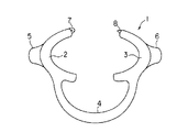
図1は本発明の第1の実施の形態である口腔開拡装置1を示す正面図で、図2はその上面図である。
【0014】
口腔開拡装置1は正面から見て円弧状をなす左右一対の口角鉤2,3と、これら一対の口角鉤2,3の下部側を連結する略U字状のバネアーム部4とから構成されている。
【0015】
左右一対の口角鉤2,3は所定間隔を存して離間対向して設けられ、その外周側部には凹溝2a,3aがそれぞれ形成されている。また、左右一対の口角鉤2,3の背面側には外方に向かって水平に延びる翼部5,6が一体に形成されている。
【0016】
左右一対の口角鉤2,3の凹溝2a,3aは口角の両側部を嵌め込ませるもので、翼部5,6は口腔の奥部側を押し広げるためのものである。
【0017】
左右一対の口角鉤2,3及び略U字状のバネアーム部4は弾力性に富むプラスチック、ポリカーボネート、ポリエチレン、ポリプロピレン等の合成樹脂材により一体に成形されている。
【0018】
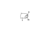
ところで、左側の口角鉤2の上部側の端部には図3にも示すように凹部7が形成され、右側の口角鉤3の上部側の端部には図4にも示すように突起部8が一体に突出成形されている。
【0019】
左右の口角鉤2,3が後述するように内側に向かって押し込まれて互いに接近する方向に移動したとき、左側の口角鉤2の凹部7内に右側の口角鉤3の突起部8が係合されるようになっている。
【0020】
次に、口腔開拡装置1の使用方法について図5乃至図8を参照して説明する。
【0021】
まず、図5に示すように、左右の口角鉤2,3の外周部を手の指9で挟持し、左右の口角鉤2,3をバネアーム部4のバネ力に抗して内側に押し込む。これにより、左右の口角鉤2,3が所定量押し込まれると、図6に示すように左側の口角鉤2の凹部7内に右側の口角鉤3の突起部8が挿入されて係合される。
【0022】
この状態からさらに、左右の口角鉤2,3を内側に向かって押し込むと、左右の口角鉤2,3は凹部7と突起部8との係合部を回転支点Kとして図7に示すように内側に向かって回転する。これにより、左右の口角鉤2,3の翼部5,6が互いに接近するように内側に向かって回転して略平行な状態となり、翼部5,6間の幅寸法Sが縮小化される。
【0023】
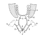
このように、翼部5,6の幅寸法Sを縮小化したのち、翼部5,6を患者の口角10から口腔11内に挿入させ、左右の口角鉤2,3の外周部の凹溝2a,3a内に口角10の両側部を嵌め込ませる。しかるのち、左右の口角鉤2,3の外側から指9を離す。これにより、図8に示すように、バネアーム部4が広がる方向に復帰し、左右の口角鉤2,3が互いに離間する方向に移動する。この移動により、患者の口角10が左右に押し広げられるとともに、翼部5,6により口腔11内の奥部側も同時に押し広げられる。
【0024】
このように口角10及び口腔11の奥部側を押し広げたのち、口腔11内の前歯部及び臼歯部の診査、診療、写真撮影等を行う。
【0025】
上記したように、左右の口角鉤2,3に凹部7及び突起部8を形成し、左右の口角鉤2,3を内側に押し込んでその凹部7と突起部8を係合させたのち、この係合部を回転支点Kとして安定して左右の口角鉤2,3の翼部5,6を互いに近接するように内側に向かって回転させるため、翼部5,6の位置関係を安定して水平状態を維持でき、翼部5,6間の幅寸法Sを大幅に縮小できる。
【0026】
従って、左右の口角鉤の翼部5,6を容易に患者の口腔11内に挿入することができ、患者に与える苦痛を大幅に軽減できるとともに、使用性も向上できるという利点がある。
【0027】
また、回転支点Kの構造が小さいため、口腔11内への装着時において回転支点Kが邪魔になることもない。
【0028】
図9は本発明の第2の実施の形態である口腔開拡装置21を示す正面図で、図10はその上面図である。
【0029】
なお、上記第1の実施の形態で示した部分と同一部分については、同一番号を付してその説明を省略する。
【0030】
この第2の実施の形態では、左右の口角鉤2,3の端部にそれぞれ突起部22,23を突出成形し、これら突起部22,23の表面にざらざらした粗面部22a,23aをそれぞれ形成している。
【0031】
左右の口角鉤2,3を口腔11内に挿入する際には、図11に示すように、左右の口角鉤2,3の外周部を手の指9で挟持し、左右の口角鉤2,3をバネアーム部4のバネ力に抗して内側に押し込む。これにより、左右の口角鉤2,3が所定量押し込まれると、左右の口角鉤2、3の端部の突起部22,23がその粗面部22a,23aを互いに当接させる。この状態からさらに、左右の口角鉤2,3を内側に向かって押し込むと、左右の口角鉤2,3は互いに当接する突起部22,23を回転支点Kとして図12に示すように内側に向かって回転する。これにより、左右の口角鉤2,3の翼部5,6が互いに接近するように内側に向かって回転して略平行な状態となり、翼部5,6間の幅寸法Sが縮小化される。
【0032】
この第2の実施の形態においても、上記した第1実施の形態と同様に、左右の口角鉤2,3の翼部5,6を患者の口腔11内に容易に挿入することができ、患者に与える苦痛を大幅に軽減できるとともに、使用性も向上できるという利点がある。
【0033】
この第2の実施の形態においては、左右の口角鉤2、3の端部の突起部22,23にそれぞれ粗面部22a,23aを形成したが、これに限られることなく、左右の口角鉤2、3の何れか一方の端部のみに粗面部を形成するようにしても良い。
【0034】
図13及び図14は本発明の第3の実施の形態を示すものである。
【0035】
この第3の実施の形態では、左右の口角鉤2,3の端部に歯車状に連続する溝部25,26を形成し、これら溝部25,26を当接させてかみ合せ、このかみ合せ部を左右の口角鉤2,3の翼部5,6の回転時における回転支点Kとしている。
【0036】
なお、左右の口角鉤2,3の端部に形成される溝部は歯車状に連続することなく、一個のみであっても良く、また、その形状も直線状、或いは、くの字状、又は、ジグザグ状であっても良い。
【0037】
また、本発明は、上記した第1乃至第3の実施の形態に限られることなく、左右の口角鉤2,3の端部を摩擦抵抗の大きな材質、例えば、天然ゴム、合成ゴム、エチレンビニルアセテート等の粘着性の高い材質で形成し、これら端部を当接させてこの当接部を左右の口角鉤2,3の翼部5,6の回転時における回転支点Kとするようにしても良い。
【0038】
なお、左右の口角鉤2,3の端部をそれぞれ摩擦抵抗の大きな材質で形成することなく、何れか一方の端部のみを摩擦抵抗の大きな材質で形成するようにしても良い。
【0039】
さらに、本発明はその主旨の範囲内であれば、上記した実施の形態に限られることなく、種々変形実施可能なことは勿論のことである。
【0040】
【発明の効果】
本発明は以上説明したように、一対の口角鉤を口腔内に挿入する際には、一対の口角鉤をバネアーム部のバネ力に抗して互いに接近する方向に押圧することにより互いの端部を当接させ、この当接部を回転支点として安定して翼部を互いに接近するように内側に向かって回転させる構造とするから、一対の口角鉤の翼部の位置関係を安定して平行状態を維持でき、翼部間の幅寸法を大幅に縮小化できる。
【0041】
従って、患者の口腔内への挿入が容易になり、患者に苦痛を与えることがないとともに、使用性も向上できるという効果を奏する。
【0042】
また、回転支点の構造が小さいため、口腔内への装着時において回転支点が邪魔になることもない。
【図面の簡単な説明】
【図1】本発明の第1の実施の形態である口腔開拡装置を示す正面図。
【図2】口腔開拡装置を示す上面図。
【図3】左側の口角鉤の端部に形成された凹部を示す斜視図。
【図4】右側の口角鉤の端部に突出形成された突起部を示す斜視図。
【図5】口腔内への挿入に際し、左右の口角鉤を指で挟持した状態を示す図。
【図6】左右の口角鉤を内側に向かって押し込んでその凹部と突起部を係合させた状態を示す図。
【図7】凹部と突起部の係合部を回転支点として左右の口角鉤の翼部を互いに近接するように内側に向かって回転させた状態を示す図。
【図8】口腔内に挿入された左右の口角鉤により口腔内が押し広げられた状態を示す図。
【図9】本発明の第2の実施の形態である口腔開拡装置を示す正面図。
【図10】口腔開拡装置を示す上面図。
【図11】口腔内への挿入に際し、左右の口角鉤を内側に向かって押し込んでその端部を互いに当接させた状態を示す図。
【図12】左右の口角鉤の互いに当接された端部を回転支点として左右の口角鉤の翼部を互いに近接するように内側に向かって回転させた状態を示す図。
【図13】本発明の第3の実施の形態である左側の口角鉤の端部に形成される歯車状の溝部を示す斜視図。
【図14】右側の口角鉤の端部に形成された歯車状の溝部を示す斜視図。
【符号の説明】
1…口腔開拡装置
2,3…口角鉤
2a,3a…口角を支える凹溝
4…バネアーム部
5,6…翼部
7…凹部
8…突起部
9…指
10…口角
11…口腔内
21…口腔開拡装置
22…突起部
22a…粗面部
23…突起部
23a…粗面部
25…溝部
26…溝部
S…翼部間の幅寸法
K…回転支点[0001]
BACKGROUND OF THE INVENTION
The present invention relates to a mouth opening device for use in, for example, examination of the oral cavity or pharynx, medical examination, photographing, intubation into the trachea or insertion of a stomach camera.
[0002]
[Prior art]
As this type of mouth opening device, for example, one disclosed in Japanese Utility Model Publication No. 56-33524 is known.
[0003]
What is disclosed in Japanese Utility Model Publication No. 56-33524 has a pair of left and right mouth corner ridges, and connects the pair of mouth corner ridges via a substantially U-shaped spring arm.
[0004]
When using this widening device, hold the left and right mouth corners in your hand and push the left and right mouth corners inward against the spring force of the spring arm. After reducing the dimensions, it is inserted into the patient's mouth and hooked to both sides of the mouth corner. After that, when you release your hands from the left and right mouth corner folds, the spring arm's return force moves the left and right mouth corner folds so that the mouth corners are pushed to the left and right, making it possible to conduct oral examinations, medical examinations, and photography. .
[0005]
By the way, the above-mentioned mouth folds are convenient when performing an examination, medical treatment, photography, etc. of the anterior teeth part, but the mouth folds alone cannot be pushed to the back side in the oral cavity, There were problems when conducting examinations, medical treatments, and taking pictures.
[0006]
Therefore, recently, wings projecting outward are formed on the outer sides of the left and right mouth folds, respectively, and these wings spread the back side of the oral cavity to widen the field of view to the molar part. Something that can be done has been developed.
[0007]
[Problems to be solved by the invention]
However, when the wings are formed to project outwardly on the corner folds, there is an advantage that the field of view can be expanded to the molar part, but the width dimension between the wings becomes large, so insertion into the oral cavity Sometimes the wings get in the way and are very difficult to insert. For this reason, it is painful for the patient, and the usability for the user is poor.
[0008]
The present invention has been made paying attention to the above circumstances, and it is intended to provide an oral spreading device that can be easily inserted into the oral cavity even if a wing portion that protrudes outward is formed on the mouth corner fold. Objective.
[0009]
[Means for Solving the Problems]
In order to solve the above-mentioned problem, the invention according to claim 1 is formed by a pair of mouth ridges that are inserted into the oral cavity and widen the mouth corners, and projecting outwardly from the pair of mouth corner folds, respectively. And a substantially U-shaped spring arm for connecting the pair of mouth corners, and when the pair of mouth corners are inserted into the oral cavity, the spring of the spring arm It has a structure in which the ends are brought into contact with each other by being pressed against each other against the force, and the wings are rotated inward so as to approach each other with the contact as a rotation fulcrum. And a restricting portion formed at an end portion for restricting slippage between the abutting end portions.
[0010]
When inserted into the oral cavity with the above configuration, the positional relationship between the wings of the pair of horns is stably maintained in a parallel state, thereby reducing the width dimension between the wings and inserting into the oral cavity. Make it easy to do.
[0011]
In addition, the structure of the rotation fulcrum is made small so that the rotation fulcrum does not get in the way when worn in the oral cavity.
[0012]
DETAILED DESCRIPTION OF THE INVENTION
Hereinafter, the present invention will be described in detail with reference to embodiments shown in the drawings.
[0013]
FIG. 1 is a front view showing a mouth opening device 1 according to a first embodiment of the present invention, and FIG. 2 is a top view thereof.
[0014]
The mouth opening device 1 is composed of a pair of left and right
[0015]
The pair of left and
[0016]
The
[0017]
The pair of left and
[0018]
By the way, a
[0019]
When the left and
[0020]
Next, the usage method of the oral cavity spreading apparatus 1 is demonstrated with reference to FIG. 5 thru | or FIG.
[0021]
First, as shown in FIG. 5, the outer peripheral portions of the left and
[0022]
When the left and
[0023]
Thus, after reducing the width dimension S of the
[0024]
In this way, after the mouth corner 10 and the back side of the
[0025]
As described above, the
[0026]
Therefore, the
[0027]
In addition, since the structure of the rotation fulcrum K is small, the rotation fulcrum K does not get in the way when mounted in the
[0028]
FIG. 9 is a front view showing a
[0029]
In addition, the same number is attached | subjected about the part same as the part shown in the said 1st Embodiment, and the description is abbreviate | omitted.
[0030]
In the second embodiment, the
[0031]
When the left and
[0032]
Also in the second embodiment, as in the first embodiment described above, the
[0033]
In the second embodiment, the
[0034]
13 and 14 show a third embodiment of the present invention.
[0035]
In the third embodiment,
[0036]
In addition, the groove part formed in the edge part of the left and
[0037]
The present invention is not limited to the first to third embodiments described above, and the ends of the left and
[0038]
In addition, you may make it form only either one edge part with a material with a big friction resistance, without forming the edge part of right-and-left
[0039]
Further, the present invention is not limited to the above-described embodiment, and various modifications can be made without departing from the spirit of the present invention.
[0040]
【The invention's effect】
As described above, in the present invention, when a pair of mouth corner folds is inserted into the oral cavity, the pair of mouth corner ridges are pressed against each other against the spring force of the spring arm portion so as to approach each other. , And the abutment part is used as a rotation fulcrum, and the wing parts are rotated inward so as to approach each other stably. The state can be maintained, and the width dimension between the wings can be greatly reduced.
[0041]
Therefore, insertion into the patient's oral cavity becomes easy, and there is an effect that the patient is not painful and usability can be improved.
[0042]
In addition, since the structure of the rotation fulcrum is small, the rotation fulcrum does not get in the way when mounted in the oral cavity.
[Brief description of the drawings]
FIG. 1 is a front view showing a mouth opening device according to a first embodiment of the present invention.
FIG. 2 is a top view showing the mouth opening device.
FIG. 3 is a perspective view showing a recess formed at an end of a left mouth corner fold.
FIG. 4 is a perspective view showing a protrusion that is formed to protrude from the end of the right mouth corner ridge.
FIG. 5 is a view showing a state in which the left and right mouth corner folds are held between fingers during insertion into the oral cavity.
FIG. 6 is a diagram showing a state in which the left and right mouth corner ridges are pushed inward to engage the recesses and the protrusions.
FIG. 7 is a view showing a state in which the wing portions of the left and right mouth ridges are rotated inward so as to be close to each other with the engaging portion of the concave portion and the protruding portion as a rotation fulcrum.
FIG. 8 is a diagram showing a state in which the oral cavity is pushed and widened by left and right mouth angular folds inserted into the oral cavity.
FIG. 9 is a front view showing an oral cavity spreading device according to a second embodiment of the present invention.
FIG. 10 is a top view showing the mouth opening device.
FIG. 11 is a diagram showing a state in which the left and right mouth ridges are pushed inward and the end portions thereof are brought into contact with each other when inserted into the oral cavity.
FIG. 12 is a diagram showing a state in which the left and right mouth corner wings are rotated inward so that the wing portions of the left and right mouth corners are close to each other with the end portions of the left and right mouth corners being in contact with each other as rotation fulcrums;
FIG. 13 is a perspective view showing a gear-shaped groove formed at an end portion of a left mouth corner ridge according to a third embodiment of the present invention.
FIG. 14 is a perspective view showing a gear-shaped groove formed at the end of the right mouth corner ridge.
[Explanation of symbols]
DESCRIPTION OF SYMBOLS 1 ... Oral spreading
Claims (5)
これら一対の口角鉤にそれぞれ外方に向かって突出形成され、前記口腔内の奥部側を押し広げる翼部と、
前記一対の口角鉤を連結する略U字状のバネアーム部と、
を具備し、
前記一対の口角鉤は前記口腔内に挿入される際、前記バネアームのバネ力に抗して互いに接近する方向に押圧されることにより互いの端部を当接させ、この当接部を回転支点として前記翼部を互いに接近するように内側に向かって回転させる構造を有し、かつ、前記当接される端部間の滑りを規制する端部に形成される規制部を有することを特徴とする口腔開拡装置。A pair of mouth horns that are inserted into the mouth and spread the mouth corners;
Each of these pair of mouth ridges is formed to protrude outward, and the wings that spread the back side of the oral cavity,
A substantially U-shaped spring arm portion connecting the pair of mouthpieces;
Comprising
When the pair of mouth ridges are inserted into the oral cavity, they are pressed against each other against the spring force of the spring arm so as to abut against each other, and this abutment is used as a rotation fulcrum. And having a structure for rotating the wings inward so as to approach each other, and having a restricting portion formed at an end for restricting slippage between the abutted ends. Oral spreading device.
Priority Applications (2)
| Application Number | Priority Date | Filing Date | Title |
|---|---|---|---|
| JP2000211557A JP4486227B2 (en) | 2000-07-12 | 2000-07-12 | Oral opening device |
| US09/900,197 US6500002B2 (en) | 2000-07-12 | 2001-07-09 | Oral cavity spreading apparatus |
Applications Claiming Priority (1)
| Application Number | Priority Date | Filing Date | Title |
|---|---|---|---|
| JP2000211557A JP4486227B2 (en) | 2000-07-12 | 2000-07-12 | Oral opening device |
Publications (2)
| Publication Number | Publication Date |
|---|---|
| JP2002017670A JP2002017670A (en) | 2002-01-22 |
| JP4486227B2 true JP4486227B2 (en) | 2010-06-23 |
Family
ID=18707644
Family Applications (1)
| Application Number | Title | Priority Date | Filing Date |
|---|---|---|---|
| JP2000211557A Expired - Lifetime JP4486227B2 (en) | 2000-07-12 | 2000-07-12 | Oral opening device |
Country Status (2)
| Country | Link |
|---|---|
| US (1) | US6500002B2 (en) |
| JP (1) | JP4486227B2 (en) |
Families Citing this family (30)
| Publication number | Priority date | Publication date | Assignee | Title |
|---|---|---|---|---|
| US7077805B1 (en) * | 2002-03-29 | 2006-07-18 | Si-1, Inc. | Ligament retractor assembly for use in performing knee surgery |
| AU2003210633A1 (en) * | 2002-07-02 | 2004-01-23 | The Children's Hospital Of Philadelphia | Mandibular occlusal inhibitor |
| US7160111B2 (en) * | 2002-09-24 | 2007-01-09 | Twilight Teeth, Inc. | Mouthpiece devices and methods to allow UV whitening of teeth |
| US8172570B2 (en) * | 2002-09-24 | 2012-05-08 | Twilight Teeth, Inc. | Mouthpiece devices and methods to allow UV whitening of teeth |
| EP1459698B1 (en) * | 2003-03-17 | 2005-12-21 | KerrHawe SA | Cheek and lip retractor for dentistry |
| WO2004108029A1 (en) * | 2003-06-11 | 2004-12-16 | Yun-Keun Kim | English pronunciation correcting device |
| US20060234187A1 (en) * | 2004-03-17 | 2006-10-19 | Kerrhawe Sa | Cheek and Lip Retractor For Dentistry |
| US20080064001A1 (en) * | 2004-07-02 | 2008-03-13 | Discus Dental, Llc | Retracting Devices |
| US20060069316A1 (en) * | 2004-07-02 | 2006-03-30 | Discus Dental Impressions, Inc. | Retracting devices |
| US20060063979A1 (en) * | 2004-08-25 | 2006-03-23 | Kenneth Rosenblood | Retracting devices |
| JP2006174917A (en) * | 2004-12-21 | 2006-07-06 | Takashi Chin | Angle wider |
| JP4696238B2 (en) * | 2005-09-06 | 2011-06-08 | 国立大学法人鳥取大学 | Artificial respiration aid for edentulous patients |
| US20070231773A1 (en) * | 2006-03-31 | 2007-10-04 | Curtis Pontynen | Methods, Devices, Systems and Kits for Isolating Teeth |
| AU2008304187B2 (en) * | 2007-09-26 | 2013-09-12 | Ultradent Products, Inc. | Methods, devices, systems, assemblies, and kits for tissue retraction in an oral cavity |
| JP4891191B2 (en) * | 2007-10-18 | 2012-03-07 | ティ.ケィ.ワィ株式会社 | Dentures for death makeup and methods for producing the same |
| US9339175B2 (en) * | 2007-12-31 | 2016-05-17 | International Business Machines Corporation | System and method to improve mouth disease diagnosis |
| US8753269B2 (en) * | 2009-04-23 | 2014-06-17 | Medtronic, Inc. | Minimally invasive access device for heart valve procedures |
| US8376743B1 (en) * | 2011-10-18 | 2013-02-19 | King Saud University | Oral retractor |
| US9427621B2 (en) * | 2012-11-07 | 2016-08-30 | Ronald L. Dristle | Face and lips exercise apparatus and methods of using the same |
| CN105142495B (en) | 2013-03-15 | 2018-07-17 | 厄耳他拉登脱产品股份有限公司 | Cheek pull device and method |
| USD756515S1 (en) * | 2014-03-10 | 2016-05-17 | Novartis Ag | Pupil expander |
| USD756516S1 (en) * | 2014-03-10 | 2016-05-17 | Novartis Ag | Pupil expander |
| USD763444S1 (en) | 2014-03-14 | 2016-08-09 | Ultradent Products, Inc. | Cheek retractor device |
| USD737964S1 (en) | 2014-03-14 | 2015-09-01 | Ultradent Products, Inc. | Cheek retractor device |
| USD792590S1 (en) | 2015-07-21 | 2017-07-18 | Ultradent Products, Inc. | Cheek retractor device |
| CN108309215A (en) * | 2018-02-01 | 2018-07-24 | 重庆医科大学附属第二医院 | A kind of metal correction opener |
| USD924398S1 (en) * | 2019-04-30 | 2021-07-06 | Dental Monitoring | Dentists apparatus for keeping the mouth open |
| USD914214S1 (en) | 2019-06-03 | 2021-03-23 | Ultradent Products, Inc. | Dental retraction device |
| CN112972044A (en) * | 2021-02-25 | 2021-06-18 | 成都缔优医疗科技有限公司 | Multifunctional mouth supporting device for department of stomatology |
| JP7022862B1 (en) * | 2021-06-25 | 2022-02-18 | 浩太郎 久保 | Angular cheilitis |
Citations (1)
| Publication number | Priority date | Publication date | Assignee | Title |
|---|---|---|---|---|
| JPH01155418U (en) * | 1988-04-19 | 1989-10-25 |
Family Cites Families (4)
| Publication number | Priority date | Publication date | Assignee | Title |
|---|---|---|---|---|
| JPS5633524A (en) | 1979-08-28 | 1981-04-04 | Nippon Soken Inc | Knocking detector for internal combustion engine |
| JPH0742406Y2 (en) * | 1991-12-10 | 1995-10-04 | 井上アタッチメント株式会社 | Mouth opener |
| US5199872A (en) * | 1991-12-10 | 1993-04-06 | Leal Francisco G B | Dental appliance |
| US5347996A (en) * | 1992-12-17 | 1994-09-20 | Huan Lee C | Mouth opener |
-
2000
- 2000-07-12 JP JP2000211557A patent/JP4486227B2/en not_active Expired - Lifetime
-
2001
- 2001-07-09 US US09/900,197 patent/US6500002B2/en not_active Expired - Fee Related
Patent Citations (1)
| Publication number | Priority date | Publication date | Assignee | Title |
|---|---|---|---|---|
| JPH01155418U (en) * | 1988-04-19 | 1989-10-25 |
Also Published As
| Publication number | Publication date |
|---|---|
| JP2002017670A (en) | 2002-01-22 |
| US20020022211A1 (en) | 2002-02-21 |
| US6500002B2 (en) | 2002-12-31 |
Similar Documents
| Publication | Publication Date | Title |
|---|---|---|
| JP4486227B2 (en) | Oral opening device | |
| US4909791A (en) | Safety cover for syringe needles | |
| JP5468255B2 (en) | Safety injection needle device with snap and manufacturing method thereof | |
| JP4350952B2 (en) | Needle shield assembly with hinged needle shield | |
| US4902227A (en) | Dental treatment tray | |
| JP4881734B2 (en) | Safety needle assembly and method of forming the safety needle assembly | |
| US5228466A (en) | Toothbrush | |
| US5483982A (en) | Dental floss device | |
| JP2003515360A5 (en) | ||
| US20160296308A1 (en) | Dental strip holder | |
| JP2007209635A (en) | Implement for opening labia oris | |
| JP3185409U (en) | Fixing clip for medical connection tube | |
| US20220160384A1 (en) | Device and method for treating nosebleeds | |
| US20060169299A1 (en) | Handle system for disposable flossers | |
| JP4819955B2 (en) | Lip opening device | |
| CN115666705A (en) | Medicine application tool, medicine application kit, and pressing tool for medicine application tool | |
| GB2144172A (en) | Nappy clip | |
| JPS6143413Y2 (en) | ||
| US1238001A (en) | Attachment for retractors. | |
| JPH0742406Y2 (en) | Mouth opener | |
| JP2023109703A (en) | Oral cavity wipe-cleaning sheet holding tool | |
| WO2023003885A1 (en) | Pacifier attachment clip and plush toy with pacifier attachment clip | |
| JPS6314721Y2 (en) | ||
| JP4680349B2 (en) | Needle cover and needle cover with cap and needle with wing with needle cover | |
| JPH0530430Y2 (en) |
Legal Events
| Date | Code | Title | Description |
|---|---|---|---|
| A621 | Written request for application examination |
Free format text: JAPANESE INTERMEDIATE CODE: A621 Effective date: 20070711 |
|
| A711 | Notification of change in applicant |
Free format text: JAPANESE INTERMEDIATE CODE: A712 Effective date: 20090507 |
|
| A521 | Request for written amendment filed |
Free format text: JAPANESE INTERMEDIATE CODE: A821 Effective date: 20090507 |
|
| A131 | Notification of reasons for refusal |
Free format text: JAPANESE INTERMEDIATE CODE: A131 Effective date: 20091117 |
|
| A521 | Request for written amendment filed |
Free format text: JAPANESE INTERMEDIATE CODE: A523 Effective date: 20100104 |
|
| A131 | Notification of reasons for refusal |
Free format text: JAPANESE INTERMEDIATE CODE: A131 Effective date: 20100202 |
|
| A521 | Request for written amendment filed |
Free format text: JAPANESE INTERMEDIATE CODE: A523 Effective date: 20100217 |
|
| TRDD | Decision of grant or rejection written | ||
| A01 | Written decision to grant a patent or to grant a registration (utility model) |
Free format text: JAPANESE INTERMEDIATE CODE: A01 Effective date: 20100316 |
|
| A01 | Written decision to grant a patent or to grant a registration (utility model) |
Free format text: JAPANESE INTERMEDIATE CODE: A01 |
|
| A61 | First payment of annual fees (during grant procedure) |
Free format text: JAPANESE INTERMEDIATE CODE: A61 Effective date: 20100326 |
|
| R150 | Certificate of patent or registration of utility model |
Free format text: JAPANESE INTERMEDIATE CODE: R150 |
|
| FPAY | Renewal fee payment (event date is renewal date of database) |
Free format text: PAYMENT UNTIL: 20130402 Year of fee payment: 3 |
|
| FPAY | Renewal fee payment (event date is renewal date of database) |
Free format text: PAYMENT UNTIL: 20140402 Year of fee payment: 4 |
|
| R250 | Receipt of annual fees |
Free format text: JAPANESE INTERMEDIATE CODE: R250 |
|
| R250 | Receipt of annual fees |
Free format text: JAPANESE INTERMEDIATE CODE: R250 |
|
| S533 | Written request for registration of change of name |
Free format text: JAPANESE INTERMEDIATE CODE: R313533 |
|
| R350 | Written notification of registration of transfer |
Free format text: JAPANESE INTERMEDIATE CODE: R350 |
|
| R250 | Receipt of annual fees |
Free format text: JAPANESE INTERMEDIATE CODE: R250 |
|
| R250 | Receipt of annual fees |
Free format text: JAPANESE INTERMEDIATE CODE: R250 |
|
| R250 | Receipt of annual fees |
Free format text: JAPANESE INTERMEDIATE CODE: R250 |
|
| R250 | Receipt of annual fees |
Free format text: JAPANESE INTERMEDIATE CODE: R250 |