JP4484739B2 - Water jet nozzle device - Google Patents
Water jet nozzle device Download PDFInfo
- Publication number
- JP4484739B2 JP4484739B2 JP2005083767A JP2005083767A JP4484739B2 JP 4484739 B2 JP4484739 B2 JP 4484739B2 JP 2005083767 A JP2005083767 A JP 2005083767A JP 2005083767 A JP2005083767 A JP 2005083767A JP 4484739 B2 JP4484739 B2 JP 4484739B2
- Authority
- JP
- Japan
- Prior art keywords
- nozzle
- jet
- water
- injection
- air
- Prior art date
- Legal status (The legal status is an assumption and is not a legal conclusion. Google has not performed a legal analysis and makes no representation as to the accuracy of the status listed.)
- Expired - Fee Related
Links
Images


Description
本発明は、例えば金属類や基板、ガラス等に幅100μm未満の微細溝加工を行うためのウォータジェットノズル装置に関するものである。 The present invention relates to a water jet nozzle device for performing fine groove processing with a width of less than 100 μm on, for example, metals, substrates, glass and the like.
金属類や半導体装置用基板、ガラスなどに対する幅100μm未満の微細溝加工を行う装置として、例えばレーザー加工機を用いることが考えられる。しかしながら、レーザー加工機は、イニシャルコスト、ランニングコストが共に高く、生産性を悪化させるだけでなく、レーザーの特別な知識がなければ加工品質を維持することが困難で実用に適さないものである。 For example, a laser processing machine may be used as an apparatus for processing fine grooves with a width of less than 100 μm on metals, semiconductor device substrates, glass, and the like. However, the laser processing machine has both high initial cost and running cost, which not only deteriorates productivity but also makes it difficult to maintain the processing quality without special knowledge of laser, and is not suitable for practical use.
このようなレーザー加工機の他には、従来から、高圧水をノズルから噴射するウォータジェット噴射加工機が用いられている(例えば、特許文献1参照。)。このウォータジェット噴射加工機では、高圧水の噴流を被加工面に衝突させながら相対的に移動させることで連続した壊食により微細溝加工を施すものであるが、比較的深い溝加工を必要とする場合には、高圧水に研磨材を混合して噴射するアブレシブジェットが用いられる。 In addition to such a laser processing machine, a water jet injection processing machine that injects high-pressure water from a nozzle has been conventionally used (for example, see Patent Document 1). In this water jet injection machine, fine grooves are formed by continuous erosion by relatively moving the jet of high-pressure water while colliding with the work surface, but relatively deep grooves are required. In this case, an abrasive jet is used in which an abrasive is mixed with high-pressure water and jetted.
しかしながら、従来のウォータジェット噴射加工機による微細溝加工では、複雑で面倒な工程が必要なマスキングを使用しなければならなかった。これは、図3の模式図に示すように、通常、加工に最適なウォータジェットとして、被加工面までの噴射距離LがL/D(ノズル噴射孔径)≒150の条件を満たす領域で水噴流に空気流が多く含まれる「液滴流領域」が用いられているためである。 However, in the fine groove processing by the conventional water jet spray processing machine, it is necessary to use masking that requires a complicated and troublesome process. As shown in the schematic diagram of FIG. 3, this is usually a water jet in a region where the injection distance L to the surface to be processed satisfies the condition of L / D (nozzle injection hole diameter) ≈150 as a water jet optimum for processing. This is because a “droplet flow region” containing a large amount of air flow is used.
即ち、液滴流領域の噴流には噴射方向中心軸から外方への拡散がある程度始まっており、この液滴流領域を加工噴流として被加工面に衝突させる溝加工では、衝突位置での噴流断面積によって決定される加工面積がノズル噴射口径の2〜4倍という比較的広いものとなるため、微細幅の溝加工の場合には、実質的に加工面積が狭くなるように被加工面上にマスキング層を形成しておく必要があった。 In other words, the jet in the droplet flow region has started to diffuse outward from the central axis in the jet direction to some extent, and in the groove machining in which the droplet flow region collides with the surface to be processed as a machining jet, the jet at the collision position Since the processing area determined by the cross-sectional area is relatively wide, 2 to 4 times the nozzle injection diameter, in the case of fine groove processing, on the surface to be processed, the processing area is substantially reduced. It was necessary to form a masking layer.
また通常、超高圧噴射流による溝加工においては、図2に示すように、溝加工の深さ方向に対して表面側ほど溝幅が広がるため、表面側の上溝幅L1が加工目標値となるように設定されるが、整流部である連続流領域寄りの噴流断面積が比較的小さい領域を用いたとしても、わずかでも外方に拡散した領域を持つ噴流の衝突によって、溝縁部分が削れる所謂表面ダレが生じ、実質的な溝幅はこの表面ダレを含む広い領域となってしまい、やはりマスキングなしで100μm未満という微細な目標値内に溝幅寸法を収めることはできなかった。 In addition, in the groove processing by the super-high pressure jet flow, as shown in FIG. 2, since the groove width increases toward the surface side with respect to the depth direction of the groove processing, the upper groove width L1 on the surface side becomes the processing target value. However, even if a region with a relatively small jet cross-sectional area near the continuous flow region, which is a rectifying unit, is used, the groove edge portion is scraped by the collision of a jet having a slightly diffused region. A so-called surface sag occurs, and the substantial groove width becomes a wide region including the surface sag, and the groove width dimension cannot be kept within a minute target value of less than 100 μm without masking.
本発明の目的は、上記問題点に鑑み、マスキング等の複雑な手段を用いることなく、微細幅の溝加工を簡便に行えるウォータジェットノズル装置を提供することにある。 In view of the above problems, an object of the present invention is to provide a water jet nozzle device that can easily process a groove having a fine width without using complicated means such as masking.
上記目的を達成するため、請求項1に記載の発明に係るウォータジェットノズル装置は、ハウジング内部に設置され、該ハウジング内に形成された流路内に超高圧水の噴流を噴射する噴射ノズルと、該噴射ノズルと同軸上の前記流路の端部側に設置され、前記噴射ノズルから噴射された噴流を導入して被加工面に向けて噴射する絞りノズルと、前記噴射ノズルから噴射された噴流のうち、前記絞りノズルに導入されないで遮断された遮断水をハウジング外に排出する排出水路と、を備えたものである。 In order to achieve the above object, a water jet nozzle device according to a first aspect of the present invention includes an injection nozzle that is installed inside a housing and that injects a jet of ultrahigh pressure water into a flow path formed in the housing. A throttle nozzle that is installed on the end side of the flow path coaxially with the injection nozzle, introduces a jet flow injected from the injection nozzle, and injects it toward the processing surface, and is injected from the injection nozzle And a discharge water passage for discharging the shut-off water, which is shut off without being introduced into the throttle nozzle, out of the housing .
請求項2に記載の発明に係るウォータジェットノズル装置は、請求項1に記載のウォータジェットノズル装置において、前記絞りノズルは、前記噴射ノズルに対して噴射ノズル口径の1300倍以下の距離を隔てて設置されているものである。 A water jet nozzle device according to a second aspect of the present invention is the water jet nozzle device according to the first aspect, wherein the throttle nozzle is separated from the jet nozzle by a distance of 1300 times or less the jet nozzle diameter. It is what is installed.
請求項3に記載の発明に係るウォータジェットノズル装置は、請求項1または2に記載のウォータジェットノズル装置において、前記排出水路内の遮断水を押し出すためのエアーをハウジング内に供給するエアーアシスト機構をさらに備えたものである。 A water jet nozzle device according to a third aspect of the present invention is the water jet nozzle device according to the first or second aspect , wherein the air assist mechanism supplies air into the housing for pushing out the blocking water in the discharge water channel. Is further provided.
請求項4に記載の発明に係るウォータジェットノズル装置は、請求項1〜3のいずれか1項に記載のウォータジェットノズル装置において、被加工面上に噴射エアーを吹き付けるエアーブローノズルを更に備えたものである。 A water jet nozzle device according to a fourth aspect of the present invention is the water jet nozzle device according to any one of the first to third aspects, further comprising an air blow nozzle that blows spray air onto the work surface. Is.
本発明のウォータジェットノズル装置においては、高圧水を噴射する噴射ノズルの同軸上の下流側にさらに絞りノズルを設けたものであるため、噴射ノズルによって噴射された高圧噴流のうち、コアの部分のみが絞りノズルを介して被加工面に噴射されることとなり、噴射ノズルのみで得られる噴流による加工面積より小さい加工面積が得られ、複雑で手間のかかるマスキングを必要とすることなく幅100μm未満という微細溝加工に簡便に対応することができるという効果がある。 In the water jet nozzle device of the present invention, the throttle nozzle is further provided on the coaxial downstream side of the injection nozzle for injecting high-pressure water, so only the core portion of the high-pressure jet flow injected by the injection nozzle is provided. Will be sprayed onto the work surface through the squeezing nozzle, a processing area smaller than the processing area by the jet obtained only by the injection nozzle will be obtained, and the width will be less than 100 μm without requiring complicated and laborious masking. There is an effect that it is possible to easily cope with fine groove processing.
本発明は、ハウジング内に形成された流路内に超高圧水の噴流を噴射する噴射ノズルの同軸上の前記流路の端部に絞りノズルを設置してなるウォータジェット装置であり、この絞りノズルの噴流導入口径を噴射ノズルから噴射された噴流の所望の中心部領域に相当する寸法に設定しておけば、前記噴射ノズルから噴射された噴流のコア部分が導入されて被加工面に向けて加工用の噴流として噴射されるものである。 The present invention is a water jet device in which a throttle nozzle is installed at the end of the flow path coaxial with an injection nozzle that jets a jet of ultrahigh pressure water into a flow path formed in a housing. If the jet inlet diameter of the nozzle is set to a dimension corresponding to a desired central region of the jet jetted from the jet nozzle, the core portion of the jet jetted from the jet nozzle is introduced and directed toward the work surface. And jetted as a processing jet.
即ち、本発明のウォータジェットノズル装置では、絞りノズルを介することによって、噴射ノズルから噴射された噴流のうち外方へ拡散している領域を遮断して、中心部領域の噴流のみを噴射することになるため、実質的な加工面積を装置側で小さくすることが可能となり、被加工面側に複雑で手間のかかるマスキングを施す必要なく幅100μm未満の微細溝加工に対応することができる。 That is, in the water jet nozzle device of the present invention, by interposing the throttle nozzle, the region of the jet flow ejected from the spray nozzle is blocked out, and only the jet in the central region is ejected. Therefore, the substantial processing area can be reduced on the apparatus side, and it is possible to cope with fine groove processing with a width of less than 100 μm without requiring complicated and laborious masking on the processing surface side.
なお、絞りノズルから被加工面へ噴射される噴流も、水噴流に空気流が多く含まれる液滴流領域のものとするため、噴射ノズルから噴射される噴流は、連続流領域で絞りノズルに導入されるものとするのが望ましい。従って、噴射ノズルに対する絞りノズルの相対位置関係は、噴射ノズル口径の200〜1300倍の距離があるという条件を満たすものとすればよい。
In addition, since the jet jetted from the throttle nozzle to the surface to be processed is also in the droplet flow region where the water jet contains a large amount of air flow, the jet jetted from the jet nozzle is directed to the throttle nozzle in the continuous flow region. It should be introduced. Therefore, the relative positional relationship of the aperture nozzle with respect to the ejection nozzle may satisfy the condition that there is a
このノズル間距離の特定範囲は、図4、図5に示す噴射ノズルの口径Dと連続流領域の距離Aとの関係を所定圧力(MPa)条件において検討した結果得られたものである。即ち、まず圧力を200MPaと一定にし、噴射ノズルをそれぞれ異なる口径D=20,30,40,50,60μmとした場合の各噴流の整流部として見られる連続流領域の距離Aを測定し、A/D値を求めた。その結果は図4(X軸:噴射ノズル口径Dμm,Y軸:A/D)に示すとおりであり、同じ圧力条件においては、連続流領域の距離Aは噴射ノズルの口径Dの変化に対応し、噴射ノズルの口径が20μmの最小の場合を除いてほとんどA/D値は700付近と大きな変化は見られなかった。 This specific range of the inter-nozzle distance is obtained as a result of examining the relationship between the diameter D of the injection nozzle shown in FIGS. 4 and 5 and the distance A of the continuous flow region under a predetermined pressure (MPa) condition. That is, first, the distance A of the continuous flow region seen as a rectifying portion of each jet when the pressure is constant at 200 MPa and the injection nozzles have different diameters D = 20, 30, 40, 50, 60 μm is measured. / D value was determined. The results are as shown in FIG. 4 (X axis: injection nozzle diameter D μm, Y axis: A / D). Under the same pressure conditions, the distance A of the continuous flow region corresponds to the change in the diameter D of the injection nozzle. Except for the case where the diameter of the injection nozzle was 20 μm, the A / D value was almost unchanged at around 700.
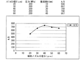
そこで、噴射ノズルの口径を50μmと一定にした場合において、50MPaから350MPaまでの圧力範囲で噴流の連続流領域の距離Aを測定し、A/Dの値を求め、図5(X軸:圧力MPa,Y軸:A/D)に示した。この圧力範囲は、これより低い圧力では噴射加工に必要なウォータジェットが得られず、この範囲を越える高圧力ではほとんど連続流領域(整流部)が確保できなくなり、ウォータージェット噴射加工として実用に適した噴流が得られる圧力範囲の実質的な上限および下限と言える。従って、この圧力範囲上限および下限におけるA/D値200、1300に基づいて噴射ノズルから噴射される噴流が連続流領域で絞りノズルへ導入され得るノズル間距離Aの実質的な範囲、即ち、ノズル口径Dの200倍から1300倍が特定される。
Therefore, when the diameter of the injection nozzle is fixed at 50 μm, the distance A of the continuous flow region of the jet is measured in the pressure range from 50 MPa to 350 MPa, and the value of A / D is obtained. FIG. MPa, Y axis: A / D). Water pressure required for injection processing cannot be obtained at pressures lower than this range, and a continuous flow region (rectifier) cannot be secured at high pressures exceeding this range, making it suitable for practical use as water jet injection processing. It can be said that it is a practical upper limit and a lower limit of the pressure range in which a jet can be obtained. Accordingly, a substantial range of the inter-nozzle distance A in which the jet flow injected from the injection nozzle based on the A /
また、本発明においては、噴射ノズルから噴射された噴流のうち、外方に拡散した領域で絞りノズルによって遮断された遮断水が噴射の時間経過に伴ってハウジング内に溜まって噴射形状を乱すことのないように、遮断水をハウジング外へ排出する排出水路を設けておくのが好ましい。 Further, in the present invention, of the jet flow injected from the injection nozzle, the blocking water blocked by the throttle nozzle in the region diffused outward accumulates in the housing as the injection time elapses and disturbs the injection shape. It is preferable to provide a drainage channel for discharging the blocking water to the outside of the housing.
さらに、この遮断水が効率よく排出されていくように、エアーアシスト機構を設けて排出水路内の遮断水をエアーで押し出す構成とすることがより好ましい。 Furthermore, it is more preferable that an air assist mechanism is provided so that the blocking water in the discharge channel is pushed out with air so that the blocking water is efficiently discharged.
また、被加工面は、表面に水滴が付着したり水膜が形成されたりすると、加工精度が悪くなるため、加工中に被加工面にエアーを吹き付けて水滴や水膜を吹き飛ばしたり付着を防止するためのエアーブローノズルを設けておくことが望ましい。 In addition, if water droplets adhere to the surface or a water film is formed on the surface to be processed, the processing accuracy will deteriorate, so air will be blown to the surface to be processed during processing to prevent water droplets or water films from blowing off or adhere to the surface. It is desirable to provide an air blow nozzle for this purpose.
本発明の一実施例としてのウォータジェットノズル装置を図1の概略構成図に示す。本ウォータジェットノズル装置は、被加工物上に配置されるハウジング1を装置本体として、鉛直下方に向けて高圧噴流を噴射するように噴射ノズル5と絞りノズル9とが同軸上に配置されてなるものである。
A water jet nozzle apparatus as an embodiment of the present invention is shown in the schematic block diagram of FIG. The present water jet nozzle apparatus has a
即ち、上部側で位置決め固定されているノズルアダプタ4の下端にノズルキャップ6の装着により噴射ノズル5が取り付けられ、このノズルアダプタ4に該アダプタ下部領域を内部に挿入した状態のハウジング1が、ガイドホルダ2を介して上下方向に相対位置調節可能に六角ボルト3により固定されている。
That is, the
さらに本装置では、このハウジング1には、下端に装着されたノズルホルダ8によって、噴射ノズル5の同軸上の流路7の端部側位置に絞りノズル9が取り付けられている。従って、外部から高圧ポンプ(不図示)によりノズルアダプタ4を介して供給され、噴射ノズル5によってノズルキャップ6に形成されている流路7へ噴射された超高圧水噴流は、所定の導入口径を有する絞りノズル9にコア部分のみが導入され、断面積の小さくなった加工用噴流として被加工面へ向けて噴射される。
Further, in this apparatus, a throttle nozzle 9 is attached to the
このとき、噴射ノズル5から噴射された噴流のうち、絞りノズル9に導入されないで遮断された外方領域の噴流水は、ハウジング1の内側に止まるが、本装置では、排出水路10を設けることによってこの遮断水をハウジング外へ排出する構成とし、遮断水がハウジング内に溜まって噴流の噴射形状を乱すのを防いでいる。また、この遮断水が効率よく排出されるように、排出水路内に溜まった水をエアーで押し出すように、ハウジング内へエアーを供給するエアーアシスト機構11を設けた。
At this time, out of the jets jetted from the
更に、本装置では、ハウジング1の外周部には、被加工面上にエアーを吹き付けるエアーノズル13と該エアーノズル13にエアーを供給するエアーチャンバ12を設けた。このエアーノズル13によるエアーの吹き付けで、被加工面上に加工精度を悪化させる水滴や水膜の付着を防ぐことができる。
Furthermore, in this apparatus, an
本装置では、ハウジング1は、ガイドホルダ2にボルト固定されており、このガイドホルダ2のノズルアダプタ4に対する六角ボルト3による固定部での位置調節により、ハウジング1およびその下端の絞りノズル9の位置調節を行うものであり、この位置調節により、絞りノズル9から噴射される加工用噴流が壊食溝加工に適した液滴流領域となるような噴射ノズル5に対する絞りノズル9の相対位置関係の条件を満たすように位置決めできる。
In this apparatus, the
以上の構成を備えた本ウォータジェットノズル装置を用いて、合金工具鋼(SKD61)に微細溝加工を施した結果を、従来の噴射ノズルのみを用いた場合と比較して以下に示す。加工条件は、本装置における絞りノズル9に関するもの以外、両者とも同じ設定とした。 The result of fine grooving on the alloy tool steel (SKD61) using the water jet nozzle device having the above-described configuration is shown below in comparison with the case where only the conventional injection nozzle is used. The processing conditions were the same for both, except for the diaphragm nozzle 9 in this apparatus.
即ち、上溝幅および表面ダレ領域100μm以下、溝深さ2.5mm以上を目標値として、噴射ノズルの噴射口径50μmで圧力350MPa、高圧水送り速度100mm/min、加工噴流距離(最終噴流の噴射位置から被加工面までの距離)20mm、噴射回数32パス、エアーアシスト圧0.2MPaという条件で、本実施例の装置では、噴射口径80μmの絞りノズル9を噴射ノズル5端から10mmの間隔で下方に位置決めした。
That is, with the upper groove width and surface sag region of 100 μm or less and groove depth of 2.5 mm or more as targets, the injection nozzle diameter is 50 μm, the pressure is 350 MPa, the high-pressure water feed speed is 100 mm / min, the processing jet distance (the injection position of the final jet) In the apparatus of the present embodiment, on the condition of 20 mm, the distance from the processing surface to 20 mm, the number of injections of 32 passes, and the air assist pressure of 0.2 MPa, the throttle nozzle 9 having an injection port diameter of 80 μm is moved downward from the end of the
以上の条件で本装置および従来型噴射ノズルで溝加工を行い、形成された溝の上溝幅L1、下溝幅L2、深さD、表面ダレ領域幅の寸法をそれぞれ測定し、結果を以下の表1にまとめた。 Groove processing was performed with this apparatus and the conventional injection nozzle under the above conditions, and the dimensions of the upper groove width L1, lower groove width L2, depth D, and surface sag region width of the formed groove were measured, and the results are shown in the following table. Summarized in 1.

表1に示すように、従来型の噴射ノズルによる溝加工では、上溝幅L1は、目標値に近いが、表面ダレ領域が非常に大きく、この表面ダレ領域を含む実質的な溝幅は、ほぼ目標値の3倍にもなっているのに対して、噴流ノズル5の同軸上の下流位置に絞りノズル9を備えた本ウォータジェットノズル装置による溝加工では、殆ど表面ダレを生じることなく、実質的な溝幅が100μm以下という加工がマスキングなしに可能であった。
As shown in Table 1, in the groove processing by the conventional injection nozzle, the upper groove width L1 is close to the target value, but the surface sag region is very large, and the substantial groove width including this surface sag region is approximately In contrast to the target value which is three times the target value, in the groove processing by the water jet nozzle device provided with the throttle nozzle 9 at the coaxial downstream position of the
なお、絞りノズルの噴射ノズルに対する距離は、実際に用いる噴射ノズルの噴射口径や噴射圧等の設定に応じて上記の両者の相対位置関係の条件を満たすように適宜設定すれば良い。 The distance between the throttle nozzle and the injection nozzle may be set as appropriate so as to satisfy the above-described relative positional relationship between the injection nozzle diameter and the injection pressure of the injection nozzle actually used.
1:ハウジング
2:ガイドホルダ
3:六角ボルト
4:ノズルアダプタ
5:噴射ノズル
6:ノズルキャップ
7:(噴流用)流路
8:ノズルホルダ
9:絞りノズル
10:排出水路
11:エアーアシスト機構
12:エアーチャンバ
13:エアーノズル
1: Housing 2: Guide holder 3: Hexagon bolt 4: Nozzle adapter 5: Injection nozzle 6: Nozzle cap 7: (For jet) Channel 8: Nozzle holder 9: Restriction nozzle 10: Discharge water channel 11: Air assist mechanism 12: Air chamber 13: Air nozzle
Claims (4)
該噴射ノズルと同軸上の前記流路の端部側に設置され、前記噴射ノズルから噴射された噴流を導入して被加工面に向けて噴射する絞りノズルと、
前記噴射ノズルから噴射された噴流のうち、前記絞りノズルに導入されないで遮断された遮断水をハウジング外に排出する排出水路と、を備えたことを特徴とするウォータジェットノズル装置。 An injection nozzle installed inside the housing and injecting a jet of ultra-high pressure water into a flow path formed in the housing;
A throttle nozzle that is installed on the end side of the flow path coaxial with the injection nozzle, introduces a jet flow injected from the injection nozzle, and injects it toward the processing surface ;
A water jet nozzle device comprising: a discharge water passage for discharging a shut-off water, which is shut off without being introduced into the throttling nozzle, out of the jet jet jetted from the jet nozzle.
Priority Applications (1)
| Application Number | Priority Date | Filing Date | Title |
|---|---|---|---|
| JP2005083767A JP4484739B2 (en) | 2005-03-23 | 2005-03-23 | Water jet nozzle device |
Applications Claiming Priority (1)
| Application Number | Priority Date | Filing Date | Title |
|---|---|---|---|
| JP2005083767A JP4484739B2 (en) | 2005-03-23 | 2005-03-23 | Water jet nozzle device |
Publications (2)
| Publication Number | Publication Date |
|---|---|
| JP2006263547A JP2006263547A (en) | 2006-10-05 |
| JP4484739B2 true JP4484739B2 (en) | 2010-06-16 |
Family
ID=37200074
Family Applications (1)
| Application Number | Title | Priority Date | Filing Date |
|---|---|---|---|
| JP2005083767A Expired - Fee Related JP4484739B2 (en) | 2005-03-23 | 2005-03-23 | Water jet nozzle device |
Country Status (1)
| Country | Link |
|---|---|
| JP (1) | JP4484739B2 (en) |
Families Citing this family (3)
| Publication number | Priority date | Publication date | Assignee | Title |
|---|---|---|---|---|
| JP4523484B2 (en) * | 2005-05-23 | 2010-08-11 | 株式会社丸山製作所 | Spray nozzle |
| KR101214095B1 (en) * | 2010-07-14 | 2012-12-20 | 이영남 | Nozzle module of sand blasting apparatus without stencil |
| CN106000693B (en) * | 2016-07-20 | 2018-08-31 | 朱庭春 | It is a kind of mutually swash wash away nozzle |
Citations (2)
| Publication number | Priority date | Publication date | Assignee | Title |
|---|---|---|---|---|
| JP2000049062A (en) * | 1998-07-27 | 2000-02-18 | Canon Inc | Device and method for dividing sample |
| JP2001198829A (en) * | 2000-01-11 | 2001-07-24 | Uingu:Kk | Water jet device for cutting |
Family Cites Families (1)
| Publication number | Priority date | Publication date | Assignee | Title |
|---|---|---|---|---|
| JPH06320104A (en) * | 1993-05-14 | 1994-11-22 | Shiyuunan Chiiki Jiba Sangyo Shinko Center | Production of industrial art object equipped with different painting pattern |
-
2005
- 2005-03-23 JP JP2005083767A patent/JP4484739B2/en not_active Expired - Fee Related
Patent Citations (2)
| Publication number | Priority date | Publication date | Assignee | Title |
|---|---|---|---|---|
| JP2000049062A (en) * | 1998-07-27 | 2000-02-18 | Canon Inc | Device and method for dividing sample |
| JP2001198829A (en) * | 2000-01-11 | 2001-07-24 | Uingu:Kk | Water jet device for cutting |
Also Published As
| Publication number | Publication date |
|---|---|
| JP2006263547A (en) | 2006-10-05 |
Similar Documents
| Publication | Publication Date | Title |
|---|---|---|
| TWI391202B (en) | A laser processing apparatus, a manufacturing method of a laser processing apparatus, and a laser processing method | |
| JP4581910B2 (en) | Hole surface processing method | |
| WO2010122851A1 (en) | Blasting apparatus and method for blasting | |
| TWI551382B (en) | Fine hole discharge processing device | |
| JPWO2015060043A1 (en) | Blasting method and blasting apparatus | |
| CA2485118A1 (en) | Descaling nozzle | |
| WO2012048047A1 (en) | Piercing and/or cutting devices for abrasive waterjet systems and associated systems and methods | |
| JP2009233784A (en) | Method of reducing waterjet injection sound | |
| JP2008307624A (en) | Apparatus and method for deburring and cleaning | |
| JP4484739B2 (en) | Water jet nozzle device | |
| JP2009113106A (en) | Laser beam machining apparatus | |
| JP2003053644A (en) | Machine tool and lubricant jetting state detecting device for machine tool | |
| JP2010234373A (en) | Laser machining nozzle, and laser machining apparatus | |
| JP2003048160A (en) | Minute groove machining method and device therefor | |
| TWI441716B (en) | Spray nozzles for jetting | |
| CN109789513B (en) | Laser cutting nozzle, laser machining device with nozzle and operation method thereof | |
| JP2942168B2 (en) | Method and apparatus for enlarging processing pattern in blast processing | |
| JP6205753B2 (en) | Gas wiping nozzle and gas wiping method | |
| JP4758691B2 (en) | spray nozzle | |
| JPH04372399A (en) | Water jet cutting device | |
| US10518385B2 (en) | Apparatus and process for surface treating interior of a workpiece | |
| JPH0899051A (en) | Atomized substance supplying apparatus | |
| KR102577058B1 (en) | Water-jet processing apparatus for grainding surface | |
| JP2003251561A (en) | Grinding method and grinding device | |
| JPS61241067A (en) | Blasting device |
Legal Events
| Date | Code | Title | Description |
|---|---|---|---|
| A621 | Written request for application examination |
Free format text: JAPANESE INTERMEDIATE CODE: A621 Effective date: 20070207 |
|
| A131 | Notification of reasons for refusal |
Free format text: JAPANESE INTERMEDIATE CODE: A131 Effective date: 20091224 |
|
| A521 | Written amendment |
Free format text: JAPANESE INTERMEDIATE CODE: A523 Effective date: 20100222 |
|
| TRDD | Decision of grant or rejection written | ||
| A01 | Written decision to grant a patent or to grant a registration (utility model) |
Free format text: JAPANESE INTERMEDIATE CODE: A01 Effective date: 20100317 |
|
| A01 | Written decision to grant a patent or to grant a registration (utility model) |
Free format text: JAPANESE INTERMEDIATE CODE: A01 |
|
| A61 | First payment of annual fees (during grant procedure) |
Free format text: JAPANESE INTERMEDIATE CODE: A61 Effective date: 20100323 |
|
| R150 | Certificate of patent or registration of utility model |
Free format text: JAPANESE INTERMEDIATE CODE: R150 |
|
| FPAY | Renewal fee payment (event date is renewal date of database) |
Free format text: PAYMENT UNTIL: 20130402 Year of fee payment: 3 |
|
| LAPS | Cancellation because of no payment of annual fees |