JP4484635B2 - Spiral type reverse osmosis membrane element and manufacturing method thereof - Google Patents
Spiral type reverse osmosis membrane element and manufacturing method thereof Download PDFInfo
- Publication number
- JP4484635B2 JP4484635B2 JP2004255779A JP2004255779A JP4484635B2 JP 4484635 B2 JP4484635 B2 JP 4484635B2 JP 2004255779 A JP2004255779 A JP 2004255779A JP 2004255779 A JP2004255779 A JP 2004255779A JP 4484635 B2 JP4484635 B2 JP 4484635B2
- Authority
- JP
- Japan
- Prior art keywords
- reverse osmosis
- spiral
- membrane element
- osmosis membrane
- porous support
- Prior art date
- Legal status (The legal status is an assumption and is not a legal conclusion. Google has not performed a legal analysis and makes no representation as to the accuracy of the status listed.)
- Expired - Lifetime
Links
Images

Classifications
-
- B—PERFORMING OPERATIONS; TRANSPORTING
- B01—PHYSICAL OR CHEMICAL PROCESSES OR APPARATUS IN GENERAL
- B01D—SEPARATION
- B01D63/00—Apparatus in general for separation processes using semi-permeable membranes
- B01D63/10—Spiral-wound membrane modules
- B01D63/101—Spiral winding
-
- B—PERFORMING OPERATIONS; TRANSPORTING
- B01—PHYSICAL OR CHEMICAL PROCESSES OR APPARATUS IN GENERAL
- B01D—SEPARATION
- B01D61/00—Processes of separation using semi-permeable membranes, e.g. dialysis, osmosis or ultrafiltration; Apparatus, accessories or auxiliary operations specially adapted therefor
- B01D61/02—Reverse osmosis; Hyperfiltration ; Nanofiltration
- B01D61/025—Reverse osmosis; Hyperfiltration
-
- B—PERFORMING OPERATIONS; TRANSPORTING
- B01—PHYSICAL OR CHEMICAL PROCESSES OR APPARATUS IN GENERAL
- B01D—SEPARATION
- B01D65/00—Accessories or auxiliary operations, in general, for separation processes or apparatus using semi-permeable membranes
- B01D65/003—Membrane bonding or sealing
-
- B—PERFORMING OPERATIONS; TRANSPORTING
- B01—PHYSICAL OR CHEMICAL PROCESSES OR APPARATUS IN GENERAL
- B01D—SEPARATION
- B01D67/00—Processes specially adapted for manufacturing semi-permeable membranes for separation processes or apparatus
- B01D67/0081—After-treatment of organic or inorganic membranes
- B01D67/0088—Physical treatment with compounds, e.g. swelling, coating or impregnation
-
- B—PERFORMING OPERATIONS; TRANSPORTING
- B01—PHYSICAL OR CHEMICAL PROCESSES OR APPARATUS IN GENERAL
- B01D—SEPARATION
- B01D69/00—Semi-permeable membranes for separation processes or apparatus characterised by their form, structure or properties; Manufacturing processes specially adapted therefor
- B01D69/10—Supported membranes; Membrane supports
- B01D69/107—Organic support material
- B01D69/1071—Woven, non-woven or net mesh
-
- B—PERFORMING OPERATIONS; TRANSPORTING
- B01—PHYSICAL OR CHEMICAL PROCESSES OR APPARATUS IN GENERAL
- B01D—SEPARATION
- B01D69/00—Semi-permeable membranes for separation processes or apparatus characterised by their form, structure or properties; Manufacturing processes specially adapted therefor
- B01D69/12—Composite membranes; Ultra-thin membranes
- B01D69/1213—Laminated layers
-
- B—PERFORMING OPERATIONS; TRANSPORTING
- B01—PHYSICAL OR CHEMICAL PROCESSES OR APPARATUS IN GENERAL
- B01D—SEPARATION
- B01D69/00—Semi-permeable membranes for separation processes or apparatus characterised by their form, structure or properties; Manufacturing processes specially adapted therefor
- B01D69/12—Composite membranes; Ultra-thin membranes
- B01D69/1216—Three or more layers
-
- B—PERFORMING OPERATIONS; TRANSPORTING
- B01—PHYSICAL OR CHEMICAL PROCESSES OR APPARATUS IN GENERAL
- B01D—SEPARATION
- B01D2313/00—Details relating to membrane modules or apparatus
- B01D2313/04—Specific sealing means
- B01D2313/042—Adhesives or glues
-
- B—PERFORMING OPERATIONS; TRANSPORTING
- B01—PHYSICAL OR CHEMICAL PROCESSES OR APPARATUS IN GENERAL
- B01D—SEPARATION
- B01D2323/00—Details relating to membrane preparation
- B01D2323/12—Specific ratios of components used
-
- B—PERFORMING OPERATIONS; TRANSPORTING
- B01—PHYSICAL OR CHEMICAL PROCESSES OR APPARATUS IN GENERAL
- B01D—SEPARATION
- B01D2325/00—Details relating to properties of membranes
- B01D2325/04—Characteristic thickness
-
- B—PERFORMING OPERATIONS; TRANSPORTING
- B01—PHYSICAL OR CHEMICAL PROCESSES OR APPARATUS IN GENERAL
- B01D—SEPARATION
- B01D2325/00—Details relating to properties of membranes
- B01D2325/26—Electrical properties
Landscapes
- Chemical & Material Sciences (AREA)
- Chemical Kinetics & Catalysis (AREA)
- Engineering & Computer Science (AREA)
- Water Supply & Treatment (AREA)
- Nanotechnology (AREA)
- Inorganic Chemistry (AREA)
- Manufacturing & Machinery (AREA)
- Separation Using Semi-Permeable Membranes (AREA)
Description
本発明は、液体中に浮遊及び溶存している成分を分離するスパイラル型逆浸透膜エレメントに関し、より詳しくは、供給側流体と透過側流体の混合を防ぐための封止部を接着剤により形成する際に、微小リークを低減できるスパイラル型逆浸透膜エレメント及びその製造方法に関する。 The present invention relates to a spiral reverse osmosis membrane element that separates components suspended and dissolved in a liquid, and more specifically, a sealing portion for preventing mixing of a supply side fluid and a permeation side fluid is formed by an adhesive. The present invention relates to a spiral-type reverse osmosis membrane element that can reduce microleakage and a method for manufacturing the same.
従来より、逆浸透ろ過、限外ろ過、精密ろ過等に用いられる流体分離エレメントとして、例えば、供給側流体を分離膜表面へ導く供給側流路材、供給側流体を分離する分離膜、分離膜を透過し供給側流体から分離された透過側流体を中心管へと導く透過側流路材からなるユニットを有孔の中心管の周りに巻き付けたスパイラル型膜エレメントが知られている。 Conventionally, as a fluid separation element used for reverse osmosis filtration, ultrafiltration, microfiltration, etc., for example, a supply-side channel material that guides the supply-side fluid to the surface of the separation membrane, a separation membrane that separates the supply-side fluid, and a separation membrane There is known a spiral membrane element in which a unit made of a permeate-side flow channel material that permeates through and separates a permeate-side fluid separated from a supply-side fluid to a central tube is wound around a perforated central tube.
このようなスパイラル型膜エレメントは、一般的に分離膜を二つ折りにした間に供給側流路材を配置したものと、透過側流路材とを積み重ね、供給側流体と透過側流体の混合を防ぐ封止部を形成するため接着剤を分離膜周辺部(3辺)に塗布して分離膜ユニットを作製し、このユニットの単数または複数を中心管の周囲にスパイラル状に巻きつけて、更に分離膜周辺部を封止することによって製造される。 Such a spiral membrane element generally has a structure in which a supply-side channel material is arranged while a separation membrane is folded in two and a permeation-side channel material, and the supply-side fluid and permeation-side fluid are mixed. In order to form a sealing portion to prevent the separation membrane unit (3 sides) is applied to the separation membrane peripheral portion to produce a separation membrane unit, and one or more of the units are spirally wound around the central tube, Further, it is manufactured by sealing the periphery of the separation membrane.
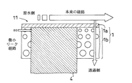
封止方法については、例えば下記特許文献1には、ホットメルトタイプのテープ状接着剤を用いて封止し、仮固定した上で電磁波を照射することにより分離膜周辺部を接着する方法が開示されている。しかしこの方法では、分離膜内部に接着剤が十分に含浸しないため、透過側流路と供給側流路を完全に分離することができず、原水が透過側に流れるのを十分に防ぐことができない。即ち、図5に示すように、分離膜101への接着剤102の含浸が不十分な部分に多孔質層101bが残ることにより、分離膜101の外面に沿って流れるべき原液の一部が、この多孔質層101bを通り、水平方向に分離膜101の内部に流入し、透過側へ混入する。
As for the sealing method, for example, the following
また、多量の接着剤を用いることで原水が透過することを防ぐ方法もある。しかし、接着剤の量を必要以上に多くすると接着剤の厚みにムラができ、シワが発生し易いなど、膜リーフを中空管に巻きつけるときの障害になることも問題であった。
本発明は、前記の従来の問題点に鑑みなされたものであり、その目的は、接着剤等の封止樹脂を十分に含浸し得る構造の不織布層を用いること等により膜リーフ端部に於ける封止樹脂の含浸性を改善し、微小リークを効果的に防止可能なスパイラル型逆浸透膜エレメント、及びその製造方法を提供することにある。 The present invention has been made in view of the above-mentioned conventional problems, and its purpose is to use a nonwoven fabric layer having a structure that can be sufficiently impregnated with a sealing resin such as an adhesive at the end of the membrane leaf. An object of the present invention is to provide a spiral-type reverse osmosis membrane element that can improve the impregnation property of sealing resin and effectively prevent minute leaks, and a method for manufacturing the same.
本願発明者等は、前記従来の問題点を解決すべく、スパイラル型逆浸透膜エレメント、その製造方法及びその使用方法について鋭意検討した。その結果、下記の構成を採用することにより前記の目的を達成できることを見出して、本発明を完成させるに至った。 In order to solve the above-mentioned conventional problems, the inventors of the present application have made extensive studies on a spiral type reverse osmosis membrane element, a method for producing the element, and a method for using the element. As a result, the inventors have found that the above object can be achieved by adopting the following configuration, and have completed the present invention.
即ち、前記の課題を解決する為に、本発明に係るスパイラル型逆浸透膜エレメントは、分離膜と供給側流路材と透過側流路材とが積層状態で有孔の中心管の周囲にスパイラル状に巻回された円筒状巻回体を備えると共に、供給側流体と透過側流体の混合を防ぐための封止部が設けられているスパイラル型逆浸透膜エレメントであって、前記透過側流路材を介して対向する分離膜は、不織布層上に多孔性支持体及びスキン層が順次積層された構造を有し、前記分離膜の縁部には封止樹脂により封止された封止部が設けられており、前記封止樹脂は、多孔性支持体に於いてスキン層まで含浸されており、前記不織布層の外側面、及び不織布層が複数層からなる場合には各層間には、前記封止樹脂の含浸を阻害するバリア部が設けられておらず、かつ、前記不織布層の前記多孔性支持体と接する側には、当該多孔性支持体を構成するポリマーが3〜6g/m 2 の含浸量で含浸されていることを特徴とする。 That is, in order to solve the above-described problem, the spiral reverse osmosis membrane element according to the present invention includes a separation membrane, a supply-side channel material, and a permeation-side channel material laminated around a perforated central tube. A spiral reverse osmosis membrane element comprising a cylindrical wound body wound in a spiral shape and provided with a sealing portion for preventing mixing of a supply side fluid and a permeate side fluid, wherein the permeate side The separation membrane facing through the channel material has a structure in which a porous support and a skin layer are sequentially laminated on a non-woven fabric layer, and the edge of the separation membrane is sealed with a sealing resin. Stops are provided, and the sealing resin is impregnated up to the skin layer in the porous support , and when the nonwoven fabric layer is composed of a plurality of layers, the outer surface of the nonwoven fabric layer is interposed between the layers. Is not provided with a barrier part that impedes impregnation of the sealing resin, , The side contacting the porous support of the non-woven layer, characterized in that the polymer constituting the porous support is impregnated with an impregnating amount of 3 to 6 g / m 2.
前記の構成によれば、封止樹脂が少なくともスキン層の近傍まで含浸されているので、封止部のシール効果を向上させ、これにより供給側流路から透過側流路に原流体が微小リークするのを効果的に防止できる。その結果、分離対象物質(例えば、粒子や塩等)の阻止率を向上させスパイラル型逆浸透膜エレメントとしての分離性能の向上が図れる。 According to the above configuration, the sealing resin is impregnated to at least the vicinity of the skin layer, so that the sealing effect of the sealing portion is improved, and thereby the raw fluid leaks from the supply side flow path to the permeation side flow path. Can be effectively prevented. As a result, it is possible to improve the separation performance as a spiral type reverse osmosis membrane element by improving the rejection rate of substances to be separated (for example, particles and salts).
また、前記不織布層には前記多孔性支持体を構成するポリマーが含浸されており、該ポリマーの含浸量は3〜6g/mThe nonwoven fabric layer is impregnated with a polymer constituting the porous support, and the impregnation amount of the polymer is 3 to 6 g / m. 22 である。It is.
前記構成のように含浸量3〜6g/mImpregnation amount 3-6g / m as in the above configuration 22 のポリマーが不織布層のスキン層側に含有されていると、封止樹脂を含浸させる際にポリマーとの接触により含浸が促進されるので、不織布層に封止樹脂が十分に含浸された分離膜が得られる。When the polymer is contained on the skin layer side of the nonwoven fabric layer, the impregnation is promoted by contact with the polymer when impregnating the sealing resin. Therefore, the separation membrane in which the nonwoven fabric layer is sufficiently impregnated with the sealing resin Is obtained.
また、前記不織布層の外側面、及び不織布層が複数層からなる場合には各層間に封止樹脂の含浸を阻害するバリア部が設けられていない。In addition, when the nonwoven fabric layer is formed of a plurality of layers, a barrier portion that inhibits impregnation of the sealing resin is not provided between the respective layers.
不織布層の外側面や、不織布層が複数層からなる場合には各層間に、封止樹脂の含浸の障害となるバリア部が存在すると、該不織布層に対する封止樹脂の含浸の障壁となる。しかし、前記構成のようにバリア部が設けられない構成であると、少なくともスキン層の近傍まで封止樹脂を十分に含浸させた分離膜を実現することができる。If the outer surface of the nonwoven fabric layer or the nonwoven fabric layer comprises a plurality of layers, if there is a barrier portion that impedes the impregnation of the sealing resin between the respective layers, the nonwoven fabric layer becomes a barrier against the impregnation of the sealing resin. However, when the barrier portion is not provided as in the above configuration, it is possible to realize a separation membrane sufficiently impregnated with the sealing resin at least to the vicinity of the skin layer.
また、前記分離膜に、濃度32,000ppmのNaCl水溶液を供給側流体として5.5MPaの操作圧力で供給し、かつ透過水の回収率を8〜12%と設定した場合に、前記封止部近傍に於ける透過水の電気伝導率が、それ以外の領域に於ける透過水の電気伝導率に対し2倍以下であることが好ましい。 Further, when the NaCl aqueous solution having a concentration of 32,000 ppm is supplied to the separation membrane as a supply side fluid at an operating pressure of 5.5 MPa, and the recovery rate of permeated water is set to 8 to 12%, the sealing portion It is preferable that the electric conductivity of the permeated water in the vicinity is not more than twice the electric conductivity of the permeated water in other regions.
前記の構成によれば、前記条件下でNaCl水溶液の分離操作を行うと、封止部近傍に於ける透過水の電気伝導率が、それ以外の領域に於ける透過水の電気伝導率に対し2倍以下となる。よって、前記構成とすることにより、NaCl水溶液を良好な塩阻止率でNaClと透過水とに分離することが可能なスパイラル型逆浸透膜エレメントを提供できる。 According to the above configuration, when the NaCl aqueous solution is separated under the above conditions, the electric conductivity of the permeated water in the vicinity of the sealing portion is smaller than the electric conductivity of the permeated water in the other regions. 2 times or less. Therefore, the spiral reverse osmosis membrane element capable of separating the NaCl aqueous solution into NaCl and permeated water with a good salt rejection can be provided by the above configuration.
前記不織布層の平均孔径は8〜12μmであり、かつ平均孔径と最大孔径の比(最大孔径/平均孔径)は1〜4であることが好ましい。 The nonwoven fabric layer preferably has an average pore diameter of 8 to 12 μm and a ratio of the average pore diameter to the maximum pore diameter (maximum pore diameter / average pore diameter) of 1 to 4.
不織布層の平均孔径を前記範囲内とすることにより、封止樹脂が不織布層に含浸するのを容易にし、かつ毛管作用効果も最適なものにする。その結果、封止樹脂が少なくともスキン層の近傍まで含浸した分離膜が得られる。また、平均孔径と最大孔径の比を1〜4とすることにより、不織布層の面内に於ける封止樹脂の含浸性を均一にすることができ、ムラの発生を低減することができる。
By setting the average pore diameter of the nonwoven fabric layer within the above range, the sealing resin can be easily impregnated into the nonwoven fabric layer, and the capillary action effect can be optimized. As a result, a separation membrane in which the sealing resin is impregnated to at least the vicinity of the skin layer is obtained. Moreover, by making the ratio of the average pore diameter and the
また、前記多孔性支持体の厚さは30〜60μmであることが好ましい。 Moreover, it is preferable that the thickness of the said porous support body is 30-60 micrometers.
前記構成であると、封止樹脂の含浸に対する抵抗を低減すると共に、膜欠陥が増大するのを防止することができる。 With this configuration, resistance to impregnation of the sealing resin can be reduced and film defects can be prevented from increasing.
また、前記分離膜は、前記封止部のスキン層側に於ける面の画像データをしきい値230で二値化処理した場合に、処理後の画像データの黒レベルが60%以上となるまで前記ポリマーを前記多孔性支持体に含浸したものであることが好ましい。 Further, when the image data of the surface of the sealing portion on the skin layer side is binarized with the threshold value 230, the black level of the processed image data becomes 60% or more. It is preferable that the porous support is impregnated with the polymer.
前記構成のように、封止部のスキン層側に於ける面の画像データに於いて、二値化処理後の黒レベルが60%以上となる様にポリマーをスキン層に含浸させると、封止樹脂の不織布層に対する含浸性を良好なものにすることができる。その結果、供給側流路から透過側流路への原流体の微小リークを一層防止することができる。 When the skin layer is impregnated with a polymer so that the black level after binarization processing is 60% or more in the image data of the surface on the skin layer side of the sealing portion as in the above configuration, the sealing is performed. The impregnation property with respect to the nonwoven fabric layer of a stop resin can be made favorable. As a result, it is possible to further prevent a minute leak of the raw fluid from the supply side channel to the permeate side channel.
また、前記分離膜は、前記封止部の不織布層側に於ける面のヘイズ値が20%以上になるまで前記ポリマーを前記多孔性支持体に含浸したものであることが好ましい。 Moreover, it is preferable that the said separation membrane is what impregnated the said polymer to the said porous support until the haze value of the surface in the nonwoven fabric layer side of the said sealing part will be 20% or more.
前記構成のように、封止部のスキン層側に於ける面のヘイズ値が20%以上となる様にポリマーをスキン層に含浸させると、封止樹脂の不織布層に対する含浸性を良好なものにすることができる。その結果、供給側流路から透過側流路への原流体の微小リークを一層防止することができる。 When the polymer is impregnated into the skin layer so that the haze value of the surface on the skin layer side of the sealing portion is 20% or more as in the above-described configuration, the impregnation property of the sealing resin to the nonwoven fabric layer is good. Can be. As a result, it is possible to further prevent a minute leak of the raw fluid from the supply side channel to the permeate side channel.
前記の課題を解決する為に、本発明に係るスパイラル型逆浸透膜エレメントの製造方法は、不織布層上に多孔性支持体及びスキン層が順次積層された分離膜と供給側流路材と透過側流路材とが積層状態で有孔の中心管の周囲にスパイラル状に巻回された円筒状巻回体を備えると共に、供給側流体と透過側流体の混合を防ぐための封止部が設けられているスパイラル型逆浸透膜エレメントの製造方法であって、前記不織布層上に前記多孔性支持体を構成するポリマーを塗布し、かつ、当該ポリマーを含浸量が3〜6g/m2の範囲内になる様に含浸させた後、乾燥させて多孔性支持体を形成する工程と、前記多孔性支持体上にスキン層を製膜して分離膜を形成する工程と、前記分離膜と供給側流路材と透過側流路材とを積層状態で有孔の中心管の周囲にスパイラル状に巻回して円筒状巻回体を形成する工程と、前記供給側流体と透過側流体の混合を防ぐため、透過側流路材を介して対向する分離膜の縁部に、多孔性支持体側から封止樹脂を塗布し、かつ封止樹脂をスキン層まで含浸させて封止する工程とを有し、前記不織布層として、その外側面、及び不織布層が複数層からなる場合には各層間に、前記封止樹脂の含浸を阻害するバリア部が設けられていないものを使用することを特徴とする。
In order to solve the above-described problems, a method for manufacturing a spiral reverse osmosis membrane element according to the present invention includes a separation membrane in which a porous support and a skin layer are sequentially laminated on a nonwoven fabric layer , a supply-side flow path material, and a permeation membrane. A cylindrical wound body spirally wound around the perforated central tube in a laminated state with the side channel material, and a sealing portion for preventing mixing of the supply side fluid and the permeate side fluid A method for producing a spiral reverse osmosis membrane element, wherein a polymer constituting the porous support is applied onto the nonwoven fabric layer, and the impregnation amount of the polymer is in the range of 3 to 6 g /
前記の方法によれば、多孔性支持体側から封止樹脂を塗布し、かつ封止樹脂を少なくともスキン層の近傍にまで含浸させて封止する工程を含むので、分離膜に於ける供給側流路から透過側流路に原流体が微小リークするのを効果的に防止した分離膜を備えるスパイラル型逆浸透膜エレメントが得られる。即ち、前記の方法によれば、微小リークを効果的に防止し、分離対象物質の阻止率を向上させたスパイラル型逆浸透膜エレメントを製造することができる。 According to the above method, since the sealing resin is applied from the porous support side and the sealing resin is impregnated at least near the skin layer and sealed, the supply side flow in the separation membrane is included. A spiral type reverse osmosis membrane element having a separation membrane that effectively prevents the raw fluid from minutely leaking from the channel to the permeate side channel is obtained. That is, according to the above method, it is possible to manufacture a spiral reverse osmosis membrane element that effectively prevents minute leaks and improves the rejection rate of the substance to be separated.
また、前記分離膜の形成工程の前に、2以上の反応性のアミノ基を有する多官能性アミノ化合物を含む溶液を調製する工程と、2以上の反応性の酸ハライド基を有する多官能性酸ハライド化合物を含む溶液を調製する工程とを行い、前記分離膜の形成工程は、前記多官能性アミノ化合物と多官能性酸ハライド化合物とを界面重合させ前記スキン層としてのポリアミド層を形成する工程であることが好ましい。 In addition, before the separation membrane forming step, a step of preparing a solution containing a polyfunctional amino compound having two or more reactive amino groups, and a polyfunctionality having two or more reactive acid halide groups Preparing a solution containing an acid halide compound, and forming the separation membrane by interfacially polymerizing the polyfunctional amino compound and the polyfunctional acid halide compound to form a polyamide layer as the skin layer. It is preferable that it is a process.
また、前記封止樹脂として、その粘度が10〜40Pa・sの範囲内のものを使用することが好ましい。 Moreover, it is preferable to use the sealing resin having a viscosity in the range of 10 to 40 Pa · s.
前記方法であると、多孔性支持体に封止樹脂を塗布したときに、液だれによって塗布した領域以外の領域に含浸するのを防止できる。また、多孔性支持体に対する封止樹脂の含浸性も良好となり、少なくともスキン層の近傍まで封止樹脂を到達させることが可能となる。その結果、微小リークを効果的に防止し、分離性能に優れたスパイラル型逆浸透膜エレメントを歩留まり良く製造することができる。 According to the above method, when the sealing resin is applied to the porous support, it is possible to prevent impregnation in a region other than the region applied by dripping. Moreover, the impregnation property of the sealing resin with respect to the porous support is improved, and the sealing resin can reach at least the vicinity of the skin layer. As a result, a spiral reverse osmosis membrane element that effectively prevents minute leaks and has excellent separation performance can be manufactured with high yield.
本発明は、前記に説明した手段により、以下の効果を奏する。
即ち、本発明によれば、封止樹脂を分離膜に於けるスキン層の少なくとも近傍にまで含浸させることにより、封止部のシール性を向上させる。その結果、供給側流路から透過側流路に原流体が微小リークするのを効果的に防止することができ、分離対象物質の阻止率を向上させて分離性能を良好なものとすることができる。
The present invention has the following effects by the means described above.
That is, according to the present invention, the sealing property of the sealing portion is improved by impregnating the sealing resin to at least the vicinity of the skin layer in the separation membrane. As a result, it is possible to effectively prevent the raw fluid from minutely leaking from the supply side channel to the permeate side channel, and to improve the rejection rate of the substance to be separated and to improve the separation performance. it can.
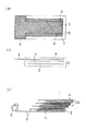
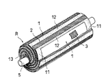
本発明の実施の形態について、図を参照しながら以下に説明する。図1(a)〜1(c)は、本発明のスパイラル型逆浸透膜エレメントの製造方法の一例を示す工程図である。図2は、本発明のスパイラル型逆浸透膜エレメントの一例を示す部分破断した斜視図である。尚、説明に不要な部分は省略し、また説明を容易にする為に拡大または縮小等して図示した部分がある。以上のことは、以下の図面に対しても同様である。 Embodiments of the present invention will be described below with reference to the drawings. 1A to 1C are process diagrams showing an example of a method for producing a spiral reverse osmosis membrane element of the present invention. FIG. 2 is a partially broken perspective view showing an example of the spiral reverse osmosis membrane element of the present invention. It should be noted that portions not necessary for the description are omitted, and there are portions illustrated in an enlarged or reduced manner for easy explanation. The same applies to the following drawings.
本発明のスパイラル型逆浸透膜エレメントは、図1〜図2に示すように、分離膜1、供給側流路材2、及び透過側流路材3が、積層状態で有孔の中心管5の周囲にスパイラル状に巻回された円筒状巻回体Rを備えると共に、供給側流体と透過側流体の混合を防ぐための封止部が設けられている。封止部には、両端封止部11と外周側封止部12が含まれる。
1-2, the spiral reverse osmosis membrane element of the present invention comprises a perforated
図2に示すように、透過側流路材3を介して対向する分離膜1の両端は両端封止部11により封止され、スパイラル状に配置された複数の両端封止部11の間には、供給側流路材2が介在する。また、透過側流路材3を介して対向する分離膜1の外周側端部は、軸方向に沿った外周側封止部12により封止されている。
As shown in FIG. 2, both ends of the
上記の円筒状巻回体Rは、分離膜1と供給側流路材2と透過側流路材3とを積層状態で有孔の中心管5の周囲にスパイラル状に巻回して円筒状巻回体Rを形成する工程と、供給側流体と透過側流体の混合を防ぐための封止部を形成する工程とによって製造することができる。具体的には、例えば図1に示す実施形態により製造することができる。図1(a)は分離膜ユニットUの平面図であり、図1(b)は分離膜ユニットUの正面図であり、図1(c)は分離膜ユニットUを積層して巻回する前の状態を示す正面図である。
The cylindrical wound body R is formed by spirally winding the
まず、図1(a)及び1(b)に示すように、分離膜1を二つ折りにした間に供給側流路材2を配置したものと透過側流路材3とを積み重ね、供給流体と透過流体の混合を防ぐ封止部11、12を形成するための接着剤4、6を、透過側流路材3の軸方向両端部及び巻回終端部に塗布した分離膜ユニットUを準備する。このとき、分離膜1の折り目部分に保護テープを貼り付けてもよい。
First, as shown in FIGS. 1 (a) and 1 (b), the supply-side
分離膜1は、不織布層上に多孔性支持体及びスキン層(緻密層)が順次積層された構造である。不織布層の構成材料としては特に限定されるものではなく、従来公知のものを採用することができる。具体的には、例えばポリエステル、ポリオレフィン等を例示できる。また、前記不織布層は、単層からなることが好ましい。ただし、複数層からなる不織布層も本発明では適用可能である。この場合、各層の表面は、カレンダーロール等で熱や圧力を加えられていないことが好ましい。例えば、熱加工されると、各層の表面孔が溶融することで収縮し、熱溶融した表層部分が緻密な層となって封止樹脂の含浸を阻害する障壁(バリア部)となるからである。
The
前記不織布層の平均孔径は8〜12μmであることが好ましく、9〜10μmであることがより好ましい。前記範囲内であると、封止樹脂を少なくともスキン層の近傍まで含浸させることが可能になるからである。平均孔径が8μmより小さい場合、封止樹脂は付着濡れの状態となって不織布層への含浸が困難となる傾向がある。その一方、平均孔径が12μmより大きい場合、封止樹脂が不織布層に含浸する際の毛管作用効果が小さくなり、含浸が不十分となる傾向がある。 The average pore size of the nonwoven fabric layer is preferably 8 to 12 μm, and more preferably 9 to 10 μm. It is because it becomes possible to impregnate sealing resin at least to the vicinity of a skin layer as it is in the said range. When the average pore diameter is smaller than 8 μm, the sealing resin tends to be in a wet-attached state, making it difficult to impregnate the nonwoven fabric layer. On the other hand, when the average pore diameter is larger than 12 μm, the capillary action effect when the sealing resin impregnates the nonwoven fabric layer becomes small, and the impregnation tends to be insufficient.
また、不織布層に於ける平均孔径と最大孔径の比(最大孔径/平均孔径)は1〜4であることが好ましく、1〜3であることがより好ましい。前記範囲内であると、不織布層の面内に於ける封止樹脂の含浸性を均一にすることができ、ムラの発生を低減することができる。 Further, the ratio of the average pore diameter to the maximum pore diameter (maximum pore diameter / average pore diameter) in the nonwoven fabric layer is preferably 1 to 4, and more preferably 1 to 3. Within the above range, the impregnation property of the sealing resin in the plane of the nonwoven fabric layer can be made uniform, and the occurrence of unevenness can be reduced.
不織布層の厚さ(複数層の場合は、全厚)は特に限定されるものではないが、80〜120μmであることが望ましく、90〜110μmであることがさらに望ましい。この範囲内であると、封止樹脂の含浸抵抗を最適にできるからである。不織布層の厚さが80μmより小さいと実用的な強度が得られなくなる一方、120μmを超えると実用上十分な膜面積をエレメント内に保持できなくなるという傾向がある。 The thickness of the nonwoven fabric layer (in the case of a plurality of layers, the total thickness) is not particularly limited, but is preferably 80 to 120 μm, and more preferably 90 to 110 μm. This is because the impregnation resistance of the sealing resin can be optimized within this range. When the thickness of the nonwoven fabric layer is less than 80 μm, practical strength cannot be obtained, while when it exceeds 120 μm, there is a tendency that a practically sufficient membrane area cannot be maintained in the element.
前記多孔性支持体は微多孔性であり、スキン層を支持する。また、多孔性支持体の構成材料としては、従来公知のものを採用することができる。具体的には、例えば、ポリスルホン、ポリエーテルスルホン等のポリアリールエーテルスルホン、ポリイミド、ポリフッ化ビニリデン等が例示できる。化学的、機械的、熱的に安定性の観点からは、ポリスルホン、ポリアリールエーテルスルホンからなる多孔質層が好ましい。 The porous support is microporous and supports the skin layer. Moreover, a conventionally well-known thing can be employ | adopted as a constituent material of a porous support body. Specifically, for example, polyarylethersulfone such as polysulfone and polyethersulfone, polyimide, polyvinylidene fluoride and the like can be exemplified. From the viewpoint of chemical, mechanical and thermal stability, a porous layer made of polysulfone or polyarylethersulfone is preferred.
また多孔性支持体の厚さとしては、30〜60μmの範囲内であることが好ましく、30〜40μmの範囲内であることがより好ましい。多孔性支持体の厚さが30μmより小さいと多孔性支持体の欠陥低減が現実的でなくなる一方、60μmより大きいと封止樹脂の含浸性が低下する傾向があるからである。 Moreover, as thickness of a porous support body, it is preferable to exist in the range of 30-60 micrometers, and it is more preferable to exist in the range of 30-40 micrometers. This is because, if the thickness of the porous support is less than 30 μm, the defect reduction of the porous support becomes unrealistic, whereas if it is greater than 60 μm, the impregnation property of the sealing resin tends to decrease.
前記不織布層の多孔性支持体と接する側には、該多孔性支持体を構成するポリマーが含浸されていることが好ましい。これにより、封止樹脂が不織布層に含浸していく過程で封止樹脂とポリマーが接触すると、凝集により封止樹脂の含浸を促進することができる。ここで、ポリマーの含有量は、3〜6g/m2の範囲内にあることが好ましい。含有量が3g/m2より少ないと、封止樹脂の含浸が促進されないという不都合がある。その一方、6g/m2より多いと、製膜時に欠陥が多発し易いという不都合がある。 The side of the nonwoven fabric layer that is in contact with the porous support is preferably impregnated with a polymer constituting the porous support. Thereby, when sealing resin and a polymer contact in the process in which the sealing resin impregnates a nonwoven fabric layer, the impregnation of sealing resin can be accelerated | stimulated by aggregation. Here, the polymer content is preferably in the range of 3 to 6 g / m 2 . When the content is less than 3 g / m 2 , there is a disadvantage that the impregnation of the sealing resin is not promoted. On the other hand, when the amount is more than 6 g / m 2 , there is a disadvantage that defects tend to occur frequently during film formation.
尚、ポリマーの含浸の程度は、次に述べる方法によっても評価することができる。即ち、含浸の程度は、スキン層1a側の面の画像データを二値化処理した場合に、処理後の画像データの黒レベルが60%以上となるのが好ましい。画像データの黒レベル部分はポリマーが含浸している状態を示しており、該黒レベルが60%以上であると微小リークを十分に防止できるからである。二値化処理は、スキン層1a側の画像データをスキャナで取り込み、しきい値を230に設定して行う。画像データがカラー画像データを含む場合には、グレースケールに階調変換した後に二値化処理を施す。尚、二値化処理の方法としては、前記方法の他にディザ法、誤差拡散法等が例示できる。
The degree of polymer impregnation can also be evaluated by the method described below. That is, the degree of impregnation is preferably such that the black level of the processed image data is 60% or more when the image data on the surface on the
またポリマーの含浸は、スキン層1a側の面のヘイズ値が20%以上となる程度であることが好ましい。ヘイズ値が20%以上であると、ポリマーが不織布に十分に含浸していることを示すからであり、その結果として封止樹脂の含浸性が良好になるからである。本発明のヘイズ値は、JIS K7136に準拠して測定した値である。即ち、不織布層側の面にテープ(日東電工製NO.31B)を貼り付けた後にこれを剥がし、剥がしたテープの光透過度をヘイズメーターで測定した。
The impregnation of the polymer is preferably such that the haze value of the surface on the
封止部を構成する封止樹脂4、6は、例えば図3に示すように、少なくともスキン層1aの近傍まで一定程度均一に含浸されていればよい。スキン層1aの近傍まで含浸していないとき、或いは一部含浸しているがムラとなっているときは、微小リークが発生し、スパイラル型逆浸透膜エレメントとしての分離性能が低下するからである。
For example, as shown in FIG. 3, the sealing
封止樹脂4,6としては、特に限定されるものではなく、従来公知のものを採用することができる。具体的には、例えばウレタン系接着剤、エポキシ系接着剤、ホットメルト接着剤等、従来公知のいずれの接着剤も使用することができる。 The sealing resins 4 and 6 are not particularly limited, and conventionally known ones can be used. Specifically, any conventionally known adhesives such as urethane adhesives, epoxy adhesives, hot melt adhesives, and the like can be used.
前記スキン層1aは、流体に含まれる分離対象物質に対し透過性を示さない分離機能を有する。スキン層1aを構成する材料としては、特に限定されるものではなく、従来公知のものを採用することができる。具体的には、例えば、PE、PP、PET、ナイロン、ポリアミド、ポリアクリロニトリル(PAN)、ポリビニルアルコール(PVA)、PMMA、ポリサルホン、ポリエーテルサルホン、ポリイミド、エチレン−ビニルアルコール共重合体等が例示できる。
The
前記スキン層1aの厚さは、0.05〜2μmの範囲内であることが好ましく、0.1〜1μmの範囲内であることがより好ましい。
The thickness of the
供給側流路材2には、ネット状材料、メッシュ状材料、溝付シート、波形シート等が使用できる。透過側流路材3にはネット状材料、編み物状材料、メッシュ状材料、溝付シート、波形シート等が使用できる。有孔の中心管5は、管の周囲に開孔を有するものであればよく、従来のものが何れも使用できる。
For the supply-
次に、本発明のスパイラル型逆浸透膜エレメントの製造方法について、スキン層1aとしてポリアミドスキン層を備えた逆浸透膜エレメントを例にして説明する。
Next, the manufacturing method of the spiral type reverse osmosis membrane element of the present invention will be described taking a reverse osmosis membrane element provided with a polyamide skin layer as the
先ず、2以上の反応性のアミノ基を有する多官能性アミノ化合物を含有する製膜溶液(水溶液)Aを調製する。 First, a film-forming solution (aqueous solution) A containing a polyfunctional amino compound having two or more reactive amino groups is prepared.
2以上の反応性のアミノ基を有する多官能性アミノ化合物としては特に限定されず、芳香族、脂肪族、または脂環式の多官能アミンがあげられる。前記多官能アミンは単独で用いてもよく、混合物としてもよい。 The polyfunctional amino compound having two or more reactive amino groups is not particularly limited, and examples thereof include aromatic, aliphatic, and alicyclic polyfunctional amines. The polyfunctional amines may be used alone or as a mixture.
前記芳香族多官能アミンとしては、例えば、m−フェニレンジアミン、p−フェニレンジアミン、1,3,5−トリアミノベンゼン、1,2,4−トリアミノベンゼン、3,5−ジアミノ安息香酸、2,4−ジアミノトルエン、2,6−ジアミノトルエン、2,4−ジアミノアニソール、アミドール、キシリレンジアミンなどがあげられる。 Examples of the aromatic polyfunctional amine include m-phenylenediamine, p-phenylenediamine, 1,3,5-triaminobenzene, 1,2,4-triaminobenzene, 3,5-diaminobenzoic acid, 2 , 4-diaminotoluene, 2,6-diaminotoluene, 2,4-diaminoanisole, amidol, xylylenediamine and the like.
前記脂肪族多官能アミンとしては、例えば、エチレンジアミン、プロピレンジアミン、トリス(2−アミノエチル)アミンなどがあげられる。 Examples of the aliphatic polyfunctional amine include ethylenediamine, propylenediamine, and tris (2-aminoethyl) amine.
前記脂環式多官能アミンとしては、例えば、1,3−ジアミノシクロヘキサン、1,2−ジアミノシクロへキサン、1,4−ジアミノシクロへキサン、ピペラジン、2,5−ジメチルピペラジン、4−アミノメチルピペラジンなどがあげられる。 Examples of the alicyclic polyfunctional amine include 1,3-diaminocyclohexane, 1,2-diaminocyclohexane, 1,4-diaminocyclohexane, piperazine, 2,5-dimethylpiperazine, 4-aminomethyl. Examples include piperazine.
前記製膜溶液Aに使用する溶媒としては、該多官能性アミノ化合物をよく溶解し、かつ用いる多孔性支持体を溶解しない極性溶媒であればよい。その様な極性溶媒としては、例えば水などを例示できる。 The solvent used for the film-forming solution A may be any polar solvent that dissolves the polyfunctional amino compound well and does not dissolve the porous support used. An example of such a polar solvent is water.
前記多官能アミンを含有する水溶液Aは、製膜を容易にし、あるいは得られる複合逆浸透膜の性能を向上させるために、例えばポリビニルアルコール、ポリビニルピロリドン、ポリアクリル酸などの重合体や、ソルビトール、グリセリンなどのような多価アルコールを水などに含有させることもできる。 The aqueous solution A containing the polyfunctional amine is used to facilitate film formation or improve the performance of the obtained composite reverse osmosis membrane, for example, a polymer such as polyvinyl alcohol, polyvinyl pyrrolidone, polyacrylic acid, sorbitol, A polyhydric alcohol such as glycerin can also be contained in water.
また、特開平2−187135号に記載のテトラアルキルアンモニウムハライドやトリアルキルアンモニウムと有機酸とによる塩なども、製膜を容易にするため、アミン水溶液の微多孔性支持体への吸収性をよくするため、縮合反応を促進するため等の点で好適に用いられる。 In addition, tetraalkylammonium halides and salts of trialkylammonium and organic acids described in JP-A-2-187135 also improve the absorbability of the aqueous amine solution to the microporous support in order to facilitate film formation. Therefore, it is preferably used in terms of promoting the condensation reaction.
また、ドデシルベンゼンスルホン酸ナトリウム、ドデシル硫酸ナトリウム(ラウリル硫酸ナトリウム)などの界面活性剤を水溶液Aに含有させることもできる。これらの界面活性剤は、アミン水溶液の微多孔性支持体への濡れ性を改善するのに効果がある。 Further, a surfactant such as sodium dodecylbenzenesulfonate and sodium dodecylsulfate (sodium laurylsulfate) can be contained in the aqueous solution A. These surfactants are effective in improving the wettability of the aqueous amine solution to the microporous support.
さらに、上記界面での縮重合反応を促進させるために、界面反応にて生成するハロゲン化水素を除去し得る水酸化ナトリウムやリン酸三ナトリウムを用い、あるいは触媒として、アシル化触媒などを水溶液Aに含有させることも有益である。 Further, in order to promote the polycondensation reaction at the interface, sodium hydroxide or trisodium phosphate capable of removing hydrogen halide generated by the interface reaction is used, or an acylation catalyst or the like is used as an aqueous solution A as a catalyst. It is also beneficial to contain it.
また、透過流束を高めるために、特開平8−224452号記載の溶解度パラメーターが8〜14(cal/cm3)1/2の化合物を水溶液Aに添加することもできる。 In order to increase the permeation flux, a compound having a solubility parameter of 8 to 14 (cal / cm 3 ) 1/2 described in JP-A-8-224452 can also be added to the aqueous solution A.
前記製膜溶液Aに含まれる多官能性アミノ化合物の濃度は、特に限定されるものではないが、通常0.1〜10重量%、好ましくは0.5〜5重量%である。 The concentration of the polyfunctional amino compound contained in the film-forming solution A is not particularly limited, but is usually 0.1 to 10% by weight, preferably 0.5 to 5% by weight.
前記製膜溶液Aの調製とは別に、2以上の反応性の酸ハライド基を有する多官能性酸ハライド化合物を含有する製膜溶液Bを調製する。 Separately from the preparation of the film forming solution A, a film forming solution B containing a polyfunctional acid halide compound having two or more reactive acid halide groups is prepared.
前記多官能性酸ハライド化合物としては特に限定されず、例えば、芳香族、脂肪族、脂環式等の多官能性酸ハロゲン化物が挙げられ、好ましくは芳香族多官能性酸ハロゲン化物等が例示できる。これらの多官能性酸ハロゲン化物は単独で用いてもよく、また混合物として用いてもよい。 The polyfunctional acid halide compound is not particularly limited, and examples thereof include aromatic, aliphatic, and alicyclic polyfunctional acid halides, preferably aromatic polyfunctional acid halides and the like. it can. These polyfunctional acid halides may be used alone or as a mixture.
前記芳香族多官能性酸ハロゲン化物としては、例えば、トリメシン酸クロライド、テレフタル酸クロライド、イソフタル酸クロライド、ビフェニルジカルボン酸クロライド、ナフタレンジカルボン酸ジクロライド、ベンゼントリスルホン酸クロライド、ベンゼンジスルホン酸クロライド、クロロスルホニルベンゼンジカルボン酸クロライド等が例示できる。これらの化合物の中で、単環式芳香族化合物が特に好ましい。 Examples of the aromatic polyfunctional acid halide include trimesic acid chloride, terephthalic acid chloride, isophthalic acid chloride, biphenyldicarboxylic acid chloride, naphthalenedicarboxylic acid dichloride, benzenetrisulfonic acid chloride, benzenedisulfonic acid chloride, and chlorosulfonylbenzene. Examples thereof include dicarboxylic acid chloride. Of these compounds, monocyclic aromatic compounds are particularly preferred.
前記脂肪族多官能性酸ハロゲン化物としては、例えば、プロパントリカルボン酸クロライド、ブタントリカルボン酸クロライド、ペンタントリカルボン酸クロライド、グルタリルハライド、アジポイルハライド等が例示できる。 Examples of the aliphatic polyfunctional acid halide include propanetricarboxylic acid chloride, butanetricarboxylic acid chloride, pentanetricarboxylic acid chloride, glutaryl halide, adipoyl halide, and the like.
前記脂環式多官能性酸ハロゲン化物としては、例えば、シクロプロパントリカルボン酸クロライド、シクロブタンテトラカルボン酸クロライド、シクロペンタントリカルボン酸クロライド、シクロペンタンテトラカルボン酸クロライド、シクロヘキサントリカルボン酸クロライド、テトラハイドロフランテトラカルボン酸クロライド、シクロペンタンジカルボン酸クロライド、シクロブタンジカルボン酸クロライド、シクロヘキサンジカルボン酸クロライド、テトラハイドロフランジカルボン酸クロライド等が例示できる。 Examples of the alicyclic polyfunctional acid halide include cyclopropane tricarboxylic acid chloride, cyclobutane tetracarboxylic acid chloride, cyclopentane tricarboxylic acid chloride, cyclopentane tetracarboxylic acid chloride, cyclohexane tricarboxylic acid chloride, and tetrahydrofuran tetracarboxylic acid. Examples thereof include acid chloride, cyclopentane dicarboxylic acid chloride, cyclobutane dicarboxylic acid chloride, cyclohexane dicarboxylic acid chloride, and tetrahydrofurandicarboxylic acid chloride.
前記製膜溶液Bに使用する溶媒としては、該多官能性酸ハライド化合物をよく溶解し、かつ用いる極性溶媒と混和しないものであればよい。例えば、炭素数5〜10の脂肪族及び脂環式炭化水素が用いられ、具体的にはペンタン、ヘキサン、ヘプタン、オクタン、シクロペンタンなどを例示できる。 The solvent used for the film-forming solution B may be any solvent that dissolves the polyfunctional acid halide compound well and is not miscible with the polar solvent used. For example, C5-C10 aliphatic and alicyclic hydrocarbons are used, and specific examples include pentane, hexane, heptane, octane, and cyclopentane.
前記製膜溶液Bにおいて、該多官能性酸ハライド化合物の濃度は特に限定されるものではないが、通常0.01〜5重量%、好ましくは0.05〜1重量%である。 In the film-forming solution B, the concentration of the polyfunctional acid halide compound is not particularly limited, but is usually 0.01 to 5% by weight, preferably 0.05 to 1% by weight.
続いて、多孔性支持体にスキン層を形成する。即ち、多孔性支持体上に、多官能アミン成分を含有する製膜溶液Aを塗布等により被覆した後、余分な水溶液を除去して第1の層を形成する。次いで、多官能性酸ハライド化合物を含有する製膜溶液Bを第1の層上に塗布等により被覆した後、余分な溶液を除去して第2の層を形成する。このとき接触により生じた界面で多官能性アミノ化合物と多官能性酸ハライド化合物とを界面重合をさせる。本発明においては、通常約20〜180℃、好ましくは約50〜150℃、さらに好ましくは約80〜130℃で、約1〜10分間、好ましくは約2〜8分間乾燥させて、架橋ポリアミドからなるポリアミドスキン層(スキン層)を多孔性支持体上に形成させる。 Subsequently, a skin layer is formed on the porous support. That is, after the film-forming solution A containing a polyfunctional amine component is coated on the porous support by coating or the like, the excess aqueous solution is removed to form the first layer. Next, the film-forming solution B containing the polyfunctional acid halide compound is coated on the first layer by coating or the like, and then the excess solution is removed to form the second layer. At this time, the polyfunctional amino compound and the polyfunctional acid halide compound are subjected to interfacial polymerization at the interface generated by the contact. In the present invention, it is usually dried at about 20 to 180 ° C., preferably about 50 to 150 ° C., more preferably about 80 to 130 ° C. for about 1 to 10 minutes, preferably about 2 to 8 minutes. A polyamide skin layer (skin layer) is formed on the porous support.
次に、分離膜と供給側流路材と透過側流路材とを積層状態で有孔の中心管の周囲にスパイラル状に巻回して円筒状巻回体を形成する。 Next, the separation membrane, the supply-side channel material, and the permeation-side channel material are spirally wound around the perforated center tube in a laminated state to form a cylindrical wound body.
さらに、供給側流体と透過側流体の混合を防ぐため、透過側流路材を介して対向する分離膜の縁部に、多孔性支持体側から封止樹脂を塗布し、かつ封止樹脂を少なくともスキン層の近傍にまで含浸させて封止する。塗布方法としては特に限定されるものではなく、従来公知の方法を採用できる。塗布量は、封止したい領域の面積及び多孔性支持体の厚さに応じて適宜設定される。具体的には、例えば0.2〜1g/cm2の範囲内であることが好ましい。前記範囲内であると、分離膜に於ける封止部だけが他の部分と比べて厚くなるのを防止でき、ムラやシワの発生を抑制することができる。 Further, in order to prevent mixing of the supply-side fluid and the permeation-side fluid, a sealing resin is applied from the porous support side to the edge of the separation membrane facing through the permeation-side flow path material, and the sealing resin is at least It is impregnated and sealed up to the vicinity of the skin layer. The application method is not particularly limited, and a conventionally known method can be adopted. The coating amount is appropriately set according to the area of the region to be sealed and the thickness of the porous support. Specifically, for example, it is preferably in the range of 0.2 to 1 g / cm 2 . Within the above range, it is possible to prevent only the sealing portion in the separation membrane from becoming thicker than other portions, and to suppress occurrence of unevenness and wrinkles.
前記封止樹脂の含浸時に於ける粘度は、10〜40Pa・s(東機産業株式会社製BH形粘度計、6番ローター使用、20回転時)の範囲内であることが好ましい。これにより、多孔性支持体に封止樹脂を塗布したときに、液だれによって塗布した領域以外の領域に含浸するのを防止できる。また、多孔性支持体に対する封止樹脂の含浸性も良好となり、少なくともスキン層の近傍まで封止樹脂を到達させることが可能となる。また、封止樹脂の垂れ性は、0〜60mmであることが好ましく、0〜50mmであることがより好ましい。垂れ性が前記範囲内であると、多孔性支持体に封止樹脂を塗布したときに、液だれによって塗布した領域以外の領域で含浸するのを防止することができる。垂れ性は、1.5gの封止樹脂を撹拌後3分で盛った状態から垂直にした際のものを意味する。 The viscosity at the time of impregnation with the sealing resin is preferably in the range of 10 to 40 Pa · s (Toki Sangyo Co., Ltd., BH viscometer, No. 6 rotor used, 20 revolutions). Thereby, when sealing resin is apply | coated to a porous support body, it can prevent impregnating other than the area | region apply | coated by dripping. Moreover, the impregnation property of the sealing resin with respect to the porous support is improved, and the sealing resin can reach at least the vicinity of the skin layer. Moreover, it is preferable that it is 0-60 mm, and, as for the sagging property of sealing resin, it is more preferable that it is 0-50 mm. When the sagging property is within the above range, when the sealing resin is applied to the porous support, it is possible to prevent impregnation in a region other than the region applied by dripping. The sagging property means that when 1.5 g of the sealing resin is made vertical from a state where it is accumulated 3 minutes after stirring.
これにより、本実施の形態に係るスパイラル型逆浸透膜エレメントを得ることができる。本発明の製造方法によれば、封止樹脂の含浸性に優れた多孔性支持体を用いることにより、特殊な封止樹脂の採用を不要にする。よって、コストの上昇を抑制しつつ微小リークを効果的に防止し、分離性能に優れたスパイラル型逆浸透膜エレメントを製造することができる。 Thereby, the spiral type reverse osmosis membrane element according to the present embodiment can be obtained. According to the manufacturing method of the present invention, the use of a special sealing resin becomes unnecessary by using a porous support excellent in the impregnation property of the sealing resin. Therefore, it is possible to produce a spiral type reverse osmosis membrane element excellent in separation performance by effectively preventing minute leaks while suppressing an increase in cost.
本発明のスパイラル型逆浸透膜エレメントは、例えばNaCl水溶液を供給側流体として分離操作を行うと、以下の様な分離性能を示す。即ち、濃度32,000ppmのNaCl水溶液を5.5MPaの操作圧力で分離膜に供給する。このとき、透過水の回収率は8〜12%の範囲内となるように設定する。そうすると、封止部近傍に於ける透過水の電気伝導率は、それ以外の領域に於ける透過水の電気伝導率に対し2倍以下とすることができる。これは、本発明の分離膜が極めて良好な塩阻止率を示すことを表している。換言すれば、NaClを十分に分離し、極めて純度の高い透過水が得られる。 The spiral reverse osmosis membrane element of the present invention exhibits the following separation performance when a separation operation is performed using, for example, a NaCl aqueous solution as a supply side fluid. That is, an aqueous NaCl solution having a concentration of 32,000 ppm is supplied to the separation membrane at an operating pressure of 5.5 MPa. At this time, the recovery rate of the permeated water is set to be in the range of 8 to 12%. Then, the electric conductivity of the permeated water in the vicinity of the sealing portion can be made twice or less the electric conductivity of the permeated water in other regions. This indicates that the separation membrane of the present invention exhibits a very good salt rejection. In other words, NaCl can be sufficiently separated and permeated water with extremely high purity can be obtained.
よって、本発明のスパイラル型逆浸透膜エレメントを用いると、かん水、海水等の脱塩による淡水化や、超純水の製造等に好適に使用できる。また染色排水や電着塗料排水等の公害発生原因である産業排水等から、その中に含まれる汚染源若しくは有効物質を除去回収する場合にも使用でき、排水のクローズ化に寄与することができる。この他に、食品工業等の分野において、有効成分の濃縮や、上水・下水等の有害成分の除去などの水処理にも使用することができる。尚、封止部近傍とは、図1(a)に於いては、領域Xを表す。領域Xは、封止部からの離隔距離が0〜50mmの範囲である。また、それ以外の領域とは同図(a)に示す領域Yを表す。 Therefore, when the spiral reverse osmosis membrane element of the present invention is used, it can be suitably used for desalination by desalination of brine, seawater, etc., production of ultrapure water, and the like. It can also be used to remove and recover pollution sources or effective substances contained in industrial wastewater, which is the cause of pollution, such as dyed wastewater and electrodeposition paint wastewater, and can contribute to the closure of wastewater. In addition, it can be used for water treatment such as concentration of active ingredients and removal of harmful components such as clean water and sewage in fields such as the food industry. Incidentally, the vicinity of the sealing portion represents a region X in FIG. In the region X, the separation distance from the sealing portion is in the range of 0 to 50 mm. Moreover, the area | region other than that represents the area | region Y shown to the figure (a).
以上の説明に於いては、本発明の最も好適な実施態様について説明した。しかし、本発明は当該実施態様に限定されるものではなく、本発明の特許請求の範囲に記載された技術的思想と実質的に同一の範囲で種々の変更が可能である。 In the above description, the most preferred embodiment of the present invention has been described. However, the present invention is not limited to this embodiment, and various modifications can be made within the scope substantially the same as the technical idea described in the claims of the present invention.
即ち、前記の実施態様に於いては、図1に示すように、供給側流路材2を挟みこむように二つ折りにした分離膜1の上に、透過側流路材3を重ねて、接着剤4,6を塗布する例で説明した。しかし、本発明では、透過側流路材3の上に二つ折りにした分離膜1を重ねその上に接着剤4,6を塗布することも可能である。また、二つ折りにした分離膜1の代わりに、2枚の分離膜1を用いて供給側流路材2を挟み、巻回開始側にも封止部を設けるようにしてもよい。更に、連続した分離膜1を用いて、外周側封止部12を不要にしてもよい。
That is, in the above-described embodiment, as shown in FIG. 1, the permeation-side
また、前記の実施態様に於いては、図1に示すように、複数の分離膜ユニットUを使用して、複数の膜リーフを備えるスパイラル膜エレメントを製造する例を示したが、本発明では、1組の分離膜ユニットUを使用して、1枚の膜リーフを備えるスパイラル膜エレメントを製造してもよい。 In the above embodiment, as shown in FIG. 1, an example of manufacturing a spiral membrane element having a plurality of membrane leaves using a plurality of separation membrane units U has been shown. A spiral membrane element including one membrane leaf may be manufactured using one set of separation membrane units U.
以下に、この発明の好適な実施例を例示的に詳しく説明する。但し、この実施例に記載されている材料や配合量等は、特に限定的な記載がない限りは、この発明の範囲をそれらのみに限定する趣旨のものではなく、単なる説明例に過ぎない。
(実施例1)
Hereinafter, preferred embodiments of the present invention will be described in detail by way of example. However, the materials, blending amounts, and the like described in the examples are not intended to limit the scope of the present invention only to them, but are merely illustrative examples, unless otherwise specified.
Example 1
PSF(ポリスルフォン)18.3重量部をDMFに溶解させて製膜溶液を調製した。次に、平均孔径が9.4μmであり、平均孔径と最大孔径の比が2.9である単層構造の不織布層に、前記製膜溶液をキャスティングし、その後乾燥させた。これにより、不織布層上にポリスルフォン層(多孔性支持体)が形成されたポリスルフォン系限外ろ過膜を得た。尚、ポリスルフォン層の厚さは30μmとした。また、ポリスルフォンの不織布層に対する含浸量は4.2g/m2であった。 A film-forming solution was prepared by dissolving 18.3 parts by weight of PSF (polysulfone) in DMF. Next, the film-forming solution was cast on a single layer nonwoven fabric layer having an average pore diameter of 9.4 μm and a ratio of the average pore diameter to the maximum pore diameter of 2.9, and then dried. Thereby, a polysulfone ultrafiltration membrane having a polysulfone layer (porous support) formed on the nonwoven fabric layer was obtained. The thickness of the polysulfone layer was 30 μm. Moreover, the impregnation amount with respect to the nonwoven fabric layer of polysulfone was 4.2 g / m < 2 >.
次に、MPD(m−フェニレンジアミン)3.0重量部、SLS(ラウリル硫酸ナトリウム)0.15重量部を水に溶解させて製膜溶液Aを調製した。また、TMC(トリメシン酸クロライド)0.12重量部をイソオクタン溶液に溶解させて製膜溶液Bを調製した。 Next, a film-forming solution A was prepared by dissolving 3.0 parts by weight of MPD (m-phenylenediamine) and 0.15 parts by weight of SLS (sodium lauryl sulfate) in water. Further, 0.12 parts by weight of TMC (trimesic acid chloride) was dissolved in an isooctane solution to prepare a film forming solution B.
続いて、微多孔性支持体のポリスルフォン層側に製膜溶液Aを塗布し、余分な溶液を除去して塗布層Aを形成した。さらに塗布層A上に製膜溶液Bを塗布し、余分な溶液を除去して塗布層Bを形成した。これにより、塗布層Aと塗布層Bの界面で界面重合をさせ、ポリスルフォン層上にポリアミドスキン層(スキン層)を形成して、複合逆浸透膜を形成した。 Subsequently, the film-forming solution A was applied to the polysulfone layer side of the microporous support, and the excess solution was removed to form a coating layer A. Furthermore, the film forming solution B was applied onto the coating layer A, and the excess solution was removed to form the coating layer B. Thus, interfacial polymerization was performed at the interface between the coating layer A and the coating layer B, and a polyamide skin layer (skin layer) was formed on the polysulfone layer to form a composite reverse osmosis membrane.
次に、この複合逆浸透膜を、粘度20Pa・s、垂れ性25mmのポリウレタン(封止樹脂)を用いて封止しながら中心管に巻きつけた。これにより、本実施例1に係るスパイラル型逆浸透膜エレメントを作製した。 Next, this composite reverse osmosis membrane was wound around a central tube while being sealed with polyurethane (sealing resin) having a viscosity of 20 Pa · s and a sag of 25 mm. Thereby, the spiral type reverse osmosis membrane element according to Example 1 was produced.
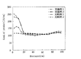
続いて、スパイラル型逆浸透膜エレメントを用いて、NaCl濃度が32,000ppmのNaCl水溶液の分離操作を行った。運転条件として、運転圧力を5.5MPaとし、回収率を10%とした。さらに、エレメント内部に於いて、封止部分から所定距離毎に透過水の電気伝導率を測定した。その結果を、電気伝導率と封止部からの距離との関係を示すグラフを用いて図4に示す。 Subsequently, using a spiral reverse osmosis membrane element, a NaCl aqueous solution having a NaCl concentration of 32,000 ppm was separated. As operating conditions, the operating pressure was 5.5 MPa, and the recovery rate was 10%. Furthermore, the electrical conductivity of the permeated water was measured every predetermined distance from the sealed portion inside the element. The result is shown in FIG. 4 using the graph which shows the relationship between electrical conductivity and the distance from a sealing part.
また、封止部のスキン層側に於ける面の画像データをしきい値230で二値化処理し、処理後の画像データの黒レベルを測定したところ99.5%であった。 Further, the image data of the surface on the skin layer side of the sealing portion was binarized with a threshold value 230, and the black level of the processed image data was measured and found to be 99.5%.
さらに、封止部の不織布層側に於ける面のヘイズ値を、JIS K7136に準拠して測定した。即ち、不織布層側の面にテープ(日東電工製NO.31B)を貼り付けた後にこれを剥がし、剥がしたテープの光透過度をヘイズメーターで測定した。その結果、ヘイズ値は40%であった。
(実施例2)
Furthermore, the haze value of the surface of the sealing portion on the nonwoven fabric layer side was measured according to JIS K7136. That is, after a tape (Nitto Denko NO.31B) was applied to the surface of the nonwoven fabric layer, the tape was peeled off, and the light transmittance of the peeled tape was measured with a haze meter. As a result, the haze value was 40%.
(Example 2)
平均孔径が10.2μmであり、2層構造を持つが互いの層が抄紙段階で融合される為に各層間に抵抗となるバリア層が存在しない不織布を用いて、前記実施例1と同様に行うことにより複合逆浸透膜を得た。次にこの複合逆浸透膜を、粘度25Pa・s、垂れ性35mmのポリウレタン(封止樹脂)を用いて封止しながら中心管に巻いた。これにより、本実施例2に係るスパイラル型逆浸透膜エレメントを作製した。 As in Example 1 above, using a nonwoven fabric having an average pore size of 10.2 μm and having a two-layer structure, but each layer is fused at the papermaking stage and no barrier layer serving as a resistance exists between the layers. The composite reverse osmosis membrane was obtained by performing. Next, this composite reverse osmosis membrane was wound around a central tube while being sealed with polyurethane (sealing resin) having a viscosity of 25 Pa · s and a sag of 35 mm. Thus, a spiral type reverse osmosis membrane element according to Example 2 was produced.
続いて、前記実施例1と同様にしてNaCl水溶液の分離操作を行い、透過水の電気伝導率を測定した。その結果を、電気伝導率と距離との関係を示すグラフを用いて図4に示す。 Subsequently, the NaCl aqueous solution was separated in the same manner as in Example 1, and the electric conductivity of the permeated water was measured. The results are shown in FIG. 4 using a graph showing the relationship between electrical conductivity and distance.
また前記実施例1と同様にして、封止部のスキン層側に於ける面の画像データの黒レベルを測定したところ90.5%であった。 Further, in the same manner as in Example 1, the black level of the image data on the surface of the sealing portion on the skin layer side was measured and found to be 90.5%.
さらに前記実施例1と同様にして、封止部の不織布層側に於ける面のヘイズ値を測定したところ30%であった。
(比較例1)
Further, in the same manner as in Example 1, the haze value of the surface of the sealing portion on the nonwoven fabric layer side was measured and found to be 30%.
(Comparative Example 1)
平均孔径が10.2μmであり、平均孔径と最大孔径の比が5.3である熱融着張り合わせ2層構造の不織布を用い、これに実施例1と同様の方法で複合逆浸透膜を得た。次にこの複合逆浸透膜を粘度22Pa・s、垂れ性35mmのポリウレタン(封止樹脂)を用いて封止しながら中心管に巻いた。これにより、比較例1に係るスパイラル型逆浸透膜エレメントを作製した。 A composite reverse osmosis membrane was obtained in the same manner as in Example 1 using a non-woven fabric having a two-layer structure of heat-sealing and having an average pore size of 10.2 μm and a ratio of the average pore size to the maximum pore size of 5.3. It was. Next, this composite reverse osmosis membrane was wound around a central tube while being sealed with polyurethane (sealing resin) having a viscosity of 22 Pa · s and a sag of 35 mm. Thus, a spiral type reverse osmosis membrane element according to Comparative Example 1 was produced.
続いて、前記実施例1と同様にしてNaCl水溶液の分離操作を行い、透過水の電気伝導率を測定した。その結果を、電気伝導率と距離との関係を示すグラフを用いて図4に示す。 Subsequently, the NaCl aqueous solution was separated in the same manner as in Example 1, and the electric conductivity of the permeated water was measured. The results are shown in FIG. 4 using a graph showing the relationship between electrical conductivity and distance.
また前記実施例1と同様にして、封止部のスキン層側に於ける面の画像データの黒レベルを測定したところ3.0%であった。 In the same manner as in Example 1, the black level of the image data on the surface of the sealing portion on the skin layer side was measured and found to be 3.0%.
さらに前記実施例1と同様にして、封止部の不織布層側に於ける面のヘイズ値を測定したところ5%であった。
(比較例2)
Further, in the same manner as in Example 1, the haze value of the surface of the sealing portion on the nonwoven fabric layer side was measured and found to be 5%.
(Comparative Example 2)
平均孔径が9.4μmであり、平均孔径と最大孔径の比が2.9である1層構造の不織布を用い、これに美施例1と同様の方法で複合逆浸透膜を得た。次にこの複合逆浸透膜を、粘度45Pa・s、垂れ性80mmのポリウレタン(封止樹脂)を用いて封止しながら中心管に巻いた。これにより、比較例2に係るスパイラル型逆浸透膜エレメントを作製した。 A non-woven fabric having a single-layer structure having an average pore diameter of 9.4 μm and a ratio of the average pore diameter to the maximum pore diameter of 2.9 was used, and a composite reverse osmosis membrane was obtained in the same manner as in Beauty Example 1. Next, this composite reverse osmosis membrane was wound around a central tube while being sealed with polyurethane (sealing resin) having a viscosity of 45 Pa · s and a sag of 80 mm. Thereby, a spiral reverse osmosis membrane element according to Comparative Example 2 was produced.
続いて、前記実施例1と同様にしてNaCl水溶液の分離操作を行い、透過水の電気伝導率を測定した。その結果を、電気伝導率と距離との関係を示すグラフを用いて図4に示す。 Subsequently, the NaCl aqueous solution was separated in the same manner as in Example 1, and the electric conductivity of the permeated water was measured. The results are shown in FIG. 4 using a graph showing the relationship between electrical conductivity and distance.
また前記実施例1と同様にして、封止部のスキン層側に於ける面の画像データの黒レベルを測定したところ20%であった。 In the same manner as in Example 1, the black level of the image data on the surface of the sealing portion on the skin layer side was measured and found to be 20%.
さらに前記実施例1と同様にして、封止部の不織布層側に於ける面のヘイズ値を測定したところ35%であった。 Further, in the same manner as in Example 1, the haze value of the surface of the sealing portion on the nonwoven fabric layer side was measured and found to be 35%.
(結果)
図4に示すグラフから明らかな様に、実施例1及び2に係るスパイラル型逆浸透膜エレメントの場合、封止部分近傍(封止部分からの距離が0〜5cmの範囲内)の透過水の電気伝導率は、内部(封止部分からの距離が5〜90cmの範囲内)の透過水の電気伝導率の2倍以内であり、良好な塩阻止率を示していることが分かる。その一方、比較例1及び2に係るスパイラル型逆浸透膜エレメントの場合、封止部分近傍の透過水の電気伝導率は、内部の透過水の電気伝導率と比較して2倍を超えており、塩阻止率が高く分離性能が劣っていることが分かる。
(result)
As apparent from the graph shown in FIG. 4, in the case of the spiral reverse osmosis membrane elements according to Examples 1 and 2, the permeated water near the sealing portion (within a distance of 0 to 5 cm from the sealing portion). It can be seen that the electric conductivity is within twice the electric conductivity of the permeated water inside (within a distance of 5 to 90 cm from the sealing portion), indicating a good salt rejection. On the other hand, in the case of the spiral type reverse osmosis membrane element according to Comparative Examples 1 and 2, the electric conductivity of the permeated water in the vicinity of the sealing portion exceeds twice the electric conductivity of the inner permeated water. It can be seen that the salt rejection is high and the separation performance is poor.
1 分離膜
2 供給側流路材
3 透過側流路材
4 接着剤
5 中心管
6 接着剤
11 両端封止部
12 外周側封止部
R 円筒状巻回体
U 分離膜ユニット
DESCRIPTION OF
Claims (9)
前記透過側流路材を介して対向する分離膜は、不織布層上に多孔性支持体及びスキン層が順次積層された構造を有し、
前記分離膜の縁部には封止樹脂により封止された封止部が設けられており、
前記封止樹脂は、多孔性支持体に於いてスキン層まで含浸されており、
前記不織布層の外側面、及び不織布層が複数層からなる場合には各層間には、前記封止樹脂の含浸を阻害するバリア部が設けられておらず、
かつ、前記不織布層の前記多孔性支持体と接する側には、当該多孔性支持体を構成するポリマーが3〜6g/m 2 の含浸量で含浸されていることを特徴とするスパイラル型逆浸透膜エレメント。 A separation membrane, a supply-side flow path material, and a permeate-side flow path material are provided with a cylindrical wound body spirally wound around a perforated central tube in a laminated state, and a supply-side fluid and a permeation-side fluid A spiral type reverse osmosis membrane element provided with a sealing portion for preventing mixing,
The separation membrane facing through the permeate channel material has a structure in which a porous support and a skin layer are sequentially laminated on a nonwoven fabric layer,
A sealing portion sealed with a sealing resin is provided at the edge of the separation membrane,
The sealing resin is impregnated up to the skin layer in the porous support ,
When the outer surface of the non-woven fabric layer and the non-woven fabric layer are composed of a plurality of layers, each layer is not provided with a barrier portion that impedes impregnation of the sealing resin,
A spiral reverse osmosis is characterized in that a polymer constituting the porous support is impregnated in an amount of 3 to 6 g / m 2 on the side of the nonwoven fabric layer in contact with the porous support. Membrane element.
前記不織布層の平均孔径は8〜12μmであり、かつ平均孔径と最大孔径の比(最大孔径/平均孔径)は1〜4であることを特徴とするスパイラル型逆浸透膜エレメント。 The spiral reverse osmosis membrane element according to claim 1,
The spiral-type reverse osmosis membrane element characterized in that the nonwoven fabric layer has an average pore diameter of 8 to 12 μm and a ratio of the average pore diameter to the maximum pore diameter (maximum pore diameter / average pore diameter) of 1 to 4.
前記多孔性支持体の厚さは30〜60μmであることを特徴とするスパイラル型逆浸透膜エレメント。 The spiral reverse osmosis membrane element according to claim 1 or 2 ,
The spiral reverse osmosis membrane element, wherein the porous support has a thickness of 30 to 60 µm.
前記分離膜は、前記封止部のスキン層側に於ける面の画像データをしきい値230で二値化処理した場合に、処理後の画像データの黒レベルが60%以上となるまで前記ポリマーを前記多孔性支持体に含浸したものであることを特徴とするスパイラル型逆浸透膜エレメント。 The spiral reverse osmosis membrane element according to any one of claims 1 to 3 ,
When the image data of the surface on the skin layer side of the sealing portion is binarized with a threshold value 230, the separation film is processed until the black level of the processed image data reaches 60% or more. A spiral reverse osmosis membrane element, wherein the porous support is impregnated with a polymer.
前記分離膜は、前記封止部の不織布層側に於ける面のヘイズ値が20%以上になるまで前記ポリマーを前記多孔性支持体に含浸したものであることを特徴とするスパイラル型逆浸透膜エレメント。 The spiral reverse osmosis membrane element according to any one of claims 1 to 4 ,
The separation membrane is a spiral reverse osmosis characterized in that the porous support is impregnated with the polymer until the haze value of the surface on the nonwoven fabric layer side of the sealing portion is 20% or more. Membrane element.
前記不織布層上に前記多孔性支持体を構成するポリマーを塗布し、かつ、当該ポリマーを含浸量が3〜6g/m2の範囲内になる様に含浸させた後、乾燥させて多孔性支持体を形成する工程と、
前記多孔性支持体上にスキン層を製膜して分離膜を形成する工程と、
前記分離膜と供給側流路材と透過側流路材とを積層状態で有孔の中心管の周囲にスパイラル状に巻回して円筒状巻回体を形成する工程と、
前記供給側流体と透過側流体の混合を防ぐため、透過側流路材を介して対向する分離膜の縁部に、多孔性支持体側から封止樹脂を塗布し、かつ封止樹脂をスキン層まで含浸させて封止する工程とを有し、
前記不織布層として、その外側面、及び不織布層が複数層からなる場合には各層間に、前記封止樹脂の含浸を阻害するバリア部が設けられていないものを使用することを特徴とするスパイラル型逆浸透膜エレメントの製造方法。 A separation membrane in which a porous support and a skin layer are sequentially laminated on a nonwoven fabric layer , a supply-side channel material and a permeation-side channel material were spirally wound around a perforated central tube in a laminated state. A spiral reverse osmosis membrane element manufacturing method provided with a cylindrical wound body and provided with a sealing portion for preventing mixing of a supply side fluid and a permeate side fluid,
The porous support is coated with a polymer constituting the porous support on the nonwoven fabric layer, impregnated with the polymer so that the impregnation amount is in the range of 3 to 6 g / m2, and then dried. Forming a step;
Forming a skin layer on the porous support to form a separation membrane;
A step of forming a cylindrical wound body by spirally winding the separation membrane, the supply-side flow path material, and the permeation-side flow path material around a perforated central tube;
In order to prevent mixing of the supply side fluid and the permeation side fluid, a sealing resin is applied from the porous support side to the edge of the separation membrane facing through the permeation side flow path member, and the sealing resin is applied to the skin layer. until impregnated possess the step of sealing,
Spiral characterized in that the non-woven fabric layer is a spiral layer characterized in that, when the non-woven fabric layer is composed of a plurality of layers, the non-woven fabric layer is not provided with a barrier portion that impedes impregnation of the sealing resin. Type reverse osmosis membrane element manufacturing method.
前記分離膜の形成工程の前に、2以上の反応性のアミノ基を有する多官能性アミノ化合物を含む溶液を調製する工程と、
2以上の反応性の酸ハライド基を有する多官能性酸ハライド化合物を含む溶液を調製する工程とを行い、
前記分離膜の形成工程は、前記多官能性アミノ化合物と多官能性酸ハライド化合物とを界面重合させて前記スキン層としてのポリアミド層を形成する工程であることを特徴とするスパイラル型逆浸透膜エレメントの製造方法。 It is a manufacturing method of the spiral type reverse osmosis membrane element according to claim 6 ,
Preparing a solution containing a polyfunctional amino compound having two or more reactive amino groups before the separation membrane forming step;
And a step of preparing a solution containing a polyfunctional acid halide compound having two or more reactive acid halide groups,
The step of forming the separation membrane is a step of forming a polyamide layer as the skin layer by interfacially polymerizing the polyfunctional amino compound and a polyfunctional acid halide compound. Element manufacturing method.
前記封止樹脂として、含浸の際の粘度が10〜40Pa・sの範囲内のものを使用することを特徴とするスパイラル型逆浸透膜エレメントの製造方法。 It is a manufacturing method of the spiral type reverse osmosis membrane element according to claim 6 or 7 ,
A method for producing a spiral-type reverse osmosis membrane element, wherein the sealing resin has a viscosity during impregnation in the range of 10 to 40 Pa · s.
前記封止樹脂の塗布量は0.2〜1g/cmThe application amount of the sealing resin is 0.2-1 g / cm. 22 の範囲内であることを特徴とするスパイラル型逆浸透膜エレメントの製造方法。The manufacturing method of the spiral type reverse osmosis membrane element characterized by being in the range.
Priority Applications (6)
| Application Number | Priority Date | Filing Date | Title |
|---|---|---|---|
| JP2004255779A JP4484635B2 (en) | 2004-09-02 | 2004-09-02 | Spiral type reverse osmosis membrane element and manufacturing method thereof |
| KR1020050081271A KR100809178B1 (en) | 2004-09-02 | 2005-09-01 | Spiral reverse osmosis membrane element, method of manufacturing the same, and its use method |
| US11/216,051 US8608964B2 (en) | 2004-09-02 | 2005-09-01 | Spiral reverse osmosis membrane element, method of manufacturing the same, and its use method |
| ES05019120.4T ES2446920T3 (en) | 2004-09-02 | 2005-09-02 | Element of spiral osmosis membrane and its manufacturing process |
| EP05019120.4A EP1637214B1 (en) | 2004-09-02 | 2005-09-02 | Spiral reverse osmosis membrane element and method of manufacturing the same |
| US12/173,694 US8591684B2 (en) | 2004-09-02 | 2008-07-15 | Spiral reverse osmosis membrane element, method of manufacturing the same, and its use method |
Applications Claiming Priority (1)
| Application Number | Priority Date | Filing Date | Title |
|---|---|---|---|
| JP2004255779A JP4484635B2 (en) | 2004-09-02 | 2004-09-02 | Spiral type reverse osmosis membrane element and manufacturing method thereof |
Publications (2)
| Publication Number | Publication Date |
|---|---|
| JP2006068644A JP2006068644A (en) | 2006-03-16 |
| JP4484635B2 true JP4484635B2 (en) | 2010-06-16 |
Family
ID=35432348
Family Applications (1)
| Application Number | Title | Priority Date | Filing Date |
|---|---|---|---|
| JP2004255779A Expired - Lifetime JP4484635B2 (en) | 2004-09-02 | 2004-09-02 | Spiral type reverse osmosis membrane element and manufacturing method thereof |
Country Status (5)
| Country | Link |
|---|---|
| US (2) | US8608964B2 (en) |
| EP (1) | EP1637214B1 (en) |
| JP (1) | JP4484635B2 (en) |
| KR (1) | KR100809178B1 (en) |
| ES (1) | ES2446920T3 (en) |
Families Citing this family (60)
| Publication number | Priority date | Publication date | Assignee | Title |
|---|---|---|---|---|
| WO2009151709A2 (en) * | 2008-03-20 | 2009-12-17 | Yale University | Spiral wound membrane module for forward osmotic use |
| US8177978B2 (en) | 2008-04-15 | 2012-05-15 | Nanoh20, Inc. | Reverse osmosis membranes |
| EP2425889B1 (en) * | 2009-04-30 | 2014-09-03 | Asahi Kasei Fibers Corporation | Composite membrane substrate and composite membrane using same |
| EA026762B1 (en) * | 2009-08-24 | 2017-05-31 | Оасис Уотер, Инк. | Forward osmosis membrane |
| WO2011069050A1 (en) | 2009-12-03 | 2011-06-09 | Yale University | High flux thin-film composite forward osmosis and pressure-retarded osmosis membranes |
| WO2011119280A1 (en) | 2010-03-24 | 2011-09-29 | Dow Global Technologies Llc | Spiral wound filtration module |
| JP5950914B2 (en) * | 2010-09-06 | 2016-07-13 | エルジー・ケム・リミテッド | Separator, method for manufacturing the same, and electrochemical device including the same |
| KR20130101533A (en) | 2010-10-04 | 2013-09-13 | 오아시스 워터, 인크. | Thin film composite heat exchangers |
| EP2576028B1 (en) * | 2010-10-26 | 2014-04-23 | Dow Global Technologies LLC | Spiral wound module including membrane sheet with regions having different permeabilities |
| CN102553445A (en) | 2010-12-30 | 2012-07-11 | 通用电气公司 | Separator assembly method and apparatus |
| US8940169B2 (en) * | 2011-03-10 | 2015-01-27 | General Electric Company | Spiral wound membrane element and treatment of SAGD produced water or other high temperature alkaline fluids |
| US8882972B2 (en) | 2011-07-19 | 2014-11-11 | Ecolab Usa Inc | Support of ion exchange membranes |
| US9522363B2 (en) | 2011-10-19 | 2016-12-20 | General Electric Company | Material efficiency and fabrication of membrane elements |
| US9675937B2 (en) | 2011-10-19 | 2017-06-13 | General Electric Company | Spiral wound membrane permeate carrier with thin border |
| US20150182918A1 (en) | 2012-03-02 | 2015-07-02 | Dow Global Technologies Llc | Multi-pass hyperfiltration system |
| JP6012418B2 (en) * | 2012-11-12 | 2016-10-25 | 富士フイルム株式会社 | Spiral type separation membrane module, method for manufacturing spiral type separation membrane module and support |
| WO2014176067A1 (en) | 2013-04-26 | 2014-10-30 | Dow Global Technologies Llc | Assembly including serially connected spiral wound modules with permeate flow controller |
| JP2016026859A (en) * | 2013-08-19 | 2016-02-18 | 富士フイルム株式会社 | Acid gas separation spiral module |
| JP6305729B2 (en) | 2013-11-05 | 2018-04-04 | 日東電工株式会社 | Composite semipermeable membrane |
| WO2015105632A1 (en) | 2014-01-07 | 2015-07-16 | Dow Global Technologies Llc | Separation of hydrocarbons from aqueous mixture using fouling resistant reverse osmosis membrane |
| WO2015105630A1 (en) | 2014-01-07 | 2015-07-16 | Dow Global Technologies Llc | Treatment of aqueous mixtures containing anionic surfactants using fouling resistant reverse osmosis membrane |
| JP6521422B2 (en) * | 2014-02-07 | 2019-05-29 | 日東電工株式会社 | Spiral type separation membrane element |
| US10258928B2 (en) | 2014-03-31 | 2019-04-16 | Dow Global Technologies Llc | Spiral wound membrane module adapted for high recovery |
| JP6475326B2 (en) | 2014-09-24 | 2019-02-27 | ダウ グローバル テクノロジーズ エルエルシー | A spiral filtration assembly including an integral bioreactor |
| WO2016054380A1 (en) | 2014-10-01 | 2016-04-07 | H.B. Fuller Company | Method of making spiral wound filtration modules with a curable adhesive composition and modules made thereby |
| BR112017016351A2 (en) | 2015-02-11 | 2018-03-27 | Dow Global Technologies Llc | submerged hyperfiltration system |
| US10010833B2 (en) | 2015-02-18 | 2018-07-03 | Lg Nanoh2O, Inc. | Spiral wound membrane module with reinforced fold line |
| EP3283197B1 (en) | 2015-04-16 | 2019-06-19 | Dow Global Technologies LLC | Filtration assembly including spiral wound bioreactors and membrane modules positioned in separate pressure vessels |
| EP3283198B1 (en) | 2015-04-16 | 2019-08-14 | Dow Global Technologies LLC | Filtration assembly including spiral wound bioreactors and hyperfiltration membrane modules |
| WO2017000653A1 (en) * | 2015-06-30 | 2017-01-05 | 佛山市美的清湖净水设备有限公司 | Reverse osmosis membrane assembly and manufacturing method therefor |
| WO2017000652A1 (en) * | 2015-06-30 | 2017-01-05 | 佛山市美的清湖净水设备有限公司 | Reverse osmosis membrane assembly and manufacturing method therefor |
| CN107847867B (en) | 2015-07-01 | 2021-06-25 | 3M创新有限公司 | Composite membranes with improved properties and/or durability and methods of using the same |
| CN107921370B (en) | 2015-07-01 | 2022-03-29 | 3M创新有限公司 | Polymeric ionomer separation membranes and methods of use thereof |
| WO2017004492A1 (en) | 2015-07-01 | 2017-01-05 | 3M Innovative Properties Company | Pvp- and/or pvl-containing composite membranes and methods of use |
| CN106390751B (en) * | 2015-07-27 | 2020-11-06 | 深圳市诚德来实业有限公司 | RO (reverse osmosis) membrane eddy element and manufacturing method thereof |
| EP3328524B8 (en) | 2015-07-29 | 2020-03-04 | DDP Specialty Electronic Materials US, Inc. | Filter assembly including spiral wound membrane module and brine seal |
| US9861940B2 (en) | 2015-08-31 | 2018-01-09 | Lg Baboh2O, Inc. | Additives for salt rejection enhancement of a membrane |
| US10252473B2 (en) | 2015-08-31 | 2019-04-09 | Lg Nanoh2O, Inc. | Compression bar apparatus |
| JP6747926B2 (en) | 2015-09-30 | 2020-08-26 | 日東電工株式会社 | Method for manufacturing spiral type separation membrane element |
| KR102096766B1 (en) | 2015-09-30 | 2020-04-03 | 다우 글로벌 테크놀로지스 엘엘씨 | Filter assembly including spiral winding module, brine seal and end cap |
| EP3368482A4 (en) | 2015-10-30 | 2019-07-03 | Dow Global Technologies, LLC | Membrane treatment of ammonia-containing waste water |
| US9737859B2 (en) | 2016-01-11 | 2017-08-22 | Lg Nanoh2O, Inc. | Process for improved water flux through a TFC membrane |
| US10155203B2 (en) | 2016-03-03 | 2018-12-18 | Lg Nanoh2O, Inc. | Methods of enhancing water flux of a TFC membrane using oxidizing and reducing agents |
| CN109641177A (en) | 2016-08-31 | 2019-04-16 | 陶氏环球技术有限责任公司 | Spiral wound modules sub-assembly comprising integrating penetrant monitoring |
| JP7121036B2 (en) | 2017-04-05 | 2022-08-17 | ダウ グローバル テクノロジーズ エルエルシー | Spiral wound module assembly with integrated pressure monitoring |
| KR102585046B1 (en) | 2017-07-27 | 2023-10-10 | 디디피 스페셜티 일렉트로닉 머티리얼즈 유에스, 엘엘씨 | Spiral-wound membrane module with integrated differential pressure monitoring |
| NZ735748A (en) | 2017-09-22 | 2018-07-27 | Dehlsen Associates Of The Pacific Ltd | Reverse osmosis water production apparatus |
| US11660572B2 (en) | 2017-09-22 | 2023-05-30 | Dehlsen Associates of the Pacific, Limited | Wind and wave desalination vessel |
| CN111989151B (en) | 2018-01-15 | 2023-10-03 | Ddp特种电子材料美国有限责任公司 | Spiral-wound assembly with integrated flow restrictor and sensor |
| JP6522185B2 (en) * | 2018-03-07 | 2019-05-29 | 日東電工株式会社 | Composite semipermeable membrane |
| CN108786483B (en) * | 2018-06-05 | 2021-01-22 | 四川大学 | Method for preparing composite film by microporous interface convection polymerization and composite film prepared therefrom |
| CN109200828A (en) * | 2018-10-19 | 2019-01-15 | 时代沃顿科技有限公司 | A kind of welded type rolled film method for coiling |
| JP7302973B2 (en) * | 2019-01-18 | 2023-07-04 | 日東電工株式会社 | SPIRAL MEMBRANE ELEMENT AND MANUFACTURING METHOD THEREOF |
| US12246289B2 (en) | 2019-01-29 | 2025-03-11 | Ddp Specialty Electronic Materials Us, Llc | Measurement of pressure differences within a vessel of spiral wound membrane modules |
| CN116096481A (en) | 2020-07-30 | 2023-05-09 | Ddp特种电子材料美国有限责任公司 | Spiral wound membrane module with sensor and emitter |
| US11535531B2 (en) | 2020-08-05 | 2022-12-27 | NL Chemical Technology, Inc. | Reduced lateral leakage in reverse osmosis devices |
| KR102924357B1 (en) * | 2020-10-23 | 2026-02-05 | 주식회사 엘지화학 | Quantitative analysis and visualization method of oxidation degree of reverse osmosis membrane |
| WO2023033876A1 (en) | 2021-09-03 | 2023-03-09 | Ddp Specialty Electronic Materials Us, Llc | Spiral wound membrane element |
| JP2023143687A (en) | 2022-03-24 | 2023-10-06 | 日東電工株式会社 | Composite semipermeable membrane and spiral membrane element |
| WO2025129489A1 (en) | 2023-12-20 | 2025-06-26 | Ddp Specialty Electronic Materials Us, Llc | Lithium extraction method |
Family Cites Families (31)
| Publication number | Priority date | Publication date | Assignee | Title |
|---|---|---|---|---|
| JPS501707B1 (en) * | 1969-12-20 | 1975-01-21 | ||
| US4033878A (en) | 1975-05-12 | 1977-07-05 | Universal Oil Products Company | Spiral wound membrane module for direct osmosis separations |
| US4021351A (en) | 1975-10-30 | 1977-05-03 | Desalination Systems, Inc. | Membrane cartridge with improved central collection tube |
| GB1546529A (en) * | 1976-07-13 | 1979-05-23 | Toray Industries | Production of a liquid separation module utilizing semipermeable membranes |
| JPS5939460B2 (en) * | 1976-12-10 | 1984-09-22 | 日石三菱株式会社 | Manufacturing method of porous membrane |
| JPS56136606A (en) | 1980-03-28 | 1981-10-26 | Nitto Electric Ind Co Ltd | Winding method for spiral type membrane element |
| DE3220613A1 (en) | 1982-06-01 | 1983-12-01 | GFT Ingenieurbüro für Industrieanlagenbau, 6650 Homburg | MEMBRANE MODULE AND ITS USE FOR SEPARATING LIQUIDS BY PERVAPORATION PROCESS |
| JPS5973008A (en) | 1982-10-19 | 1984-04-25 | Nitto Electric Ind Co Ltd | Preparation of fluid separation apparatus |
| US4464494A (en) * | 1983-05-13 | 1984-08-07 | Exxon Research & Engineering Co. | Adhesive system for production of spiral wound membrane elements for use in organic fluid mixture separations |
| US4582726A (en) * | 1983-12-14 | 1986-04-15 | Exxon Research And Engineering Co. | Adhesive system for use in preparing membrane elements for extraction solvent recovery processes |
| US4834881A (en) | 1987-08-19 | 1989-05-30 | Kurita Water Industries Ltd. | Spiral wound type membrane module |
| US4802982A (en) | 1987-10-01 | 1989-02-07 | Desalination Systems, Inc. | Spiral-wound membrane with improved permeate carrier |
| US4872984A (en) * | 1988-09-28 | 1989-10-10 | Hydranautics Corporation | Interfacially synthesized reverse osmosis membrane containing an amine salt and processes for preparing the same |
| US5266195A (en) * | 1992-08-10 | 1993-11-30 | Desalination Systems, Inc. | Spiral wound separation device and method of making same |
| JPH0671147A (en) * | 1992-08-25 | 1994-03-15 | Nitto Denko Corp | Dual film |
| JPH0771623A (en) * | 1993-08-17 | 1995-03-17 | Nissan Motor Co Ltd | Fixed structure for boots for console finishers |
| JPH07204471A (en) * | 1994-01-27 | 1995-08-08 | Toray Ind Inc | Spiral type fluid separation element and manufacturing method thereof |
| JP3489922B2 (en) * | 1994-12-22 | 2004-01-26 | 日東電工株式会社 | Method for producing highly permeable composite reverse osmosis membrane |
| JPH10137558A (en) * | 1996-11-11 | 1998-05-26 | Nitto Denko Corp | Spiral type separation membrane element and method for producing the same |
| JP3608353B2 (en) | 1997-09-30 | 2005-01-12 | 日立プラント建設株式会社 | Membrane module and water treatment apparatus using the same |
| WO2000044481A1 (en) | 1999-01-27 | 2000-08-03 | Koch Membrane Systems, Inc. | Method for sealing axial seam of spiral wound filtration modules |
| JP2000342933A (en) * | 1999-06-08 | 2000-12-12 | Toray Ind Inc | Fluid separation membrane element and method of manufacturing the same |
| JP2001198442A (en) * | 2000-01-18 | 2001-07-24 | Toray Ind Inc | Fluid separation element, method of manufacturing the same, and fluid separation membrane module |
| JP2001252540A (en) * | 2000-03-10 | 2001-09-18 | Toray Ind Inc | Reverse osmosis composite membrane |
| JP4289757B2 (en) * | 2000-03-23 | 2009-07-01 | 日東電工株式会社 | Method for producing composite reverse osmosis membrane |
| JP4786122B2 (en) * | 2000-12-22 | 2011-10-05 | ジーイー・オズモニクス・インコーポレイテッド | Cross flow filter media and cartridge |
| US20030034293A1 (en) * | 2001-08-16 | 2003-02-20 | Pti Advanced Filtration, Inc. | Method of treating filtration media to prevent lateral flow, blistering and de-lamination |
| JP2003088730A (en) * | 2001-09-20 | 2003-03-25 | Nitto Denko Corp | Reverse osmosis membrane element processing method and reverse osmosis membrane module |
| DK1519782T3 (en) | 2002-06-21 | 2009-11-30 | Ge Osmonics Inc | Bladder protection for spirally wound elements |
| US7051883B2 (en) * | 2003-07-07 | 2006-05-30 | Reemay, Inc. | Wetlaid-spunbond laminate membrane support |
| JP2005199141A (en) | 2004-01-14 | 2005-07-28 | Nitto Denko Corp | Spiral type membrane element and manufacturing method thereof |
-
2004
- 2004-09-02 JP JP2004255779A patent/JP4484635B2/en not_active Expired - Lifetime
-
2005
- 2005-09-01 KR KR1020050081271A patent/KR100809178B1/en not_active Expired - Lifetime
- 2005-09-01 US US11/216,051 patent/US8608964B2/en active Active
- 2005-09-02 ES ES05019120.4T patent/ES2446920T3/en not_active Expired - Lifetime
- 2005-09-02 EP EP05019120.4A patent/EP1637214B1/en not_active Expired - Lifetime
-
2008
- 2008-07-15 US US12/173,694 patent/US8591684B2/en not_active Expired - Fee Related
Also Published As
| Publication number | Publication date |
|---|---|
| ES2446920T3 (en) | 2014-03-10 |
| JP2006068644A (en) | 2006-03-16 |
| EP1637214B1 (en) | 2013-12-25 |
| US8591684B2 (en) | 2013-11-26 |
| US20080295951A1 (en) | 2008-12-04 |
| EP1637214A1 (en) | 2006-03-22 |
| US20060043013A1 (en) | 2006-03-02 |
| KR20060050930A (en) | 2006-05-19 |
| US8608964B2 (en) | 2013-12-17 |
| KR100809178B1 (en) | 2008-02-29 |
Similar Documents
| Publication | Publication Date | Title |
|---|---|---|
| JP4484635B2 (en) | Spiral type reverse osmosis membrane element and manufacturing method thereof | |
| CN102574071B (en) | Forward osmosis membranes | |
| US10682615B2 (en) | Composite semi-permeable membrane | |
| JP6522185B2 (en) | Composite semipermeable membrane | |
| JP6521422B2 (en) | Spiral type separation membrane element | |
| JP6747926B2 (en) | Method for manufacturing spiral type separation membrane element | |
| WO2016052427A1 (en) | Composite semipermeable membrane and method for producing same, and spiral separation membrane element | |
| JPH09313905A (en) | Polysulfone porous separation membrane | |
| JPWO2017057378A1 (en) | Composite semipermeable membrane | |
| AU2015227384A1 (en) | Forward osmosis membranes |
Legal Events
| Date | Code | Title | Description |
|---|---|---|---|
| A621 | Written request for application examination |
Free format text: JAPANESE INTERMEDIATE CODE: A621 Effective date: 20061106 |
|
| A977 | Report on retrieval |
Free format text: JAPANESE INTERMEDIATE CODE: A971007 Effective date: 20081023 |
|
| A131 | Notification of reasons for refusal |
Free format text: JAPANESE INTERMEDIATE CODE: A131 Effective date: 20081107 |
|
| A521 | Request for written amendment filed |
Free format text: JAPANESE INTERMEDIATE CODE: A523 Effective date: 20090106 |
|
| RD03 | Notification of appointment of power of attorney |
Free format text: JAPANESE INTERMEDIATE CODE: A7423 Effective date: 20090106 |
|
| TRDD | Decision of grant or rejection written | ||
| A01 | Written decision to grant a patent or to grant a registration (utility model) |
Free format text: JAPANESE INTERMEDIATE CODE: A01 Effective date: 20100316 |
|
| A01 | Written decision to grant a patent or to grant a registration (utility model) |
Free format text: JAPANESE INTERMEDIATE CODE: A01 |
|
| A61 | First payment of annual fees (during grant procedure) |
Free format text: JAPANESE INTERMEDIATE CODE: A61 Effective date: 20100323 |
|
| R150 | Certificate of patent or registration of utility model |
Ref document number: 4484635 Country of ref document: JP Free format text: JAPANESE INTERMEDIATE CODE: R150 Free format text: JAPANESE INTERMEDIATE CODE: R150 |
|
| FPAY | Renewal fee payment (event date is renewal date of database) |
Free format text: PAYMENT UNTIL: 20130402 Year of fee payment: 3 |
|
| FPAY | Renewal fee payment (event date is renewal date of database) |
Free format text: PAYMENT UNTIL: 20160402 Year of fee payment: 6 |
|
| R250 | Receipt of annual fees |
Free format text: JAPANESE INTERMEDIATE CODE: R250 |
|
| R250 | Receipt of annual fees |
Free format text: JAPANESE INTERMEDIATE CODE: R250 |
|
| R250 | Receipt of annual fees |
Free format text: JAPANESE INTERMEDIATE CODE: R250 |
|
| R250 | Receipt of annual fees |
Free format text: JAPANESE INTERMEDIATE CODE: R250 |
|
| R250 | Receipt of annual fees |
Free format text: JAPANESE INTERMEDIATE CODE: R250 |
|
| R250 | Receipt of annual fees |
Free format text: JAPANESE INTERMEDIATE CODE: R250 |
|
| R250 | Receipt of annual fees |
Free format text: JAPANESE INTERMEDIATE CODE: R250 |
|
| R250 | Receipt of annual fees |
Free format text: JAPANESE INTERMEDIATE CODE: R250 |
|
| R250 | Receipt of annual fees |
Free format text: JAPANESE INTERMEDIATE CODE: R250 |
|
| R250 | Receipt of annual fees |
Free format text: JAPANESE INTERMEDIATE CODE: R250 |
|
| EXPY | Cancellation because of completion of term |