JP4483169B2 - Device control system - Google Patents
Device control system Download PDFInfo
- Publication number
- JP4483169B2 JP4483169B2 JP2002344282A JP2002344282A JP4483169B2 JP 4483169 B2 JP4483169 B2 JP 4483169B2 JP 2002344282 A JP2002344282 A JP 2002344282A JP 2002344282 A JP2002344282 A JP 2002344282A JP 4483169 B2 JP4483169 B2 JP 4483169B2
- Authority
- JP
- Japan
- Prior art keywords
- person
- data
- computer
- information
- notation
- Prior art date
- Legal status (The legal status is an assumption and is not a legal conclusion. Google has not performed a legal analysis and makes no representation as to the accuracy of the status listed.)
- Expired - Fee Related
Links
Images


Description
【0001】
【発明の属する技術分野】
本発明は、ネットワーク上に存在する複数のデバイスの中から、所望の人物に関係するデバイスを検索するための技術に関するものである。
【0002】
【従来の技術】
従来、例えば、Microsoft社製のOSであるWindow95やWindowsNTなどにおいては、コンピュータ名を検索条件として、ネットワーク上に存在する特定のコンピュータを検索する機能や、ファイル名やフォルダ名を検索条件として、ネットワーク上に存在する特定のコンピュータに格納されたファイルやフォルダを検索する機能を有していた。また、同じくMicrosoft社製のOSであるWindow98では、人の名前の検索条件として、特定の人のメールアドレスを検索する機能を有していた。
【0003】
【発明が解決しようとする課題】
一般に、ネットワークには、複数のコンピュータが接続されており、さらに、それらコンピュータを介してまたは直接的に、プリンタやスキャナやファクシミリなど種々のデバイスが接続されている。これらのデバイスは、或る人に所有されていたり、使用されていたり、あるいは、或る人の近くに置かれていたり、また、或る人の居るフロアやセクションと同じフロアやセクションに設置されていたりしていて、人との間で何らかの関係を有している。
【0004】
従って、例えば、ネットワークを利用している或る人に文書や画像などを届けたい場合に、人を検索条件として、ネットワーク上に存在するデバイスの中から、その人に関係しているデバイスを検索することができれば、それにより得られたデバイスに向かって文書や画像のデータを伝送するだけで、その人に文書や画像を届けることができるため、ユーザにとって非常に便利である。
【0005】
しかしながら、従来においては、上記したように、ネットワーク上に存在する特定のコンピュータを検索したり、人の名前を検索条件としてメールアドレスを検索したりする機能を持つものしかなかった。
【0006】
そこで、本発明の目的は、上記した従来技術の問題点を解決し、ネットワーク上に存在する複数のデバイスの中から、所望の人物に関係するデバイスを検索することが可能なデバイス検索装置及びその方法並びに記録媒体を提供することにある。
【0007】
【課題を解決するための手段およびその作用・効果】
上記した目的の少なくとも一部を達成するために、本発明の第1のデバイス検索装置は、ネットワーク上に存在する複数のデバイスの中から、所望の人物に関係するデバイスを検索するためのデバイス検索装置であって、
画面を有する表示手段と、
外部から指示を入力するための入力手段と、
制御手段と、
を備え、
前記制御手段は、外部から前記入力手段を介して、前記所望の人物の人物表記が特定人物表記として入力された場合に、前記ネットワーク上または前記デバイス検索装置内に存在するデータベースにアクセスし、該データベースに格納された、複数の人物表記と前記ネットワーク上に存在する前記デバイスのデバイス表記との関係付けを表す関係付け情報から、入力された前記特定人物表記に関係付けられたデバイス表記を取得して、取得した前記デバイス表記及び該デバイス表記の表すデバイスに対応するデバイスシンボルのうちの少なくとも一方を前記表示手段の画面上に表示させることを要旨とする。
【0008】
また、本発明の第1のデバイス検索方法は、ネットワーク上に存在する複数のデバイスの中から、所望の人物に関係するデバイスを検索し、その検索結果を表示手段の画面上に表示するデバイス検索方法であって、
(a)前記所望の人物の人物表記を指示する工程と、
(b)予め用意された、複数の人物表記と前記ネットワーク上に存在する前記デバイスのデバイス表記との関係付けを表す関係付け情報から、指示された前記人物表記に関係付けられたデバイス表記を取得する工程と、
(c)取得した前記デバイス表記及び該デバイス表記の表すデバイスに対応するデバイスシンボルのうちの少なくとも一方を前記表示手段の画面上に表示する工程と、
を備えることを要旨とする。
【0009】
このように、第1のデバイス検索装置または方法によれば、所望の人物の人物表記を検索条件として指示することによって、その人物表記に関係付けられたデバイス表記またはそれに対応するデバイスシンボルが画面上に表示されるので、ユーザはその人物に関係するデバイスをネットワーク上から容易に検索することができる。従って、例えば、ユーザが、その人物に対し所望の文書や画像などを伝送したい場合でも、その人物に関係するデバイスを直ちに把握して、そのデバイスに向かって文書や画像のデータの伝送を開始させることが可能となる。
【0010】
なお、本明細書において、AとBとの関係付けには、AとBとが直接的に関係する場合の他、AとBとが間接的に関係する場合(例えば、AとCとが関係し、且つCとBとが関係し、AとBとはCを媒介として関係する場合など)なども含まれる。
【0011】
また、本明細書中において、デバイスには、プリンタやデジタルカメラやスキャナやファクシミリなどの物理的なデバイスのみならず、物理的デバイスの有する機能の一部や、ソフトウェアによって物理的デバイスと同等の機能を有するもの(例えば、電子メールや画像処理)も含まれる。
【0012】
また、本明細書中において、人物表記あるいはデバイス表記には、その人物やデバイスの名前の他、識別番号や符号など、その人物やデバイスを識別できる表記が全て含まれる。また、デバイスシンボルには、デバイスに対応した図柄を表すアイコンなどの他、それに対応した文字や、図形や、記号や、符号や、色彩など、画面上に表示可能であり、ユーザが識別可能であるものが含まれる。なお、このことは、後述する人物シンボルやデータシンボルについても同様である。例えば、人物シンボルの場合、人物に対応した図柄としては、その人物の写真やイラストなどを用いることができる。
【0013】
本発明の第2のデバイス検索装置は、ネットワーク上に存在する複数のデバイスの中から、所望の人物に関係するデバイスを検索するためのデバイス検索装置であって、
画面を有する表示手段と、
外部からの指示を入力するための入力手段と、
制御手段と、
を備え、
前記制御手段は、人物に対応した人物シンボルを前記表示手段の画面上に表示させると共に、
外部から前記入力手段を介して、前記画面上に表示された人物シンボルの中から、前記所望の人物に対応した人物シンボルを選択する旨の指示が入力された場合に、選択された前記人物シンボルに対応した人物の人物表記を特定人物表記として、前記ネットワーク上または前記デバイス検索装置内に存在するデータベースにアクセスし、該データベースに格納された、複数の人物表記と前記ネットワーク上に存在する前記デバイスのデバイス表記との関係付けを表す関係付け情報から、前記特定人物表記に関係付けられたデバイス表記を取得して、取得した前記デバイス表記及び該デバイス表記の表すデバイスに対応するデバイスシンボルのうちの少なくとも一方を前記表示手段の画面上に表示させることを要旨とする。
【0014】
また、本発明の第2のデバイス検索方法は、ネットワーク上に存在する複数のデバイスの中から、所望の人物に関係するデバイスを検索し、その検索結果を表示手段の画面上に表示するデバイス検索方法であって、
(a)人物に対応した人物シンボルを前記表示手段の画面上に表示する工程と、
(b)表示された前記人物シンボルの中から、前記所望の人物に対応した人物シンボルを選択する工程と、
(c)予め用意された、複数の人物表記と前記ネットワーク上に存在する前記デバイスのデバイス表記との関係付けを表す関係付け情報から、選択された前記人物シンボルに対応した人物の人物表記に基づいて、該人物表記に関係付けられたデバイス表記を取得する工程と、
(d)取得した前記デバイス表記及び該デバイス表記の表すデバイスに対応するデバイスシンボルのうちの少なくとも一方を前記表示手段の画面上に表示する工程と、
を備えることを要旨とする。
【0015】
このように、第2のデバイス検索装置または方法によれば、画面上に表示された所望の人物に対応した人物シンボルを選択することによって、その人物シンボルに対応した人物表記に関係付けられたデバイス表記またはそれに対応するデバイスシンボルが画面上に表示されるので、ユーザは、その人物に関係するデバイスをネットワーク上から容易に検索することができる。また、画面上に表示された人物シンボルを選択するだけでデバイス検索を行なうことができるので、ユーザの操作性を向上させることができる。
【0016】
本発明の第3のデバイス検索装置は、ネットワーク上に存在する複数のデバイスの中から、所望の人物に関係するデバイスを検索するためのデバイス検索装置であって、
画面を有する表示手段と、
外部からの指示を入力するための入力手段と、
制御手段と、
を備え、
前記制御手段は、人物に対応した人物シンボルとデバイスに対応したデバイスシンボルとを前記表示手段の画面上に表示させると共に、
外部から前記入力手段を介して、前記画面上に表示されたデバイスシンボルの中の所望の第1のデバイスシンボルと前記所望の人物に対応した人物シンボルとのシンボル関連付けを行なう旨の指示が入力された場合に、そのシンボル関連付けの行なわれた前記人物シンボルに対応した人物の人物表記を特定人物表記として、前記ネットワーク上または前記デバイス検索装置内に存在するデータベースにアクセスし、該データベースに格納された、複数の人物表記と前記ネットワーク上に存在する前記デバイスのデバイス表記との関係付けを表す関係付け情報から、前記特定人物表記に関係付けられたデバイス表記を取得して、取得した前記デバイス表記及び該デバイス表記の表すデバイスに対応する第2のデバイスシンボルのうちの少なくとも一方を前記表示手段の画面上に表示させることを要旨とする。
【0017】
また、本発明の第3のデバイス検索方法は、ネットワーク上に存在する複数のデバイスの中から、所望の人物に関係するデバイスを検索し、その検索結果を表示手段の画面上に表示するデバイス検索方法であって、
(a)人物に対応した人物シンボルとデバイスに対応したデバイスシンボルとを前記表示手段の画面上に表示する工程と、
(b)表示された前記デバイスシンボルの中の所望のデバイスシンボルと、前記所望の人物に対応した人物シンボルと、のシンボル関連付けを行なう工程と、
(c)予め用意された、複数の人物表記と前記ネットワーク上に存在する前記デバイスのデバイス表記との関係付けを表す関係付け情報から、シンボル関連付けの行なわれた前記人物シンボルに対応した人物の人物表記に基づいて、該人物表記に関係付けられたデバイス表記を取得する工程と、
(d)取得した前記デバイス表記、または、該デバイス表記の表すデバイスに対応するデバイスシンボルのうちの少なくとも一方を前記表示手段の画面上に表示する工程と、
を備えることを要旨とする。
【0018】
このように、第3のデバイス検索装置または方法によれば、画面上に表示された所望のデバイスシンボルと所望の人物に対応した人物シンボルとのシンボル関連付けを行なうことによって、その人物シンボルに対応した人物表記に関係付けられたデバイス表記またはそれに対応するデバイスシンボルが画面上に表示されるので、ユーザは、その人物に関係するデバイスをネットワーク上から容易に検索することができる。また、画面上に表示された所望のデバイスシンボルと人物シンボルとを関連付けるだけでデバイス検索を行なうことができるため、ユーザの操作性を向上させることができる。
【0019】
本発明の第3のデバイス検索装置において、
前記制御手段は、前記第1のデバイスシンボルに対応するデバイスがデータを保持している場合に、その保持している各データにそれぞれ対応するデータシンボルを、前記表示手段の画面上のうち、取得した前記デバイス表記または対応する前記第2のデバイスシンボルを表示させる領域とは異なる領域に表示させることが好ましい。
【0020】
このように構成した場合には、デバイスシンボルと人物シンボルとの関連付けを行なうだけで、そのデバイスシンボルの表すデバイスが保持しているデータのシンボルと、その人物に関係付けられたデバイスのシンボルが画面上に同時に表示されるため、ユーザは、デバイスが保持しているデータを直ちに知ることができる。また、そのデータをその人物に伝送したい場合でも、その人物に関係するデバイスを直ちに把握することができるので、マウス操作などによって、そのデータシンボルと所望のデバイスシンボルとを関連付けることにより、データの伝送開始などを指示することができる。
【0021】
また、本発明の第1ないし第3のデバイス検索装置において、
前記関係付け情報は、人物に関連する位置と前記人物表記との関係を表す人物位置情報と、デバイスに関連する位置と前記デバイス表記との関係を表すデバイス位置情報とを含み、
前記制御手段は、前記人物位置情報から前記特定人物表記に関係する位置を導き出すと共に、導き出したその位置に関係するデバイス表記を前記デバイス位置情報から導き出し、導き出したそのデバイス表記を、前記特定人物表記に関連付けられた前記デバイス表記として取得するようにしても良い。
【0022】
人がデバイスを利用するには、その人の近くにそのデバイスがあることが前提である。従って、人の居場所やデバイスの設置場所など、人物とデバイスとの関係を位置関係を媒介として関係付けることにより、その人の利用可能なデバイスを関係付けることができる。
【0023】
本発明の第1の記録媒体は、ネットワーク上に存在する複数のデバイスの中から、所望の人物に関係するデバイスを検索し、その検索結果を、コンピュータに接続された表示手段の画面上に表示させるためのコンピュータプログラムを記録したコンピュータ読み取り可能な記録媒体であって、
外部から前記コンピュータに、前記所望の人物の人物表記が入力された場合に、予め用意された、複数の人物表記と前記ネットワーク上に存在する前記デバイスのデバイス表記との関係付けを表す関係付け情報から、入力された前記人物表記に関係付けられたデバイス表記を取得する機能と、
取得した前記デバイス表記及び該デバイス表記の表すデバイスに対応するデバイスシンボルのうちの少なくとも一方を前記表示手段の画面上に表示させる機能と、
を前記コンピュータに実現させるためのコンピュータプログラムを記録したことを要旨とする。
【0024】
このような記録媒体に記録されたコンピュータプログラムがコンピュータによって実行されると、上記した第1のデバイス検索装置における制御手段と同等の作用が生じるので、上記第1のデバイス検索装置と同様の効果を奏することができる。
【0025】
本発明の第2の記録媒体は、ネットワーク上に存在する複数のデバイスの中から、所望の人物に関係するデバイスを検索し、その検索結果を、コンピュータに接続された表示手段の画面上に表示させるためのコンピュータプログラムを記録したコンピュータ読み取り可能な記録媒体であって、
人物に対応した人物シンボルを前記表示手段の画面上に表示させる機能と、
外部から前記コンピュータに、前記画面上に表示された人物シンボルの中から、前記所望の人物に対応した人物シンボルを選択する旨の指示が入力された場合に、予め用意された、複数の人物表記と前記ネットワーク上に存在する前記デバイスのデバイス表記との関係付けを表す関係付け情報から、選択された前記人物シンボルに対応した人物の人物表記に基づいて、該人物表記に関係付けられたデバイス表記を取得する機能と、
取得した前記デバイス表記及び該デバイス表記の表すデバイスに対応するデバイスシンボルのうちの少なくとも一方を前記表示手段の画面上に表示させる機能と、
を前記コンピュータに実現させるためのコンピュータプログラムを記録したことを要旨とする。
【0026】
このような記録媒体に記録されたコンピュータプログラムがコンピュータによって実行されると、上記した第2のデバイス検索装置における制御手段と同等の作用が生じるので、上記第2のデバイス検索装置と同様の効果を奏することができる。
【0027】
本発明の第3の記録媒体は、ネットワーク上に存在する複数のデバイスの中から、所望の人物に関係するデバイスを検索し、その検索結果を、コンピュータに接続された表示手段の画面上に表示させるためのコンピュータプログラムを記録したコンピュータ読み取り可能な記録媒体であって、
人物に対応した人物シンボルとデバイスに対応したデバイスシンボルとを前記表示手段の画面上に表示させる工程と、
外部から前記コンピュータに、前記画面上に表示された前記デバイスシンボルの中の所望のデバイスシンボルと前記所望の人物に対応した人物シンボルとのシンボル関連付けを行なう旨の指示が入力された場合に、予め設定された、複数の人物表記と前記ネットワーク上に存在する前記デバイスのデバイス表記との関係付けを表す関係付け情報から、シンボル関連付けの行なわれた前記人物シンボルに対応した人物の人物表記に基づいて、該人物表記に関係付けられたデバイス表記を取得する機能と、
取得した前記デバイス表記及び該デバイス表記の表すデバイスに対応するデバイスシンボルのうちの少なくとも一方を前記表示手段の画面上に表示させる機能と、
を前記コンピュータに実現させるためのコンピュータプログラムを記録したことを要旨とする。
【0028】
このような記録媒体に記録されたコンピュータプログラムがコンピュータによって実行されると、上記した第3のデバイス検索装置における制御手段と同等の作用が生じるので、上記第3のデバイス検索装置と同様の効果を奏することができる。
【0029】
なお、本発明のデバイス検索装置、デバイス検索方法、そのデバイス検索装置の機能またはデバイス検索方法を実現するためのコンピュータプログラム、そのコンピュータプログラムを記録した記録媒体、そのコンピュータプログラムを含み搬送波内に具現化されたデータ信号、等の種々の態様で実現することができる。
【0030】
【発明の実施の形態】
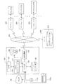
以下、本発明の実施の形態を実施例に基づいて説明する。図1は本発明の一実施例としてのデバイス検索装置を示すブロック図である。
【0031】
本実施例のデバイス装置であるコンピュータ100には、図1に示すように、プリンタAの接続されたコンピュータ200などや、ファクシミリAの接続されたコンピュータ300などや、デジタルカメラAの接続されたコンピュータ600などや、共有データベース部410を備えたサーバ400などが、ネットワーク500を介して接続されている。なお、コンピュータには、パーソナルコンピュータや、モバイルコンピュータ、情報処理端末装置や、ワークステーションなど、種々のコンピュータが含まれる他、実質的にコンピュータ機能を有する複写機やプリンタなどの周辺機器や、同じくコンピュータ機能を有するセット・トップ・ボックス(Set Top Box;例えば、Web TVの受信ターミナルなどに代表される情報端末の一形態)なども含まれる。また、ネットワーク500としては、インターネットや、イントラネットや、ローカルエリアネットワーク(LAN)や、ワイドエリアネットワーク(WAN)など、各種ネットワークを適用することができる。
【0032】
図1に示すように、コンピュータ100は、コンピュータプログラムに従って種々の処理や制御を行なうためのCPU110と、上記コンピュータプログラムを記憶したり、処理中に得られたデータなどを一時的に記憶したりするためのメモリ120と、各種周辺装置との間でデータなどのやり取りを行なうためのI/O部130と、各種データを格納するためのハードディスク装置140と、モデムやターミナルアダプタやネットワークカードなどから成り、ネットワークを介して他の装置と通信を行なうための通信装置150と、CD−ROMドライブ装置160と、ユーザからの指示などを入力するためのキーボード170a及びマウス170bと、CRTや液晶ディスプレイなどから成り、ユーザインターフェイスなどの各種画像を表示することが可能なモニタ180と、を備えている。
【0033】
また、コンピュータ100内のCPU110は、メモリ120に格納されている所望のコンピュータプログラムを読み出して実行することにより、アプリケーション部112として機能する。
【0034】
本実施例では、メモリ120に格納されているコンピュータプログラムは、記録媒体であるCD−ROM162に記録された形態で提供され、CD−ROMドライブ装置160により読み取られることによって、コンピュータ100内に取り込まれる。取り込まれたコンピュータプログラムは、ハードディスク装置140に転送され、その後、起動時などにメモリ120に転送される。あるいは、読み取られたコンピュータプログラムは、ハードディスク装置140を介さず、直接、メモリ120に転送するようにしても良い。
【0035】
このように、本実施例では、コンピュータプログラムをコンピュータ読み取り可能に記録する「記録媒体」としてCD−ROMを利用することを述べたが、その他にも、フレキシブルディスクや光磁気ディスク、ICカード、ROMカートリッジ、パンチカード、バーコードなどの符号が印刷された印刷物、コンピュータの内部記憶装置(RAMやROMなどのメモリ)および外部記憶装置等の、コンピュータが読取り可能な種々の媒体を利用できる。
【0036】
また、コンピュータプログラムは、このような記録媒体に記録された形態での提供の他、ネットワーク500を介して、コンピュータプログラムを供給するプログラムサーバ(図示せず)にアクセスし、プログラムサーバからコンピュータ100内に取り込むようにしても良い。
【0037】
また、上記コンピュータプログラムの一部は、オペレーティングシステムプログラムによって構成するようにしても良い。
【0038】
さらにまた、本実施例においては、アプリケーション部112をソフトウェアによって実現しているが、これをハードウェアによって実現するようにしても良い。
【0039】
一方、サーバ400内の共有データベース部410には、ネットワーク500上に存在する多数のデバイス(例えば、プリンタAやファクシミリAやデジタルカメラAなど)に関する情報が登録されている。具体的には、各デバイスの名称や、各デバイスの属するカテゴリ(すなわち、デバイスクラス)の名称や、各デバイスの持つ機能や、各デバイスの設置場所など、各デバイスをネットワーク500を介して利用するために必要な情報が登録されている。これらの情報は、各デバイスがネットワーク500上の各コンピュータにそれぞれ結合された際に、その結合されたコンピュータにより、予め定められたフォーマットに従って、サーバ400内の共有データベース部410に登録される。
【0040】
また、共有データベース部410には、その他、ネットワーク500を利用している人に関する情報も登録されている。具体的には、各人物の名前や、識別番号や、所属や、居場所など、種々の情報が登録されている。これらの情報は、ネットワーク500の管理者が、管理者用コンピュータにより、予め定められたフォーマットに従って共有データベース部410に登録する。なお、場合によっては、各個人や代表者が登録するようにしても良い。
【0041】
サーバ400は、共有データベース部410に登録されたデバイスに関する情報及び人に関する情報を、すべて、ネットワーク500上に公開する。これによって、ネットワーク500上に存在するコンピュータ100をはじめとする何れのコンピュータからも、登録されたデバイスや人に関する情報を自由に取得して利用することが可能となる。ただし、その公開に制限を加えることにより、例えば、ネットワーク500上の特定のコンピュータからしかアクセスできないようにすることは可能である。
【0042】
なお、このように、ネットワーク500上に存在するどのコンピュータからもアクセスできるよう、ネットワーク500上に情報を公開するには、例えば、Microsoft社製のネットワークOSであるWindows NTなどで用いられているディレクトリサービスなどを利用することによって、実現することができる。すなわち、サーバ400がドメインコントローラとして機能している場合、その共有データベース部410に格納されている情報は、ディレクトリサービスによって、ネットワーク500上のどのコンピュータからも参照し得るようになる。
【0043】
また、本実施例では、デバイスや人に関する情報を特定のコンピュータであるサーバ400に登録するようにしているが、本発明はこれに限定されるものではなく、ネットワーク500上への情報の公開が可能であるなら、ネットワーク500上に存在するコンピュータ100,200,300や、その他コンピュータに登録するようにしても良い。また、デバイス検索装置であるコンピュータ100自体は、動作速度の改善の目的などから、サーバ400の共有データベース部410から、デバイス及び人に関する情報の全部または一部を、予め、自己のハードディスク装置140などにコピーしておき、それを利用するようにしても良い。
【0044】
それでは、本実施例における第1のデバイス検索表示処理について、図2〜図5を用いて説明する。例えば、今、コンピュータ100のユーザが、ネットワーク500を利用している或る人に対して、画像を伝送しようとして、その人の近くにある出力デバイスを検索する場合を考えてみる。なお、以下、このデバイス検索の対象となる人物を対象人物と呼ぶ。
【0045】
図2は図1のアプリケーション部112による第1のデバイス検索表示処理の処理手順を示すフローチャートである。
【0046】
ユーザがマウス170bなどを用いてコンピュータ100に対し、デバイス検索処理の開始を指示すると、図2に示す第1のデバイス検索表示処理が開始され、コンピュータ100内のアプリケーション部112は、図3(a)に示すようなデバイス検索ウインドウ184をモニタ180の画面182上に表示させる(ステップS100)。
【0047】
図3は図1のモニタ180の画面上に表示されたデバイス検索ウインドウを示す説明図である。
【0048】
このように、デバイス検索ウインドウ184が表示されると、ユーザは、キーボード170aなどを用いて、デバイス検索ウインドウ184内の名前入力欄184aに、デバイス検索を行ないたい対象人物の名前を入力する。例えば、図3の例では、対象人物を「Nancy Smith」としており、その「Nancy Smith」という名前を名前入力欄184aに入力している。そして、ユーザは、入力された名前に間違いがないか確認した上で、マウス170bなどを用いて、デバイス検索ウインドウ184内の検索開始ボタン184bを押す。
【0049】
一方、アプリケーション部112は、デバイス検索ウインドウ184を表示させると、検索開始ボタン184bが押されるまで待機する(ステップS102)。そして、ユーザによって検索開始ボタン184bが押されると、アプリケーション部112は、I/O部130,通信装置150を介して、ネットワーク500に接続されたサーバ400にアクセスし(ステップS104)、サーバ400内の共有データベース部410に登録されている情報から、名前入力欄184aに入力された対象人物の名前に関係付けられたデバイスの名称を取得して(ステップS106)、I/O部130を介してハードディスク装置140に格納する。
【0050】
図4は図1の共有データベース部410に格納されているデバイスに関する情報の一例を示す説明図であり、図5は同じく共有データベース部410に格納されている人に関する情報の一例を示す説明図である。
【0051】
前述したように、共有データベース部410には、ネットワーク500上に存在している各デバイスに関する情報が、例えば、図4に示すようなツリー構造となって格納されている。このツリー構造の第1層目には、各デバイスの属するカテゴリ(すなわち、デバイスクラス)の名称などの情報が格納されている。具体的には、ネットワーク500上に存在している各デバイスのカテゴリが、プリンタ、ファクシミリ、デジタルカメラ、スキャナなどであるとすると、それらの名称がそれぞれ格納されることになる。
【0052】
また、第2層目には、ネットワーク500上に存在している個々のデバイスの名称などの情報が格納されている。具体的には、ネットワーク500上に、プリンタA、プリンタB、…、ファクシミリA、ファクシミリB、…などと呼ばれる個々のデバイスが存在する場合、それらの名称が格納されることになる。
【0053】
また、第3層目には、ネットワーク500上に存在している個々のデバイスの設置場所を表す情報が格納されている。具体的には、そのデバイスが設置されているフロアの番号やセクションの名前や番号などである。
【0054】
なお、設置場所を定める単位は、このようなフロアやセクションなどに限定されるものではなく、棟単位や事業所単位などもっと大きな単位を用いても良いし、逆にもっと小さな単位を用いても良い。また、デジタルカメラなど可搬性のあるデバイスについては、通常置かれている場所を便宜的に設置場所としても良い。また、デバイスに関する情報としては、その他、各デバイスの持つ機能などの情報も格納されているが、図4では省略されている。
【0055】
一方、共有データベース部410には、前述したとおり、ネットワーク500を利用している人に関する情報も、図5に示すようなツリー構造となって格納されている。即ち、第1層目には、「Kevin Martin」や「Nancy Smith」など、ネットワーク500を利用している個々の人物の名前などの情報が格納されている。また、第2層目には、それらの人物の通常の居場所などの情報が格納されている。居場所の情報は、図4の設置場所の情報と同様に、フロアの番号やセクションの名前や番号などである。
【0056】
なお、人に関する情報としては、その他、個々の人物の識別番号や所属なども格納されているが、図5では省略されている。
【0057】
そこで、アプリケーション部112は、共有データベース部410にアクセスしたら、まず、人に関する情報のうち、第1層目の名前の情報から、名前入力欄184aに入力された対象人物の名前と一致する名前を検索する。その結果、一致する名前が見つかったら、その名前に対応する第2層目の居場所の情報を取得する。図3(a)の例では、名前入力欄184aに入力された名前は「Nancy Smith」であるので、図5に示す情報から「Nancy Smith」という名前を検索し、それに対応する「フロア2」という居場所の情報を得る。
【0058】
次に、アプリケーション部112は、デバイスに関する情報のうち、第3層目の設置場所の情報から、取得した居場所と一致する設置場所を検索する。そして、一致する設置場所が見つかったら、その設置場所に対応する第2層目のデバイスの名称の情報を取得する。図5の例では、取得した居場所は「フロア2」であったので、図4に示す情報から「フロア2」という設置場所を検索し、それに対応する「プリンタA」,「プリンタC」,「ファクシミリD」というデバイスの名称を得る。
【0059】
このようにして、デバイスの名称を取得すると、次に、アプリケーション部112は、I/O部130を介してモニタ180の画面182上に、取得した各デバイスの名称と対応するアイコンを表示させる(ステップS108)。具体的には、図3(b)に示すように、デバイス検索ウインドウ184内に新たに検索結果表示欄184cが開き、その中に、取得したデバイスの名称、即ち、「プリンタA」,「プリンタC」,「ファクシミリD」と、それに対応するアイコンが表示される。なお、各デバイスに対応するアイコンのデータは、予め、コンピュータ100のハードディスク装置140内に格納していても良いし、サーバ400にアクセスした際に、共有データベース部410から取得するようにしても良い。
【0060】
以上のように、図2に示した第1のデバイス検索表示処理によれば、コンピュータ100のユーザは、デバイス検索を行ないたい対象人物の名前を入力するだけで、ネットワーク上に存在するデバイスの中から、対象人物の近くにある出力デバイスを検索することができる。従って、ユーザは、その検索結果として得られたデバイスの中から所望のデバイスを選択した上で、そのデバイスに対し画像のデータを伝送することにより、その対象人物に対し画像を直ちに届けることが可能となる。
【0061】
次に、本実施例における第2のデバイス検索表示処理について、図6及び図7を用いて説明する。
【0062】
図6は図1のアプリケーション部112による第2のデバイス検索表示処理の処理手順を示すフローチャートであり、図7は図1のモニタ180の画面上に表示された人物アイコンを示す説明図である。
【0063】
今、コンピュータ100のモニタ180の画面182上に、図7(a)に示すように、2つの人物アイコン186a,186bが表示されているものとする。このうち、人物アイコン186aは「Nancy Smith」という人に、人物アイコン186bは「Kevin Martin」という人に、それぞれ、対応するアイコンとなっており、各々の人物の名前と写真画像が表示されている。
【0064】
そこで、コンピュータ100のユーザは、例えば、所望の対象人物の近くにある出力デバイスを検索することを意図して、マウス170bを操作し、画面182上に表示されている人物アイコンの中から、その対象人物の人物アイコンをダブルクリックする。例えば、図7の例では、対象人物を「Nancy Smith」としており、ユーザは、「Nancy Smith」の人物アイコン186aを、マウスカーソル186cで選択してダブルクリックしている。
【0065】
アプリケーション部112は、I/O部130を介して、「Nancy Smith」の人物アイコン186aがダブルクリックされたことを検出すると(ステップS202)、デバイス検索をなすべき対象人物の名前が「Nancy Smith」であることを把握する。そして、アプリケーション部112は、I/O部130,通信装置150を介して、ネットワーク500に接続されたサーバ400にアクセスし(ステップS204)、サーバ400内の共有データベース部410に登録されている情報から、その対象人物の名前に関係付けられたデバイスの名称を取得して(ステップS206)、I/O部130を介してハードディスク装置140に格納する。
【0066】
なお、共有データベース部410に登録されている情報から、対象人物の名前に関係付けられたデバイス名称を取得する方法は、図2の第1のデバイス検索表示処理で述べた方法と同様であるので、説明は省略する。
【0067】
こうして、対象人物の名前に関係付けられたデバイスの名称を取得すると、アプリケーション部112は、I/O部130を介してモニタ180の画面182上に、取得した各デバイスの名称と対応するアイコンを表示させる(ステップS208)。具体的には、図7(b)に示すように、画面182上に、対象人物である「Nancy Smith」に対応した人物ウインドウ188が新たに開き、その中に、取得したデバイスの名称と、それに対応するアイコンが表示される。図7(b)の例では、取得したデバイスの名称を、図3(b)の場合と同様に、「プリンタA」,「プリンタC」,「ファクシミリD」としている。
【0068】
以上のように、図6に示した第2のデバイス検索表示処理によれば、コンピュータ100のユーザは、デバイス検索を行ないたい対象人物のアイコンをダブルクリックするだけで、ネットワーク上に存在するデバイスの中から、対象人物の近くにある出力デバイスを検索することができる。従って、前述した第1のデバイス検索表示処理に比較して、対象人物の名前を入力する手間が省けるので、ユーザの操作性を向上させることが可能となる。
【0069】
次に、本実施例における第3のデバイス検索表示処理について、図8〜図10を用いて説明する。
【0070】
図8は図1のアプリケーション部112による第3のデバイス検索表示処理の処理手順を示すフローチャートであり、図9は図1のモニタ180の画面上に表示された人物アイコンを示す説明図である。
【0071】
今、コンピュータ100のモニタ180の画面182上に、図9(a)に示すように、2つのデバイスアイコン192a,192bと、2つの人物アイコン186a,186bが表示されているものとする。このうち、デバイスアイコン192aは入力デバイスであるデジタルカメラAに、デバイスアイコン192bは同じくデジタルカメラBに、それぞれ、対応するアイコンとなっている。また、人物アイコン186a,186bは、図7に示したのと同様に、「Nancy Smith」,「Kevin Martin」という人に、それぞれ、対応するアイコンとなっている。
【0072】
そこで、コンピュータ100のユーザは、例えば、入力デバイスである所望のデジタルカメラから、所望の対象人物の近くにある出力デバイスに画像を伝送することを意図して、マウス170bを操作し、画面182上に表示されているそのデジタルカメラのアイコンをドラッグし、その対象人物の人物アイコンにドロップする。例えば、図9(a)の例では、所望のデジタルカメラをデジタルカメラA、対象人物を「Nancy Smith」としており、ユーザは、デジタルカメラAのアイコン192aをマウスカーソル186cで選択して、一点鎖線の矢印で示すようにドラッグし、「Nancy Smith」の人物アイコンの位置まで来たら、ドロップする。
【0073】
なお、以下、このドラッグ・アンド・ドロップのなされたデバイスアイコンに対応するデバイス(即ち、デジタルカメラA)を、対象デバイスと呼ぶ。
【0074】
アプリケーション部112は、I/O部130を介して、プリンタAのアイコン192aが「Nancy Smith」の人物アイコン186aにドラッグ・アンド・ドロップされたことを検出すると(ステップS302)、伝送元となるべきデジタルカメラの名称はデジタルカメラAであり、デバイス検索をなすべき対象人物の名前は「Nancy Smith」であることを把握する。そして、アプリケーション部112は、I/O部130,通信装置150を介して、ネットワーク500に接続されたサーバ400にアクセスし(ステップS304)、サーバ400内の共有データベース部410に登録されている情報から、上記した対象人物の名前に関係付けられたデバイスの名称を取得して(ステップS306)、I/O部130を介してハードディスク装置140に格納する。
【0075】
なお、共有データベース部410に登録されている情報から、対象人物の名前に関係付けられたデバイス名称を取得する方法は、図2の第1のデバイス検索表示処理で述べた方法と同様であるので、説明は省略する。
【0076】
次に、アプリケーション部112は、I/O部130,通信装置150を介して、ネットワーク500上に存在する対象デバイスであるデジタルカメラAにアクセスして(ステップS308)、デジタルカメラAにデータが保持されているか否かを判定する(ステップS310)。そして、デジタルカメラAにデータが保持されている場合には、そのデータをデジタルカメラAから読み出して取得し(ステップS312)、ハードディスク装置140に格納する。
【0077】
ここで、アプリケーション部112が対象デバイスであるデジタルカメラAにアクセスして、データの取得を行なう際の手順について、図10を用いて説明する。
【0078】
図10は図1のアプリケーション部112がネットワーク500を介してデバイスにアクセスしてデータの取得を行なう際の構成を示すブロック図である。
【0079】
前述したように、ユーザによって、デジタルカメラAのアイコン192aがドラッグ・アンド・ドロップされたことにより、まず、コンピュータ100内には、デジタルカメラAに対応したインターフェイス部114が生成されると共に、同じくデジタルカメラAに対応したプロキシ(Proxy)116が生成される。これにより、プロキシ116に対応して、デジタルカメラAの接続されたコンピュータ600内には、スタブ(Stub)602が生成される。
【0080】
また、コンピュータ100のCPU110は、ネットワーク500を介して、コンピュータ600に対し、デジタルカメラAに対応したデバイス制御部604を生成するよう指示する。これにより、コンピュータ600内には、デジタルカメラAに対応したデバイス制御部604が生成される。
【0081】
なお、コンピュータ600内には、予め、デジタルカメラAをコンピュータ600に結合した際に、デジタルカメラAに対応したデバイスドライバ606が生成されている。
【0082】
本実施例においては、インターフェイス部114、デバイス制御部604およびプロキシ116,スタブ602を、COMの技術を用いて実現している。
【0083】
ここで、COM(Compornent Object Model)とは、Microsoft社が提唱し、推進しているオブジェクトを連携動作させるインフラストラクチャであって、動的に交換可能なコンポーネントの構築方法を定義するものであり、コンポーネントアーキテクチャの標準を定めた仕様である。
【0084】
COMでは、ソフトウェアが提供するサービスは、それぞれ、COMオブジェクトとしてインプリメントされる。各COMオブジェクトは、それぞれ、1つ以上のインターフェイスを実装している。本実施例では、インターフェイス部114およびデバイス制御部604がCOMオブジェクトとして構成される。
【0085】
一方、プロキシ116及びスタブ602は、COM/DCOM(Distributed COM)の機構により構築されている。COM/DCOMはWindowsプラットホーム等で標準的にサポートされる機構である。
【0086】
なお、COMオブジェクトが実装するインターフェイスは、通常何らかの関連性を持ったいくつかのメソッドによって構成されている。各インターフェイスは、それぞれ、インターフェイスIDにより識別される。また、メソッドは特定の機能を実行する関数呼び出しであって、特定のインターフェイスに含まれるメソッドを呼び出すためには、そのインターフェイスへのポインタが必要となる。インターフェイスのポインタは、そのインターフェイスを識別するインターフェイスIDと、そのインターフェイスを実装するCOMオブジェクトを識別するクラスIDなどを指定して、COMライブラリのサービスを呼び出すことにより取得することができる。
【0087】
以上のようにして、コンピュータ100内にインターフェイス部114とプロキシ116が、デジタルカメラAの結合されたコンピュータ600内にスタブ602とデバイス制御部604が、それぞれ、生成されると、これらは自動的に起動される。これにより、図10に示すように、コンピュータ100内のアプリケーション部112、インターフェイス部114、プロキシ116、ネットワーク500、コンピュータ600内のスタブ602、デバイス制御部604、デバイスドライバ606、並びに、コンピュータ600に結合されたデジタルカメラAが互いに接続されて、アプリケーション部112からネットワーク500を介してデバイスであるデジタルカメラAに至る通信経路が確立され、アプリケーション部112は、ネットワーク500を介してデジタルカメラAを制御して自由に利用することが可能となる。
【0088】
このとき、プロキシ116とスタブ602は、アプリケーション部112がデジタルカメラAとの間でネットワーク500を越えて各種制御情報のやり取りやデータのやり取りを行なう際に、上位に位置するアプリケーション部112やインターフェイス部114に対して、コンピュータ100と600の間をネットワーク500を介して接続する通信路の抽象化を行なう。一方、デバイス制御部604は、対応するデバイス(この場合、デジタルカメラA)のデバイスクラス(デバイスの種類)の違いを吸収して、上位に位置するアプリケーション部112やインターフェイス部114に対して、デバイスの抽象化(ハードウェアの抽象化)を行なう。
【0089】
以上のようにして、アプリケーション部112が、ネットワーク500を介して、デジタルカメラAに保持されているデータを取得して、ハードディスク装置140に格納すると、次に、アプリケーション部112は、格納したデータを読み出して、間引き処理などを施して、サムネイル画像のデータを作成する。そして、図9(b)に示すように、モニタ180の画面182上に、作成したそのサムネイル画像データに基づいてデータアイコンを表示させると同時に、ステップS306で取得した各デバイスの名称と対応するアイコンを表示させる(ステップS314)。
【0090】
すなわち、アプリケーション部112は、図9(b)に示すように、モニタ180の画面182上に、デジタルカメラAに対応するデバイスウインドウ194と「Nancy Smith」に対応する人物ウインドウ196とをそれぞれ開き、デジタルカメラAのデバイスウインドウ194には、デジタルカメラAに保持されている全データのデータアイコンを、「Nancy Smith」の人物ウインドウ196には、デバイス検索により取得したデバイスの名称とアイコンを、それぞれ、同時に表示させる。なお、図9(b)の例では、取得したデバイスの名称を、図3(b)、図7(b)の場合と同様に、「プリンタA」,「プリンタC」,「ファクシミリD」としている。
【0091】
一方、ステップS310において、デジタルカメラAにデータが保持されていない場合には、アプリケーション部112は、前述の図7(b)に示したように、モニタ180の画面182上に、対象人物である「Nancy Smith」に対応した人物ウインドウ188のみを新たに開き、そのウインドウ188内に、取得したデバイスの名称と、それに対応するアイコンを表示させる(ステップS316)。
【0092】
以上のように、図8に示した第3のデバイス検索表示処理によれば、コンピュータ100のユーザは、伝送元であるデジタルカメラのアイコンを、伝送先である対象人物のアイコンにドラッグ・アンド・ドロップするだけで、そのデジタルカメラに保持されているデータと、その対象人物の近くにある出力デバイスとを、画面上に同時に表示させることができるので、ユーザは、伝送したい画像と、伝送先である出力デバイスを一目で把握することができ、さらに、それらの中から所望の画像と所望の出力デバイスとを選んで、例えば、その画像のデータアイコンをその出力デバイスのアイコンにドラッグ・アンド・ドロップすることによって、デジタルカメラAからその出力デバイスへ、所望の画像のデータの伝送を直ちにコンピュータ100に指示することができる。
【0093】
なお、本発明は上記した実施例や実施形態に限られるものではなく、その要旨を逸脱しない範囲において種々の態様にて実施することが可能である。
【0094】
上記した図9の例では、他のコンピュータ600に接続されているデジタルカメラAをデータの伝送元としていたが、本発明はこれに限定されるものではなく、自己のコンピュータ100にローカル接続されている入力デバイス(図示せず)を伝送元としても良いし、或いは、自己のコンピュータ100のハードディスク装置140内に格納されたデータや、ネットワーク500上に存在するWebサイト内のデータを、伝送の対象としても良い。
【0095】
上記した例では、サーバ400の共有データベース部410内に、デバイスに関する情報の一つとしてデバイスの設置場所の情報を、人に関する情報の一つとして人物の居場所の情報を、それぞれ格納して、それらを利用したが、本発明はこれに限定されるものではなく、例えば、図11に示すように、共有データベース部410内に、新たな情報のカテゴリとして場所に関する情報を設け、その情報に、デバイスの設置場所の情報や人物の居場所の情報を含ませて、それらを利用するようにしても良い。
【0096】
図11は図1の共有データベース部410に格納されている場所に関する情報の一例を示す説明図である。即ち、図11に示すように、共有データベース部410内に、ツリー構造を成す場所に関する情報を格納して、デバイスの設置場所や人物の居場所を一元的に管理することにより、データベース内での検索速度をさらに改善することができる。従って、これらの情報を前述したデバイス検索処理に利用することにより、より効率的にデバイス検索を行なうことができる。
【0097】
上記した実施例においては、デバイス検索により取得されるデバイスは出力デバイスであったが、必要に応じて、入力デバイスも、デバイス検索により取得できるようにしても良い。
【0098】
上記した実施例においては、人とデバイスの関係付けを、居場所や設置場所など位置の情報を媒介として行なっていたが、このような位置の関係だけでなく、例えば、デバイスの所有関係や使用関係などの情報を媒介として、関係付けを行なうようにしても良い。
【0099】
また、上記した実施例においては、インターフェイス部114、デバイス制御部604およびプロキシ116,スタブ602を、COMの技術を用いて実現したが、COM以外にも、同様の分散オブジェクトを構築する環境としてJAVA(登録商標)やCORBAなどがあり、これらを用いて同様の機構を実現するようにしても良い。
【0100】
また、アイコンを表示させる代わりに、人物名やデバイス名やデータ名のみの文字を表示させるようにしても良く、また、それらに対応する図形や記号や符号や色彩などを表示させるようにしても良い。
【0101】
上記した実施例においては、モニタ180の画面182上のウインドウ内に、各アイコンを整列して表示させる場合について説明したが、ウインドウ内に各アイコンをツリー構造で表示させるようにしても良い。
【図面の簡単な説明】
【図1】図1は本発明の一実施例としてのデバイス検索装置を示すブロック図である。
【図2】図1のアプリケーション部112による第1のデバイス検索表示処理の処理手順を示すフローチャートである。
【図3】図1のモニタ180の画面上に表示されたデバイス検索ウインドウを示す説明図である。
【図4】図1の共有データベース部410に格納されているデバイスに関する情報の一例を示す説明図である。
【図5】図1の共有データベース部410に格納されている人に関する情報の一例を示す説明図である。
【図6】図1のアプリケーション部112による第2のデバイス検索表示処理の処理手順を示すフローチャートである。
【図7】図1のモニタ180の画面上に表示された人物アイコンを示す説明図である。
【図8】図1のアプリケーション部112による第3のデバイス検索表示処理の処理手順を示すフローチャートである。
【図9】図1のモニタ180の画面上に表示された人物アイコンを示す説明図である。
【図10】図1のアプリケーション部112がネットワーク500を介してデバイスにアクセスしてデータの取得を行なう際の構成を示すブロック図である。
【図11】図1の共有データベース部410に格納されている場所に関する情報の一例を示す説明図である。
【符号の説明】
100…コンピュータ
110…CPU
112…アプリケーション部
114…インターフェイス部
116…プロキシ
120…メモリ
130…I/O部
140…ハードディスク装置
150…通信装置
160…CD−ROMドライブ装置
162…CD−ROM
170a…キーボード
170b…マウス
180…モニタ
182…画面
184…デバイス検索ウインドウ
184a…名前入力欄
184b…検索開始ボタン
184c…検索結果表示欄
186a,186b…人物アイコン
186c…マウスカーソル
188…人物ウインドウ
192a,192b…デバイスアイコン
194…デバイスウインドウ
196…人物ウインドウ
200…コンピュータ
300…コンピュータ
400…サーバ
410…共有データベース部
500…ネットワーク
600…コンピュータ
602…スタブ
604…デバイス制御部
606…デバイスドライバ[0001]
BACKGROUND OF THE INVENTION
The present invention relates to a technique for searching for a device related to a desired person from a plurality of devices existing on a network.
[0002]
[Prior art]
Conventionally, for example, in Windows 95 and Windows NT, which are operating systems made by Microsoft, a network is searched using a computer name as a search condition, a function for searching for a specific computer on the network, and a file name or folder name as a search condition. It had a function of searching for files and folders stored in a specific computer existing above. In addition, Window 98, which is also an OS made by Microsoft, has a function of searching for a specific person's mail address as a search condition for a person's name.
[0003]
[Problems to be solved by the invention]
In general, a plurality of computers are connected to the network, and various devices such as printers, scanners, and facsimiles are connected via the computers or directly. These devices may be owned or used by a person, placed near a person, or installed on the same floor or section where a person is located. And have some relationship with people.
[0004]
Therefore, for example, when you want to deliver a document or image to a person using the network, search for devices related to that person from the devices on the network using the person as a search condition. If it is possible to do so, it is possible to deliver the document or image to the person just by transmitting the data of the document or image to the device obtained thereby, which is very convenient for the user.
[0005]
However, conventionally, as described above, there has been only a function of searching for a specific computer on the network or searching for an e-mail address using a person's name as a search condition.
[0006]
Accordingly, an object of the present invention is to solve the above-described problems of the prior art and to search for a device related to a desired person from a plurality of devices existing on the network, and a device search apparatus therefor A method and a recording medium are provided.
[0007]
[Means for solving the problems and their functions and effects]
To achieve at least a part of the above object, a first device search apparatus according to the present invention searches for a device related to a desired person from a plurality of devices existing on a network. A device,
Display means having a screen;
Input means for inputting instructions from the outside;
Control means;
With
The control means accesses a database existing on the network or in the device search apparatus when the personal expression of the desired person is inputted as a specific personal expression from the outside via the input means, A device notation related to the input specific person notation is acquired from association information representing a relationship between a plurality of person notations stored in a database and a device notation of the device existing on the network. Thus, at least one of the acquired device notation and a device symbol corresponding to the device represented by the device notation is displayed on the screen of the display means.
[0008]
The first device search method of the present invention searches for a device related to a desired person from a plurality of devices existing on the network, and displays the search result on the screen of the display means. A method,
(A) instructing the character notation of the desired person;
(B) Acquiring a device notation associated with the instructed person notation from association information representing a relationship between a plurality of person notations prepared in advance and the device notation of the device existing on the network. And a process of
(C) displaying at least one of the acquired device notation and a device symbol corresponding to the device represented by the device notation on the screen of the display means;
It is a summary to provide.
[0009]
As described above, according to the first device search apparatus or method, by specifying the person expression of a desired person as a search condition, the device expression associated with the person expression or the corresponding device symbol is displayed on the screen. Therefore, the user can easily search for a device related to the person on the network. Therefore, for example, even when the user wants to transmit a desired document or image to the person, the user immediately understands the device related to the person and starts transmission of document or image data toward the device. It becomes possible.
[0010]
In this specification, the relationship between A and B is not limited to the case where A and B are directly related, but the case where A and B are indirectly related (for example, A and C are related to each other). And the like, and C and B are related, and A and B are related via C).
[0011]
In this specification, the device includes not only a physical device such as a printer, a digital camera, a scanner, and a facsimile, but also a part of the function of the physical device or a function equivalent to the physical device by software. (For example, e-mail and image processing) are also included.
[0012]
In addition, in this specification, the person notation or the device notation includes all the notations that can identify the person or device, such as an identification number or a code, in addition to the name of the person or device. Device symbols can be displayed on the screen, such as icons representing symbols corresponding to the device, as well as characters, figures, symbols, symbols, colors, etc., and can be identified by the user. Some are included. This also applies to person symbols and data symbols described later. For example, in the case of a person symbol, a photograph or illustration of the person can be used as a pattern corresponding to the person.
[0013]
A second device search apparatus of the present invention is a device search apparatus for searching for a device related to a desired person from a plurality of devices existing on a network.
Display means having a screen;
Input means for inputting instructions from the outside;
Control means;
With
The control means displays a person symbol corresponding to a person on the screen of the display means,
The selected person symbol when an instruction to select a person symbol corresponding to the desired person from the person symbols displayed on the screen is input from the outside via the input unit The personal representation of a person corresponding to the above is used as a specific personal representation, and a database existing on the network or in the device search apparatus is accessed, and a plurality of personal representations stored in the database and the device existing on the network A device notation associated with the specific person notation is obtained from association information representing an association with the device notation of the device, and the acquired device notation and a device symbol corresponding to the device represented by the device notation The gist is to display at least one on the screen of the display means.
[0014]
The second device search method of the present invention searches for a device related to a desired person from a plurality of devices existing on the network and displays the search result on the screen of the display means. A method,
(A) displaying a person symbol corresponding to a person on the screen of the display means;
(B) selecting a person symbol corresponding to the desired person from the displayed person symbols;
(C) Based on the person representation of the person corresponding to the person symbol selected from the association information representing the association between a plurality of person representations and the device representation of the device existing on the network. Obtaining a device notation associated with the person notation,
(D) displaying at least one of the acquired device notation and a device symbol corresponding to the device represented by the device notation on the screen of the display means;
It is a summary to provide.
[0015]
As described above, according to the second device search apparatus or method, by selecting the person symbol corresponding to the desired person displayed on the screen, the device related to the person notation corresponding to the person symbol. Since the notation or the corresponding device symbol is displayed on the screen, the user can easily search for a device related to the person from the network. In addition, since a device search can be performed simply by selecting a person symbol displayed on the screen, user operability can be improved.
[0016]
A third device search apparatus of the present invention is a device search apparatus for searching for a device related to a desired person from a plurality of devices existing on a network.
Display means having a screen;
Input means for inputting instructions from the outside;
Control means;
With
The control means displays a person symbol corresponding to a person and a device symbol corresponding to a device on the screen of the display means,
An instruction to perform symbol association between a desired first device symbol in the device symbols displayed on the screen and a person symbol corresponding to the desired person is input from the outside via the input unit. In the case where the symbol association is made, the person notation of the person corresponding to the person symbol associated with the symbol is accessed as a specific person notation, and a database existing on the network or in the device search apparatus is accessed and stored in the database. The device representation associated with the specific personal representation is obtained from association information representing the association between a plurality of personal representations and the device representation of the device existing on the network, and the obtained device representation and At least one of the second device symbols corresponding to the device represented by the device notation One is summarized in that to display on the screen of the display means.
[0017]
The third device search method of the present invention searches for a device related to a desired person from a plurality of devices existing on the network and displays the search result on the screen of the display means. A method,
(A) displaying a person symbol corresponding to a person and a device symbol corresponding to a device on the screen of the display means;
(B) performing a symbol association between a desired device symbol in the displayed device symbols and a person symbol corresponding to the desired person;
(C) A person person corresponding to the person symbol associated with the symbol from association information representing a relation between a plurality of person expressions prepared in advance and a device expression of the device existing on the network. Obtaining a device notation associated with the person notation based on the notation;
(D) displaying at least one of the acquired device notation or a device symbol corresponding to the device represented by the device notation on the screen of the display means;
It is a summary to provide.
[0018]
As described above, according to the third device searching apparatus or method, the symbol association between the desired device symbol displayed on the screen and the person symbol corresponding to the desired person is performed, thereby corresponding to the person symbol. Since the device notation related to the person notation or the device symbol corresponding to the device notation is displayed on the screen, the user can easily search for a device related to the person from the network. In addition, since a device search can be performed simply by associating a desired device symbol displayed on the screen with a person symbol, user operability can be improved.
[0019]
In the third device search apparatus of the present invention,
When the device corresponding to the first device symbol holds data, the control means acquires a data symbol corresponding to each held data on the screen of the display means. Preferably, the device notation or the corresponding second device symbol is displayed in an area different from the area where the device notation is displayed.
[0020]
In this configuration, simply associating a device symbol with a person symbol, the data symbol held by the device represented by the device symbol and the device symbol associated with the person are displayed on the screen. Since it is displayed at the same time, the user can immediately know the data held by the device. Also, even if you want to transmit the data to that person, you can immediately know the device related to that person, so you can transmit the data by associating the data symbol with the desired device symbol by mouse operation etc. It can be instructed to start.
[0021]
In the first to third device search apparatuses of the present invention,
The association information includes person position information representing a relation between a position related to a person and the person notation, and device position information representing a relation between a position related to a device and the device notation,
The control means derives a position related to the specific person notation from the person position information, derives a device notation related to the derived position from the device position information, and derives the derived device notation as the specific person notation. You may make it acquire as said device description linked | related to.
[0022]
In order for a person to use a device, it is assumed that the device is near the person. Therefore, by associating the relationship between the person and the device, such as a person's whereabouts and the device installation location, using the positional relationship as an intermediary, it is possible to relate the devices available to the person.
[0023]
The first recording medium of the present invention searches for a device related to a desired person from a plurality of devices existing on a network, and displays the search result on a screen of a display means connected to a computer. A computer-readable recording medium having a computer program recorded thereon,
Association information representing a relationship between a plurality of person representations and device representations of the devices existing on the network, when a personal representation of the desired person is input to the computer from the outside A function to obtain a device notation associated with the inputted person notation,
A function of displaying on the screen of the display means at least one of the acquired device notation and a device symbol corresponding to the device represented by the device notation;
The gist is that a computer program for realizing the above is recorded on the computer.
[0024]
When the computer program recorded on such a recording medium is executed by the computer, the same operation as the control means in the first device search apparatus described above occurs, so the same effect as the first device search apparatus is obtained. Can play.
[0025]
The second recording medium of the present invention searches for a device related to a desired person from a plurality of devices existing on the network, and displays the search result on the screen of the display means connected to the computer. A computer-readable recording medium having a computer program recorded thereon,
A function of displaying a person symbol corresponding to a person on the screen of the display means;
When an instruction to select a person symbol corresponding to the desired person from the person symbols displayed on the screen is input from the outside to the computer, a plurality of person expressions prepared in advance And the device notation related to the person notation based on the person notation of the person corresponding to the selected person symbol from the association information indicating the association between the device and the device notation of the device existing on the network With the ability to get
A function of displaying on the screen of the display means at least one of the acquired device notation and a device symbol corresponding to the device represented by the device notation;
The gist is that a computer program for realizing the above is recorded on the computer.
[0026]
When the computer program recorded on such a recording medium is executed by the computer, the same operation as the control means in the second device search apparatus described above occurs, and therefore the same effect as that of the second device search apparatus is obtained. Can play.
[0027]
The third recording medium of the present invention searches for a device related to a desired person from a plurality of devices existing on the network, and displays the search result on the screen of a display means connected to the computer. A computer-readable recording medium having a computer program recorded thereon,
Displaying a person symbol corresponding to a person and a device symbol corresponding to a device on the screen of the display means;
When an instruction to perform symbol association between a desired device symbol in the device symbols displayed on the screen and a person symbol corresponding to the desired person is input from the outside to the computer in advance From the set association information representing the association between the plurality of person representations and the device representation of the device existing on the network, based on the person representation of the person corresponding to the person symbol associated with the symbol A function for obtaining a device notation associated with the person notation;
A function of displaying on the screen of the display means at least one of the acquired device notation and a device symbol corresponding to the device represented by the device notation;
The gist is that a computer program for realizing the above is recorded on the computer.
[0028]
When the computer program recorded on such a recording medium is executed by the computer, the same operation as the control means in the third device search apparatus described above occurs, and therefore the same effect as that of the third device search apparatus can be obtained. Can play.
[0029]
The device search apparatus, the device search method of the present invention, the function of the device search apparatus or the computer program for realizing the device search method, the recording medium storing the computer program, and the computer program including the computer program embodied in a carrier wave It can be realized in various modes such as a data signal.
[0030]
DETAILED DESCRIPTION OF THE INVENTION
Hereinafter, embodiments of the present invention will be described based on examples. FIG. 1 is a block diagram showing a device search apparatus as an embodiment of the present invention.
[0031]
As shown in FIG. 1, the
[0032]
As shown in FIG. 1, a
[0033]
The
[0034]
In this embodiment, the computer program stored in the
[0035]
As described above, in this embodiment, it is described that the CD-ROM is used as a “recording medium” for recording the computer program in a computer-readable manner, but in addition, a flexible disk, a magneto-optical disk, an IC card, a ROM Various types of computer-readable media such as cartridges, punched cards, printed matter on which codes such as bar codes are printed, computer internal storage devices (memory such as RAM and ROM), and external storage devices can be used.
[0036]
Further, the computer program is provided in a form recorded in such a recording medium, and also accesses a program server (not shown) that supplies the computer program via the
[0037]
A part of the computer program may be constituted by an operating system program.
[0038]
Furthermore, in the present embodiment, the
[0039]
On the other hand, in the shared
[0040]
In addition, in the shared
[0041]
The
[0042]
In this way, in order to publish information on the
[0043]
In this embodiment, information about devices and people is registered in the
[0044]
The first device search / display process in this embodiment will be described with reference to FIGS. For example, consider a case in which a user of the
[0045]
FIG. 2 is a flowchart showing a processing procedure of first device search display processing by the
[0046]
When the user uses the
[0047]
FIG. 3 is an explanatory view showing a device search window displayed on the screen of the
[0048]
As described above, when the
[0049]
On the other hand, when displaying the
[0050]
FIG. 4 is an explanatory diagram showing an example of information related to devices stored in the shared
[0051]
As described above, the shared
[0052]
In the second layer, information such as names of individual devices existing on the
[0053]
In the third layer, information indicating the installation location of each device existing on the
[0054]
The unit that determines the installation location is not limited to such floors or sections, but larger units such as building units or business units may be used, or conversely smaller units may be used. good. Further, for a portable device such as a digital camera, the place where it is usually placed may be set as the installation place for convenience. In addition, as information on the device, other information such as functions of each device is also stored, but is omitted in FIG.
[0055]
On the other hand, as described above, the shared
[0056]
In addition, as the information about the person, the identification number and affiliation of each person are also stored, but are omitted in FIG.
[0057]
Therefore, when accessing the shared
[0058]
Next, the
[0059]
When the device name is acquired in this way, the
[0060]
As described above, according to the first device search and display process shown in FIG. 2, the user of the
[0061]
Next, the second device search display process in the present embodiment will be described with reference to FIGS.
[0062]
FIG. 6 is a flowchart showing the processing procedure of the second device search display process by the
[0063]
Assume that two
[0064]
Therefore, for example, the user of the
[0065]
When the
[0066]
Note that the method for acquiring the device name related to the name of the target person from the information registered in the shared
[0067]
When the name of the device related to the name of the target person is acquired in this way, the
[0068]
As described above, according to the second device search display process shown in FIG. 6, the user of the
[0069]
Next, a third device search display process in the present embodiment will be described with reference to FIGS.
[0070]
FIG. 8 is a flowchart showing a third device search display processing procedure by the
[0071]
Assume that two
[0072]
Therefore, for example, the user of the
[0073]
Hereinafter, the device corresponding to the dragged and dropped device icon (that is, the digital camera A) is referred to as a target device.
[0074]
When the
[0075]
Note that the method for acquiring the device name related to the name of the target person from the information registered in the shared
[0076]
Next, the
[0077]
Here, a procedure when the
[0078]
FIG. 10 is a block diagram showing a configuration when the
[0079]
As described above, when the
[0080]
Further, the
[0081]
In the
[0082]
In the present embodiment, the
[0083]
Here, COM (Compornent Object Model) is an infrastructure that promotes and promotes the objects proposed and promoted by Microsoft, and defines a method for constructing dynamically replaceable components. A specification that defines the standard for component architecture.
[0084]
In COM, each service provided by software is implemented as a COM object. Each COM object implements one or more interfaces. In the present embodiment, the
[0085]
On the other hand, the proxy 116 and the stub 602 are constructed by a mechanism of COM / DCOM (Distributed COM). COM / DCOM is a mechanism that is supported as standard on Windows platforms and the like.
[0086]
Note that the interface implemented by the COM object is usually composed of several methods having some relationship. Each interface is identified by an interface ID. A method is a function call for executing a specific function, and in order to call a method included in a specific interface, a pointer to the interface is required. The interface pointer can be obtained by calling a COM library service by designating an interface ID for identifying the interface and a class ID for identifying a COM object that implements the interface.
[0087]
As described above, when the
[0088]
At this time, when the
[0089]
As described above, when the
[0090]
That is, as shown in FIG. 9B, the
[0091]
On the other hand, if no data is stored in the digital camera A in step S310, the
[0092]
As described above, according to the third device search and display process shown in FIG. 8, the user of the
[0093]
The present invention is not limited to the above-described examples and embodiments, and can be implemented in various modes without departing from the scope of the invention.
[0094]
In the example of FIG. 9 described above, the digital camera A connected to the
[0095]
In the above-described example, in the shared
[0096]
FIG. 11 is an explanatory diagram showing an example of information relating to a location stored in the shared
[0097]
In the above embodiment, the device acquired by the device search is the output device. However, if necessary, the input device may be acquired by the device search.
[0098]
In the above-described embodiment, the relationship between the person and the device is performed using the location information such as the whereabouts and the installation location as a medium. The association may be performed using information such as this as a medium.
[0099]
In the above-described embodiment, the
[0100]
Also, instead of displaying icons, characters such as person names, device names, and data names may be displayed, and corresponding figures, symbols, symbols, colors, etc. may be displayed. good.
[0101]
In the above-described embodiment, the case where the icons are arranged and displayed in the window on the
[Brief description of the drawings]
FIG. 1 is a block diagram showing a device search apparatus as an embodiment of the present invention.
FIG. 2 is a flowchart showing a processing procedure of first device search display processing by an
3 is an explanatory diagram showing a device search window displayed on the screen of the
4 is an explanatory diagram illustrating an example of information on a device stored in a shared
FIG. 5 is an explanatory diagram showing an example of information related to a person stored in a shared
6 is a flowchart showing a processing procedure of second device search display processing by an
7 is an explanatory diagram showing a person icon displayed on the screen of the
FIG. 8 is a flowchart showing a processing procedure of third device search display processing by the
FIG. 9 is an explanatory diagram showing a person icon displayed on the screen of the
10 is a block diagram showing a configuration when an
FIG. 11 is an explanatory diagram showing an example of information regarding a location stored in a shared
[Explanation of symbols]
100: Computer
110 ... CPU
112 ... Application section
114 ... interface section
116 ... Proxy
120 ... memory
130 ... I / O section
140. Hard disk device
150 ... Communication device
160 ... CD-ROM drive device
162 ... CD-ROM
170a ... Keyboard
170b ... Mouse
180 ... Monitor
182 ... Screen
184 ... Device search window
184a ... Name input field
184b ... Search start button
184c ... Search result display field
186a, 186b ... person icon
186c ... Mouse cursor
188 ... People window
192a, 192b ... Device icon
194 ... Device window
196 ... People window
200: Computer
300 ... Computer
400 ... server
410 ... Shared database section
500 ... Network
600 ... Computer
602 ... Stub
604 ... Device control unit
606: Device driver
Claims (2)
通信路を介して接続される第1及び第2のコンピュータを備え、
前記第1のコンピュータは、
アプリケーション部と、
前記データデバイスに対応して実現されるインターフェイス部と、
前記データデバイスに対応して実現されるプロキシと、を備え、
前記第2のコンピュータは、
前記プロキシと前記通信路を介して接続され、前記プロキシに対応して実現されるスタブと、
前記データデバイスに対応して実現されるデバイス制御部と、
前記データデバイスに対応するデバイスドライバと、を備え、
前記アプリケーション部が、
人物に対応した人物シンボルと、データに対応したデータシンボルと、を前記第1のコンピュータが備える表示手段にそれぞれ1以上、同時に表示させると共に、
前記第1のコンピュータが備える入力手段を介して、前記表示された1以上のデータシンボルの中の一つである指定データシンボルと、前記表示された1以上の人物シンボルの中の一つである指定人物シンボルと、がドラッグアンドドロップによって関連づけされた場合に、
前記指定人物シンボルに対応した人物の表記である特定人物表記を取得し、
前記第1のコンピュータが備えるデータベースであって、出力デバイスと前記出力デバイスの設置場所との情報を関連づけて含むデバイス位置情報と、人物の表記と前記人物の居場所との情報を関連づけて含む人物位置情報と、を含む前記データベースにアクセスし、前記人物位置情報を参照して、前記特定人物表記に基づいて、前記人物の居場所の情報を取得し、前記デバイス位置情報を参照して、前記人物の居場所と前記設置場所が一致する1以上の出力デバイスの情報を取得し、
前記情報を取得された1以上の出力デバイスに対応した1以上の出力デバイスシンボルを前記表示手段に表示させ、
前記入力手段を介して、前記表示された1以上の出力デバイスシンボルの中の一つを選択する旨の指示が入力された場合に、前記指定データシンボルに対応するデータを、前記選択された出力デバイスシンボルに対応する出力デバイスに伝送して、出力させる、
処理において、
前記指定データシンボルに対応するデータを格納する前記データデバイスから、前記インターフェイス部,プロキシ,スタブ,デバイス制御部,及びデバイスドライバを介して、データを取得する際に、
前記プロキシ及びスタブは、上位に位置する前記アプリケーション部及びインターフェイス部に対して、前記通信路の抽象化を行なうと共に、
前記デバイス制御部は、前記デバイスのデバイスクラスの違いを吸収して、上位に位置する前記アプリケーション部及びインターフェイス部に対して、デバイスの抽象化を行なうことを特徴とするデバイス制御システム。A device control system for obtaining the data from a data device holding data,
A first computer and a second computer connected via a communication path;
The first computer is
An application section;
An interface unit implemented corresponding to the data device;
A proxy implemented corresponding to the data device,
The second computer is
A stub connected to the proxy via the communication path and realized corresponding to the proxy;
A device control unit realized corresponding to the data device;
A device driver corresponding to the data device,
The application part is
One or more person symbols corresponding to a person and data symbols corresponding to data are simultaneously displayed on the display means provided in the first computer, respectively,
The designated data symbol that is one of the one or more displayed data symbols and one of the one or more person symbols that are displayed via an input means included in the first computer When the specified person symbol is linked by drag and drop,
Obtain a specific person notation that is a person notation corresponding to the designated person symbol,
A database provided in the first computer, the device position information including information relating to the output device and the installation location of the output device, and the person position including information relating to the person's notation and the location of the person Access to the database including information, refer to the person position information, acquire information on the person's whereabouts based on the specific person notation, refer to the device position information, and Obtain information on one or more output devices whose location and installation location match,
Displaying on the display means one or more output device symbols corresponding to the one or more output devices from which the information has been acquired;
When an instruction to select one of the displayed one or more output device symbols is input via the input means, data corresponding to the designated data symbol is output to the selected output. Transmit to the output device corresponding to the device symbol and output it.
In processing
From the data device for storing data corresponding to the designated data symbols, said interface unit, a proxy, stub, the device controller, and via a device driver, when acquiring data,
The proxy and stub perform abstraction of the communication path for the application unit and interface unit located at the upper level,
The device control unit absorbs a difference in device class of the device and performs device abstraction for the application unit and the interface unit positioned at a higher level.
前記アプリケーション部は、前記データデバイスに保持されているデータを取得した場合に、前記データに基づいて、前記表示部に前記データを表すデータアイコンを表示させることを特徴とするデバイス制御システム。The device control system according to claim 1.
When the data stored in the data device is acquired, the application unit displays a data icon representing the data on the display unit based on the data .
Priority Applications (1)
| Application Number | Priority Date | Filing Date | Title |
|---|---|---|---|
| JP2002344282A JP4483169B2 (en) | 2002-11-27 | 2002-11-27 | Device control system |
Applications Claiming Priority (1)
| Application Number | Priority Date | Filing Date | Title |
|---|---|---|---|
| JP2002344282A JP4483169B2 (en) | 2002-11-27 | 2002-11-27 | Device control system |
Related Parent Applications (1)
| Application Number | Title | Priority Date | Filing Date |
|---|---|---|---|
| JP9119699A Division JP2000285039A (en) | 1999-03-31 | 1999-03-31 | Device retrieving device, its method and recording medium recording computer program for realizing the method |
Publications (3)
| Publication Number | Publication Date |
|---|---|
| JP2003202945A JP2003202945A (en) | 2003-07-18 |
| JP2003202945A5 JP2003202945A5 (en) | 2006-06-01 |
| JP4483169B2 true JP4483169B2 (en) | 2010-06-16 |
Family
ID=27655867
Family Applications (1)
| Application Number | Title | Priority Date | Filing Date |
|---|---|---|---|
| JP2002344282A Expired - Fee Related JP4483169B2 (en) | 2002-11-27 | 2002-11-27 | Device control system |
Country Status (1)
| Country | Link |
|---|---|
| JP (1) | JP4483169B2 (en) |
Families Citing this family (1)
| Publication number | Priority date | Publication date | Assignee | Title |
|---|---|---|---|---|
| JP2008010993A (en) * | 2006-06-27 | 2008-01-17 | Kyocera Mita Corp | Electronic apparatus, application executing system, and program |
-
2002
- 2002-11-27 JP JP2002344282A patent/JP4483169B2/en not_active Expired - Fee Related
Also Published As
| Publication number | Publication date |
|---|---|
| JP2003202945A (en) | 2003-07-18 |
Similar Documents
| Publication | Publication Date | Title |
|---|---|---|
| US9626132B2 (en) | Printing device, printing method, computer program product, and recording medium | |
| US8363242B2 (en) | Image processing apparatus and image processing apparatus control method for requesting an external apparatus to transmit image data | |
| JP4049173B2 (en) | Data communication system, image processing apparatus, and data management method in image processing apparatus | |
| JP2001350599A (en) | Image print controller and method for image printing, computer-readable recording medium with program for printing image recorded thereon, and image management system | |
| US10075597B2 (en) | Image processing apparatus having file server function, and control method and storage medium therefor | |
| JP2008071154A (en) | Program and layout plan forming device | |
| US10180814B2 (en) | User terminal, image processing device and cloud server to identify plural user information to execute an image processing job upon validating an user information | |
| JP5278921B2 (en) | Scan management system, scan management apparatus, control method thereof, and program | |
| US20110292460A1 (en) | Information processing system, information processing apparatus, control method thereof, and storage medium | |
| JP4501723B2 (en) | Image processing apparatus, image processing method, and program | |
| WO2000058841A1 (en) | Device searcher and its method, and recording medium on which computer program for realizing it is recorded | |
| JP2010003127A (en) | Document management device, document management system, document management method and computer program | |
| JP4501338B2 (en) | Device control apparatus, user interface display method, and computer readable medium storing computer program for displaying user interface | |
| JP3740919B2 (en) | Device control apparatus, user interface display method, and recording medium recording computer program for displaying user interface | |
| JP3864650B2 (en) | Device control apparatus, user interface display method, and recording medium recording computer program for displaying user interface | |
| JP4483169B2 (en) | Device control system | |
| JP4587844B2 (en) | Data transmission apparatus, image forming apparatus, data transmission method, and computer program | |
| JP2004288055A (en) | Service processing system, service processing method and service processing program | |
| JP2007242038A (en) | Document management device | |
| JP2007081771A (en) | Job processor and job requesting device | |
| JP2019139463A (en) | Information management device | |
| JP2001061032A (en) | Image processor | |
| JP2005292908A (en) | System, program and method for service providing, and job management system | |
| JP5573998B2 (en) | Management system, management apparatus, control method thereof, and program | |
| JP4592253B2 (en) | Document management device |
Legal Events
| Date | Code | Title | Description |
|---|---|---|---|
| A521 | Request for written amendment filed |
Free format text: JAPANESE INTERMEDIATE CODE: A523 Effective date: 20060331 |
|
| A621 | Written request for application examination |
Free format text: JAPANESE INTERMEDIATE CODE: A621 Effective date: 20060331 |
|
| A131 | Notification of reasons for refusal |
Free format text: JAPANESE INTERMEDIATE CODE: A131 Effective date: 20080729 |
|
| A521 | Request for written amendment filed |
Free format text: JAPANESE INTERMEDIATE CODE: A523 Effective date: 20080917 |
|
| A131 | Notification of reasons for refusal |
Free format text: JAPANESE INTERMEDIATE CODE: A131 Effective date: 20090721 |
|
| A521 | Request for written amendment filed |
Free format text: JAPANESE INTERMEDIATE CODE: A523 Effective date: 20090924 |
|
| TRDD | Decision of grant or rejection written | ||
| A01 | Written decision to grant a patent or to grant a registration (utility model) |
Free format text: JAPANESE INTERMEDIATE CODE: A01 Effective date: 20100302 |
|
| A01 | Written decision to grant a patent or to grant a registration (utility model) |
Free format text: JAPANESE INTERMEDIATE CODE: A01 |
|
| A61 | First payment of annual fees (during grant procedure) |
Free format text: JAPANESE INTERMEDIATE CODE: A61 Effective date: 20100315 |
|
| R150 | Certificate of patent or registration of utility model |
Free format text: JAPANESE INTERMEDIATE CODE: R150 |
|
| FPAY | Renewal fee payment (event date is renewal date of database) |
Free format text: PAYMENT UNTIL: 20130402 Year of fee payment: 3 |
|
| LAPS | Cancellation because of no payment of annual fees |