JP4482774B2 - Dispensing and conveying equipment for food ingredients with excellent hygienic properties - Google Patents
Dispensing and conveying equipment for food ingredients with excellent hygienic properties Download PDFInfo
- Publication number
- JP4482774B2 JP4482774B2 JP36897499A JP36897499A JP4482774B2 JP 4482774 B2 JP4482774 B2 JP 4482774B2 JP 36897499 A JP36897499 A JP 36897499A JP 36897499 A JP36897499 A JP 36897499A JP 4482774 B2 JP4482774 B2 JP 4482774B2
- Authority
- JP
- Japan
- Prior art keywords
- belt
- discharge port
- belt conveyor
- conveyor
- conveying
- Prior art date
- Legal status (The legal status is an assumption and is not a legal conclusion. Google has not performed a legal analysis and makes no representation as to the accuracy of the status listed.)
- Expired - Fee Related
Links
Images


Classifications
-
- Y—GENERAL TAGGING OF NEW TECHNOLOGICAL DEVELOPMENTS; GENERAL TAGGING OF CROSS-SECTIONAL TECHNOLOGIES SPANNING OVER SEVERAL SECTIONS OF THE IPC; TECHNICAL SUBJECTS COVERED BY FORMER USPC CROSS-REFERENCE ART COLLECTIONS [XRACs] AND DIGESTS
- Y02—TECHNOLOGIES OR APPLICATIONS FOR MITIGATION OR ADAPTATION AGAINST CLIMATE CHANGE
- Y02P—CLIMATE CHANGE MITIGATION TECHNOLOGIES IN THE PRODUCTION OR PROCESSING OF GOODS
- Y02P60/00—Technologies relating to agriculture, livestock or agroalimentary industries
- Y02P60/80—Food processing, e.g. use of renewable energies or variable speed drives in handling, conveying or stacking
- Y02P60/85—Food storage or conservation, e.g. cooling or drying
Landscapes
- Food Preservation Except Freezing, Refrigeration, And Drying (AREA)
- Specific Conveyance Elements (AREA)
- Filling Or Emptying Of Bunkers, Hoppers, And Tanks (AREA)
Description
【0001】
【産業上の利用分野】
この発明は、主として食品工業ならびに醸造工業に使用するサニタリ性に優れた原料の搬送分配装置に関するものである。
【0002】
【従来の技術】
複数のタンクに原料を投入する場合には、柔軟性のあるホースを利用可能な空気輸送が主に用いられていた。柔軟性のあるホースの末端にサイクロンを設け、タンクの上部にこのサイクロンを固定していた。このサイクロンを空のタンクの上に順次移動することで、複数のタンクに原料を投入していた。
【0003】
【発明が解決しようとする課題】
原料の搬送に空気輸送を使用する場合、末端のサイクロンから排出される原料以外に、微粉末を含んだ送風空気が排出されるため、タンク周辺に粉塵が飛散していた。このため、サニタリ性を要求される環境では、タンクの周辺の洗浄や周辺空気の浄化が大きな問題となっている。
【0004】
原料を搬送する空気輸送の投入口からタンク近傍までは、工場内の動線を考慮して高所に配設した固定配管を用いることが多いが、分解して洗浄する必要があり多大の労力を要している。また、固定配管に接続する柔軟性のあるフレキシブルホースは、原料と接触する内部に緩やかな凹凸があるため微粉末の固着堆積が発生しやすく、洗浄を困難にしている。更に、サニタリ性維持に重要な要素となる洗浄状態と配管内の乾燥は、目視による確認ができないため、HACCP方式の導入に支障をきたしている。
【0005】
ここで、HACCP方式とは、危害の発生を事前に予防するシステムであって、品質管理のために最終製品のサンプル検査を行う方法とは異なり、食品の原材料の段階から、製造、出荷、消費までの各段階で、食品の「危害H」発生につながる危険要因を調査、分析、予測し、予測された危害を防除するため特に重要な管理が必要な作業工程や検査工程を「重要管理点CCP」として管理するシステムである。
【0006】
通常のフラットベルトコンベアを使用すると、外部からの異物を混入とリターン側ベルトからの原料の飛散、及び受ローラによるベルト搬送面の汚染が問題となる。
【0007】
タンクへのサイクロンによる原料投入では、固定されたサイクロンから排出される原料がタンク内部に堆積するため、凸状の山型堆積となる。また、複数のタンクに原料を投入する場合には、サイクロンを移動させる必要がある。さらに、空気輸送は、電力消費量を多く必要としている。
【0008】
この発明の課題は、タンク周辺への汚染を防止し、洗浄が充分に行え、目視確認が可能であり、外部からの異物の混入を防止し、複数のタンクに対して自動的に凹凸のない堆積状態で原料投入を行いながら電力消費量の少ない、サニタリ性に優れた食品原料の分配搬送装置を提供することにある。
【0009】
【課題を解決するための手段】
この発明の請求項1では、複数のタンク(1a〜1f)の側方に沿って第1コンベアベルト(2)を設け、この第1コンベアベルト(2)の搬送側にベルトを分岐突出した第1排出口(4)を設け、この第1排出口(4)を第1ベルトコンベア(2)の搬送方向に移動可能とし、前記第1排出口(4)から原料を受け取る第2ベルトコンベア(9)は前記第1ベルトコンベア(2)に対して交差するように設け、この第2ベルトコンベア(9)は前記第1排出口(4)の移動と連動して前記第1ベルトコンベア(2)の配設方向に移動可能とし、更に前記第2ベルトコンベア(9)はその配設方向に移動可能とし、この第2ベルトコンベア(9)の排出口が前記タンク(1a〜1f)の開口部上の水平面を2次元方向に移動するものとし、かつ前記第1排出口(4)が前記第1ベルトコンベア(2)の搬送方向に移動する場合には、搬送部(6)のベルトを供給側から前記第1排出口(4)に向かって、順次受けローラ(23)を円弧状から円形状に変形させ、この搬送部(6)のベルトを円筒状に形成し、前記第1排出口(4)が前記第1ベルトコンベア(2)の搬送方向とは逆に移動する場合には、前記搬送部(6)のベルトを前記第1排出口(4)から供給側に向かって、順次受けローラ(23)を円形状から円弧状に変形させ、前記搬送部(6)のベルトを円筒状に形成するものである。
【0010】
この発明の請求項2では、複数のタンク(1a〜1f)の側方に沿って第1コンベアベルト(2)を設け、この第1コンベアベルト(2)の搬送側にベルトを分岐突出した第1排出口(4)を設け、この第1排出口(4)を第1ベルトコンベア(2)の配設方向に移動可能とし、前記第1排出口(4)から原料を受け取る第2ベルトコンベア(9)は前記第1ベルトコンベア(2)に対して交差するように設け、この第2ベルトコンベア(9)は前記第1排出口(4)の移動と連動して前記第1ベルトコンベア(2)の配設方向に移動可能とし、更に前記第2ベルトコンベア(9)の排出口が前記タンク(1a〜1f)の開口部上の水平面を2次元方向に移動するものとし、かつ前記第1排出口(4)が前記第1ベルトコンベア(2)の搬送方向に移動する場合には、非搬送部(8)のベルトを前記第1排出口(4)から供給側に向かって、順次受けローラ(23)を円形状から円弧状に変形させ非搬送部(8)のベルトを円弧状に形成し、この第1排出口(4)が前記第1ベルトコンベア(2)の搬送方向とは逆に移動する場合には、非搬送部(8)のベルトを排出側から前記第1排出口(4)に向かって、順次前記受けローラ(23)を円形状に変形させこの搬送部(8)のベルトを円筒状にする。
【0011】
【発明の実施の形態】
以下、図面によりこの発明の実施例を説明する。
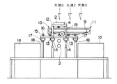
図1は、この初笑みのサニタリ性に優れた食品原料の分配搬送装置の配置を示す平面図である。図2は、図1に示す矢視Aの位置における装置正面の断面図である。図3は、図2に示す矢視Bにおける装置側面の断面図である。図4は、図2に示す矢視Cの位置における装置側面の断面図である。図5は、図2に示す矢視Dの位置における断面図である。図6は、ベルトを支持する受けローラの動きを示すフロー図である。図7は、液体洗浄装置と送風乾燥装置の配置を示す側面の断面図である。図8は、駆動ワイヤによる受けローラの駆動機構を示す正面図である。図9は、パワーシリンダによる受けローラの駆動機構の使用態様の一形態を示す正面図である。図11は、図9に示す駆動機構の使用状態の他の態様を示す正面図である。
【0012】
この発明の基本態様を図1により説明する。2列に配列したタンク1aから1fの間に、第1bベルトコンベア2を設ける。第1ベルトコンベア2には、供給ベルトコンベア3により原料が供給されるが、他の原料供給方法を使用してもよい。第1ベルトコンベア2は、図3に示すように、原料の搬送面にベルトを分岐突出させた第1排出口4を設けている。供給ベルトコンベア3により第1ベルトコンベア2に原料が供給される供給部5から第1排出口4までの原料を搬送する部分を搬送部とし、第1排出口4から折り返して移動ローラ7により水平移動する部分を非搬送部8とする。第1排出口4は移動ローラ7と共に、第1ベルトコンベア2上を移動することができる。
【0013】
非搬送部8には、直接的な機能はないが、突出した第1排出口4を形成するために設けた移動ローラ7により、原料を搬送することのない非搬送部8が発生する。ただし、非搬送部8に異物が落下してベルトに付着した場合、搬送部において原料に混入する危険性があるため、丸める必要がある。
【0014】
第1排出口4と非搬送部8の間には、第1ベルトコンベア2と交差するように第2ベルトコンベア9を設ける。第2ベルトコンベア9のタンク1aから1c側の末端を第2A排出口10とし、タンク1dから1f側の末端を第2B排出口11とする。第2ベルトコンベア9は、第1排出口4と連動して第1ベルトコンベア2上を移動することができる。さらに、第2ベルトコンベア9自体が、第2ベルトコンベア9の配設方向に移動することができる。
【0015】
図1中に示す黒矢印は、ベルトの進行方向を示し、白抜き矢印は第1排出口4と第2ベルトコンベア9の移動方向を示す。
【0016】
第1ベルトコンベア2から原料の供給を受ける第2ベルトコンベア9が、第1ベルトコンベア2の配設方向に移動でき、第2ベルトコンベア9自体が第2ベルトコンベア9の配設方向に移動することができるため、第2A排出口10は、タンク1aの開口部上の水平面を2次元的に自在に移動することができる。
【0017】
第2A排出口10の位置を制御することで、タンク1aの開口部上の水平面を2次元的に順次移動させ、タンク1aの内部へ原料を均一に分散させながら投入することができる。第2A排出口10の位置を固定した場合には、タンク1aの内部には原料が山型の堆積状態となり、サニタリ性の劣る空気輸送と同様の状態となる。原料が山型の堆積状態となると、後工程で水により浸漬する場合には浸漬時間が不均一となり、水の使用量も増加し、以後の工程で発酵する場合には発酵状態が不均一となる。
【0018】
また、タンク1bと1cにも同様に、第1排出口4と第2A排出口10の移動により均一な原料の投入ができる。第2ベルトコンベア9の搬送方向を反転すると、タンク1dからタンク1fにも均一な原料の投入ができる。タンク1dからタンク1fの配列中に、タンク1eのように位置がずれていても、タンクの位置を制御装置に入れることで、問題なく原料の投入が可能である。図示していないが、第1ベルトコンベア2の両側又は片側に複数列のタンクを配置しても、第2ベルトコンベア2の両側又は片側に複数列のタンクを配置しても、第2ベルトコンベア9を対応できる長さ設計することで対応することができる。同様に、1列のタンクの本数も、第1ベルトコンベア2を対応できる長さで設計することで対応することができる。
【0019】
原料を排出した後のベルトコンベア面は、原料の付着等により汚染されやすい。常に清浄な状態を維持するためには、ベルトコンベアが原料の搬送中での洗浄と乾燥が必要となる。汚染状態には原料の相違や季節変動がある。このため、洗浄乾燥後のベルトコンベアの原料接触面を監視可能とし、洗浄が不足していれば洗浄装置の能力を増加させ、乾燥が不足していれば乾燥装置の能力を増加させる。必要以上の洗浄乾燥が行われていれば、各装置の能力を減少させる。この洗浄乾燥方法により、適度の洗浄乾燥を行いベルトコンベアの原料接触面を清浄に維持しながら、原料を分配搬送することができる。
【0020】
図2に示すように、第2ベルトコンベア9は、第1ベルトコンベア2の第1排出口4と非搬送部8の間に挟みこまれる形状で設ける。第1排出口4を支える移動フレーム12には第1A車輪13を設け、第1Aレール14上を移動する。移動フレーム12には第2レール15が固定され、支持ローラ16により第2ベルトコンベア9を支持している。第2レール15には第1B車輪17を設け、第1Bレール18上を移動フレーム12と共に移動する。
【0021】
移動フレーム12の中を貫通するように第1ベルトコンベア2と交差する形状で第2ベルトコンベア9を設けている。第2ベルトコンベア9は正逆転可能な駆動装置により回転する駆動軸19により、第2レール15上を移動することができる。移動フレーム12は第1排出口4と共に移動ローラ7を支持し、駆動フレーム12が移動することで第1排出口4が第1ベルトコンベア2上を移動することができる。図4に示す破線は移動フレーム12の前後に固定した移動ワイヤ20であり、第1Aレール13の両端に設けたワイヤローラ21を支点としている。ワイヤローラ21の何れかを正逆転可能な駆動装置により回転させることで、移動フレーム12を第1ベルトコンベア2の配設方向に移動させる。移動フレーム12の第1A車輪14を正逆転可能な駆動装置により回転する駆動輪として駆動フレーム12を移動させてもよい。
【0022】
第1排出口4の移動に伴って第2ベルトコンベア9が移動し、第2ベルトコンベア9が第2レール15上を移動することにより、第2A排出口10はタンク1aからタンク1cの開口部上の水平面を2次元方向に自在に移動することができる。また、第2ベルトコンベア9のベルト移動方向を逆転可能とすることで、第2B排出口11はタンク1dからタンク1fまでの開口部上の水平面を2次元方向に自在移動することができる。
【0023】
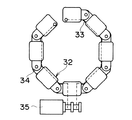
第1ベルトコンベア2と第2ベルトコンベア9の下面に位置するリターン側ベルトは、スクレーパで除去しきれない付着物を、工場床面に飛散させながら移動する。また、リターン側ではベルトの原料接触面ガ受ローラと直接接触するため、ベルトだけを洗浄乾燥しても、多数設けた受ローラにより再度汚染されてしまう。そのため、図6に示すように、リターン側のベルト22の原料接触面に受ローラ23を設ける。移動ローラ7やコンベア両端のベルトローラ24近傍ではベルト22が平面であるため、図6の(A)に示す円弧状とする。順次受ローラ23を円形状に構成することで、ベルト22を円筒状にすることができる。円筒状のベルト22は原料接触面が内側になり、付着物質を飛散させることがない。また、受ローラ23はベルト22の原料接触面と接触しないため、付着物質に汚染されることがなく、洗浄乾燥後のベルト22を再汚染することも防止できる。
【0024】
ベルト22の洗浄乾燥は、図7に示す洗浄装置25と乾燥装置26を使用する。洗浄装置25はベルトコンベア24bからリターン側へ移動した後の、ベルト22が平面状の位置に設ける。洗浄装置25には、薬液や水を噴出可能な液体ノズル27と廃液を回収する回収ボックス28で構成する。工場の床面に排水ピットが設けてある場合には、回収ボックス28をも設けなくてもよい。洗浄能力はポンプの吐出能力を制御して噴出圧力や噴出量を変化させる。液体自動弁29を利用して複数の液体ノズル27を設け、洗浄能力を制御してもよい。また、配管を複数設け、薬液と水を別配管で噴出させてもよい。
【0025】
乾燥装置26は洗浄装置25の次に設け、ベルト22の洗浄面に気体ノズル30aにより空気を吹き付け液体を除去する。乾燥能力の調整には、吐出風量と吐出温度を調整する。気体自動弁31を利用して複数の気体ノズル30を設け、乾燥能力を制御してもよい。気体ノズル30bを円筒状になる直前のベルト22の内側に設け、円筒状のベルト22の内部に空気を送り込んでもよい。
【0026】
原料接触面の監視方法には、近赤外線分光分析法が適している。近赤外線分光分析法は、
近赤外線を照射してその反射光を感知分析することで、有機物の種類の濃度及び水分の濃度を測定できる。近赤外線分光分析装置には、近赤外線を照射してその反射光を感知するセンサ部と、近赤外線の光源や反射光を分析する演算部等からなる本体を柔軟性のあるグラスファイバーで接続し、オンラインで測定可能な装置が市販されている。
【0027】
近赤外線分光分析装置のセンサ部を、第1ベルトコンベア2のベルトローラ24a近傍に設け、ベルト22の原料搬送面の洗浄状態と乾燥状態を監視する。ベルト22の洗浄状態が不良の場合には、近赤外線分光分析装置が所定濃度以上の原料由来の有機物を感知し、その信号により洗浄能力を増加させるように制御する。ベルトの乾燥状態が不良の場合には、近赤外線分光分析装置が所定濃度以上の水分を感知し、その信号により乾燥能力を増加させるように制御する。なお、近赤外線分光分析装置は有機物の種類と濃度を測定できるため、ベルト22が有機物であっても、原料由来の汚染物質を識別にて測定することができる。
第2ベルトコンベア9に対しても、同様の監視装置を設けてもよい。
【0028】
搬送部6のベルト22は原料を輸送しているため、上方から落下する異物が原料へ混入する危険性が高い。しかし、第1排出口4が第1ベルトコンベア2上を移送するため、図6に示すように、ベルト22を円筒状に丸め、原料を包み込んで搬送することができない。そこで、複数の受ローラ23で構成する受ローラ支持体32の形状を図6の(A)から図6の(D)に示すように自動的に変更可能とする。
【0029】
受ローラ支持体32の形状を変更する機構として、図8に示す駆動ワイヤ33による開閉機構がある。各受ローラ23の長軸方向荷に連結金具34を設け、駆動ワイヤ33を貫通する受ローラ23をチェ-―ン上に連結する。受ローラ支持体32が8個の受ローラ23で構成される場合、連結金具34には、連結する受ローラ23と受ローラ23の長軸の内角が135°以下にならないようにストッパを設けてもよい。受ローラ23と受ローラ23の長軸の内角は、受ローラ23の使用個数により変動させ、おおむね円形となるようにする。受ローラ支持体32の先端に位置する受ローラ23の内部に駆動ワイヤ33の一端を固定し、各受ローラ23の内部を貫通して下方の固定された受ローラ23から駆動ワイヤ33の一端を出す。この駆動ワイヤを巻取装置35に接続し、駆動ワイヤ33を伸長及び短縮可能とする。
【0030】
駆動ワイヤ33が短縮した状態では、図8のように、受ローラ支持体32の形状が円形となる。駆動ワイヤ33が伸長すると、丸められていたベルト22の弾性による復元力により、受ローラ支持体32の形状が徐々に円弧状となる。このため、巻取装置35の制御により受ローラ支持体32の形状は、円形状から円弧状まで自在に調整することができる。
【0031】
受ローラ支持体32の形状を変更するための聞こうとして、図9に示すパワーシリンダ33による開閉機構がある。受ローラ支持体32の先端に位置する受ローラ23の側部にも同様の連結金具34を設け、パワーシリンダ36と接続する。
【0032】
パワーシリンダ33が伸長した状態では、図9のように、受ローラ支持体32の形状は円形状となる。パワーシリンダ33が収縮した状態では、図9Bのように、受ローラ支持体32の形状が円弧状となる。このため、パワーシリンダ33の制御により受ローラ支持体32の形状は、円形状{図9}から円弧状{図10}まで自在に調整することができる。
【0033】
第1排出口4が第1ベルトコンベア2上を搬送方向に移動する場合、搬送部6の第1排出口4側のベルト22は、移動フレーム12に固定された受ローラ支持体32により円筒状に丸められる。第1排出口4が第1ベルトコンベア2上を搬送方向とは逆に移動する場合、搬送部6の第1排出口4側のベルト22は。移動フレーム12に固定された受ローラ支持体32により円弧状に広げられる。この際、第1ベルトコンベア2に沿ってベルトローラ24aからベルトローラ24bまでの間に設けた受ローラ支持体32の中で、移動フレーム12に近接した受ローラ支持体32は円弧状に広げられ、移動フレーム12の移動を妨げないようにする。
【0034】
第1排出口4が第1ベルトコンベア2上を搬送方向に移動する場合、非搬送部8の移動ローラ7側のベルト22は、ベルトローラ24aからベルトローラ24bまでの間に設けた受ローラ支持体32が円弧状に広げられ、円筒状の形状を解除される。第1排出口4が第1ベルトコンベア2上を搬送方向とは逆に移動する場合、非搬送部8の移動ローラ7側のベルト22は、ベルトローラ24aからベルトローラ24bまでの間に設けた受ローラ支持体32が円筒状に丸められ、円筒状の形状になる。
【0035】
【発明の効果】
ベルトコンベアを使用することで、原料の搬送に空気を使用する必要がなくなり、タンク周辺に粉塵を飛散させることなく、サニタリ性を要求される環境で使用することができる。また、原料をはんそうしながら、自動的に洗浄乾燥をすることができる。更に、リターン側のベルトを円筒状に丸めて移動させるため、受ローラと原料接触面が接触することがなく、返送ベルトからの原料の飛散、及び受ローラによるベルト搬送面の汚染が問題とならない。搬送時においてもベルトを円筒状に丸めて移動させるため、外部からの異物の混入を防止できる。特に、サニタリ性維持に重要な要素となる洗浄状態と乾燥状態は、目視による確認が可能であり、HACCP制度に対応することができる。
【0036】
原料投入口がタンクの形状に応じて自在に移動可能なため、原料はタンク内部に山型堆積とならず、均一な平面状の堆積となり、また、複数のタンクに原料を投入する場合でも、自動的に原料投入口を移動させることができる。さらに、空気輸送の電力消費量と比較してベルトコンベアは少ない電力消費量で稼動することができる。
【0037】
以上の効果により、タンク周辺への汚染を防止し、洗浄が自動的に行え目視確認が可能であり、外部からの異物の混入を防止し、複数のタンクに対して自動的に凹凸のない堆積状態で原料投入を行いながら電力消費量の少ない、サニタリ性の優れた食品原料の分配搬送装置を提供することができる。
【図面の簡単な説明】
【図1】 この発明のサニタリ性に優れた食品原料の分配搬送装置の配置を示す平面図である。
【図2】 図1に示す矢印Aの位置における装置正面の断面図である。
【図3】図2に示す矢印Bの位置における装置側面の断面図である。
【図4】図2に示す矢印Cの位置における装置側面の断面図である。
【図5】図2に示す矢印Dの位置における装置側面の断面図である。
【図6】ベルトを支持する受ローラの動きを示すフロー図である。
【図7】液体洗浄装置と送風乾燥装置の配置を示す側面の断面図である。
【図8】駆動ワイヤによる受ローラの駆動機構を示す正面図である。
【図9】パワーシリンダによる受ローラの駆動機構の使用状態の一形態を示す正面図である。
【図10】図9に示す駆動機構の使用状態の他の形態を示す正面図である。
【符号の説明】
1a―f タンク
2 第1ベルトコンベア
3 救急ベルトコンベア
4 第1排出口
5 供給部
6 搬送部
7 移動ローラ
8 非搬送部
9 第2ベルトコンベア
10 第2A排出口(原料排出口)
11 第2B排出口(原料排出口)
12 移動フレーム
13 第1A車輪
14 第1Aレール
15 第2レール
16 支持レール
17 第1B車輪
18 第1Bレール
19 駆動輪
20 移動ワイヤ
21 ワイヤロープ
22 ベルト
23 受ローラ
24a−bベルトローラ
25 液体洗浄装置
26 送風乾燥装置
27 液体ノズル
28 回収ボックス
29 液体自動弁
30a−b気体ノズル
31 気体自動弁
32 受ローラ支持体
33 駆動ワイヤ
34 連結金具
35 巻取装置
36 パワーシリンダ[0001]
[Industrial application fields]
TECHNICAL FIELD The present invention relates to a raw material conveying / distributing device which is mainly used in the food industry and brewing industry and has excellent sanitary properties.
[0002]
[Prior art]
In the case where raw materials are charged into a plurality of tanks, pneumatic transportation using a flexible hose has been mainly used. A cyclone was provided at the end of the flexible hose, and this cyclone was fixed to the top of the tank. By moving this cyclone sequentially over empty tanks, raw materials were put into a plurality of tanks.
[0003]
[Problems to be solved by the invention]
When pneumatic transportation is used for conveying the raw material, dust is scattered around the tank because blown air containing fine powder is discharged in addition to the raw material discharged from the cyclone at the end. For this reason, in an environment where sanitary properties are required, cleaning around the tank and purification of the surrounding air are major problems.
0004
From the inlet of pneumatic transportation for transporting raw materials to the vicinity of the tank, fixed piping placed in high places is often used in consideration of the flow line in the factory. Is needed. In addition, a flexible hose that is connected to a fixed pipe has loose irregularities inside the material that comes in contact with the raw material, so that fine powder is likely to adhere and accumulate, making cleaning difficult. In addition, the cleaning condition and the drying in the pipes, which are important elements for maintaining sanitary properties, cannot be visually confirmed, which hinders the introduction of the HACCP method.
[0005]
Here, the HACCP method is a system that prevents the occurrence of harm in advance, and unlike the method of inspecting the final product for quality control, it is manufactured, shipped and consumed from the raw material stage of food. At each stage, the risk factors that lead to the occurrence of food “hazard H” are investigated, analyzed, and predicted, and work processes and inspection processes that require particularly important management to control the predicted hazards are designated as “critical control points”. It is a system managed as CCP.
[0006]
When a normal flat belt conveyor is used, there are problems such as contamination of foreign matters from outside, scattering of raw materials from the return side belt, and contamination of the belt conveyance surface by the receiving rollers.
[0007]
When the raw material is introduced into the tank by the cyclone, the raw material discharged from the fixed cyclone is accumulated inside the tank, and thus a convex mountain-shaped deposition is formed. In addition, when a raw material is charged into a plurality of tanks, it is necessary to move the cyclone. Furthermore, pneumatic transportation requires a large amount of power consumption.
[0008]
The object of the present invention is to prevent contamination around the tank, to perform sufficient cleaning, to allow visual confirmation, to prevent foreign matter from entering from outside, and to automatically prevent unevenness in a plurality of tanks. An object of the present invention is to provide a food material distribution / conveyance device that consumes less power while depositing raw materials in a deposited state and has excellent sanitary properties.
[0009]
[Means for Solving the Problems]
In the first aspect of the present invention, the first conveyor belt (2) is provided along the side of the plurality of tanks (1a to 1f), and the belt is branched and protruded on the conveying side of the first conveyor belt (2). 1 Discharge port (4) is provided, this 1st discharge port (4) can be moved in the transport direction of the 1st belt conveyor (2), and the 2nd belt conveyor ( 9) is provided so as to intersect the first belt conveyor (2), and the second belt conveyor (9) is linked to the movement of the first discharge port (4) and the first belt conveyor (2 ) And the second belt conveyor (9) can be moved in the arrangement direction. The discharge port of the second belt conveyor (9) is the opening of the tank (1a to 1f). The horizontal plane on the section moves in a two-dimensional direction, and the first discharge port (4) is the first belt conveyor (2) When moving in the transport direction, the receiving roller (23) is sequentially deformed from an arc shape to a circular shape by moving the belt of the transport section (6) from the supply side toward the first discharge port (4). When the belt of the section (6) is formed in a cylindrical shape and the first discharge port (4) moves in the direction opposite to the transport direction of the first belt conveyor (2), the transport section (6) The receiving roller (23) is sequentially deformed from a circular shape to an arc shape from the first discharge port (4) toward the supply side, and the belt of the conveying section (6) is formed into a cylindrical shape. .
[0010]
According to
[0011]
DETAILED DESCRIPTION OF THE INVENTION
Embodiments of the present invention will be described below with reference to the drawings.
FIG. 1 is a plan view showing the arrangement of a food material distribution / conveyance device excellent in the sanitary nature of the first smile. FIG. 2 is a cross-sectional view of the front of the apparatus at the position of arrow A shown in FIG. 3 is a cross-sectional view of the side surface of the apparatus in the direction of arrow B shown in FIG. 4 is a cross-sectional view of the side surface of the apparatus at the position of arrow C shown in FIG. FIG. 5 is a cross-sectional view at the position of arrow D shown in FIG. FIG. 6 is a flowchart showing the movement of the receiving roller that supports the belt. FIG. 7 is a side cross-sectional view showing the arrangement of the liquid cleaning device and the air blowing / drying device. FIG. 8 is a front view showing a driving mechanism of the receiving roller by the driving wire. FIG. 9 is a front view showing an embodiment of a usage mode of a receiving roller driving mechanism using a power cylinder. FIG. 11 is a front view showing another mode of use of the drive mechanism shown in FIG.
[0012]
A basic embodiment of the present invention will be described with reference to FIG. A
[0013]
Although the
[0014]
Between the
[0015]
A black arrow shown in FIG. 1 indicates a traveling direction of the belt, and a white arrow indicates a moving direction of the
0016
The
[0017]
By controlling the position of the second
[0018]
Similarly, the raw materials can be uniformly fed into the tanks 1b and 1c by the movement of the
[0019]
The belt conveyor surface after the raw material is discharged is easily contaminated by the adhesion of the raw material. In order to maintain a clean state at all times, the belt conveyor needs to be washed and dried while the raw material is being conveyed. There are differences in raw materials and seasonal variations in the pollution status. For this reason, the raw material contact surface of the belt conveyor after washing and drying can be monitored, and if the washing is insufficient, the ability of the washing apparatus is increased, and if the drying is insufficient, the ability of the drying apparatus is increased. If washing and drying is performed more than necessary, the capacity of each device is reduced. By this cleaning / drying method, it is possible to distribute and convey the raw material while performing appropriate cleaning / drying to keep the raw material contact surface of the belt conveyor clean.
[0020]
As shown in FIG. 2, the
[0021]
A
[0022]
As the
[0023]
The return-side belts located on the lower surfaces of the
[0024]
For cleaning and drying of the
[0025]
The drying
[0026]
Near-infrared spectroscopy is suitable as a method for monitoring the material contact surface. Near-infrared spectroscopy is
By irradiating near-infrared rays and sensing and analyzing the reflected light, it is possible to measure the concentration of organic substances and the concentration of moisture. The near-infrared spectroscopic analyzer has a flexible glass fiber that connects a sensor unit that irradiates near-infrared rays and senses the reflected light to a body that includes a near-infrared light source and a calculation unit that analyzes the reflected light. On-line measuring devices are commercially available.
[0027]
A sensor unit of the near-infrared spectroscopic analyzer is provided in the vicinity of the
A similar monitoring device may be provided for the
[0028]
Since the
[0029]
As a mechanism for changing the shape of the receiving
[0030]
When the
[0031]
As an attempt to change the shape of the receiving
[0032]
In a state where the
0033
When the
[0034]
When the
[0035]
【The invention's effect】
By using a belt conveyor, it is not necessary to use air for conveying raw materials, and it can be used in an environment where sanitary properties are required without scattering dust around the tank. In addition, washing and drying can be performed automatically while the raw materials are mixed. Furthermore, since the return side belt is rolled into a cylindrical shape and moved, the receiving roller and the material contact surface do not come into contact with each other, and the scattering of the material from the return belt and the contamination of the belt conveyance surface by the receiving roller do not become a problem. . Even during conveyance, the belt is rolled and moved in a cylindrical shape, so that foreign matters can be prevented from being mixed in from the outside. In particular, the washing and drying conditions, which are important elements for maintaining sanitary properties, can be visually confirmed, and can be applied to the HACCP system.
[0036]
Since the raw material input port can move freely according to the shape of the tank, the raw material does not accumulate in a mountain shape inside the tank, it becomes a uniform flat accumulation, and even when the raw material is charged into multiple tanks, The raw material inlet can be moved automatically. Furthermore, the belt conveyor can be operated with less power consumption than the power consumption of pneumatic transportation.
[0037]
Due to the above effects, contamination around the tank can be prevented, cleaning can be performed automatically and visual confirmation is possible, foreign matter can be prevented from entering from the outside, and there can be no unevenness in multiple tanks automatically. It is possible to provide a food material distribution / conveyance device that consumes less power and that has excellent sanitary properties while being charged with raw materials.
[Brief description of the drawings]
FIG. 1 is a plan view showing an arrangement of a food material distribution / conveyance device excellent in hygienic properties according to the present invention.
FIG. 2 is a cross-sectional view of the front of the apparatus at the position of arrow A shown in FIG.
3 is a cross-sectional view of the side surface of the device at the position of arrow B shown in FIG.
4 is a cross-sectional view of the side surface of the apparatus at the position of arrow C shown in FIG.
FIG. 5 is a cross-sectional view of the side surface of the apparatus at the position of arrow D shown in FIG.
FIG. 6 is a flowchart showing the movement of the receiving roller that supports the belt.
FIG. 7 is a side cross-sectional view showing the arrangement of the liquid cleaning device and the air blowing and drying device.
FIG. 8 is a front view showing a driving mechanism of a receiving roller by a driving wire.
FIG. 9 is a front view showing one form of a usage state of a driving mechanism of a receiving roller by a power cylinder.
10 is a front view showing another form of use of the drive mechanism shown in FIG.
[Explanation of symbols]
1a-
11 2B outlet (raw material outlet)
12 moving
Claims (2)
Priority Applications (1)
| Application Number | Priority Date | Filing Date | Title |
|---|---|---|---|
| JP36897499A JP4482774B2 (en) | 1999-12-27 | 1999-12-27 | Dispensing and conveying equipment for food ingredients with excellent hygienic properties |
Applications Claiming Priority (1)
| Application Number | Priority Date | Filing Date | Title |
|---|---|---|---|
| JP36897499A JP4482774B2 (en) | 1999-12-27 | 1999-12-27 | Dispensing and conveying equipment for food ingredients with excellent hygienic properties |
Publications (2)
| Publication Number | Publication Date |
|---|---|
| JP2001180826A JP2001180826A (en) | 2001-07-03 |
| JP4482774B2 true JP4482774B2 (en) | 2010-06-16 |
Family
ID=18493244
Family Applications (1)
| Application Number | Title | Priority Date | Filing Date |
|---|---|---|---|
| JP36897499A Expired - Fee Related JP4482774B2 (en) | 1999-12-27 | 1999-12-27 | Dispensing and conveying equipment for food ingredients with excellent hygienic properties |
Country Status (1)
| Country | Link |
|---|---|
| JP (1) | JP4482774B2 (en) |
Families Citing this family (2)
| Publication number | Priority date | Publication date | Assignee | Title |
|---|---|---|---|---|
| JP2023142182A (en) * | 2022-03-24 | 2023-10-05 | 清水建設株式会社 | Concrete conveyance equipment and how to adjust the length of concrete conveyance equipment |
| JP2023142197A (en) * | 2022-03-24 | 2023-10-05 | 清水建設株式会社 | Concrete conveyance equipment and concrete conveyance method |
-
1999
- 1999-12-27 JP JP36897499A patent/JP4482774B2/en not_active Expired - Fee Related
Also Published As
| Publication number | Publication date |
|---|---|
| JP2001180826A (en) | 2001-07-03 |
Similar Documents
| Publication | Publication Date | Title |
|---|---|---|
| JP5162153B2 (en) | Sprouts conveyor equipment | |
| CN111417586A (en) | Transport system for containers in the beverage industry and method of lubrication | |
| US4667690A (en) | Bottle washing apparatus | |
| CN105942550B (en) | A kind of skinning machine | |
| CN105564936A (en) | Self-cleaning feed discharge conveying device | |
| KR101833456B1 (en) | Cleaning apparatus for profile | |
| JP4482774B2 (en) | Dispensing and conveying equipment for food ingredients with excellent hygienic properties | |
| US3986476A (en) | Apparatus for coating a liquid on opposite sides of a flexible sheet material | |
| CN106423706A (en) | Coating equipment and coating method | |
| US20200102668A1 (en) | Cotton seed processing | |
| CN106418599A (en) | Potato cleaning device | |
| KR101479119B1 (en) | Manufacturing apparatus for cabbage kimchi | |
| JP2005296886A (en) | Pallet cleaning device and cleaning method | |
| JP3333713B2 (en) | Cleaning device for airborne conveyor | |
| EP2799372A1 (en) | A method and a processing station for processing shell eggs | |
| KR100473542B1 (en) | Painting device for a tetragonal pipe | |
| KR100724315B1 (en) | Egg Oil Coating System | |
| KR100209216B1 (en) | Belt cleaning device and cleaning method | |
| JP4423879B2 (en) | Automatic conveyance draining apparatus and automatic draining method for articles, automatic cleaning apparatus and automatic cleaning method for articles | |
| JP3543171B2 (en) | Bottle processing equipment for recycling | |
| JPH026100A (en) | Apparatus for cleaning adhesive powder on tablet | |
| US20070119382A1 (en) | Bedding dispensing system and method | |
| CN217133388U (en) | Food foreign matter detection equipment | |
| CN205708644U (en) | A kind of automatically cleaning conveying device being applicable to viscosity fermented feed | |
| JP2000051327A (en) | Can lid sterilizer |
Legal Events
| Date | Code | Title | Description |
|---|---|---|---|
| A711 | Notification of change in applicant |
Free format text: JAPANESE INTERMEDIATE CODE: A711 Effective date: 20040813 |
|
| A521 | Request for written amendment filed |
Free format text: JAPANESE INTERMEDIATE CODE: A821 Effective date: 20040813 |
|
| A621 | Written request for application examination |
Free format text: JAPANESE INTERMEDIATE CODE: A621 Effective date: 20061225 |
|
| A977 | Report on retrieval |
Free format text: JAPANESE INTERMEDIATE CODE: A971007 Effective date: 20090928 |
|
| A131 | Notification of reasons for refusal |
Free format text: JAPANESE INTERMEDIATE CODE: A131 Effective date: 20091020 |
|
| A521 | Request for written amendment filed |
Free format text: JAPANESE INTERMEDIATE CODE: A523 Effective date: 20091126 |
|
| TRDD | Decision of grant or rejection written | ||
| A01 | Written decision to grant a patent or to grant a registration (utility model) |
Free format text: JAPANESE INTERMEDIATE CODE: A01 Effective date: 20100216 |
|
| A01 | Written decision to grant a patent or to grant a registration (utility model) |
Free format text: JAPANESE INTERMEDIATE CODE: A01 |
|
| A61 | First payment of annual fees (during grant procedure) |
Free format text: JAPANESE INTERMEDIATE CODE: A61 Effective date: 20100310 |
|
| R150 | Certificate of patent or registration of utility model |
Free format text: JAPANESE INTERMEDIATE CODE: R150 Ref document number: 4482774 Country of ref document: JP Free format text: JAPANESE INTERMEDIATE CODE: R150 |
|
| FPAY | Renewal fee payment (event date is renewal date of database) |
Free format text: PAYMENT UNTIL: 20130402 Year of fee payment: 3 |
|
| R250 | Receipt of annual fees |
Free format text: JAPANESE INTERMEDIATE CODE: R250 |
|
| R250 | Receipt of annual fees |
Free format text: JAPANESE INTERMEDIATE CODE: R250 |
|
| R250 | Receipt of annual fees |
Free format text: JAPANESE INTERMEDIATE CODE: R250 |
|
| R250 | Receipt of annual fees |
Free format text: JAPANESE INTERMEDIATE CODE: R250 |
|
| R250 | Receipt of annual fees |
Free format text: JAPANESE INTERMEDIATE CODE: R250 |
|
| R250 | Receipt of annual fees |
Free format text: JAPANESE INTERMEDIATE CODE: R250 |
|
| LAPS | Cancellation because of no payment of annual fees |