JP4481985B2 - Mandrel for hole cutters and related uses - Google Patents
Mandrel for hole cutters and related uses Download PDFInfo
- Publication number
- JP4481985B2 JP4481985B2 JP2006517656A JP2006517656A JP4481985B2 JP 4481985 B2 JP4481985 B2 JP 4481985B2 JP 2006517656 A JP2006517656 A JP 2006517656A JP 2006517656 A JP2006517656 A JP 2006517656A JP 4481985 B2 JP4481985 B2 JP 4481985B2
- Authority
- JP
- Japan
- Prior art keywords
- mandrel
- hole
- pin
- bearing surface
- support member
- Prior art date
- Legal status (The legal status is an assumption and is not a legal conclusion. Google has not performed a legal analysis and makes no representation as to the accuracy of the status listed.)
- Expired - Lifetime
Links
- 238000000034 method Methods 0.000 claims description 9
- 230000002093 peripheral effect Effects 0.000 claims description 2
- 239000002184 metal Substances 0.000 description 9
- 238000012986 modification Methods 0.000 description 2
- 230000004048 modification Effects 0.000 description 2
- 230000036346 tooth eruption Effects 0.000 description 2
- 239000003795 chemical substances by application Substances 0.000 description 1
- 239000000463 material Substances 0.000 description 1
- 239000002893 slag Substances 0.000 description 1
Images


Classifications
-
- B—PERFORMING OPERATIONS; TRANSPORTING
- B23—MACHINE TOOLS; METAL-WORKING NOT OTHERWISE PROVIDED FOR
- B23B—TURNING; BORING
- B23B51/00—Tools for drilling machines
- B23B51/04—Drills for trepanning
- B23B51/0473—Details about the connection between the driven shaft and the tubular cutting part; Arbors
-
- B—PERFORMING OPERATIONS; TRANSPORTING
- B23—MACHINE TOOLS; METAL-WORKING NOT OTHERWISE PROVIDED FOR
- B23B—TURNING; BORING
- B23B51/00—Tools for drilling machines
- B23B51/04—Drills for trepanning
-
- B—PERFORMING OPERATIONS; TRANSPORTING
- B23—MACHINE TOOLS; METAL-WORKING NOT OTHERWISE PROVIDED FOR
- B23B—TURNING; BORING
- B23B31/00—Chucks; Expansion mandrels; Adaptations thereof for remote control
- B23B31/008—Chucks; Expansion mandrels; Adaptations thereof for remote control with arrangements for transmitting torque
-
- B—PERFORMING OPERATIONS; TRANSPORTING
- B23—MACHINE TOOLS; METAL-WORKING NOT OTHERWISE PROVIDED FOR
- B23B—TURNING; BORING
- B23B31/00—Chucks; Expansion mandrels; Adaptations thereof for remote control
- B23B31/02—Chucks
- B23B31/10—Chucks characterised by the retaining or gripping devices or their immediate operating means
- B23B31/107—Retention by laterally-acting detents, e.g. pins, screws, wedges; Retention by loose elements, e.g. balls
- B23B31/1075—Retention by screws
- B23B31/1076—Retention by screws with conical ends
-
- B—PERFORMING OPERATIONS; TRANSPORTING
- B23—MACHINE TOOLS; METAL-WORKING NOT OTHERWISE PROVIDED FOR
- B23B—TURNING; BORING
- B23B51/00—Tools for drilling machines
- B23B51/04—Drills for trepanning
- B23B51/0426—Drills for trepanning with centering devices
-
- B—PERFORMING OPERATIONS; TRANSPORTING
- B23—MACHINE TOOLS; METAL-WORKING NOT OTHERWISE PROVIDED FOR
- B23B—TURNING; BORING
- B23B2270/00—Details of turning, boring or drilling machines, processes or tools not otherwise provided for
- B23B2270/54—Methods of turning, boring or drilling not otherwise provided for
-
- Y—GENERAL TAGGING OF NEW TECHNOLOGICAL DEVELOPMENTS; GENERAL TAGGING OF CROSS-SECTIONAL TECHNOLOGIES SPANNING OVER SEVERAL SECTIONS OF THE IPC; TECHNICAL SUBJECTS COVERED BY FORMER USPC CROSS-REFERENCE ART COLLECTIONS [XRACs] AND DIGESTS
- Y10—TECHNICAL SUBJECTS COVERED BY FORMER USPC
- Y10T—TECHNICAL SUBJECTS COVERED BY FORMER US CLASSIFICATION
- Y10T408/00—Cutting by use of rotating axially moving tool
- Y10T408/89—Tool or Tool with support
- Y10T408/895—Having axial, core-receiving central portion
-
- Y—GENERAL TAGGING OF NEW TECHNOLOGICAL DEVELOPMENTS; GENERAL TAGGING OF CROSS-SECTIONAL TECHNOLOGIES SPANNING OVER SEVERAL SECTIONS OF THE IPC; TECHNICAL SUBJECTS COVERED BY FORMER USPC CROSS-REFERENCE ART COLLECTIONS [XRACs] AND DIGESTS
- Y10—TECHNICAL SUBJECTS COVERED BY FORMER USPC
- Y10T—TECHNICAL SUBJECTS COVERED BY FORMER US CLASSIFICATION
- Y10T408/00—Cutting by use of rotating axially moving tool
- Y10T408/94—Tool-support
- Y10T408/95—Tool-support with tool-retaining means
Landscapes
- Engineering & Computer Science (AREA)
- Mechanical Engineering (AREA)
- Drilling Tools (AREA)
- Milling Processes (AREA)
- Harvester Elements (AREA)
- Supports For Plants (AREA)
- Processing Of Stones Or Stones Resemblance Materials (AREA)
Description
本出願は、2003年6月24日に出願された「ホールカッタのための心軸及び関連する使用方法」という名称の米国予備特許出願第60/482,170号、及び2004年6月23日に速達郵便第EV482066660US号及び管理番号第97309.00110号として出願された同様の名称の米国実用新案出願の優先権を主張しており、それらの開示内容は、本開示の一部として参照によってここに明示的に援用されている。 This application is filed on June 24, 2003, US Provisional Patent Application No. 60 / 482,170 entitled “Axis for Hole Cutters and Related Uses”, and Express on June 23, 2004. Claims priority of US utility model applications of similar name filed under Postal Code EV482066660US and Control Number 97309.00110, the disclosures of which are expressly incorporated herein by reference as part of this disclosure. Has been incorporated.
本発明は、心軸及び心軸の使用方法、特に、心軸に対するソーの軸ぶれを防ぐホールソー又はその他のホールカッタのための心軸及び心軸の使用方法に関する。 The present invention relates to a mandrel and a method of using the mandrel, and more particularly to a mandrel and a mandrel using a mandrel for a hole saw or other hole cutter that prevents the shaft from shaking relative to the mandrel.
ホールソー又はその他のホールカッタのための典型的な心軸は、ねじ山付き端部を規定する心軸本体を含んでおり、この端部は、ホールソーの端板内にねじ留め的に係合可能であり、ホールソーを心軸にしっかりと固定する。パイロットドリルが心軸本体のねじ山付き端部の内部に受容可能であり、ホールソーの中心を通って延在している。心軸本体はショルダを規定し、これは、ねじ山付き端部に軸方向に間隔を空けて隣接しており、ホールソーの端板に係合可能である。心軸は更にピンリングを含み、これは、ねじ山付き端部から軸方向に間隔を空けられており、セットねじによって心軸本体にしっかりと固定される。駆動板が、ねじ山付き端部に対してピンリングの反対側で心軸本体にスライド可能に搭載されており、一対の直径方向に対向する駆動ピンを含み、これらはピンリングに形成された対応する貫通孔内に延在している。駆動ピンの端は、ホールソーの端板に形成された対応する駆動孔に受容されて、ホールソーを回転可能に駆動する。ロックナットが、ピンリングに対して駆動板の反対側で心軸本体にねじ留め的に搭載されている。 A typical mandrel for a hole saw or other hole cutter includes a mandrel body that defines a threaded end that can be threadably engaged within the end plate of the hole saw. The hole saw is firmly fixed to the core shaft. A pilot drill is receivable within the threaded end of the mandrel body and extends through the center of the hole saw. The mandrel body defines a shoulder, which is axially adjacent to the threaded end and engageable with the end plate of the hole saw. The mandrel further includes a pin ring, which is axially spaced from the threaded end and is secured to the mandrel body by a set screw. A drive plate is slidably mounted on the mandrel body opposite the pin ring with respect to the threaded end and includes a pair of diametrically opposed drive pins that are formed in the pin ring It extends into the corresponding through hole. The end of the drive pin is received in a corresponding drive hole formed in the end plate of the hole saw to drive the hole saw rotatably. A lock nut is screwed onto the mandrel body opposite the drive plate with respect to the pin ring.
ホールソーを心軸に搭載するために、ホールソーの端板は、端板が心軸本体のショルダに接触するまで、心軸本体のねじ山付き端部にねじ留めされる。端部は、それから、ホールソーの駆動孔を心軸の駆動ピンに位置合わせさせるためにちょうど十分なように、ショルダからねじ留めを緩められるか又は後退される。それから、ロックナットは駆動板にねじ留め的に係合されて、今度は駆動板をピンリングにロックして、心軸をホールソーに固定する。
このタイプの心軸に関連した欠点は、ホールソーがショルダから後退して駆動ピンをソーの駆動孔と位置合わせするときに、ソーの端板と心軸のピンリングとの間にギャップが形成されることである。このギャップは、特に大きな直径のホールソー及び/又は比較的高い回転速度で動作するホールソーにおいて、ホールソーの軸外れぶれを導く可能性がある。軸外れぶれは、カット中に望ましくないホールソーの振動を引き起こす可能性があり、これは、ホールソーのカット寿命を低減し、及び/又は、他の方法で望まれるよりも大きな度合いのカットの不正確さを招く可能性がある。 A drawback associated with this type of mandrel is that when the hole saw is retracted from the shoulder and aligns the drive pin with the saw drive hole, a gap is formed between the end plate of the saw and the pin ring of the mandrel. Is Rukoto. This gap can lead to off-axis runout of the hole saw, particularly in large diameter hole saws and / or hole saws that operate at relatively high rotational speeds. Off-axis runout can cause undesirable hole saw vibration during cutting, which reduces the hole saw's cut life and / or a greater degree of cut inaccuracy than would otherwise be desired. There is a possibility of incurring.
したがって、従来技術の上述の欠点及び/又は不利益の一つ又はそれ以上を克服することが、本発明の目的である。 Accordingly, it is an object of the present invention to overcome one or more of the above-mentioned drawbacks and / or disadvantages of the prior art.
本発明は、ねじ山付き孔を規定する外側表面と、前記ねじ山付き孔に対して放射状に間隔を空けられた少なくとも一つのピン孔とを含むホールカッタのための心軸に関する。心軸は、軸方向に細長い心軸本体を備えており、前記心軸本体は、前記心軸本体の端部に形成され且つ前記ホールカッタの前記ねじ山付き孔にねじ留め的に係合可能な主ねじ直径を規定する第1のねじ山付き部を含む。前記心軸本体のショルダは、前記第1のねじ山付き部に隣接してそこから放射状に外向きに間隔を隔てられており、第2のねじ山付き部は、前記第1のねじ山付き部に対してショルダの他の側に軸方向に間隔を空けられている。駆動柄が、前記第1のねじ山付き部とは反対の心軸本体の端部に形成されている。前記心軸本体はまた、前記ショルダと駆動柄との間の前記心軸本体の部分に沿って、軸方向に延在している少なくとも一つの第1のベアリング表面を規定する。 The present invention relates to a mandrel for a hole cutter that includes an outer surface that defines a threaded hole and at least one pin hole radially spaced from the threaded hole. The mandrel comprises an axially elongated mandrel body that is formed at the end of the mandrel body and is threadably engageable with the threaded hole of the hole cutter A first threaded portion defining a major main thread diameter. The shoulder of the mandrel body is adjacent to the first threaded portion and spaced radially outward therefrom, and the second threaded portion is the first threaded portion. An axial spacing is provided on the other side of the shoulder relative to the part. A drive handle is formed at the end of the mandrel body opposite the first threaded portion. The mandrel body also defines at least one first bearing surface extending axially along a portion of the mandrel body between the shoulder and the drive handle.
心軸は更にピンリングを含み、これは、そこを貫通して延在している開口部と、前記ピンリングの片側に形成された軸方向ベアリング表面と、前記開口部に対して放射状に間隔を空けられ且つ前記軸方向ベアリング表面から軸方向に延在している少なくとも一つの、好ましくは2つの駆動ピンと、を規定する。前記ピンリングの第2のベアリング表面は、前記開口部の周の少なくとも一部を形成する。心軸本体は、前記ピンリングの前記開口部内に受容可能であり、前記ピンリングと心軸本体との少なくとも一つが他方に対して軸方向に移動可能であり、前記第1及び第2のベアリング表面が互いに係合可能で、前記ピンリング及び心軸本体がお互いに対して回転することを防ぐ。前記駆動ピンが前記ホールカッタの前記ピン孔の内部に受容可能であり、前記第2の及び軸方向ベアリング表面が交差するエッジが前記心軸本体の前記ショルダ上を軸方向に移動可能で、且つ前記心軸本体の前記第1のねじ山付き部の前記主直径に係合可能である。結果として、前記ピンリングの前記軸方向ベアリング表面は、前記駆動ピンが対応するピン孔内に受容されると前記ホールカッタに突合せ的に係合可能で、それによって、そうでなければ前記ピンリングとホールソーとの間に存在し得るギャップを無くす。心軸のロック部材は、前記心軸本体の前記第2のねじ山付き部にねじ留め的に係合可能で、前記孔カッタとの突合せ係合状態で、前記ピンリングの前記軸方向ベアリング表面を開放可能に固定する。 The mandrel further includes a pin ring, which has an opening extending therethrough, an axial bearing surface formed on one side of the pin ring, and a radial spacing with respect to the opening. And at least one, preferably two drive pins, extending in an axial direction from the axial bearing surface. The second bearing surface of the pin ring forms at least a part of the circumference of the opening. A mandrel body is receivable in the opening of the pin ring, at least one of the pin ring and mandrel body is axially movable relative to the other, the first and second bearings surface engageable with each other, prevent the pin ring and arbor body is rotated relative to each other. The drive pin is receivable within the pin hole of the hole cutter, an edge intersecting the second and axial bearing surfaces is axially movable on the shoulder of the mandrel body, and Engageable with the main diameter of the first threaded portion of the mandrel body. As a result, the axial bearing surface of the pin ring can butt-engage the hole cutter when the drive pin is received in the corresponding pin hole, thereby otherwise the pin ring. The gap that can exist between the hole and the hole saw is eliminated. A locking member of the mandrel is threadably engageable with the second threaded portion of the mandrel body and is in abutment engagement with the hole cutter in the axial bearing surface of the pin ring Is fixed openly.
本発明はまた、心軸をホールカッタに取り付ける方法にも関している。前記ホールカッタは、ねじ山付き孔を規定する外側表面と、前記ねじ山付き孔に対して放射状に間隔を空けられた少なくとも一つの駆動ピン孔とを備えている。前記心軸は、第1のねじ山付き部と、前記第1のねじ山付き部に隣接して形成され且つ前記第1のねじ山付き部から軸方向に間隔を空けて設けられ、放射状に外向きに形成されたストップ表面と、を含む心軸本体を備えている。前記心軸のピン支持部材は、そこを貫通して形成された開口部と、その片側に形成された軸方向ベアリング表面と、前記軸方向ベアリング表面の外側に向かって延在している少なくとも一つのピンと、前記開口部の内壁に形成された第2のベアリング表面と、を含む。前記軸方向ベアリング表面と第2のベアリング表面とが交差するエッジが、前記心軸本体の前記ストップ表面の外周を軸方向に移動可能で且つその前記第1のねじ山付き部に係合可能である。ロック部材が前記心軸本体に結合され、前記ピンリングを突合せ係合状態でホールソーに固定する。この方法は、
(i)前記ホールカッタが前記心軸本体の前記ストップ表面に接触するまで、前記心軸本体の前記第1のねじ山付き部を前記ホールカッタの前記ねじ山付き孔にねじ留め的に接続するステップと、
(ii)前記心軸本体の前記第1のねじ山付き部を前記ホールカッタの前記ねじ山付き孔から緩めて、前記ピン支持部材の前記少なくとも一つのピンを前記ホールカッタの前記少なくとも一つの対応するピン孔に位置合わせするステップと、
(iii)前記ピン支持部材を前記心軸本体の上を軸方向に前記ホールカッタに向かって、前記ピン支持部材の前記少なくとも一つのピンが前記ピンホールカッタの前記少なくとも一つの対応するピン孔内に受容されて前記軸方向ベアリング表面が前記ホールカッタに突合せ的に係合するまで、動かすステップと、
(iv)前記心軸本体上を軸方向に前記ピン支持部材に向かって、前記ロック部材を動かし、且つ前記ロック部材にて前記ピン支持部材の前記軸方向ベアリング表面を前記ホールカッタに突合せ係合状態で開放可能に固定するステップと、
を包含する。
The invention also relates to a method of attaching the mandrel to the hole cutter. The hole cutter includes an outer surface that defines a threaded hole and at least one drive pin hole that is radially spaced from the threaded hole. The mandrel has a first threaded out portion, spaced axially from the first formed adjacent to the portion comes threaded mountain and the first threaded portion, A mandrel body including a radially outwardly facing stop surface. The pin support member of the mandrel includes an opening formed therethrough, an axial bearing surface formed on one side thereof, and at least one extending outward of the axial bearing surface. Two pins and a second bearing surface formed on the inner wall of the opening. Edges and said axial bearing surface and a second bearing surface intersect, engageable with said stop and the first came with threaded portion movable in the axial direction of the outer peripheral surface of the arbor body It is. A lock member is coupled to the mandrel body and fixes the pin ring to the hole saw in a butt engagement state. This method
(i) screw-connecting the first threaded portion of the mandrel body to the threaded hole of the hole cutter until the hole cutter contacts the stop surface of the mandrel body; Steps,
(ii) loosening the first threaded portion of the mandrel body from the threaded hole of the hole cutter, and causing the at least one pin of the pin support member to correspond to the at least one of the hole cutter. Aligning with the pin hole to be
(iii) The pin support member is moved axially over the mandrel body toward the hole cutter so that the at least one pin of the pin support member is in the at least one corresponding pin hole of the pin hole cutter. Moving until the axial bearing surface is abuttingly engaged with the hole cutter.
(iv) toward said upper mandrel body to said pin support member in the axial direction, said moving the locking member, and butt engaging said axial bearing surface of the pin support member by said locking member to said hole cutter A step of fixing in an open state in a state;
Is included.
本発明の一つの効果は、ピンリングの軸方向ベアリング表面がホールカッタに突合せ的に係合し、それによって、そうでなければ軸外れぶれを引き起こすそれらの間のギャップを無くす点である。 One advantage of the present invention is that the axial bearing surface of the pin ring abuts the hole cutter, thereby eliminating the gap between them that would otherwise cause off-axis wobbling.
本発明の他の目的、効果、及び特徴は、現時点で好適な実施形態の以下の詳細な記述及び添付の図面を参照して、より容易に明らかになるであろう。 Other objects, advantages and features of the present invention will become more readily apparent with reference to the following detailed description of the presently preferred embodiments and the accompanying drawings.
図1〜図8において、本発明を具現化する心軸が、一般的に参照番号10によって示されている。本発明の心軸は、ホールソー及びシート金属ホールカッタのようなホールカッタと共に使用可能である。「ホールカッタ」という用語は、ここでは、ホールソー、シート金属ホールカッタなどのような、ワークピースに孔をカットするための数多くの異なるタイプのカットツールのいずれかを意味するために使用される。「心軸」という用語は、ここでは、ドリルのようなパワーツールの上のホールカッタのような回転ツールを支持するための数多くの異なるタイプの装置のいずれかを意味するために使用され、更に限定なしに主軸(マンドレル;mandrel)を含む。図5〜図10において、描かれているホールカッタは、代理人管理番号第010211.0089号としてウイリアム・B・コーブ(William B. Korb)の名前の下で2004年6月16日付けに出願された「シート金属ホールカッタ」という名称の同時係属中の米国実用新案出願第[割り当てられる予定]号に開示されているタイプのシート金属ホールカッタである。この出願は本発明の譲受人に譲渡されており、本開示の一部として参照によってここに明示的に援用される。例えば図5及び図6に示されているように、典型的なホールカッタ12は、端壁の中央部を通って延在しているねじ山付き孔16を規定する端壁14と、中央のねじ山付き孔16に対して放射状に間隔を空けられた一対の直径方向に対向したピン孔18とを含む。ブレード20は、端壁14から軸方向に延在し、且つ複数のカッティング歯22を規定し、心軸10及びホールカッタ12を回転可能に駆動し且つ回転可能に駆動されたカッティング歯をワークピース内に動かすことによって、ワークピースに孔をカットする。
1 to 8, a mandrel embodying the present invention is indicated generally by the
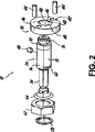
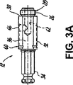
図1〜図4に示されるように、心軸10は軸方向に細長い心軸本体24を備えており、これは、心軸本体の端部に形成された第1のねじ山付き部26を含み、ホールカッタ12(図6)のねじ山付き孔16にねじ留め的に係合可能な主ねじ直径28を規定する。ショルダ又はストップ表面30が、第1のねじ山付き部26に隣接して、そこから放射状に外向きに間隔を空けて形成されている。第2のねじ山付き部32は、第1のねじ山付き部26に対してショルダ30の他の側面に、軸方向に間隔を空けられている。駆動柄34が、心軸本体12の他の端部に形成される。一対の第1のベアリング表面36が、お互いに対して心軸本体24の向かい合わせの側に形成され、ショルダ30と駆動柄34との間の心軸本体の実質的な部分に軸方向に沿って延在している。本発明の描かれている実施形態では、駆動柄34は、関連分野の当業者には既知のタイプのクイックリリースパワー駆動柄である。しかし、ここの教示に基づいて関連分野の当業者に認識され得るように、柄34は、ここで開示されている柄34の機能を実行するために現時点で知られているか又は後に知られるようになる数多くの異なるタイプの柄又はその他の構造のいずれかの形態を取り得る。
1-4, the
さらに、心軸10は、心軸本体24をスライド可能に受容するために、貫通して延在している開口部40を規定するピンリング38を含む。図4に最もよく示されているように、軸方向ベアリング表面42がピンリング38の片側に形成され、一対の駆動ピン44が開口部40に対して放射状に間隔を空けられて軸方向ベアリング表面42から軸方向に延在している。ピンリング38は更に、開口部40の向かい合わせの周辺部を形成する一対の第2のベアリング表面46を規定する。第2のベアリング表面46は、心軸本体24の対応する第1のベアリング表面36にスライド可能に係合して、心軸本体及びピンリングの相対的回転を防ぐ。
Further, the
一対の曲線状表面48が、お互いに対して開口部40の向かい合わせの側に形成され、対向する第2のベアリング表面46の端の間に延在している。曲線状表面48は、心軸本体の第2のねじ山付き部32のすぐ近くで間隔を空けられているが、それには接触しておらず、心軸本体の第2のねじ山付き部の上でのピンリングのスライド運動を許容する。見られるように、向かい合わせのベアリング表面46と曲線状表面48とは、「二重D」配置を形成する。しかし、ここの教示に基づいて関連分野の当業者によって認識されように、この配置は単なる例であり、現時点で知られているか又は後に知られるようになる数多くの他の形状及び/又は配置が等しく使用され得る。
A pair of
図1に示されているように、心軸本体24はピンリング38の開口部40の内部に受容され、図1に矢印50によって示されているように、ピンリング及心軸本体はお互いに対して軸方向に移動可能である。しかし、第1及び第2のベアリング表面36及び46はそれぞれ、お互いに対してスライド可能に係合して、ピンリング及び心軸本体がお互いに対して回転することを防ぐ。図5及び図6に示されているように、ピンリング38の駆動ピン44は、ホールカッタ12の対応するピン孔18内に受容可能である。ピンリング38の軸方向ベアリング表面42及び第2のベアリング表面46の前進方向のエッジは、心軸本体24のショルダ30上を軸方向に移動可能で、心軸本体の第1のねじ山付き部26の主直径28に係合可能である。結果として、及び以下に更に記述されるように、ピンリング38の軸方向ベアリング表面42は、ホールカッタ12の端壁14に突合せ的に係合可能で、ピンリング38の駆動ピン44がホールカッタの対応するピン孔18内に受容される。
As shown in FIG. 1, the
図1に示されているように、心軸10は更に、心軸本体24の第2のねじ山付き部32にねじ留め的に係合可能で、ピンリング38の軸方向ベアリング表面42をホールカッタ12に突合せ的係合状態で開放可能に固定するロック部材52を含む。弾性部材54は、ロック部材52とピンリング38との間の心軸本体24に受容可能で、ロック部材及びピンリングのホールカッタへの固定を容易にする。本発明の描かれている実施形態では、ロック部材52はねじ山付きナットの形態であり、弾性部材54はエラストマOリングの形態である。弾性部材54は、ロック部材52が手で締め付けられて、ピンリングをホールカッタに突合せ係合状態で開放可能に、しかし、しっかりと固定でき、且つ引き続いてロック部材を手で開放できることを容易にする。したがって、弾性部材54は、望まれるならば、工具なしの「クイックチェンジ」心軸を可能にする。しかし、ここの教示に基づいて関連分野の当業者によって認識されように、ここで描かれている特定のロック部材及び弾性部材は例にすぎず、数多くの異なるタイプの留め具のような数多くの他のタイプのロック部材、及び数多くの他のタイプの弾性部材、又はこれらの構成要素の一方又は両方の機能を実行するために現時点で知られているか又は後に知られるようになる、ロック部材をロックされた位置に維持することを容易にするための他のタイプの構造のいずれかが、等しく使用され得る。
As shown in FIG. 1, the
望まれるならば、図4に破線で示されているように、各々の第2のベアリング表面46は、心軸本体24の第1のねじ山付き部26に係合可能な面取りエッジ56を規定し得る。
If desired, each
さらに、心軸10は、第2のねじ山付き部32の一端で心軸本体24に形成された溝60(図2)に、例えば接続可能な保持クリップ58を備え、ロック部材52を係合し、且つその更なる軸方向の動きを防ぐ。描かれている実施形態では、クリップ58はcクリップであるが、ここの教示に基づいて関連分野の当業者によって認識されように、保持クリップは、数多くの異なるタイプのクリップ、留め具、又はここで開示されている保持クリップの機能を実行するために現時点で知られているか、又は後に知られるようになる他の構造のいずれかが、等しく使用され得る。
Further, the
さらに、図3に示されているように、心軸本体24は、心軸本体の第1のねじ山付き部26に対して内側に放射状に間隔を空けられてパイロットドリル64(図5及び図6)を受容するパイロットドリル開口部62と、心軸本体の側壁を通って放射状に延在している留め具開口部66とを規定する。さらに、図1に示されているように、心軸10は、留め具開口部66内に受容可能で、且つパイロットドリル開口部62内に受容されたパイロットドリル64と係合可能な留め具68を含み、パイロットドリルを心軸本体にしっかりと固定する。ピンリング38は、留め具開口部66内に受容された留め具68に対して、軸方向に移動可能である。描かれている実施形態では、留め具68はセットねじであるが、ここの教示に基づいて関連分野の当業者によって認識されように、留め具は、ここで開示されている留め具の機能を実行するために現時点で知られているか又は後に知られるようになる数多くの異なるタイプの留め具のいずれかが、等しく使用され得る。
Further, as shown in FIG. 3, the
心軸10の動作において、心軸本体24の第1のねじ山付き部26は、ホールカッタの端壁14が心軸本体のストップ表面30に接触するまで、ホールカッタ12のねじ山付き孔16にねじ留め的に接続される。それから、心軸本体24の第1のねじ山付き部26は、ホールカッタ12の対応するピン孔18と位置合わせさせるためにちょうど十分なように、又はピンリング38の駆動ピン44がそれに位置合わせされるまで、ホールカッタ12のねじ山付き孔16からねじ留めを緩められるか、又は「後退」される。ピンリング38はそれから、心軸本体24上を軸方向にホールカッタ12に向かって、ピンリング38の駆動ピン44がホールカッタ12のピン孔18内に受容されてピンリング38の軸方向ベアリング表面42がホールカッタの端壁14に突合せ的に係合するまで、動かされる。それから、ロック部材52が回転されて、心軸本体24上を軸方向にピン支持部材38に向かって動き、弾性部材54に対して締め付けられて、ピンリングの軸方向ベアリング表面42をホールソー12の端壁14に突合せ係合状態で開放可能に、しかし、しっかりと固定する。
In operation of the
図5及び図6に示されているように、パイロットドリル64は、上述された方法で心軸本体24にしっかりと固定され、スラグ開放ばね70がパイロットドリルのベースに搭載されて、心軸本体のねじ山付き部26に開放可能に固定され、ワークピースのスクラップ及び/又はスラグをホールカッタから開放することを容易にする。
As shown in FIGS. 5 and 6, the
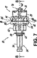
図7及び図8に示されているように、心軸10は数多くの異なるタイプ及び/又はサイズのホールカッタのいずれかと共に使用可能である。わかるように、図7及び図8に示されているホールカッタ12は、図5及び図6に描かれているホールカッタよりも小さなカット直径を有している。しかし、端壁14に同じ孔パターンがあるそのような異なるサイズのホールカッタを設けることによって、それらは各々、同じ心軸10と共に使用可能である。
As shown in FIGS. 7 and 8, the
本発明の一つの効果は、ピンリングの軸方向ベアリング表面42と第2のベアリング表面46のエッジとが心軸本体のストップ表面30上を軸方向に移動可能であり、且つ心軸本体の第1のねじ山付き部26の主直径28と係合可能であるので、ピンリングの軸方向ベアリング表面42が、ホールカッタ12の端壁14にロック位置で突合せ的に係合することができることである。結果として、従来技術の心軸が遭遇するピンリングとホールカッタの端壁との間に形成されるギャップが無くされ、本発明の心軸は、実質的に軸外れぶれ無しに動作することができる。さらに、本発明の他の効果は、心軸が、心軸の軸方向ベアリング表面とホールカッタの端壁との間のあらゆるキャップを、従来技術の心軸に比較して、より少ない部品及び比較的単純で、且つ使いやすい構成で、無くすことができる点である。
One advantage of the present invention is that the
ここの教示に基づいて関連分野の当業者によって認識されように、数多くの変更及び改変が、添付の請求項に規定されているような本発明から逸脱することなく、本発明の上述の及びその他の実施形態に対してなされ得る。例えば、心軸の構成要素は、現時点で既知であるか又は後に知られるようになる数多くの異なる材料のいずれかから形成され得て、且つ心軸は、現時点で既知であるか又は後に知られるようになる数多くの異なるタイプのツールのいずれかと共に使用され得る。したがって、現時点で好適な実施形態のこの詳細な記述は、限定的な意味とは反対に、描写的な意味で取られるべきである。 Numerous changes and modifications will become apparent to those skilled in the relevant art based on the teachings herein, and numerous changes and modifications may be made to the above and other aspects of the invention without departing from the invention as defined in the appended claims. Can be made to this embodiment. For example, the components of the mandrel can be formed from any of a number of different materials that are currently known or later become known and the mandrel is now known or later known Can be used with any of a number of different types of tools. Accordingly, this detailed description of the presently preferred embodiments should be taken in a descriptive sense, as opposed to a limiting sense.
Claims (19)
前記ホールカッタの前記ねじ山付き孔にねじ留め的に係合可能な第1のねじ山付き部と、前記第1のねじ山付き部に隣接して形成され且つ前記第1のねじ山付き部から軸方向に間隔を空けて設けられ、放射状に外向きに形成されたストップ表面と、前記心軸本体の他の端部に位置する駆動柄と、前記ストップ表面と駆動柄との間の前記心軸本体の部分に沿って軸方向に延在している第1のベアリング表面と、を含む心軸本体と、
貫通して形成された開口部を含むピン支持部材であって、ピン支持部材の片側に形成された軸方向ベアリング表面と、前記軸方向ベアリング表面の外側に向かって延在している少なくとも一つのピンと、前記開口部の内壁に形成された第2のベアリング表面と、を含み、前記心軸本体は前記ピン支持部材の前記開口部内部に受容可能であり、前記ピン支持部材と心軸本体との少なくとも一つが他方に対して軸方向に運動可能であり、前記第1のベアリング表面と第2のベアリング表面とが互いに係合可能で前記ピン支持部材及び心軸本体の相対的回転を防ぎ、前記少なくとも一つのピンが前記ホールカッタの前記少なくとも一つのピン孔の内部に受容可能であり、前記軸方向ベアリング表面と第2のベアリング表面とが交差するエッジが前記心軸本体の前記ストップ表面の外周を軸方向に移動可能で、前記心軸本体の前記第1のねじ山付き部の周面に係合可能であり、それによって前記心軸本体に対する前記第1のねじ山付き部側へ向けての更なる軸方向の動きを防ぎ、前記ピン支持部材の前記軸方向ベアリング表面が前記ホールカッタに突合せ的に係合可能で前記少なくとも一つのピンが前記ホールカッタの前記少なくとも一つの対応するピン孔内に受容される、ピン支持部材と、
前記心軸本体に係合可能で、前記ピン支持部材を前記ホールソーに開放可能に固定するロック部材と、
を備える、心軸。A mandrel for a hole cutter comprising an outer surface defining a threaded hole and at least one pin hole radially spaced from the threaded hole,
Said threaded hole in the screw to part comes first threaded mountain engageable in the hole cutter, the first formed adjacent to the threaded portion and the first with thread A stop surface provided in an axial direction from the portion and formed radially outward, a drive handle located at the other end of the mandrel body, and between the stop surface and the drive handle A first bearing surface extending in an axial direction along a portion of the mandrel body;
A pin support member including an opening formed therethrough, the axial bearing surface formed on one side of the pin support member, and at least one extending toward the outside of the axial bearing surface a pin, and a second bearing surface formed on the inner wall of the opening, only contains the arbor body is receivable within said opening of said pin supporting member, said pin support member and arbor body And the first bearing surface and the second bearing surface are engageable with each other to prevent relative rotation of the pin support member and the mandrel body. said at least one pin is receivable within said at least one pin hole of the hole cutter, edge and said axial bearing surface and a second bearing surface intersects said Movable outer periphery of said stop surfaces of the shaft body in the axial direction, the mandrel can engage the peripheral surface of the first threaded out portion of the main body, the first relative to the arbor body thereby Further axial movement toward the threaded portion side of the pin support member, the axial bearing surface of the pin support member is abuttably engageable with the hole cutter, and the at least one pin is the hole cutter. A pin support member received in the at least one corresponding pin hole of
A locking member that is engageable with the mandrel body and that releasably fixes the pin support member to the hole saw;
With a mandrel.
前記方法は、
前記ホールカッタが前記心軸本体の前記ストップ表面に接触するまで前記心軸本体の前記第1のねじ山付き部を前記ホールカッタの前記ねじ山付き孔にねじ留め的に接続するステップと、
前記心軸本体の前記第1のねじ山付き部を前記ホールカッタの前記ねじ山付き孔から緩めて、前記ピン支持部材の前記少なくとも一つのピンを前記ホールカッタの前記少なくとも一つの対応するピン孔に位置合わせするステップと、
前記ピン支持部材と前記軸方向ベアリング表面を貫通して外に向かって延在している前記少なくとも一つのピンとを、前記心軸本体の上を軸方向に前記ホールカッタに向かって、前記少なくとも一つのピンが前記ホールカッタの前記少なくとも一つの対応するピン孔内に受容され前記少なくとも一つのピンに隣接した前記軸方向ベアリング表面の前記一部を含む前記軸方向ベアリング表面が前記ホールカッタに突合せ的に係合するまで動かすステップと、
前記ロック部材を、前記心軸本体上を軸方向に前記ピン支持部材に向かって動かし、且つ前記少なくとも一つのピンに隣接した前記軸方向ベアリング表面の前記一部を含む前記ピン支持部材の前記軸方向ベアリング表面を、前記ロック部材にて、前記ホールカッタに突合せ係合状態で開放可能に固定するステップと、
を包含する、方法。A method of attaching a mandrel to a hole cutter, the hole cutter comprising an outer surface defining a threaded hole and at least one drive pin hole radially spaced from the threaded hole. with which the mandrel is spaced a first threaded out portions, apart axially from the first formed adjacent to the portion comes threaded mountain and the first threaded portion provided Te, and mandrel body including a outwardly formed stop surface radially, a pin support member including an aperture formed therethrough, the axial direction formed on one side of the pin support member At least one pin extending through and outwardly through the bearing surface and the axial bearing surface, the at least one pin being adjacent to a portion of the axial bearing surface and the opening formed on the inner wall of the Look including a second bearing surface which, said axial bearing surface and the said second edge of the second bearing surface intersects the movable outer periphery of the stop surface of the arbor body in the axial direction includes a pin support member is engageable to the unit can with 1 thread, a locking member coupled to the arbor body, and
The method
Screwing the first threaded portion of the mandrel body into the threaded hole of the hole cutter until the hole cutter contacts the stop surface of the mandrel body;
Loosening the first threaded portion of the mandrel body from the threaded hole of the hole cutter and moving the at least one pin of the pin support member to the at least one corresponding pin hole of the hole cutter To align with,
The pin support member and the at least one pin that extends outwardly through the axial bearing surface are arranged on the mandrel body axially toward the hole cutter in the axial direction. An axial bearing surface is received in the at least one corresponding pin hole of the hole cutter and the axial bearing surface including the portion of the axial bearing surface adjacent to the at least one pin is abutting the hole cutter. Moving until it engages,
The axis of said pin support member and said locking member comprises said portion of said upper arbor body move toward the pin support member in the axial direction, and the said axial bearing surface adjacent to at least one pin comprising the steps of a direction bearing surfaces at the locking member is releasably secured in abutting engagement with the hole cutter,
Including the method.
前記心軸本体の外周に位置する弾性部材を、前記ピン支持部材と前記ロック部材との間に設けるステップを更に包含する請求項16に記載の方法。 The pin support member is moved until the axial bearing surface is abuttingly engaged with the hole cutter, and the axial bearing surface can be released in abutting engagement with the hole cutter by the lock member. Between the step of fixing to
The method according elastic member located on an outer periphery of the arbor Body, further comprising Claim 16 steps of providing between the locking member and the pin support member.
Applications Claiming Priority (3)
| Application Number | Priority Date | Filing Date | Title |
|---|---|---|---|
| US48217003P | 2003-06-24 | 2003-06-24 | |
| US10/875,092 US7073992B2 (en) | 2003-06-24 | 2004-06-23 | Arbor for hole cutter and related method of use |
| PCT/US2004/020402 WO2005002310A2 (en) | 2003-06-24 | 2004-06-24 | Arbor for hole cutter and related method of use |
Publications (3)
| Publication Number | Publication Date |
|---|---|
| JP2007521146A JP2007521146A (en) | 2007-08-02 |
| JP2007521146A5 JP2007521146A5 (en) | 2009-06-25 |
| JP4481985B2 true JP4481985B2 (en) | 2010-06-16 |
Family
ID=34107673
Family Applications (1)
| Application Number | Title | Priority Date | Filing Date |
|---|---|---|---|
| JP2006517656A Expired - Lifetime JP4481985B2 (en) | 2003-06-24 | 2004-06-24 | Mandrel for hole cutters and related uses |
Country Status (9)
| Country | Link |
|---|---|
| US (1) | US7073992B2 (en) |
| EP (1) | EP1638721B1 (en) |
| JP (1) | JP4481985B2 (en) |
| KR (1) | KR100658112B1 (en) |
| AU (1) | AU2004253518B2 (en) |
| BR (1) | BRPI0411918B1 (en) |
| CA (1) | CA2531164C (en) |
| MX (1) | MXPA05014206A (en) |
| WO (1) | WO2005002310A2 (en) |
Families Citing this family (44)
| Publication number | Priority date | Publication date | Assignee | Title |
|---|---|---|---|---|
| ES2290561T3 (en) * | 2003-12-15 | 2008-02-16 | Synthes Gmbh | COUPLING DEVICE. |
| US7621703B2 (en) * | 2004-06-08 | 2009-11-24 | Kym John Keightley | Hole saw assembly |
| DE102004042735A1 (en) * | 2004-09-03 | 2006-03-09 | Robert Bosch Gmbh | Tool holder, adapter and system with a tool holder and an adapter |
| AU304054S (en) * | 2005-06-03 | 2005-11-10 | Holesaw arbour | |
| US9022703B2 (en) | 2005-06-08 | 2015-05-05 | Kym John Keightley | Hole saw assembly |
| TWI400758B (en) * | 2005-12-28 | 2013-07-01 | 半導體能源研究所股份有限公司 | Semiconductor device manufacturing method |
| US7824137B2 (en) * | 2006-05-17 | 2010-11-02 | Maxtech Consumer Products Limited | Universal quick connect system for a hole saw |
| US7802948B1 (en) * | 2006-06-07 | 2010-09-28 | Matthew R Bastiaans | Drill extender |
| US20080014035A1 (en) * | 2006-06-30 | 2008-01-17 | Noveon Ip Holdings Corp. | Clamping Tool And Hole Saw Apparatus |
| US7674078B1 (en) * | 2006-07-28 | 2010-03-09 | Mirko Buzdum | Hole saw having efficient slug removal |
| US7517179B2 (en) * | 2006-11-16 | 2009-04-14 | Black & Decker Inc. | Small holesaw mandrel assembly |
| US7488146B2 (en) * | 2006-11-16 | 2009-02-10 | Black & Decker Inc. | Large holesaw mandrel assembly |
| US20080181740A1 (en) * | 2007-01-29 | 2008-07-31 | Waitszies Roland G | Drill bit extension |
| US8038371B2 (en) * | 2007-04-13 | 2011-10-18 | Black & Decker Inc. | Push button holesaw mandrel assembly |
| US8038372B2 (en) | 2007-04-13 | 2011-10-18 | Black & Decker Inc. | Push button holesaw mandrel assembly |
| US20080267725A1 (en) * | 2007-04-30 | 2008-10-30 | Stanley Luke Mills | High Speed Industrial Hole Saw for Production Line Applications |
| DE102007022186A1 (en) * | 2007-05-11 | 2008-11-13 | Robert Bosch Gmbh | Adapter for operating a hole saw on a drive machine |
| TWM340163U (en) * | 2008-02-22 | 2008-09-11 | K & W Tools Co Ltd | Hole-drilling saw |
| USRE46103E1 (en) | 2008-03-06 | 2016-08-16 | Irwin Industrial Tool Company | Quick change arbor, hole cutter, and method |
| US8328474B2 (en) * | 2008-03-06 | 2012-12-11 | Irwin Industrial Tool Company | Quick change arbor, hole cutter, and method |
| US8366356B2 (en) | 2008-03-06 | 2013-02-05 | Irwin Industrial Tool Company | Quick change arbor, hole cutter, and method |
| AU2013200602B2 (en) * | 2008-03-18 | 2015-04-30 | Black & Decker Inc. | Quick change arbor, hole cutter, and method |
| US8328476B2 (en) * | 2008-03-18 | 2012-12-11 | Irwin Industrial Tool Company | Quick change arbor, hole cutter, and method |
| US8360696B2 (en) * | 2008-03-18 | 2013-01-29 | Irwin Industrial Tool Company | Quick change arbor, hole cutter, and method |
| US8434976B2 (en) * | 2009-03-20 | 2013-05-07 | Black & Decker Inc. | Small hole saw mandrel assembly |
| US9434033B2 (en) * | 2010-01-13 | 2016-09-06 | Irwin Industrial Tool Company | Hole cutter with extruded cap |
| CA2787071A1 (en) * | 2010-01-14 | 2011-07-21 | Wilbur Keith Moffatt | Locking hole saw collar |
| CN102476222B (en) * | 2010-11-24 | 2014-12-10 | 南京德朔实业有限公司 | Tapper used for oscillation tool |
| US9849553B2 (en) * | 2013-03-12 | 2017-12-26 | Christopher R. Bialy | Drilling safety system |
| US9248514B2 (en) * | 2013-09-10 | 2016-02-02 | Textron Innovations Inc. | Arbor assembly for use with a cutting device, such as a cutter or hole saw |
| USD748701S1 (en) * | 2013-11-27 | 2016-02-02 | Nir Velozny | Inner ring of a construction drilling cup |
| USD748170S1 (en) * | 2013-11-27 | 2016-01-26 | Nir Velozny | Connector for construction drilling cup |
| USD748700S1 (en) * | 2013-11-27 | 2016-02-02 | Nir Velozny | Construction drilling cup |
| USD748702S1 (en) * | 2013-11-27 | 2016-02-02 | Nir Velozny | Accessory for inner ring of drilling cup and for housing of electrical appliances |
| GB201514377D0 (en) * | 2015-08-13 | 2015-09-30 | Ward Derek A And Katz Marc S | Hole-saw |
| US10799959B2 (en) | 2017-02-24 | 2020-10-13 | Milwaukee Electric Tool Corporation | Rotary power tool including threaded bit attachment |
| CN108284490A (en) * | 2018-01-19 | 2018-07-17 | 杭州萧山强森工具有限公司 | A kind of quick-release connector of drilling tool |
| USD882650S1 (en) * | 2019-08-16 | 2020-04-28 | Ali Industries, Inc. | Hex driver drum sander |
| USD1049803S1 (en) * | 2020-10-26 | 2024-11-05 | Kody J. Ketterling | Driver for rotary sod cutting tool |
| CN112276153A (en) * | 2020-10-30 | 2021-01-29 | 中国航发南方工业有限公司 | Method for processing multi-level hole site for precision device |
| US11872642B2 (en) | 2021-11-12 | 2024-01-16 | Robert James Suhling | Dynamicaly configurable arbor assembly apparatus |
| US20240100609A1 (en) | 2022-09-23 | 2024-03-28 | Black & Decker Inc. | Holesaw system |
| CN115815679B (en) * | 2022-11-16 | 2024-11-19 | 苏州中航盛世刀辊制造有限公司 | A pressurizing mechanism for preventing knife jumping |
| CN120286742B (en) * | 2025-06-10 | 2025-09-09 | 常德市中凯机械工业有限公司 | Flange opening device |
Family Cites Families (61)
| Publication number | Priority date | Publication date | Assignee | Title |
|---|---|---|---|---|
| US2779361A (en) | 1954-03-17 | 1957-01-29 | Miller Mfg Corp | Sawing tool for cutting circular holes |
| US3390596A (en) * | 1965-09-01 | 1968-07-02 | Trevathan Sales Corp | Cutting head assembly |
| US3758221A (en) | 1971-12-29 | 1973-09-11 | Black & Decker Mfg Co | Hole saw assembly |
| US3784316A (en) | 1972-07-12 | 1974-01-08 | Capewell Mfg Co | Hole saw and reversible quick disconnect drive therefor |
| US3837759A (en) | 1972-07-12 | 1974-09-24 | Capewell Mfg Co | Hole saw and quick disconnect drive therefor |
| DE2249234A1 (en) | 1972-10-07 | 1974-04-18 | Bosch Gmbh Robert | QUICK CHANGE TOOL ADAPTER |
| US3880546A (en) | 1974-03-13 | 1975-04-29 | Segal F | Hole saw assembly |
| US3973862A (en) | 1975-06-02 | 1976-08-10 | Segal F | Pilot drill locating means for hole saw assembly |
| US4036560A (en) | 1975-11-03 | 1977-07-19 | Stanadyne, Inc. | Heavy duty hole saw and arbor assembly |
| DE7536182U (en) | 1975-11-14 | 1978-02-02 | Robert Bosch Gmbh, 7000 Stuttgart | DEVICE FOR TORQUE TRANSMISSION |
| DE2602238A1 (en) | 1976-01-22 | 1977-08-04 | Bosch Gmbh Robert | DRILL BIT |
| US4148593A (en) | 1978-01-27 | 1979-04-10 | Stanadyne, Inc. | Hole saw assembly |
| DE2808253C2 (en) | 1978-02-25 | 1986-06-12 | Robert Bosch Gmbh, 7000 Stuttgart | Drill chuck |
| DE2811328C2 (en) | 1978-03-16 | 1986-09-25 | Robert Bosch Gmbh, 7000 Stuttgart | Drill chuck |
| DE2851161A1 (en) | 1978-11-25 | 1980-06-12 | Bosch Gmbh Robert | LINING FOR HAND MACHINE TOOLS, IN PARTICULAR SPROCKET DRILLING CHUCK |
| DE2937603C2 (en) | 1979-09-18 | 1986-09-25 | Robert Bosch Gmbh, 7000 Stuttgart | Chucks for machine tools, in particular drilling machines |
| DE2943500A1 (en) | 1979-10-27 | 1981-05-07 | Robert Bosch Gmbh, 7000 Stuttgart | TOOL CLAMP |
| US4303357A (en) | 1980-05-19 | 1981-12-01 | William Makar | Quick-change hole saw mandrel |
| JPS5821989A (en) * | 1981-07-31 | 1983-02-09 | Canon Inc | Color solid-state image pickup device |
| US4491443A (en) | 1982-10-29 | 1985-01-01 | Textron Inc. | Modified quick release adapter |
| US4626152A (en) | 1985-04-08 | 1986-12-02 | Milwaukee Electric Tool Corporation | Quick change tool retainer |
| US4669928A (en) | 1986-10-07 | 1987-06-02 | Eugenio Mediavilla | Hole saw mandrel |
| DE3841181A1 (en) | 1988-12-07 | 1990-06-13 | Bosch Gmbh Robert | HAND MACHINE TOOL WITH A MULTI-PIECE MANUAL QUICK-RELEASE DEVICE |
| DE4005757A1 (en) | 1990-02-23 | 1991-08-29 | Bosch Gmbh Robert | Hand-tool machine with drill chuck - incorporates locking device preventing loosening of chuck jaws during operation |
| US5061126A (en) | 1990-05-04 | 1991-10-29 | Rule Industries | Hole saw and mandrel assembly |
| JPH0747244B2 (en) | 1991-02-19 | 1995-05-24 | 株式会社ミヤナガ | Core drill |
| US5074722A (en) | 1991-03-15 | 1991-12-24 | Greenlee Textron Inc. | Hole cutter |
| US5108235A (en) | 1991-05-14 | 1992-04-28 | Greenlee Textron Inc. | Hole saw arbor |
| GB2257381A (en) * | 1991-07-09 | 1993-01-13 | Eldon Tool Company Limited | Arbor for hole saw. |
| US5154552A (en) | 1991-12-31 | 1992-10-13 | American Saw & Mfg. Company | Quick-release arbor for hole saws |
| US5246317A (en) | 1991-12-31 | 1993-09-21 | American Saw & Mfg. Company | Quick-release arbor for hole saws |
| US5226762A (en) | 1992-08-06 | 1993-07-13 | Ecker Robert J | Sealed hole-saw arbor |
| DE4307780A1 (en) | 1993-03-12 | 1994-09-15 | Bosch Gmbh Robert | Drill chuck |
| US5352071A (en) | 1993-06-07 | 1994-10-04 | Greenlee Textron Inc. | Hole saw arbor with retaining mechanism |
| AU670373B2 (en) | 1993-06-30 | 1996-07-11 | Nitto Kohki Co., Ltd. | Annular cutter connecting apparatus and annular cutter |
| GB9423388D0 (en) * | 1994-11-19 | 1995-01-11 | Eldon Eng Comp Ltd | Holesaw assembly |
| US5967709A (en) | 1995-01-31 | 1999-10-19 | Thuesen; Jorgen | Adaptor for rotating tools |
| DE19521993B4 (en) | 1995-06-20 | 2009-04-09 | Robert Bosch Gmbh | Tool holder and tool for a drilling and / or percussion machine tool |
| US5597274A (en) * | 1995-08-17 | 1997-01-28 | Behner; Ray E. | Hole cutter |
| US5658102A (en) | 1995-09-12 | 1997-08-19 | The L. S. Starrett Company | Hole saw arbor method and apparatus |
| SE509754C2 (en) * | 1995-10-27 | 1999-03-01 | Sandvik Ab | Hole saw |
| US5813802A (en) | 1995-11-30 | 1998-09-29 | House B.M. Co., Ltd. | Drilling tool assembly and its center drill and cup shape drill |
| DE19604282A1 (en) | 1996-02-07 | 1997-08-14 | Bosch Gmbh Robert | Tool holder with holder for various tool systems |
| AU717372B2 (en) | 1996-09-13 | 2000-03-23 | Vancouver Gear Works Ltd. | Saw arbor with splined mandrel and mating, timed internally and externally splined saw blade mounting sleeve |
| SE510841C2 (en) * | 1996-12-19 | 1999-06-28 | Sandvik Ab | Hole saw |
| EP1016480B1 (en) | 1997-02-28 | 2004-09-01 | Kabushiki Kaisha Miyanaga | Shank fitting structure |
| US5868532A (en) | 1997-03-24 | 1999-02-09 | American Saw & Mfg. Company | Arbor for engaging a saw |
| DE19755727C1 (en) | 1997-12-15 | 1999-01-21 | Bosch Gmbh Robert | Quick change format head for container handing machine |
| DE19827172B4 (en) | 1998-06-18 | 2006-11-09 | Robert Bosch Gmbh | Tool holders, in particular for drills or impact hammers |
| TW422149U (en) | 1999-06-28 | 2001-02-11 | K & W Tools Co Ltd | Connecting device for hole-drilling saw |
| EP1066902A3 (en) | 1999-06-30 | 2002-10-09 | Nicotec Co., Ltd. | Separation type hole saw |
| US6705807B1 (en) | 1999-11-24 | 2004-03-16 | Black & Decker Inc. | Hole saw and connection method |
| US6494401B2 (en) | 2000-01-27 | 2002-12-17 | Franklin C. Bradshaw | Arbor for securing reels on a shaft |
| DE10005910B4 (en) | 2000-02-10 | 2005-10-13 | Robert Bosch Gmbh | Hand tool with a replaceable tool holder |
| DE10017980A1 (en) | 2000-04-11 | 2001-10-25 | Bosch Gmbh Robert | Machine tool holder |
| DE60131108T2 (en) | 2000-09-01 | 2008-08-07 | Credo Technology Corp., Wilmington | Quick release spindle unit for hole saw and drill |
| GB0026051D0 (en) | 2000-10-25 | 2000-12-13 | Universal Drilling And Cutting | Arbor |
| US20020122703A1 (en) | 2001-02-16 | 2002-09-05 | Peter Czyzewski | Quick change adaptor for hole saw |
| AUPR780301A0 (en) | 2001-09-21 | 2001-10-11 | Keightley, Kym | Improved hole saw |
| SE0202326L (en) * | 2002-07-26 | 2004-01-27 | Gsm Ind Ab | Shaft for hole saw |
| US6939092B2 (en) | 2003-06-18 | 2005-09-06 | Irwin Industrial Tool Company | Sheet metal hole cutter |
-
2004
- 2004-06-23 US US10/875,092 patent/US7073992B2/en not_active Expired - Lifetime
- 2004-06-24 JP JP2006517656A patent/JP4481985B2/en not_active Expired - Lifetime
- 2004-06-24 AU AU2004253518A patent/AU2004253518B2/en not_active Ceased
- 2004-06-24 WO PCT/US2004/020402 patent/WO2005002310A2/en not_active Ceased
- 2004-06-24 MX MXPA05014206A patent/MXPA05014206A/en not_active Application Discontinuation
- 2004-06-24 KR KR1020057024859A patent/KR100658112B1/en not_active Expired - Fee Related
- 2004-06-24 EP EP04756093.3A patent/EP1638721B1/en not_active Expired - Lifetime
- 2004-06-24 CA CA2531164A patent/CA2531164C/en not_active Expired - Fee Related
- 2004-06-24 BR BRPI0411918-5A patent/BRPI0411918B1/en not_active IP Right Cessation
Also Published As
| Publication number | Publication date |
|---|---|
| EP1638721B1 (en) | 2019-02-20 |
| WO2005002310A3 (en) | 2005-05-26 |
| BRPI0411918B1 (en) | 2014-09-16 |
| WO2005002310A8 (en) | 2005-03-17 |
| KR100658112B1 (en) | 2006-12-14 |
| US7073992B2 (en) | 2006-07-11 |
| US20050025591A1 (en) | 2005-02-03 |
| CA2531164C (en) | 2012-09-11 |
| JP2007521146A (en) | 2007-08-02 |
| BRPI0411918A (en) | 2006-08-15 |
| CA2531164A1 (en) | 2005-01-13 |
| AU2004253518A1 (en) | 2005-01-13 |
| KR20060064574A (en) | 2006-06-13 |
| WO2005002310A2 (en) | 2005-01-13 |
| EP1638721A4 (en) | 2010-05-26 |
| AU2004253518B2 (en) | 2007-03-15 |
| MXPA05014206A (en) | 2006-08-11 |
| EP1638721A2 (en) | 2006-03-29 |
Similar Documents
| Publication | Publication Date | Title |
|---|---|---|
| JP4481985B2 (en) | Mandrel for hole cutters and related uses | |
| EP2252421B1 (en) | Quick change hole cutter and arbor | |
| US8366356B2 (en) | Quick change arbor, hole cutter, and method | |
| US8328476B2 (en) | Quick change arbor, hole cutter, and method | |
| US20020122703A1 (en) | Quick change adaptor for hole saw | |
| JP2007521146A5 (en) | ||
| EP2289656A1 (en) | Adjustable depth hole saw assembly | |
| CN102006960B (en) | Quick-change tool shaft, hole cutter and method | |
| CA2485935C (en) | Arbor apparatus for rotary tools |
Legal Events
| Date | Code | Title | Description |
|---|---|---|---|
| A131 | Notification of reasons for refusal |
Free format text: JAPANESE INTERMEDIATE CODE: A131 Effective date: 20090106 |
|
| A601 | Written request for extension of time |
Free format text: JAPANESE INTERMEDIATE CODE: A601 Effective date: 20090403 |
|
| A602 | Written permission of extension of time |
Free format text: JAPANESE INTERMEDIATE CODE: A602 Effective date: 20090410 |
|
| A524 | Written submission of copy of amendment under article 19 pct |
Free format text: JAPANESE INTERMEDIATE CODE: A524 Effective date: 20090501 |
|
| TRDD | Decision of grant or rejection written | ||
| A01 | Written decision to grant a patent or to grant a registration (utility model) |
Free format text: JAPANESE INTERMEDIATE CODE: A01 Effective date: 20100216 |
|
| A01 | Written decision to grant a patent or to grant a registration (utility model) |
Free format text: JAPANESE INTERMEDIATE CODE: A01 |
|
| A61 | First payment of annual fees (during grant procedure) |
Free format text: JAPANESE INTERMEDIATE CODE: A61 Effective date: 20100318 |
|
| FPAY | Renewal fee payment (event date is renewal date of database) |
Free format text: PAYMENT UNTIL: 20130326 Year of fee payment: 3 |
|
| R150 | Certificate of patent or registration of utility model |
Ref document number: 4481985 Country of ref document: JP Free format text: JAPANESE INTERMEDIATE CODE: R150 Free format text: JAPANESE INTERMEDIATE CODE: R150 |
|
| FPAY | Renewal fee payment (event date is renewal date of database) |
Free format text: PAYMENT UNTIL: 20130326 Year of fee payment: 3 |
|
| FPAY | Renewal fee payment (event date is renewal date of database) |
Free format text: PAYMENT UNTIL: 20140326 Year of fee payment: 4 |
|
| R250 | Receipt of annual fees |
Free format text: JAPANESE INTERMEDIATE CODE: R250 |
|
| R250 | Receipt of annual fees |
Free format text: JAPANESE INTERMEDIATE CODE: R250 |
|
| R250 | Receipt of annual fees |
Free format text: JAPANESE INTERMEDIATE CODE: R250 |
|
| R250 | Receipt of annual fees |
Free format text: JAPANESE INTERMEDIATE CODE: R250 |
|
| R250 | Receipt of annual fees |
Free format text: JAPANESE INTERMEDIATE CODE: R250 |
|
| R250 | Receipt of annual fees |
Free format text: JAPANESE INTERMEDIATE CODE: R250 |
|
| R250 | Receipt of annual fees |
Free format text: JAPANESE INTERMEDIATE CODE: R250 |
|
| S111 | Request for change of ownership or part of ownership |
Free format text: JAPANESE INTERMEDIATE CODE: R313113 |
|
| R371 | Transfer withdrawn |
Free format text: JAPANESE INTERMEDIATE CODE: R371 |
|
| S111 | Request for change of ownership or part of ownership |
Free format text: JAPANESE INTERMEDIATE CODE: R313113 |
|
| R350 | Written notification of registration of transfer |
Free format text: JAPANESE INTERMEDIATE CODE: R350 |