EP2252421B1 - Quick change hole cutter and arbor - Google Patents
Quick change hole cutter and arbor Download PDFInfo
- Publication number
- EP2252421B1 EP2252421B1 EP09716790.2A EP09716790A EP2252421B1 EP 2252421 B1 EP2252421 B1 EP 2252421B1 EP 09716790 A EP09716790 A EP 09716790A EP 2252421 B1 EP2252421 B1 EP 2252421B1
- Authority
- EP
- European Patent Office
- Prior art keywords
- arbor
- hole cutter
- drive pin
- aperture
- hole
- Prior art date
- Legal status (The legal status is an assumption and is not a legal conclusion. Google has not performed a legal analysis and makes no representation as to the accuracy of the status listed.)
- Active
Links
- 230000008859 change Effects 0.000 title claims description 75
- 230000007246 mechanism Effects 0.000 description 39
- 230000004323 axial length Effects 0.000 description 14
- 230000007935 neutral effect Effects 0.000 description 14
- 230000008901 benefit Effects 0.000 description 11
- 238000000034 method Methods 0.000 description 5
- 238000003780 insertion Methods 0.000 description 4
- 230000037431 insertion Effects 0.000 description 4
- 230000000007 visual effect Effects 0.000 description 4
- 230000036346 tooth eruption Effects 0.000 description 3
- 238000005553 drilling Methods 0.000 description 2
- 210000003811 finger Anatomy 0.000 description 2
- 239000002184 metal Substances 0.000 description 2
- 230000002093 peripheral effect Effects 0.000 description 2
- 230000008569 process Effects 0.000 description 2
- 210000003813 thumb Anatomy 0.000 description 2
- 241000282472 Canis lupus familiaris Species 0.000 description 1
- 230000000712 assembly Effects 0.000 description 1
- 238000000429 assembly Methods 0.000 description 1
- 238000007373 indentation Methods 0.000 description 1
- 230000003993 interaction Effects 0.000 description 1
- 239000000463 material Substances 0.000 description 1
- 230000013011 mating Effects 0.000 description 1
- 230000004048 modification Effects 0.000 description 1
- 238000012986 modification Methods 0.000 description 1
- 230000000717 retained effect Effects 0.000 description 1
Images


Classifications
-
- B—PERFORMING OPERATIONS; TRANSPORTING
- B23—MACHINE TOOLS; METAL-WORKING NOT OTHERWISE PROVIDED FOR
- B23B—TURNING; BORING
- B23B51/00—Tools for drilling machines
- B23B51/04—Drills for trepanning
- B23B51/0473—Details about the connection between the driven shaft and the tubular cutting part; Arbors
-
- Y—GENERAL TAGGING OF NEW TECHNOLOGICAL DEVELOPMENTS; GENERAL TAGGING OF CROSS-SECTIONAL TECHNOLOGIES SPANNING OVER SEVERAL SECTIONS OF THE IPC; TECHNICAL SUBJECTS COVERED BY FORMER USPC CROSS-REFERENCE ART COLLECTIONS [XRACs] AND DIGESTS
- Y10—TECHNICAL SUBJECTS COVERED BY FORMER USPC
- Y10T—TECHNICAL SUBJECTS COVERED BY FORMER US CLASSIFICATION
- Y10T408/00—Cutting by use of rotating axially moving tool
- Y10T408/03—Processes
-
- Y—GENERAL TAGGING OF NEW TECHNOLOGICAL DEVELOPMENTS; GENERAL TAGGING OF CROSS-SECTIONAL TECHNOLOGIES SPANNING OVER SEVERAL SECTIONS OF THE IPC; TECHNICAL SUBJECTS COVERED BY FORMER USPC CROSS-REFERENCE ART COLLECTIONS [XRACs] AND DIGESTS
- Y10—TECHNICAL SUBJECTS COVERED BY FORMER USPC
- Y10T—TECHNICAL SUBJECTS COVERED BY FORMER US CLASSIFICATION
- Y10T408/00—Cutting by use of rotating axially moving tool
- Y10T408/89—Tool or Tool with support
- Y10T408/895—Having axial, core-receiving central portion
- Y10T408/8957—Having axial, core-receiving central portion and having stepped cutting edges
-
- Y—GENERAL TAGGING OF NEW TECHNOLOGICAL DEVELOPMENTS; GENERAL TAGGING OF CROSS-SECTIONAL TECHNOLOGIES SPANNING OVER SEVERAL SECTIONS OF THE IPC; TECHNICAL SUBJECTS COVERED BY FORMER USPC CROSS-REFERENCE ART COLLECTIONS [XRACs] AND DIGESTS
- Y10—TECHNICAL SUBJECTS COVERED BY FORMER USPC
- Y10T—TECHNICAL SUBJECTS COVERED BY FORMER US CLASSIFICATION
- Y10T408/00—Cutting by use of rotating axially moving tool
- Y10T408/94—Tool-support
- Y10T408/95—Tool-support with tool-retaining means
Definitions
- the present invention relates to a quick change hole cutter according to the preamble of claim 1 and to an arbor according to the preamble of claim 2.
- a typical arbor for a hole saw includes an arbor body with a threaded end portion that engages a corresponding threaded aperture in the end plate of the hole saw to secure the hole saw to the arbor.
- a pilot drill bit is receivable within the threaded end portion of the arbor body and extends through the center of the hole saw.
- the arbor further includes a drive pin plate that slidably mounts to the arbor body and has a pair of diametrically opposed drive pins that extend into corresponding drive pin holes formed in the end plate of the hole saw to rotatably drive the hole saw.
- a lock nut is threadedly mounted on the arbor body to prevent disengagement of the drive pins from the hole saw during use.
- the end plate of the hole saw is threaded onto the threaded end portion such that the hole saw is secured to the arbor body and the drive pin holes are in alignment with the corresponding drive pins of the drive pin plate. Then the lock nut is tightened until the drive pins are fully received by the drive pin holes to secure the arbor to the hole saw.
- the pilot bit the bit is inserted into the center hole and secured by tightening a fastener.
- Such proprietary arbor and pilot drill bit systems can fail at fully securing the bits inside the arbor and/or can allow the bits to loosen during use causing off-axis wobble, especially at high rotational speeds. Off-axis wobble can cause undesirable vibration of the pilot drill bit that can reduce the drilling life of the bit and/or create an unacceptable degree of inaccuracy during use.
- Known arbors and hole cutter assemblies are disclosed by WO2004/011179A1 , GB2295110A , US2005/0025591A1 , US2004/0154837A1 , US4148593A , US5108235A , US5076741A , US2005/0025592A1 and US2007/0160435A1 .
- the present invention is directed to an arbor having the features of claim 2 that is connectable to a quick change hole cutter having the features of claim 1, and in some embodiments of the present invention, also is connectable to a standard hole cutter.
- the hole cutter includes an end portion defining a first aperture, and at least one drive pin recess radially spaced relative to the first aperture.
- the arbor comprises an arbor body including a stop surface, and a hole cutter connecting portion extending axially from the stop surface and engageable within the first aperture of the hole cutter.
- a drive pin member defines a second aperture that receives therethrough the arbor body, and is configured to allow relative axial movement, but to prevent relative rotational movement, of the arbor body and drive pin member.
- the drive pin member further includes a first surface, and at least one drive pin radially spaced relative to the second aperture and extending axially from the first surface.
- the connecting portion is receivable within the first aperture of the hole cutter to define a first engagement position.
- the arbor body and/or the hole cutter is movable relative to the other between the first engagement position and a second engagement position to secure the hole cutter to the arbor body.
- the at least one drive pin is substantially aligned with the at least one corresponding drive pin recess of the hole cutter; and (ii) the drive pin member is movable axially relative to the arbor body between a disengaged position axially spaced relative to the hole cutter, and an engaged position wherein the at least one drive pin is received within the corresponding drive pin recess of the hole cutter, and the first surface of the drive pin member contacts the end portion of the hole cutter.
- the end portion of the hole cutter is in contact with the stop surface of the arbor body.
- the arbor body and/or hole cutter is rotatable relative to the other between the first and second engagement positions.
- the connecting portion of the arbor body defines a first thread
- the first aperture of the hole cutter defines a second thread that is threadedly engageable with the first thread, to fixedly secure the hole cutter to the arbor body in the second engagement position.
- the threads on the connecting portion of the arbor body are configured to both (i) substantially align the at least one drive pin with the corresponding drive pin recess of the hole cutter in the second engagement position, and (ii) place the end portion of the hole cutter in contact with the stop surface of the arbor body in the second engagement position.
- the first and second threads define an axial clearance therebetween allowing the end portion of the hole cutter to substantially contact the stop surface of the arbor body in the both the first engagement position and the second engagement position.
- the arbor body and/or hole cutter is rotatable relative to the other between the first and second engagement positions, and the angular extent between the first and second engagement positions is within the range of about 10° and about 180°.
- the first aperture of the quick change hole cutter defines a plurality of angularly extending protrusions, and a plurality of relatively recessed portions formed therebetween; and the connecting portion of the arbor body defines a plurality of angularly extending protrusions, and a plurality of relatively recessed portions formed therebetween.
- the protrusions of the connecting portion are received within the recesses of the first aperture, and the protrusions of the first aperture are received within the recessed portions of the connecting portion.
- the second engagement position the protrusions of the connecting portion are engaged with the protrusions of the first aperture.
- the protrusions of the connecting portion define a first thread
- the protrusions of the first aperture define a second thread
- the first and second threads are threadedly engaged with each other in the second engagement position.
- at least one of the angularly extending protrusions defines a greater or lesser angular extent than at least one other angular extending protrusion of the respective first aperture and connecting portion, to thereby permit receipt of the connecting portion within the first aperture in only the first engagement position.
- Some embodiments of the present invention further comprise a collar coupled to the drive pin member, wherein movement of the collar between a first position and second position substantially simultaneously moves the drive pin member from the engaged to the disengaged position.
- the collar defines an approximate diabolo shape.
- an axially elongated bearing surface is defined by the interface between the collar and the arbor body.
- Some embodiments of the present invention further comprise a biasing member, such as a coil spring, that normally biases the drive pin member in the direction from the disengaged into the engaged position.
- the biasing member automatically drives the drive pin member into the engaged position upon moving the hole cutter into the second engagement position.
- the arbor body further defines a pilot bit aperture that is configured to alternatively receive both a quick change pilot bit and a standard pilot bit.
- the arbor further comprises (i) a pilot pin biased radially inwardly toward the pilot bit aperture and engageable with a quick change pilot bit received within the pilot bit aperture, and (ii) a fastener movable into the pilot bit aperture and engageable with a standard pilot bit received within the pilot bit aperture.
- the arbor body further defines a pilot bit aperture for alternatively receiving both a quick change pilot bit and a standard pilot bit
- the arbor further comprises a pilot bit mechanism defining (i) a first state wherein the pilot bit mechanism engages the quick change pilot bit to prevent movement of the bit relative to the arbor body; (ii) a second state wherein the pilot bit mechanism engages the standard pilot bit to prevent movement of the bit relative to the arbor body; and (iii) a third state wherein the pilot bit mechanism disengages from the respective quick change pilot bit or standard pilot bit and allows movement of the respective bit relative to the arbor body.
- the present invention is directed to an arbor that is connectable to a quick change hole cutter including an end portion defining a first aperture and at least one recess radially spaced relative to the first aperture.
- the arbor comprises first means for drivingly connecting a power tool to the hole cutter.
- the first means includes a stop surface, and second means of the arbor extends axially relative to the stop surface for releasably engaging the first aperture of the hole cutter and defining a first engagement position.
- Third means are provided for receiving therethrough the first means, and for allowing relative axial movement, but preventing relative rotational movement, of the first means and the third means.
- the third means includes a first surface, and at least one fourth means extending axially from the first surface for receipt within the at least one recess of the hole cutter for rotatably driving the hole cutter.
- Fifth means are provided for allowing rotational movement of at least one of the first means and the hole cutter relative to the other between the first engagement position and a second engagement position for securing the hole cutter to the first means, and for (i) substantially aligning the at least one fourth means with the at least one corresponding recess of the hole cutter in the second engagement position to, in turn, allow axial movement of the third means relative to the first means in the second engagement position between a disengaged position axially spaced relative to the hole cutter, and an engaged position with the at least one fourth means received within the corresponding recess of the hole cutter, and (ii) placing the first surface of the third means in substantial contact with the stop surface of the hole cutter in the second engagement position.
- the present invention is directed to a quick change hole cutter that is attachable to an arbor.
- the arbor includes a threaded end portion defining at least one male threaded portion, a stop surface located adjacent to the threaded end portion, and a drive pin member including at least one drive pin thereon and movable axially relative to the arbor between an engaged position with the drive pin engaging the hole cutter, and a disengaged position with the drive pin disengaged from the hole cutter.
- the quick change hole cutter comprises a blade including a blade body and a cutting edge defined by a plurality of cutting teeth.
- An end portion of the hole cutter is fixedly secured to the blade body, and defines an approximately central aperture including on a peripheral portion thereof at least one female threaded portion, and at least one drive pin recess radially spaced relative to the central aperture.
- the female threaded portion cooperates with the male threaded portion of the arbor to define (i) a first engagement position wherein the lead male and female threads engage or substantially engage one another and define a first axial clearance relative to each other, and (ii) a second engagement position angularly spaced relative to the first engagement position.
- the male and female threads engage one another and define a second axial clearance less than the first axial clearance, the end portion is in engagement or substantial engagement with the stop surface of the arbor, and the drive pin recess is aligned with a respective drive pin of the arbor for receiving the drive pin with the drive pin member located in the engaged position.
- the end portion of the hole cutter is in contact with the stop surface of the arbor body.
- the female threaded portion defines an axial clearance relative to the male threaded portion allowing the end portion of the hole cutter to substantially contact the stop surface of the arbor body in the both the first engagement position and the second engagement position.
- the connecting portion of the arbor body defines a plurality of angularly extending protrusions and a plurality of relatively recessed portions formed therebetween; and the central aperture of the quick change hole cutter defines a plurality of angularly extending protrusions, and a plurality of relatively recessed portions formed therebetween.
- the protrusions of the arbor connecting portion are received within the recesses of the central aperture, and the protrusions of the central aperture are received within the recessed portions of the arbor connecting portion.
- the protrusions of the arbor connecting portion are engaged with the protrusions of the central aperture.
- the present invention is directed to a quick change hole cutter that is attachable to an arbor.
- the arbor includes a threaded end portion defining at least one male threaded portion, a stop surface located adjacent to the threaded end portion, and a drive pin member including at least one drive pin thereon and movable axially relative to the arbor between an engaged position with the drive pin engaging the hole cutter, and a disengaged position with the drive pin disengaged from the hole cutter.
- the quick change hole cutter comprises first means for cutting a hole, and second means for releasably connecting the first means to the arbor.
- the second means includes third means for engaging the end portion of the arbor in a first engagement position defining a first axial clearance therebetween, allowing relative rotational movement of the hole cutter and/or arbor relative to the other between the first engagement position and a second engagement position angularly spaced relative to the first engagement position, and defining a second axial clearance therebetween less than the first axial clearance, and for placing the second means in engagement or substantial engagement with the stop surface of the arbor.
- Fourth means of the hole cutter are aligned with the drive pin of the arbor in the second engagement position for receiving the drive pin with the drive pin member located in the second engaged position.
- the present invention may be directed to a method comprising the following steps:
- the method further comprises the steps of:
- Some embodiments of the present invention further comprise the steps of normally biasing the drive pin member in the direction from the disengaged position toward the engaged position, and upon moving the hole cutter from the first engagement position into the second engagement position, automatically biasing the drive pin member into the engaged position to, in turn, drive the drive pin(s) into the corresponding drive pin recess(es) and attach the hole cutter to the arbor.
- the present invention is direct to an arbor for a hole cutter including an outer surface defining a threaded aperture, and a drive member aperture spaced radially relative to the threaded aperture.
- the arbor comprises an axially-elongated arbor body including a drive shank on one end thereof, a threaded portion on an opposite end thereof relative to the drive shank that is engageable with the threaded aperture on the hole cutter, and an inner axially-extending bearing surface located between the drive shank and the threaded portion.
- the arbor body defines a first width, such as a diameter, along the inner axially-extending bearing surface.
- the arbor further comprises an axially-elongated collar including a proximal end and a distal end, a manually engageable surface extending axially between the proximal and distal ends and defining a reduced width in comparison to the proximal and distal ends, and a drive member, such as a plurality of angularly spaced drive pins, extending axially from the distal end of the collar.
- the collar is slidably mounted on the arbor body and movable between (i) an engaged position with the distal end of the collar adjacent to the threaded portion for engaging the drive member with the drive member aperture of a hole cutter threadedly attached to the threaded portion of the arbor body, and (ii) a disengaged position with the distal end of the collar axially spaced relative to the threaded portion of the arbor body.
- the collar includes an outer axially-extending bearing surface that slidably contacts the inner axially-extending bearing surface of the arbor when moving the collar between the engaged and disengaged positions, and the inner axially-extending bearing surface defines a length that is at least about 1-1/4 times the first width, such as the diameter, of the arbor body.
- the arbor further comprises a retaining member mounted on the collar and movable between (i) a first position holding the collar in the engaged position, and (ii) a second position allowing axial movement of the collar from the engaged position to the disengaged position.
- the axially-extending bearing surface defines a length that is at least about 1-1/2 times the first width, such as the diameter, of the arbor body.
- the arbor body defines a pair of inner axially-extending bearing surfaces angularly spaced relative to each, and a pair of inner curvilinear axially-extending bearing surfaces angularly spaced relative to each other between inner axially-extending bearing surfaces.
- the collar defines a pair of outer axially-extending bearing surfaces angularly spaced relative to each other, and a pair of outer curvilinear axially-extending bearing surfaces angularly spaced relative to each other between outer axially-extending bearing surfaces.
- the pair of inner axially-extending bearing surfaces slidably engage the pair of outer axially-extending bearing surfaces, and the pair of inner curvilinear axially-extending bearing surfaces slidably engage the pair of outer curvilinear axially-extending bearing surfaces, when moving the collar between the engaged and disengaged positions.
- the pair of inner axially-extending bearing surfaces are substantially flat, and the pair of outer axially-extending bearing surfaces are substantially flat.
- each curvilinear axially-extending bearing surface is defined by a diameter of the collar or arbor body, respectively.
- the outer axially-extending bearing surfaces are shorter than the inner axially-extending bearing surfaces.
- the collar defines a pair of axially-extending recessed surfaces located on substantially opposite sides of the collar relative to each other, and each recessed surface extends between a respective inner axially-extending bearing surface and the proximal end of the collar.
- the collar further defines a pair of first stop surfaces. Each first stop surface is formed between an axially-extending recessed surface and respective inner axially-extending bearing surface.
- the arbor body defines a pair of second stop surfaces, each second stop surface is formed at a proximal end of a respective inner axially-extending bearing surface, and first and second stop surfaces engage each other in the disengaged position to prevent further proximal axial movement of the collar.
- the second stop surfaces are defined by respective lips formed on the arbor body, and the lips and recessed surfaces form bearing surfaces that slidably contact each other when moving the collar between the engaged and disengaged positions.
- the collar defines axially-elongated bearing surfaces that are at least about 1-1/4 times as long as the diameter of the arbor body to thereby provide extensive bearing surfaces and, in turn, substantially prevent any rocking or wobble of the hole cutter on the arbor body.
- the collar defines an axially-extending manually engageable surface to facilitate manually engagement and movement of the collar between the disengaged and engaged positions in a single, one-handed motion.
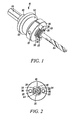
- an arbor embodying the present invention is indicated generally by the reference numeral 10.
- the arbor 10 is usable with hole cutters, such as hole saws and sheet metal hole cutters.
- hole cutter is used herein to mean any of numerous different types of cutting tools for cutting holes in work pieces, such as hole saws, sheet metal hole cutters, etc.
- arbor is used herein to mean any of numerous different types of devices for supporting a rotating tool, such as a hole cutter, on a power tool such as a drill, and further includes, without limitation, mandrels. As shown, for example, in FIGS.
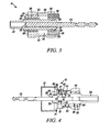
- a typical quick change hole cutter 12 includes an end plate 14 defining a hole cutter aperture 16 extending through a central portion of the end plate, and at least one drive pin aperture 18 radially spaced relative to the aperture 16.
- any number of drive pin apertures may be provided in any of a variety of shapes and/or configurations. As shown typically in FIG.
- a blade extends axially from the end plate 14 and defines a plurality of cutting teeth for cutting a hole in a work piece by rotatably driving the arbor 10 and hole cutter 12 and moving the rotatably-driven cutting teeth into the work piece.
- the aperture 16 defines a plurality of raised threaded portions 17 that are angularly spaced relative to each other for threadedly engaging a connecting end portion 22 of the arbor 10, and a plurality of recessed unthreaded portions 19 located between the threaded portions.
- the central aperture in the end plate or cap of the hole cutter defines a continuous or substantially continuous thread extending about the circumference of the aperture.
- Such standard hole cutters conform to the ASME B94.54-1999 standard, and in accordance with such ASME standard, define a standard thread form depending on the outside diameter of the hole saw as follows: For hole saws having outside diameters between 9/16 inch and 1-3/16 inches, the standard thread form is a 1/2-20 UNF-2B thread, and for hole saws having outside diameters between 1-114 inches and 6 inches, the standard thread form is a 5/8-18 UNF-2B thread.
- standard hole cutter is used herein to mean a hole cutter that has such a threaded aperture; whereas the term “quick change” hole cutter is used herein to mean a hole cutter that does not include a such a conventional threaded aperture, but rather includes a connecting aperture defining one or more features to facilitate a quick change attachment of the hole cutter to the arbor, such as the plural raised engagement portions and plural recessed portions located therebetween and described further below.
- the arbor 10 comprises an axially-elongated arbor body 20 defining an axially extending pilot bit aperture 29 for receiving a pilot bit, such as a quick change pilot bit 64 ( FIG. 18 ) or a standard pilot bit 66 ( FIG. 19 ).
- a standard pilot bit is a pilot bit that does not include a feature for allowing attachment of the bit to an arbor without tools.
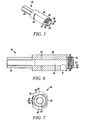
- the arbor body 20 includes a body portion 26 defining a stop surface 28, and an end portion 22 that extends axially from the stop surface 28 and defines an end surface 33. As described further below, the end portion 22 is engageable within the hole cutter aperture 16 ( FIG. 4 ) to secure the arbor body to the hole cutter.
- the end portion 22 threadedly engages the hole cutter aperture 16; however, as may be recognized by those of ordinary skill in the pertinent art based on the teachings herein, any of numerous other connection mechanisms or features that are currently known, or that later become known, equally may be employed. As can be seen in FIGS.
- the body portion 26 of the arbor defines a "double D" cross-sectional configuration (i.e., a pair of opposing substantially flat side surfaces with a pair of opposing substantially curvilinear side surfaces extending therebetween); however, as may be recognized by those of ordinary skill in the pertinent art based on the teachings herein, this configuration is only exemplary, and numerous other shapes and/or configurations that are currently known, or that later become known equally may be used.
- a drive shank 24 is formed on the arbor body 20 opposite the end portion 22. In the illustrated embodiment, the drive shank 24 is a quick-release power drive shank of a type known to those of ordinary skill in the pertinent art.
- shank 24 may take the form of any of numerous different types of shanks or other structures that are currently known, or that later become known for performing the function of the shank 24.
- the arbor 10 further includes a drive pin plate or member 30 defining an aperture 32 extending therethrough.
- the aperture 32 is configured for receiving the arbor body 20 and engaging the body portion 26 of the arbor body such that the drive pin plate 30 is prevented from rotating relative to the arbor body, but is allowed to move axially over the arbor body between a first position engaging the hole cutter 12 ( FIG. 14A ), and a second position disengaged from the hole cutter 12 ( FIG. 14B ).
- FIG. 14A first position engaging the hole cutter 12
- FIG. 14B a second position disengaged from the hole cutter 12
- the aperture 32 defines a "double D" configuration to matingly engage the body portion 26 of the arbor body 20; however, as may be recognized by those of ordinary skill in the pertinent art based on the teachings herein, this configuration is only exemplary, and numerous other shapes and/or configurations that are currently known, or that later become known equally may be used.
- the drive pin plate 30 further includes a first or hole cutter bearing surface 34, and a plurality of retaining members, which in the illustrated embodiment are drive pins 36.
- the drive pins 36 extend axially from the first surface 34, are angularly spaced relative to each other, and are radially spaced relative to the aperture 32.
- Each drive pin 36 is received within a corresponding drive pin aperture 18 of the hole cutter 12 when the drive pin plate 30 is in a first (engaged) position engaging the hole cutter ( FIGS. 4 and 14A ), and is displaced from the respective drive pin aperture 18 when the drive pin plate is in a second (disengaged) position disengaged from the hole cutter ( FIG. 14B ).
- the drive pin plate 30 includes two diametrically opposed drive pins 36; however, as may be recognized by those of ordinary skill in the pertinent art base on the teachings herein, the drive pin plate 30 can take any of numerous different configurations and can include any number of drive pins 36 that can take any of numerous different configurations that are engageable with corresponding drive pin apertures 18 or other recesses in the hole cutter.
- a biasing member 38 biases the drive pin plate 30 in the direction from the second disengaged position toward the first engaged position. As described in further detail below, the biasing member 38 normally biases the drive pin plate 30 into the first engaged position when the drive pins 36 and corresponding drive pin apertures 18 are placed in alignment, such that the drive pin plate 30 abuts the end plate 14 of the hole cutter 12, and supports the hole cutter in a manner that substantially prevents off-axis wobble and undesirable vibrations during use.
- One advantage of this feature is that it facilitates one-handed attachment of the hole cutter to the arbor, or otherwise facilitates rapid attachment and detachment of the hole cutter to and from the arbor.
- the arbor 10 is adapted to receive and mount both quick change hole cutters and standard hole cutters.
- the invention thereof may be embodied in arbors adapted to mount only quick change hole cutters.
- a standard hole cutter (not shown)
- the threaded aperture in the end plate of the hole cutter (defining, for example, either a 1/2-20 UNF-2B thread or a 5/8-18 UNF-2B thread, depending on the outer diameter of the hole saw) threadedly engages the end portion 22 of the arbor body 20 to secure the arbor body thereto.
- the quick change hole cutter 12 on the other hand, and as shown typically in FIG.
- the aperture 16 in the end plate 14 defines a plurality of curvilinear protrusions 17 angularly spaced relative to each other along the circumference of the aperture, and a plurality of curvilinear recesses 19 located therebetween.
- the curvilinear protrusions 17 define female threads that threadedly engage corresponding male threads formed on the end portion 22 of the arbor body 20. More specifically, and as shown in FIGS.
- the end portion 22 of the arbor body 20 defines a plurality of angularly extending, curvilinear arbor protrusions 23 that project radially outwardly, and are angularly spaced relative to each other about the circumference of the end portion 22, and a plurality of angularly extending recesses or flats 25 located therebetween.
- one or more of the protrusions 23 on the arbor body 20 and the corresponding protrusions 17 on the hole cutter 12 defines a greater or lesser angular extent than the other protrusions so that the quick change hole cutter can be fitted to the end portion 22 of the arbor body in only one first engagement position, and in that first engagement position, the lead male and female threads can properly engage when moving from the first engagement position to the second engagement position. More specifically, as shown typically in FIG. 7 , a first protrusion 23 on the end portion 22 of the arbor body to the right in the drawing defines a greater angular extent than the opposite second protrusion 23 located to the left in the drawing. Similarly, the hole saw cap 14 of FIG.
- first recess 19 defining a greater angular extent than the opposite second recess 19. Accordingly, in the first engagement position, the first recess 19 receives the first protrusion 23, the second recess 19 receives the second protrusion 23, and this is the only position in which the end portion 23 of the arbor can be received within the central aperture of the hole cutter. In this first engagement position, the lead threads of the respective protrusions of the arbor and hole saw engage upon moving at least one of the hole cutter and arbor body relative to the other between the first and the second engagement positions.
- the end portion 22 of the arbor body can be received into the aperture 16 of the hole saw cap in only one position, and in that position, the lead male and female threads can engage upon moving the hole cutter and/or arbor body relative to the other between the first and second engagement positions.
- the hole cutter and/or arbor can include visual markings thereon that can be aligned or otherwise used to orient the position of the hole cutter aperture relative to the connecting portion of the arbor in order to ensure attachment of the hole to the arbor in the first engagement position.
- the protrusions 23 on the end portion 22 of the arbor body 20 are aligned with the correspondingly-sized recesses 19 of the hole cutter aperture 16. Then, the hole cutter 12 is slipped over the end portion 22 of the arbor body 20 (or vice versa) until the end plate 14 of the hole cutter is adjacent to, substantially in contact with, or in contact with the shoulder 28 of the arbor body 20 to thereby place the hole cutter and arbor body in the first engagement position. As indicated above, in this position, the lead male threads of the arbor body and lead female threads of the hole cutter can engage upon rotating at least one relative to the other.
- the hole cutter 12 is rotated relative to the arbor body 20 from the first engagement position to a second engagement position (or the arbor body is rotated relative to the hole cutter, or both the hole cutter and arbor body are rotated in opposite directions) to, in turn, threadedly engage the male threaded protrusions 23 of the end portion 22 of the arbor body with the corresponding female threaded protrusions 17 of the hole cutter, and thereby fixedly secure the hole cutter to the arbor body.
- the male threads of the arbor body protrusions 23 and the female threads of the hole cutter protrusions 17 are configured (or “clocked") so that when the hole cutter and/or arbor body is rotated from the first engagement position to the second engagement position, the drive pins 36 of the arbor and drive pin apertures 18 of the hole cutter are substantially aligned in the second engagement position to, in turn, allow the drive pins to be axially received within the drive pin apertures and thereby further secure the hole cutter to the arbor.
- the male and female threads of the protrusions 23 and 17, respectively are preferably configured so that when the hole cutter 12 and/or the arbor body 20 are rotated into the second engagement position, the end plate 14 is in contact with, or substantially in contact with the shoulder 28 of the arbor body to, in turn, allow the shoulder to engage and further support the hole cutter during use.
- one advantage of the currently preferred embodiments of the present invention is that the threaded end portion 22 of the arbor is threadedly engageable with either quick change hole cutters or standard hole cutters.
- the combination of threaded protrusions 23 on the end portion 22 of the arbor body 20 forms an interrupted, but continuous thread pattern for engaging the female threads on a standard hole cutter as defined above (e.g., either a 1/2-20 UNF-2B thread or a 5/8-18 UNF-2B thread, depending on the outer diameter of the hole saw).
- the threaded aperture in the standard hole cutter cap is fitted over the threaded end portion 22 of the arbor body, and at least one of the hole cutter and arbor body is rotated relative to the other to engage the threads. Then, the hole cutter and/or arbor is rotated relative to the other to further engage the threads and, in turn, axially move the end cap of the hole cutter into engagement with the shoulder 28 of the arbor body ( FIG. 7 ). In this position, if the drive pins 36 are aligned with the drive pin apertures of the standard hole cutter, then the drive pin plate is moved downwardly, or allowed to move downwardly into engagement with the end plate on the hole cutter to, in turn, receive the drive pins within the drive pin apertures.
- the hole saw is rotated and backed away slightly from the shoulder 28 of the arbor until the drive pin apertures and drive pins are aligned.
- the drive pin plate is moved downwardly, or allowed to move downwardly into engagement with the drive pin apertures to complete the connection of the hole cutter to the arbor.
- the relative rotation of the hole cutter 12 and/or arbor 10 between the first and second engagement positions is within the range of about 10 degrees and about 180 degrees, is preferably within the range of about 30 degrees and about 120 degrees, and is most preferably within the range of about 40 degrees and about 100 degrees. In the illustrated embodiment, the relative rotation between the first and second engagement positions is about 45 degrees.
- these angular ranges and angles are only exemplary, and numerous other angles and/or angular ranges equally may be employed.
- the arbors and hole cutters of the currently preferred embodiments of the present invention define custom thread forms that allow the end portions of the arbors to be threadedly engaged to both quick change hole cutters and standard hole cutters; that allow the quick change hole cutters to engage or substantially engage the shoulder of the arbor in both the first and second engagement positions; and that are timed so that in the second engagement position the drive pins of the arbor are aligned or substantially aligned with the drive pin recesses of the hole cutter.
- standard hole cutters having hole saw diameters of 1-3/16 inches or less define a 1/2-20 UNF-2B thread ("small diameter” hole cutters), and standard hole cutters having hole saw diameters of 1-1/4 inches or greater define a 5/8-18 UNF-2B thread ("large diameter” hole cutters).
- the custom thread forms of the currently preferred embodiments of the present invention are based on these standard thread forms to allow attachment of the arbor to hole cutters with such standard threads; however, the custom thread forms also vary from the standard thread forms in order to allow attachment of quick change hole cutters as described.
- the currently preferred embodiments of the present invention define a "1/2-20 custom thread" for relatively small diameter hole cutters, and a "5/8-18 custom thread" for relatively large diameter hole cutters.
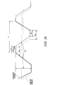
- Each custom thread defines the same thread height "H”, pitch "P”, and included angle “B”, as the respective standard thread form, but defines a different axial clearance "a", root” R, and crest “C”.
- the customer thread forms differ from the standard thread forms as follows: Table 1 Different Features Standard Thread Forms Custom Thread Forms Root (“R") 0.25 P 0.25 P + a Crest (“C”) 0.125 P 0.125 P - a Axial Clearance Not Specified, But Negligible or Approximately Zero a
- D the degree of rotation between the first and second engagement positions.
- the minimum axial clearance "a” is set to time the threads so that in the second engagement position the drive pins are aligned or substantially aligned with the respective drive pin recesses in the hole cutter to allow the drive pins to be moved into the engaged position.
- Table 2 Number of Lobes (or curvilinear threaded protrusions) Angular Rotation Between First And Second Engagement Positions Minimum Approximate Clearance "a” for 5/8-18 Custom Thread Form (inches) Minimum Approximate Clearance "a” for 1/2-20 Custom Thread Form (inches) 2 lobe (square/rectangle) 90° 0.014 0.012 3 lobe (triangle) 60° 0.009 0.008 4 lobe (cross) 45° 0.007 0.006 5 lobe (pent) 36° 0.006 0.005 6 lobe (hex) 30° 0.005 0.004
- the minimum clearance "a" is approximately as defined above; however, if desired, the clearance may be greater than the minimum as defined above. In some embodiments of the present invention, the clearance is within the range of about 1 to about 1-1/2a. If, for example, the clearance is greater than the respective minimum clearance "a", the drive pins will be allowed to move into the drive pins recesses when the hole cutter is located in the second engagement position. If, on the other hand, the clearance is too small such that the hole cutter cannot move into the second engagement position and thus cannot move the drive pin recesses into alignment with the drive pins, the hole cutter cannot be properly attached to the arbor.
- the arbor 10 further includes a pilot bit mechanism 40, at least a portion of which is housed in the arbor body 20 and/or a housing in the drive pin plate 30.
- the pilot bit mechanism 40 is designed to allow substantially automatic and/or manual engagement and disengagement of both quick change and standard pilot drill bits ( FIGS. 18-19 ).
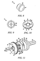
- the pilot bit mechanism 40 defines a quick change pilot bit state, shown in FIG. 4 , a standard pilot bit state, shown in FIG. 16 , and a neutral state shown in FIG. 17 . In the quick change pilot bit state shown in FIG.
- the pilot bit mechanism 40 engages a quick change pilot bit 64 to prevent movement of, and otherwise releasably secure the bit to the arbor body 20; in the standard pilot bit state shown in FIG. 16 , the pilot bit mechanism 40 engages a standard pilot bit 66 to prevent movement of, and otherwise releasably secure the bit to the arbor body 20; and in the neutral state shown in FIG. 17 , the pilot bit mechanism 40 is disengaged from the respective quick change pilot bit 64 or standard pilot bit 66 (whichever one is inserted in the pilot bit aperture 29) to release, remove and/or replace the bit.
- the pilot bit mechanism 40 may include a visual indicator that alerts a user when a standard pilot bit 66 is inserted in the pilot bit aperture 29.
- the pilot bit mechanism 40 comprises a pilot pin 41 (shown separately in FIGS. 8-9 ) movable between a first position and a second position.
- the first position corresponds with the quick change pilot bit state wherein the pilot pin engages the quick change bit 64 ( FIG. 4 ).
- the second position corresponds with either the standard pilot bit or neutral states wherein the pilot pin is either disengaged from the quick change bit, as shown in FIG. 17 , or positioned to allow a standard bit 66 to be inserted into the arbor body 20, as shown in FIG. 16 .
- FIG. 8-9 the pilot bit mechanism 40
- the first position corresponds with the quick change pilot bit state wherein the pilot pin engages the quick change bit 64 ( FIG. 4 ).
- the second position corresponds with either the standard pilot bit or neutral states wherein the pilot pin is either disengaged from the quick change bit, as shown in FIG. 17 , or positioned to allow a standard bit 66 to be inserted into the arbor body 20, as shown in FIG. 16 .
- the quick change pilot bit 64 includes a shank defining at least one pilot pin engaging feature 65 such as, for example, a groove, recess, aperture, notch, indentation, external boss or protrusion.
- the quick change bit 64 has a rectangular notch for engaging the pilot pin 41; however, as may be recognized by those of ordinary skill in the pertinent art based on the teachings herein, the quick change shank may take the form of any of numerous different types of shapes, and may include any of numerous different configurations or features that are currently known or that later become known for engaging the pilot pin.
- the pilot pin 41 has a substantially rounded tip 42.
- the pilot bit mechanism 40 includes a biasing member 43, such as a coil spring, that biases the pilot pin 41 into the first position in engagement with a pilot bit received within the pilot bit aperture 29.
- the pilot bit mechanism 40 further comprises a fastener 48 movable between a first position ( FIG. 4 ) disengaged from a pilot bit received within the pilot bit aperture 29, and a second position engaged with either a quick change 64 or standard pilot bit 66 received within the pilot bit aperture 29.
- the fastener 48 is a set screw; however, as may be recognized by those of ordinary skill in the pertinent art based on the teachings herein, the fastener may take the form of any of numerous other types of fasteners that are currently known, or that later become known for releasable securing the inserted pilot bit.
- the pilot bit mechanism 40 further comprises a shear pin or ball 46 that is disposed at least partially within a ball receiving aperture 39 defined in the drive pin plate 30.
- the ball 46 is movable between a first position, wherein the ball 46 outwardly protrudes from the ball receiving aperture 39 when the pilot bit mechanism 40 is in the quick change pilot bit or standard pilot bit states, as shown in FIGS. 4 and 16 , and a second position, wherein the ball 46 is substantially retained within the ball receiving aperture 39 when the pilot bit mechanism 40 is in the neutral state, as shown in FIG. 17 .
- a biasing member 47 biases the ball 46 into the first position.
- biasing members 38, 43 and 47 are coil springs; however, as may be recognized by those of ordinary skill in the pertinent art based on the teachings herein, the biasing members may take the form of any of numerous different types of biasing members that are currently known, or that later become known, such as any of numerous different types of springs or other components.
- the pilot bit mechanism 40 further comprises a shear plate 44 defining an aperture 45 for receiving therein the pilot pin 41 and/or ball 46 depending on the state of the pilot bit mechanism.
- the shear plate 44 is movable between a first position corresponding to the quick change pilot bit state shown in FIG. 4 , and a second position corresponding to the standard pilot bit and neutral states of the pilot bit mechanism 40 shown in FIGS. 16-17 .
- the interaction between the shear pin 41, shear plate 44, ball 46, drive pin plate 30 and pilot bit define the three states of the pilot bit mechanism.
- Other components of the arbor 10 may also play a role in defining the states the pilot bit mechanism; however, attention will be focused on the above-mentioned components.
- FIG. 17 the neutral state of the pilot bit mechanism 40 is shown. From the neutral state, the pilot bit mechanism 40 can move into either the quick change pilot bit state ( FIG. 4 ) or the standard pilot bit state ( FIG. 16 ) depending on the type of pilot bit being used (i.e. quick change bit 64 or standard bit 66).
- the pilot bit mechanism 40 is disengaged from the pilot bit while in the neutral state, which allows for the removal or insertion of any type of pilot bit.
- the drive pin plate 30 In the neutral state, the drive pin plate 30 is in its respective second or disengaged position ( FIGS. 14B and 17 ). In this position, the pilot pin aperture 31, the shear plate aperture 45 and the ball receiving aperture 39 are substantially aligned, allowing the pilot pin 41 and ball 46 to move freely between their respective first and second positions depending on the type of pilot bit inserted into the pilot bit aperture 29.
- a quick change pilot bit 64 is inserted into the pilot bit aperture 29, and with the drive pin plate 30 in its second or disengaged position ( FIG. 17 ), the pilot bit mechanism 40 is positioned to transform from the neutral state to the quick change pilot bit state to engage the quick change pilot bit 64.
- the pilot pin 41 is biased inwardly by its associated biasing member 43 into the recess 65 of the quick change pilot bit 64 to secure the bit 64; accordingly, the ball 46 is biased inwardly by its associated biasing member 47 into the shear plate aperture 45, so that the ball 46 engages the shear plate 44.
- the position of the shear plate 44 is fixed relative to the drive pin plate 30 so that any movement of the drive pin plate 30 between its first and second positions causes the shear plate 44 to move between its first and second positions.
- the drive pin plate 30 To enter the quick change pilot bit state from the neutral state, the drive pin plate 30 must be moved from its second position ( FIGS. 14B and 17 ) to its first position ( FIGS. 4 and 14A ), which, in turn, causes the shear plate 44 to move from its second position ( FIG. 17 ) to its first position ( FIG. 4 ).
- the shear plate 44 prevents outward movement of the pilot pin 41 to thereby releasably lock the pilot pin 41 in engagement with the quick change pilot bit 64 and secure the bit in the pilot bit aperture 29.
- the pilot bit mechanism 40 is positioned to transform from the neutral state to the standard pilot bit state to engage the standard pilot bit 66.
- the standard pilot bit state shown in FIG. 16
- the standard pilot bit 66 having been inserted into pilot bit aperture 29 maintains the pilot pin 41 in its second position so that a portion of the pilot pin 41 is seated within the shear plate aperture 45.
- the pilot pin 41 engages the shear plate 44 so that the axial position of the shear plate 44 is fixed relative to the arbor body 20.
- the drive pin plate 30 To enter the standard pilot bit state from the neutral state, the drive pin plate 30 must be moved from its second position ( FIGS.
- the shear plate 44 will not move from its second position to its first position when the drive pin plate 30 is moved; instead, the shear plate 44 will remain in its second position as a result of being engaged by the pilot pin 41.
- the ball 46 is biased into contact with the outer surface of the shear plate 44 further preventing the shear plate 44 from moving out of its second position.
- the fastener 48 is moved into engagement with the pilot bit 66 to secure the bit within the bit aperture 29, which in turn, maintains the pilot pin 41, shear plate 44 and ball 46 in their respective positions associated with the standard pilot bit state ( FIG.
- an end of the shear plate 44 protrudes visibly outwardly to provide a visual indication that a standard pilot bit is being used, and thus functions as visual alert to the user to manually engage the fastener 48 and, in turn, fixedly secure the standard pilot bit.
- the arbor 10 further comprises a collar 50.
- the collar 50 defines a peripheral, axially-extending side wall 52, a bore 53 formed on the inner side of the side wall 52, and an expanded recess 55 formed on the inner end of the bore for receiving therein the drive pin plate 30 that is fixedly secured or coupled thereto.
- the collar 50 is movable between first and second positions corresponding to the engaged and disengaged positions of the drive pin plate 30, respectively, so that movement of the collar from the first to the second position substantially simultaneously moves the drive pin plate 30 from the engaged to the disengaged position.
- the inner bore 53 of the collar 50 and the body portion 26 of the arbor body 20 define an annular, axially-extending compartment 56 for receiving and supporting therein the first biasing member 38 which, in the illustrated embodiment, is a coil spring, which biases the drive pin plate (and collar) towards the engaged position.
- the first biasing member 38 which, in the illustrated embodiment, is a coil spring, which biases the drive pin plate (and collar) towards the engaged position.
- the collar is an elongated member defining a spool-like or diabolo shape. More specifically, the collar 50 defines an upper (distal) portion 57 defining a first laterally-extending diameter D1 and an outer surface 67, a middle portion 58 defining a second laterally-extending diameter D2 and an outer surface 68, and a lower (proximal) portion 59 defining a third laterally-extending diameter D3 and an outer surface 69.
- the collar 50 can take on of any of numerous different shapes and configurations that are currently known or that later become known, and thus, is not limited to the spool-like or diabolo shape shown.
- the first laterally-extending diameter D1 is approximately the same as the third laterally-extending diameter D3, and the second laterally-extending diameter D2 is smaller than the first and second laterally extending diameters, thus forming the spool-like or diabolo shape.
- an advantage of this shape is that it provides an improved manually engageable surface that facilitates handling during use by permitting the user to grasp the middle portion 58 of the collar 50 with, for example, an index finger and thumb of one hand, when moving the collar 50 to attach or remove a hole cutter 12.
- the laterally-extending diameters of the upper and lower portions are approximately the same in the illustrated embodiment, in some embodiments the laterally extending diameters may differ; although such diameters preferably remain greater than the laterally-extending diameter of the middle portion.
- the axial length of the collar 50 is between about 1/2 inch to about 1-3/8 inches, and in an exemplary embodiment, the axial length of the collar 50 is about 1-1/5 inches. Additionally, in one embodiment of the invention, the axial length of the upper portion of the collar is between about 1/6 inch to about 1/2 inch, the axial length of the middle portion of the collar is between about 1/4 inch to about 3/4 inch, and the axial length of the lower portion of the collar is between about 1/6 inch to about 1/2 inch. In an exemplary embodiment, the axial length of the upper portion is about 1/3 inch, the axial length of the middle portion is about 2/5 inch, and the axial length of the lower portion is about 1/5 inch.
- the outer surfaces 67, 68, 69 of the respective upper, middle and lower portions 57, 58, 59 are substantially planar and substantially parallel to the central longitudinal axis of the arbor body 20.
- the upper and lower portions of the collar 50 do not directly abut the middle portion; rather, intermediate portions 71, 73 reside between the upper portion 57 and the middle portion 58 and the lower portion 59 and the middle portion 58 respectively.
- the intermediate portions 71, 73 define surfaces 75, 77 that slope towards the central longitudinal axis of the arbor body -- i.e., the surfaces 75, 77 slope in a direction from the upper and lower portions of the collar 57,59 toward the middle portion 58 of the collar.
- the upper, middle and lower portions 57, 58, 59 of the collar 50 can take on any of numerous different configurations that are currently known or that later become known; for example, the middle portion could include a plurality of axially spaced ribs, or any of the upper, middle and lower portions could take on an arcuate, curvilinear or sloped configuration. Additionally, the upper and lower portions could directly abut the middle portion without the inclusion of the intermediate portions, or the intermediate portions could take on any of numerous different configurations that are currently known or that later become known; for example, the intermediate portions could take on an arcuate or curvilinear configuration.
- the collar 50 and drive pin plate 30 can be integrated into a single component that can take on a diabolo configuration as defined above, or can take on any of numerous different configurations that are currently known or that later become known; for example, the single collar/drive pin plate component could take on a cylindrical shape having the same laterally extending diameter throughout.
- the arbor 10 includes a retaining clip or ring 60 connectable to a groove 62 formed in the body portion 26 of the arbor body 20, a bushing 61 that engages on its end surface the clip 60, and slidably engages on its outer surface the bore 53 of the collar 50 to guide the axial movement of the collar and drive pin plate between the first engaged ( FIGS. 4 and 14A ) and second disengaged ( FIG. 14B ) positions.
- the first biasing member 38 is axially fitted between the bushing 60 and the inner end of the drive pin plate 30 to normally bias the drive pin plate (and collar) outwardly into the first engaged position.
- a user can manually engage the collar 50 to retract the collar against the bias of the first biasing member 38 into the disengaged position and can, in turn, release the collar to allow the first biasing member to drive the collar and drive pin plate from the disengaged to an engaged position.
- a user can press the hole cutter cap 14 against the drive pin plate 30 to, in turn, correspondingly compress the coil spring 38 and place the hole cutter against the shoulder 28 of the arbor in the first engagement position. Then, upon rotating the hole cutter with the same hand from the first engagement position into the second engagement position, the coil spring automatically drives the drive pin plate 30 into the engaged position with the drive pins 36 received within the drive pin apertures of the hole cutter to complete attachment of the hole cutter to the arbor.
- the hole cutter is fitted onto the end portion 22 of the arbor body 20 such that the arbor body protrusions 23 are received within the corresponding hole cutter recesses 19, and the base of the hole cutter 14 rests on or about the stop surface 28.
- the user substantially simultaneously moves the drive pin plate 30 from the first position to the second position and compresses the first biasing member 38 as shown, for example, in FIG. 14B .
- the hole cutter is then rotated from the first engagement position to the second engagement position such that the hole cutter protrusions 17 threadedly engage the respective arbor body protrusions 23 and, in turn, releasably secure the hole cutter to the arbor body.
- the drive pin apertures 18 of the hole cutter are substantially aligned with the respective drive pins 36 of the drive pin plate 30, thereby allowing the first biasing member 38 to automatically drive the drive pin plate from the second position ( FIG. 14B ) to the first position ( FIG. 14A ) and, in turn, drive the drive pins 36 into the corresponding drive pin apertures 18 as shown, for example, in FIG. 15 .
- the hole cutter 12 is fully engaged and attached to the arbor as shown, for example, in FIG. 4 .
- the end user aligns the hole cutter aperture with the end portion 22 of the arbor body 20 fitting the hole cutter thereupon, such that the hole cutter aperture threadedly engages the threads on the arbor protrusions 23.
- the standard hole cutter is then rotated to threadedly attach the hole cutter to the end portion of the arbor and receive the drive pins into the corresponding drive pin apertures of the hole cutter.
- the standard hole cutter may not engage or may not fully engage the shoulder or stop surface of the arbor when attached to the arbor; however, since the drive pins drive the hole cutter it is not always necessary that the hole cutter cap engage the stop surface of the arbor.
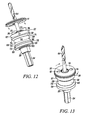
- the drive pin plate 30 is moved from the first position engaging the hole cutter 12 to the second position disengaged from the hole cutter 12 by at least one of: (i) grasping and physically moving the drive pin plate 30, and (ii) pressing downward on the drive pin plate 30 through engagement with the hole cutter 12 during the step of fitting the hole cutter onto the end portion of the arbor body ( FIG. 12 ).
- the quick change pilot bit 64 is then inserted into the pilot bit aperture 29.
- the pilot pin 41 moves from the first position to the second position, wherein the pilot pin 41 slides into the pilot pin aperture 31 formed in the arbor body 20 and at least a portion of the pilot pin 41 enters the shear plate aperture 45 (see, for example, FIG. 17 ).
- the ball or pin 46 moves from the first position to the second position. In the second position, the ball 46 at least partially exits the shear plate aperture 45 and at least partially enters the ball receiving aperture 39 formed in the drive pin plate 30.
- the biasing member 43 returns the pilot pin 41 to the first position such that the pilot pin 41 engages the respective quick change feature 65 of the bit 64 and prevents movement of the quick change pilot bit 64 relative to the arbor body.
- the biasing member 47 returns the ball 46 to the first position. In the first position, a portion of the ball 46 is received by the shear plate aperture 45 and engages the shear plate 44, while a portion of the ball remains in the shear pin aperture 31 of the arbor body 20.
- the drive pin plate 30 is then moved from the second position to the first position engaging the hole cutter by at least one of: (i) releasing the drive pin plate 30, and (ii) during the step of rotating the hole cutter, allowing the drive pin plate 30 to move when the drive pin apertures 18 align with the corresponding drive pins 36.
- the shear plate 44 substantially simultaneously moves from the second position to the first position. In the first position, the shear plate 44 locks the pilot pin 41 into engagement with the quick change pilot bit 64, and thereby prevents the pilot bit from moving out of the first position as shown, for example, in FIG. 4 .
- the drive pin plate 30 is moved from the first position engaging the hole cutter to the second position disengaged from the hole cutter by at least one of: (i) grasping and physically moving the drive pin plate 30, and (ii) pressing downward on the drive pin plate 30 through engagement with the hole cutter 12 during the step of fitting the hole cutter onto the end portion of the arbor body ( FIG. 12 ).
- the standard pilot bit 66 is then inserted into the pilot bit aperture 29. As the pilot bit 66 is inserted, the pilot pin 41 moves from the first position to the second position.
- the pilot pin 41 slides into the pilot pin aperture 31 in the arbor body 20 and at least a portion of the pilot pin 41 enters the shear plate aperture 45 and engages the shear plate 44 (see FIG. 16 ), thereby allowing the pilot pin 41 to exit the pilot pin aperture 29 and enabling full insertion of the standard pilot bit 66.
- the ball 46 moves from the first position to the second position. In the second position, the ball 46 exits the shear plate aperture 45 and enters the ball receiving aperture 39 in the drive pin plate 30.
- the drive pin plate 30 is then moved from the second position to the first position engaging the hole cutter by at least one of: (i) releasing the drive pin plate 30, and (ii) during the step of rotating the hole cutter, causing the drive pin plate 30 to move when the drive pin apertures 18 align with the corresponding drive pins 36.
- the shear plate 44 remains in the second position due to engagement with the pilot pin 41, which in turn, causes the ball 46 to partially extend outwardly from the ball receiving aperture 47 and into engagement with the shear plate 44 to further maintain the shear plate 44 in the second position.
- the shear plate 44 visually protrudes from behind the drive pin plate 30 to alert the user to use the fastener 48 to engage the standard pilot pit 66, which occurs when the drive pin plate 30 is in the first position and the shear plate 44 in the second position.
- the user moves the fastener 48 from the first position to the second position, thereby engaging the pilot bit 66 and preventing movement thereof relative to the arbor body.
- a user may employ the fastener 48 to secure a quick change pilot bit 64 in addition to the securement provided by the pilot bit mechanism 40.
- the order in which the respective hole cutter and pilot bit are mounted is inconsequential; rather, the hole cutter may be mounted before the pilot bit, after the pilot bit, or at about the same time as the pilot bit.
- the arbor can be used with the hole cutter only (no pilot bit) or with the pilot bit only (no hole cutter).
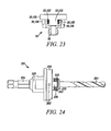
- FIGS. 20 and 21 another arbor embodying the invention is indicated generally by the reference number 110.
- the arbor 110 is substantially similar to the arbor 10 described above in connection with FIGS. 1-19 , and therefore like reference numerals preceded by the numeral "1" are used to indicate like elements.
- the primary difference of the arbor 110 in comparison to the arbor 10 described above, is that the arbor 110 does not include a collar 50 and biasing member 38 (see, e.g., FIGS 1 and 3 above), but rather includes a nut 150 that threadedly engages the body portion 126 of the arbor body 120, and an o-ring 151 extending annularly about the body portion between the nut 150 and drive pin plate 130.
- the nut 150 is movable axially over the body portion 126 by rotating the nut to, in turn, move the nut between a first position spaced away from a hole cutter (not shown) attached to the connecting portion 122, as shown typically in FIGS. 20 and 21 , and a second position engaging the drive pin plate 130 with the drive pins 136 received within the drive pin apertures of a hole saw to fixedly secure the drive pin plate to the hole saw (not shown).
- the o-ring 151 operates as a buffer between the nut 150 and drive pin plate 130 and otherwise allows a user to manually grip and turn the nut into engagement with the drive pin plate, and to manually grip and release the nut from the drive pin plate.
- the nut 150 and the collar 50 prevent the drive pin plates 30, 130 from slipping off the rearward end of the arbor body 20, 120, and the threaded protrusions 23, 123 prevent the drive pin plates from slipping off the front end of the arbor body when not in use.
- the arbors may include any of numerous different components that are currently known or that later become known for axially engaging the opposite side of the drive pin plate relative to the hole cutter to secure the axial position of the drive pin plate during use and/or to prevent the drive pin plate from slipping off the arbor body.
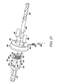
- an adapter for connecting relatively small hole cutters to the arbors of the invention is indicated generally by the reference numeral 70.
- the adapter 70 defines an adapter aperture 72 extending through an approximately central region thereof, a plurality of angularly extending protrusions 74 that project radially into the aperture 72 and are angularly spaced relative to each other about the periphery of the aperture, and a plurality of angularly extending recesses 76 formed between the protrusions 74.
- the protrusions 74 are threaded with a thread configuration that corresponds to and is engageable with the threaded portions 23, 123 of the end portions 22, 122 of the arbors 10, 110 for threadedly engaging the adapter to the arbors.
- the external periphery of the adapter 70 defines a plurality of curvilinear recesses 78 therein that are angularly spaced relative to each other about the external periphery, and are positioned relative to each other such that each recess 78 corresponds in position to, and receives therein a respective drive pin 36, 136 of the arbors when the adapter is attached to the arbor.
- the curvilinear shape of each recess 78 substantially conforms to the external shape of the respective drive pin to securely engage the respective drive pin and minimize any play therebetween.
- the underside of the adapter 70 includes a threaded boss 80 that is received within the threaded aperture on a hole cutter (not shown) to fixedly secure the hole cutter to the adapter. Accordingly, the adapter allows relatively small hole cutters that do not have drive pin apertures, or that do not have drive pin apertures that match the pattern of, or that otherwise are configured to receive the drive pins of the arbors.
- the adapter 70 is attached to the hole saw by threadedly attaching the boss 80 to the hole saw.
- the assembled adapter and hole saw are attached to the arbor by inserting the threaded protrusions 23, 123 of the arbor end portion 22, 122 into the recesses 76 of the adapter to define the first engagement position.
- at least one of the adapter/hole cutter assembly and arbor is rotated relative to the other to rotatably move from the first engagement position to the second engagement position.
- the protrusions 74 of the adapter threadedly engage the protrusions 23, 123 of the arbor to secure the adapter/hole cutter assembly to the arbor.
- the drive pins are moved axially into the curvilinear recesses 78 to further prevent any relative rotational movement of the adapter and arbor during use and to rotatably drive the hole cutter.
- the axial depth of the adapter may be set so that the inner surface of the adapter engages the drive pin plate in the second engagement position.
- the threads on the threaded protrusions may define an axial clearance as described above in order to facilitate maintaining contact between the adapter and arbor shoulder 28, 128 in the first and second engagement positions.
- FIGS. 24-27 another arbor embodying the present invention is indicated generally by the reference number 210.
- the arbor 210 is substantially similar to the arbors 10, 110 described above, and therefore like reference numerals preceded by the numeral "2", or preceded by the numeral "2" instead of the numeral "1", are used to indicate like elements.
- the primary difference of the arbor 210 in comparison to the arbor 10 described above, is that the arbor 210 does not include a biasing member 38 (see, e.g., FIGS 1 and 3 above) for biasing the drive pin plate 230 in the direction from the second disengaged position, where the drive pin plate 230 is disengaged from the hole cutter, to the first engaged position, where the drive pin plate engages the hole cutter.
- the drive pin plate 230 is manually moved between the engaged and disengaged positions without the aid of a biasing member, and is maintained in the first engaged position by a retaining member 280.
- the retaining member is a ball detent mechanism, which includes a ball 284 which is movable between a retracted position and an extended position, and a biasing member 286, such as a coil spring.
- the biasing member 286 biases the detent member 284 in the extended position.
- the ball detent 280 is housed within an aperture 282 defined in the drive pin plate 230.
- the aperture 282 extends radially between the drive pin plate aperture 232 and the outer surface of the drive pin plate 230.
- a set-screw 288 is threaded into the aperture 282 to provide a backing surface against which the spring 286 can compress and serve as a mechanism for adjusting the tension in the spring 286.
- the components of the ball detent mechanism may be substituted by any of numerous different components that are currently known or that later become known so long as the detent mechanism is able to secure the axial position of the drive pin plate relative to the arbor body during use and/or to prevent the drive pin plate from slipping out of engagement with the hole cutter.
- the retaining member 280 can be of any of numerous types of retaining members that are currently known or that later become known to secure the axial position of the drive pin plate relative to the arbor body during use and/or to prevent the drive pin plate from slipping out of engagement with the hole cutter.
- the arbor body 220 defines a groove 290 located about the perimeter of the arbor body 220 towards the end portion 222.
- the groove 290 defines a first surface that is curved and/or angled towards the drive shank 224 and a second surface 294 that is substantially straight or substantially parallel to the end surface 233 of the connecting end portion 222.
- the groove 290 is configured in this manner to allow rearward movement of the drive pin plate 230 from the first engaged position to the second disengaged position, and to prevent further forward movement of the drive pin plate 230 beyond the first engaged position.
- the ball 284 is movable between a retracted position and an extended position. In the extended position shown in FIG.
- a portion of the ball 284 is seated within the groove 290 and portion of the ball is seated within the aperture 282, thereby securing the drive pin plate 230 axially in its first engaged position relative to the arbor body 220 to maintain engagement with the hole cutter.
- the ball 284 In the retracted position, the ball 284 is recessed within the aperture 282, allowing the drive pin plate 230 to move axially over the arbor body 220 and disengage from the hole cutter.
- the drive pin plate 230 can define a spool-like or diabolo configuration as described above, with the same or approximately the same dimensions. Further, the drive pin plate can be elongated axially (with or without defining a spool-like diabolo shape) to define an axially elongated bearing surface between the drive pin plate 230 and the arbor body 220 to reduce or prevent unwanted movement or play between the drive pin plate and arbor body.
- a user grasps and manually moves the drive pin plate 30 rearward towards the drive shank 24.
- the ball 284 is forced against the curved and/or angled surface 292 of the groove 290 and, as the drive pin plate continues its rearward movement, the ball is forced out of the groove and into its retracted position within the aperture.
- the pilot pin plate 230 is moved to its second position disengaging the hole cutter and allowing removal of the hole cutter.
- the cutter is threaded onto the end portion 222 of the arbor body 220 as described above.
- the user grasps and manually moves the drive pin plate 230 in the forward direction away from the drive shank 224 until the aperture 282 is substantially aligned with the groove 290.
- the spring 286 biases the ball 284 into its extended position, thereby securing the axial position of the drive pin plate 230 relative to the arbor body 220 and into engagement with the hole cutter.
- FIGS. 29-32 another arbor embodying the present invention is indicated generally by the reference number 310.
- the arbor 310 is substantially similar to the arbor 210 described above, and therefore like reference numerals preceded by the numeral "3" instead of the numerals "2" are used to indicate like elements.
- a primary difference of the arbor 310 in comparison to the arbor 210 is that in the arbor 310 the drive pin plate is replaced by an axially-elongated collar 350.
- the arbor 310 comprises an axially-elongated arbor body 320 including a drive shank 324 on one end thereof, a threaded portion 322 on an opposite end thereof relative to the drive shank 324 that is engageable with the threaded aperture on the hole cutter (not shown), and an inner axially-extending bearing surface 327 located between the drive shank 324 and the threaded portion 322.
- the arbor body 320 further defines a first width W, which in the illustrated embodiment is a diameter, along the inner axially-extending bearing surface 327.
- the arbor 320 further comprises the aforementioned axially-elongated collar 350, which includes an upper or distal end 397, a lower or proximal end 399, and a middle portion 358 defining a manually engageable surface 368 extending axially between the proximal and distal ends.
- the middle portion 358 defines a reduced width or diameter D2 in comparison to the respective width or diameters D1, D3 of the proximal and distal ends.
- the collar 350 further includes a drive member, which in the illustrated embodiment is a pair of angularly spaced drive pins 336, extending axially from the distal end 397 of the collar 350.
- the collar 350 is slidably mounted on the arbor body 320 and movable between: (i) an engaged position with the distal end 397 of the collar 350 adjacent to the threaded portion 322 for engaging the drive member 336 with the drive member aperture of a hole cutter threadedly attached to the threaded portion 322 of the arbor body 320, and (ii) a disengaged position with the distal end 397 of the collar 350 axially spaced relative to the threaded portion 322 of the arbor body 320.
- the collar 350 further defines an outer axially-extending bearing surface 363 that slidably contacts the inner axially-extending bearing surface 327 of the arbor body 320 when moving the collar between the engaged and disengaged positions.
- the inner axially-extending bearing surface 327 defines a length L that is at least about 1-1/4 times the first width W of the arbor body; and preferably the axially-extending bearing surface defines a length L that is at least about 1-1/2 times the first width W of the arbor body.
- the arbor body 320 defines a pair of inner axially-extending bearing surfaces 327, 327' angularly spaced relative to each other, and a pair of inner curvilinear axially-extending bearing surfaces 385, 385' angularly spaced relative to each other between the inner axially-extending bearing surfaces 327, 327'.
- the collar 350 defines a pair of outer axially-extending bearing surfaces 363, 363' angularly spaced relative to each other, and a pair of outer curvilinear axially-extending bearing surfaces 389, 389' angularly spaced relative to each other between the outer axially-extending bearing surfaces 363, 363'.
- the pair of inner axially-extending bearing surfaces 327, 327' slidably engage the pair of outer axially-extending bearing surfaces 363, 363', and the pair of inner curvilinear axially-extending bearing surfaces 385, 385' slidably engage the pair of outer curvilinear axially-extending bearing surfaces 389, 389', when moving the collar 350 between the engaged and disengaged positions.
- the pair of inner axially-extending bearing surfaces 327, 327' are substantially flat and are located on substantially opposite sides of the arbor body 320 relative to each other
- the pair of outer axially-extending bearing surfaces 363, 363' are substantially flat and are located on substantially opposite sides of the collar 350 relative to each other.
- surfaces 327, 327', 363, 363' can take on any of numerous different configurations that are currently known or that later become known; for example, the surfaces could include a plurality of mating protrusions and recesses, and the surfaces need not be located on substantially opposite sides of the arbor body and collar respectively.
- each curvilinear axially-extending bearing surface 385, 385', 389, 389' is defined by a diameter of the collar 350 or arbor body 320, respectively.
- the outer axially-extending bearing surfaces 363, 363' are shorter than the inner axially-extending bearing surfaces 327, 327'.
- the collar 350 defines a pair of axially-extending recessed surfaces 391, 391' located on substantially opposite sides of the collar relative to each other, and each recessed surface 391, 391' extends between a respective axially-extending bearing surface 363, 363' and the proximal end 399 of the collar.
- the collar 350 further defines a pair of first stop surfaces 393, 393'.
- Each first stop surface 393, 393' is formed between an axially-extending recessed surface 391, 391' and a respective outer axially-extending bearing surface 363, 363'. Additionally, the arbor body 320 defines a pair of second stop surfaces 395, 395'. Each second stop surface 395, 395' is formed at a proximal end of a respective inner axially-extending bearing surface 327, 327'. The first and second stop surfaces are configured to engage each other when the collar 350 is in the disengaged position to prevent further proximal axial movement of the collar 350.
- the second stop surfaces 395, 395' are defined by respective lips 396, 396' formed on the arbor body 320, and the lips 396, 396' and recessed surfaces 391, 391' form bearing surfaces that slidably contact each other when moving the collar 350 between the engaged and disengaged positions.
- the collar 350 further defines a distal rim 357 at the distal end 397 of the collar, a proximal rim 359 at the proximal end 399 of the collar, and an annular manually engageable surface 368 extending between the proximal and distal rims.
- the distal and proximal rims 357, 359 are defined by a first diameter (D1 or D3)
- the manually engageable surface 368 is defined by a second diameter D2 that is less than the first diameter (D1 or D3).
- the second diameter D2 is within the range of about 70% to about 95% of the first diameter (D1 or D3); and most preferably, the second diameter D2 is within the range of about 80% to about 90% of the first diameter (D1 or D3).
- the proximal and distal rims are substantially defined by the first diameter (i.e. D1 equals D3).
- the manually engageable surface 368 defines an axial length L2, and the proximal and distal rims each define an axial length (L1 and L3, respectively), and the axial length of the manually engageable surface L2 is greater than the axial length of each of the proximal and distal rims L1, L3.
- the axial length L2 of the manually engageable surface is about 30% to about 60% greater than the axial length of each of the proximal and distal rims L1, L3.
- the arbor 310 further comprises a retaining member 380 mounted on the collar 350 and movable between (i) a first position holding the collar 350 in the engaged position, and (ii) a second position allowing axial movement of the collar 350 from the engaged position to the disengaged position.
- the retaining member 380 is a ball detent mechanism similar to the mechanism 280 described above.
- the retaining member 380 can be of any of numerous different types of retaining members that are currently known or that later become known to retain the axial position of the collar 350 relative to the arbor body 320 and/or to prevent the collar 350 from slipping out of engagement with the hole cutter (not shown) during use.
- the components of the arbor may take on any of numerous different configurations, or may be formed of any of numerous different materials, that are currently known, or that later become known; any of a variety of the disclosed components may be eliminated, or additional components or features may be added; and the arbors may be used with any of numerous different types of tools that are currently known, or that later become known.
- the retaining members may can be of any of numerous different types that are currently known or that later become known, such as, for example, cylindrical or tapered drive pins, that engage corresponding apertures on a hole cutter, or drive dogs defining flats that engage corresponding apertures or recesses on the hole cutter.
- the drive pin apertures or recesses can take any of numerous different configurations for receiving or otherwise engaging any of numerous different types of drive members.
- the drive pin member or plate can likewise can take any of numerous different configurations, including, for example, a plate form or a circular or other shaped collar or housing that is movable relative to the arbor body and includes one or more drive pins.
- the threads on the arbor connecting portion and/or on the central aperture of the hole cutter can take the form of the standard or timed threads (or combinations thereof) as described above, or can take the form of any of numerous different thread configurations that are currently known, or that later become known.
- the connecting portion and/or central aperture of the hole cutter may define a structure other than threads for engaging the hole cutter to the arbor upon moving the arbor and/or hole cutter relative to the other between the first and second engagement positions.
- the retaining member can be of any of numerous types of retaining members that are currently known or that later become known to secure or otherwise return the axial position of the drive pin plate and/or collar relative to the arbor body during use and/or to prevent the drive pin plate and/or collar from slipping out of engagement with the hole cutter; additionally, more than one retaining member could be employed. Accordingly, this detailed description of the currently-preferred embodiments is to be taken in an illustrative, as opposed to a limiting sense.
Description
- The present invention relates to a quick change hole cutter according to the preamble of
claim 1 and to an arbor according to the preamble ofclaim 2. - A typical arbor for a hole saw includes an arbor body with a threaded end portion that engages a corresponding threaded aperture in the end plate of the hole saw to secure the hole saw to the arbor. A pilot drill bit is receivable within the threaded end portion of the arbor body and extends through the center of the hole saw. The arbor further includes a drive pin plate that slidably mounts to the arbor body and has a pair of diametrically opposed drive pins that extend into corresponding drive pin holes formed in the end plate of the hole saw to rotatably drive the hole saw. A lock nut is threadedly mounted on the arbor body to prevent disengagement of the drive pins from the hole saw during use.
- To mount the hole saw to the arbor, the end plate of the hole saw is threaded onto the threaded end portion such that the hole saw is secured to the arbor body and the drive pin holes are in alignment with the corresponding drive pins of the drive pin plate. Then the lock nut is tightened until the drive pins are fully received by the drive pin holes to secure the arbor to the hole saw. To mount the pilot bit, the bit is inserted into the center hole and secured by tightening a fastener.
- One of the drawbacks associated with this type of arbor is that hole saws will lock up on the threads if the drive pin plate disengages from the hole saw during operation, presenting the end user with a difficult and time consuming task of removing the hole saw from the arbor. In many circumstances, the process of removing a locked up hole saw from the arbor permanently damages the arbor, the hole saw or both, necessitating the unwanted expense associated with replacing equipment prematurely.
- Another drawback of this type of arbor is that it can be necessary to hold the hole saw in place to maintain alignment of the drive pin holes with the corresponding drive pins while simultaneously tightening the lock nut to avoid rotation of the hole saw that otherwise would prevent the drive pins from entering the drive pin holes. To address this problem, proprietary arbors have been devised that accept corresponding proprietary hole saws specifically designed to make hole saw mounting an easier task. However, the versatility of these arbors is greatly limited because they can only mount the particular manufacturer's proprietary hole saws and are not able to mount standard hole saws. Accordingly, it would be advantageous for such proprietary arbors to accept standard hole saws because they tend to be readily available in the event a proprietary hole saw needs replacing and is not available, or in the event a proprietary hole saw is not available in a desired size and/or cutting configuration.
- Still another drawback of this type of arbor is that the process of inserting and removing pilot drill bits frequently requires the end user to manually engage a set screw. To address this issue, proprietary arbors have been devised that secure corresponding proprietary pilot drill bits having shanks configured for securement without the necessity of tools. However, the versatility of these arbors is greatly limited because they can only secure the particular manufacturer's proprietary pilot drill bits, and are not able to secure standard pilot drill bits which are readily available and easily obtainable in the event a proprietary pilot drill bit needs replacing and is not available, or in the event a proprietary pilot drill bit is not available in a desired size and/or drilling configuration. Further, such proprietary arbor and pilot drill bit systems can fail at fully securing the bits inside the arbor and/or can allow the bits to loosen during use causing off-axis wobble, especially at high rotational speeds. Off-axis wobble can cause undesirable vibration of the pilot drill bit that can reduce the drilling life of the bit and/or create an unacceptable degree of inaccuracy during use. Known arbors and hole cutter assemblies are disclosed by
WO2004/011179A1 ,GB2295110A US2005/0025591A1 ,US2004/0154837A1 ,US4148593A ,US5108235A ,US5076741A ,US2005/0025592A1 andUS2007/0160435A1 . - Accordingly, it is an object of the present invention to overcome one or more of the above-described drawbacks and/or disadvantages of the prior art.
- The present invention is directed to an arbor having the features of
claim 2 that is connectable to a quick change hole cutter having the features ofclaim 1, and in some embodiments of the present invention, also is connectable to a standard hole cutter. The hole cutter includes an end portion defining a first aperture, and at least one drive pin recess radially spaced relative to the first aperture. The arbor comprises an arbor body including a stop surface,
and a hole cutter connecting portion extending axially from the stop surface and engageable within the first aperture of the hole cutter. A drive pin member defines a second aperture that receives therethrough the arbor body, and is configured to allow relative axial movement, but to prevent relative rotational movement, of the arbor body and drive pin member. The drive pin member further includes a first surface, and at least one drive pin radially spaced relative to the second aperture and extending axially from the first surface. The connecting portion is receivable within the first aperture of the hole cutter to define a first engagement position. The arbor body and/or the hole cutter is movable relative to the other between the first engagement position and a second engagement position to secure the hole cutter to the arbor body. In the second engagement position: (i) the at least one drive pin is substantially aligned with the at least one corresponding drive pin recess of the hole cutter; and (ii) the drive pin member is movable axially relative to the arbor body between a disengaged position axially spaced relative to the hole cutter, and an engaged position wherein the at least one drive pin is received within the corresponding drive pin recess of the hole cutter, and the first surface of the drive pin member contacts the end portion of the hole cutter. - Preferably, in the second engagement position, the end portion of the hole cutter is in contact with the stop surface of the arbor body. In some embodiments of the present invention, the arbor body and/or hole cutter is rotatable relative to the other between the first and second engagement positions. In some such embodiments, the connecting portion of the arbor body defines a first thread, and the first aperture of the hole cutter defines a second thread that is threadedly engageable with the first thread, to fixedly secure the hole cutter to the arbor body in the second engagement position. In some such embodiments, the threads on the connecting portion of the arbor body are configured to both (i) substantially align the at least one drive pin with the corresponding drive pin recess of the hole cutter in the second engagement position, and (ii) place the end portion of the hole cutter in contact with the stop surface of the arbor body in the second engagement position. In some such embodiments, the first and second threads define an axial clearance therebetween allowing the end portion of the hole cutter to substantially contact the stop surface of the arbor body in the both the first engagement position and the second engagement position. In some such embodiments, the arbor body and/or hole cutter is rotatable relative to the other between the first and second engagement positions, and the angular extent between the first and second engagement positions is within the range of about 10° and about 180°.
- In some embodiments of the present invention, the first aperture of the quick change hole cutter defines a plurality of angularly extending protrusions, and a plurality of relatively recessed portions formed therebetween; and the connecting portion of the arbor body defines a plurality of angularly extending protrusions, and a plurality of relatively recessed portions formed therebetween. In the first engagement position, the protrusions of the connecting portion are received within the recesses of the first aperture, and the protrusions of the first aperture are received within the recessed portions of the connecting portion. In the second engagement position, the protrusions of the connecting portion are engaged with the protrusions of the first aperture. In some such embodiments, the protrusions of the connecting portion define a first thread, the protrusions of the first aperture define a second thread, and the first and second threads are threadedly engaged with each other in the second engagement position. In some embodiments, at least one of the angularly extending protrusions defines a greater or lesser angular extent than at least one other angular extending protrusion of the respective first aperture and connecting portion, to thereby permit receipt of the connecting portion within the first aperture in only the first engagement position.
- Some embodiments of the present invention further comprise a collar coupled to the drive pin member, wherein movement of the collar between a first position and second position substantially simultaneously moves the drive pin member from the engaged to the disengaged position. Preferably, the collar defines an approximate diabolo shape. One advantage of this feature is that it facilitates handling during use by permitting the user to grasp the middle portion of the collar with, for example, an index finger and thumb of one hand, when moving the collar to attach or remove a hole cutter.
- In some embodiments of the present invention, an axially elongated bearing surface is defined by the interface between the collar and the arbor body. One advantage if this feature is that it reduces or prevents unwanted play or movement between the collar and drive pin member, and the arbor body.
- Some embodiments of the present invention further comprise a biasing member, such as a coil spring, that normally biases the drive pin member in the direction from the disengaged into the engaged position. Preferably, the biasing member automatically drives the drive pin member into the engaged position upon moving the hole cutter into the second engagement position. One advantage of this feature is that it facilitates one-handed attachment of the hole cutter to the arbor, or otherwise facilitates rapid attachment and detachment of the hole cutter to and from the arbor.
- In accordance with the present invention, the arbor body further defines a pilot bit aperture that is configured to alternatively receive both a quick change pilot bit and a standard pilot bit. In some such embodiments, the arbor further comprises (i) a pilot pin biased radially inwardly toward the pilot bit aperture and engageable with a quick change pilot bit received within the pilot bit aperture, and (ii) a fastener movable into the pilot bit aperture and engageable with a standard pilot bit received within the pilot bit aperture.
- In some such embodiments, the arbor body further defines a pilot bit aperture for alternatively receiving both a quick change pilot bit and a standard pilot bit, and the arbor further comprises a pilot bit mechanism defining (i) a first state wherein the pilot bit mechanism engages the quick change pilot bit to prevent movement of the bit relative to the arbor body; (ii) a second state wherein the pilot bit mechanism engages the standard pilot bit to prevent movement of the bit relative to the arbor body; and (iii) a third state wherein the pilot bit mechanism disengages from the respective quick change pilot bit or standard pilot bit and allows movement of the respective bit relative to the arbor body.
- The present invention is directed to an arbor that is connectable to a quick change hole cutter including an end portion defining a first aperture and at least one recess radially spaced relative to the first aperture. The arbor comprises first means for drivingly connecting a power tool to the hole cutter. The first means includes a stop surface, and second means of the arbor extends axially relative to the stop surface for releasably engaging the first aperture of the hole cutter and defining a first engagement position. Third means are provided for receiving therethrough the first means, and for allowing relative axial movement, but preventing relative rotational movement, of the first means and the third means. The third means includes a first surface, and at least one fourth means extending axially from the first surface for receipt within the at least one recess of the hole cutter for rotatably driving the hole cutter. Fifth means are provided for allowing rotational movement of at least one of the first means and the hole cutter relative to the other between the first engagement position and a second engagement position for securing the hole cutter to the first means, and for (i) substantially aligning the at least one fourth means with the at least one corresponding recess of the hole cutter in the second engagement position to, in turn, allow axial movement of the third means relative to the first means in the second engagement position between a disengaged position axially spaced relative to the hole cutter, and an engaged position with the at least one fourth means received within the corresponding recess of the hole cutter, and (ii) placing the first surface of the third means in substantial contact with the stop surface of the hole cutter in the second engagement position.
- The present invention is directed to a quick change hole cutter that is attachable to an arbor. The arbor includes a threaded end portion defining at least one male threaded portion, a stop surface located adjacent to the threaded end portion, and a drive pin member including at least one drive pin thereon and movable axially relative to the arbor between an engaged position with the drive pin engaging the hole cutter, and a disengaged position with the drive pin disengaged from the hole cutter. The quick change hole cutter comprises a blade including a blade body and a cutting edge defined by a plurality of cutting teeth. An end portion of the hole cutter is fixedly secured to the blade body, and defines an approximately central aperture including on a peripheral portion thereof at least one female threaded portion, and at least one drive pin recess radially spaced relative to the central aperture. The female threaded portion cooperates with the male threaded portion of the arbor to define (i) a first engagement position wherein the lead male and female threads engage or substantially engage one another and define a first axial clearance relative to each other, and (ii) a second engagement position angularly spaced relative to the first engagement position. In the second engagement position, the male and female threads engage one another and define a second axial clearance less than the first axial clearance, the end portion is in engagement or substantial engagement with the stop surface of the arbor, and the drive pin recess is aligned with a respective drive pin of the arbor for receiving the drive pin with the drive pin member located in the engaged position.
- Preferably, in the second engagement position, the end portion of the hole cutter is in contact with the stop surface of the arbor body. In some embodiments of the present invention, the female threaded portion defines an axial clearance relative to the male threaded portion allowing the end portion of the hole cutter to substantially contact the stop surface of the arbor body in the both the first engagement position and the second engagement position. In some embodiments, the connecting portion of the arbor body defines a plurality of angularly extending protrusions and a plurality of relatively recessed portions formed therebetween; and the central aperture of the quick change hole cutter defines a plurality of angularly extending protrusions, and a plurality of relatively recessed portions formed therebetween. In the first engagement position, the protrusions of the arbor connecting portion are received within the recesses of the central aperture, and the protrusions of the central aperture are received within the recessed portions of the arbor connecting portion. In the second engagement position, the protrusions of the arbor connecting portion are engaged with the protrusions of the central aperture.
- The present invention is directed to a quick change hole cutter that is attachable to an arbor. The arbor includes a threaded end portion defining at least one male threaded portion, a stop surface located adjacent to the threaded end portion, and a drive pin member including at least one drive pin thereon and movable axially relative to the arbor between an engaged position with the drive pin engaging the hole cutter, and a disengaged position with the drive pin disengaged from the hole cutter. The quick change hole cutter comprises first means for cutting a hole, and second means for releasably connecting the first means to the arbor. The second means includes third means for engaging the end portion of the arbor in a first engagement position defining a first axial clearance therebetween, allowing relative rotational movement of the hole cutter and/or arbor relative to the other between the first engagement position and a second engagement position angularly spaced relative to the first engagement position, and defining a second axial clearance therebetween less than the first axial clearance, and for placing the second means in engagement or substantial engagement with the stop surface of the arbor. Fourth means of the hole cutter are aligned with the drive pin of the arbor in the second engagement position for receiving the drive pin with the drive pin member located in the second engaged position.
- The present invention may be directed to a method comprising the following steps:
- (i) providing an arbor including a connecting portion that is connectable to a quick change hole cutter, wherein the hole cutter includes an end portion defining a first aperture and at least one drive pin recess radially spaced relative to the first aperture, and the arbor includes an axially-elongated arbor body and a drive pin member movable axially, but not rotationally, relative to the arbor body, and including at least one drive pin extending therefrom;
- (ii) inserting the connecting portion of the arbor body into the first aperture of the hole cutter to define a first engagement position;
- (iii) moving the arbor body and/or hole cutter relative to the other between the first engagement position and a second engagement position and, in turn, securing the hole cutter to the arbor body; and
- (iv) upon moving the arbor body and/or hole cutter relative to the other into the second engagement position, (i) substantially aligning the at least one drive pin with the at least one corresponding drive pin recess of the hole cutter in the second engagement position, and then either moving or allowing axial movement of the drive pin member relative to the arbor body between a disengaged position axially spaced relative to the hole cutter, and an engaged position with the at least one drive pin axially received within the corresponding drive pin recess of the hole cutter and, in turn, placing the drive pin member in substantial contact with the end portion of the hole cutter.
- In some embodiments of the present invention, the method further comprises the steps of:
- (i) providing a quick change hole cutter including a first aperture defining along a periphery thereof a plurality of angularly extending protrusions and a plurality of recesses formed therebetween;
- (ii) providing an arbor having a connecting portion defining a plurality of angularly extending protrusions and a plurality of recesses formed therebetween;
- (iii) inserting at least one of the protrusions of the connecting portion and the protrusions of the first aperture into the recesses of the other in the first engagement position; and
- (iv) rotating at least one of the hole cutter and arbor body relative to the other from the first engagement position to the second engagement position and, in turn, engaging at least one of the protrusions of the connecting portion and of the first aperture with the other.
- Some embodiments of the present invention further comprise the steps of normally biasing the drive pin member in the direction from the disengaged position toward the engaged position, and upon moving the hole cutter from the first engagement position into the second engagement position, automatically biasing the drive pin member into the engaged position to, in turn, drive the drive pin(s) into the corresponding drive pin recess(es) and attach the hole cutter to the arbor.
- In accordance with another aspect, the present invention is direct to an arbor for a hole cutter including an outer surface defining a threaded aperture, and a drive member aperture spaced radially relative to the threaded aperture. The arbor comprises an axially-elongated arbor body including a drive shank on one end thereof, a threaded portion on an opposite end thereof relative to the drive shank that is engageable with the threaded aperture on the hole cutter, and an inner axially-extending bearing surface located between the drive shank and the threaded portion. The arbor body defines a first width, such as a diameter, along the inner axially-extending bearing surface. The arbor further comprises an axially-elongated collar including a proximal end and a distal end, a manually engageable surface extending axially between the proximal and distal ends and defining a reduced width in comparison to the proximal and distal ends, and a drive member, such as a plurality of angularly spaced drive pins, extending axially from the distal end of the collar. The collar is slidably mounted on the arbor body and movable between (i) an engaged position with the distal end of the collar adjacent to the threaded portion for engaging the drive member with the drive member aperture of a hole cutter threadedly attached to the threaded portion of the arbor body, and (ii) a disengaged position with the distal end of the collar axially spaced relative to the threaded portion of the arbor body. The collar includes an outer axially-extending bearing surface that slidably contacts the inner axially-extending bearing surface of the arbor when moving the collar between the engaged and disengaged positions, and the inner axially-extending bearing surface defines a length that is at least about 1-1/4 times the first width, such as the diameter, of the arbor body. The arbor further comprises a retaining member mounted on the collar and movable between (i) a first position holding the collar in the engaged position, and (ii) a second position allowing axial movement of the collar from the engaged position to the disengaged position.
- In some embodiments of the present invention, the axially-extending bearing surface defines a length that is at least about 1-1/2 times the first width, such as the diameter, of the arbor body.
- In some embodiments of the present invention, the arbor body defines a pair of inner axially-extending bearing surfaces angularly spaced relative to each, and a pair of inner curvilinear axially-extending bearing surfaces angularly spaced relative to each other between inner axially-extending bearing surfaces. The collar defines a pair of outer axially-extending bearing surfaces angularly spaced relative to each other, and a pair of outer curvilinear axially-extending bearing surfaces angularly spaced relative to each other between outer axially-extending bearing surfaces. The pair of inner axially-extending bearing surfaces slidably engage the pair of outer axially-extending bearing surfaces, and the pair of inner curvilinear axially-extending bearing surfaces slidably engage the pair of outer curvilinear axially-extending bearing surfaces, when moving the collar between the engaged and disengaged positions. Preferably, the pair of inner axially-extending bearing surfaces are substantially flat, and the pair of outer axially-extending bearing surfaces are substantially flat.
- In some such embodiments, each curvilinear axially-extending bearing surface is defined by a diameter of the collar or arbor body, respectively. In some embodiments of the present invention, the outer axially-extending bearing surfaces are shorter than the inner axially-extending bearing surfaces. In some such embodiments, the collar defines a pair of axially-extending recessed surfaces located on substantially opposite sides of the collar relative to each other, and each recessed surface extends between a respective inner axially-extending bearing surface and the proximal end of the collar. In some such embodiments, the collar further defines a pair of first stop surfaces. Each first stop surface is formed between an axially-extending recessed surface and respective inner axially-extending bearing surface. The arbor body defines a pair of second stop surfaces, each second stop surface is formed at a proximal end of a respective inner axially-extending bearing surface, and first and second stop surfaces engage each other in the disengaged position to prevent further proximal axial movement of the collar. In some such embodiments, the second stop surfaces are defined by respective lips formed on the arbor body, and the lips and recessed surfaces form bearing surfaces that slidably contact each other when moving the collar between the engaged and disengaged positions.
- One advantage of some currently preferred embodiments of the present invention is that the collar defines axially-elongated bearing surfaces that are at least about 1-1/4 times as long as the diameter of the arbor body to thereby provide extensive bearing surfaces and, in turn, substantially prevent any rocking or wobble of the hole cutter on the arbor body. Yet another advantage is that the collar defines an axially-extending manually engageable surface to facilitate manually engagement and movement of the collar between the disengaged and engaged positions in a single, one-handed motion.
- Another advantage of some currently preferred embodiments of the present invention is that they enable a hole cutter to be relatively quickly engaged with, and disengaged from, the arbor. Yet another advantage of some currently preferred embodiments of the present invention is that they enable one arbor to accept both quick change and standard hole cutters.
- Other objects, advantages and features of the present invention and/or of the currently preferred embodiments thereof will become more readily apparent in view of the following detailed description of the currently preferred embodiments and accompanying drawings.
-
-
FIG. 1 is a perspective view of an arbor for a hole saw according to an embodiment of the invention. -
FIG. 2 is a top plan view of the arbor ofFIG. 1 . -
FIG. 3 is a cross-sectional view of the arbor ofFIG. 1 . -
FIG. 4 is a cross-sectional view of the arbor ofFIG. 1 further showing the pilot bit mechanism of the arbor in a first or quick change pilot bit state. -
FIG. 5 is a perspective view of the arbor body of the arbor ofFIG. 1 . -
FIG. 6 is a cross-sectional view of the arbor body ofFIG. 5 . -
FIG. 7 is a front end view of the arbor body ofFIG. 5 . -
FIG. 8 is a perspective view of a pilot pin. -
FIG. 9 is a top plan view of the pilot pin ofFIG. 8 . -
FIG. 10 is a perspective view of the end plate of a quick change hole saw of the present invention. -
FIG. 11 is a perspective view of the arbor ofFIG. 1 showing the step of aligning the hole saw aperture with the end portion of the arbor body and with parts of the hole saw removed for clarity. -
FIG. 12 is a perspective view of the arbor ofFIG. 11 showing the step of moving the aligned hole saw aperture into engagement with the end portion of the arbor body. -
FIG. 13 is a perspective view of the arbor ofFIG. 12 showing the step of rotating the hole saw to fully engage the end portion of the arbor. -
FIGS. 14A and B are cross-sectional views of the arbor ofFIG. 13 showing movement of the drive pin plate between the first position (FIG. 14A ) and the second position (FIG. 14B ) so that the drive pins engage/disengage the corresponding drive pin apertures of the hole saw. -
FIG. 15 is a perspective view of the arbor ofFIG. 13 showing the drive pin plate engaged with the hole saw cap. -
FIG. 16 is a cross-sectional view of the arbor ofFIG. 1 showing the pilot bit mechanism in a second or standard pilot bit state. -
FIG. 17 is a cross-sectional view of the arbor ofFIG. 1 showing the pilot bit mechanism in a third or neutral state disengaged from the pilot bit inserted therein. -
FIG. 18 is a perspective view of a quick change pilot bit. -
FIG. 19 is a perspective view of a standard pilot bit. -
FIG. 20 is another embodiment of an arbor of the invention including a nut rotatably mounted on the arbor body for securing the axial position of the drive pin plate during use. -
FIG. 21 is a perspective view of the arbor ofFIG. 20 . -
FIG. 22 is a perspective view of an adapter for connecting relatively small hole cutters to the arbors of the invention -
FIG. 23 is a cross-sectional view of the adapter ofFIG. 22 . -
FIG. 24 is a side elevational view of another embodiment of an arbor of the invention wherein the drive pin plate is manually moved (rather than spring biased) between the engaged and disengaged positions, and including a ball detent mechanism for releasably securing the drive plate in the engaged position. -
FIG. 25 is an exploded perspective view of the arbor ofFIG. 24 . -
FIG. 26 is top plan view of the arbor ofFIG. 24 . -
FIG. 27 is a cross-sectional view ofFIG. 26 . -
FIG. 28 is a somewhat schematic illustration of standard hole cutter thread form shown in solid lines, and a custom hole cutter thread form in accordance with the currently preferred embodiments of the present invention shown in broken lines. -
FIG. 29 is a side elevational view of another embodiment of an arbor including an axially elongated collar defining axially elongated bearing surfaces that slidably engage corresponding axially-elongated bearing surfaces of the arbor body. -
FIG. 30 is a top plan view of the arbor ofFIG. 29 . -
FIG. 31 is a cross-sectional view taken along line A-A ofFIG. 30 . -
FIG. 32 is a cross-sectional view taken along line B-B ofFIG. 30 . - In
FIGS. 1-4 , an arbor embodying the present invention is indicated generally by thereference numeral 10. Thearbor 10 is usable with hole cutters, such as hole saws and sheet metal hole cutters. The term "hole cutter" is used herein to mean any of numerous different types of cutting tools for cutting holes in work pieces, such as hole saws, sheet metal hole cutters, etc. The term "arbor" is used herein to mean any of numerous different types of devices for supporting a rotating tool, such as a hole cutter, on a power tool such as a drill, and further includes, without limitation, mandrels. As shown, for example, inFIGS. 4 and10 , a typical quickchange hole cutter 12 includes anend plate 14 defining ahole cutter aperture 16 extending through a central portion of the end plate, and at least onedrive pin aperture 18 radially spaced relative to theaperture 16. In the illustrated embodiment, there are twodrive pin apertures 18 radially spaced relative to theaperture 16 and angularly spaced relative to each other by about 180°. However, as may be recognized by those of ordinary skill in the pertinent art based on the teachings herein, any number of drive pin apertures may be provided in any of a variety of shapes and/or configurations. As shown typically inFIG. 4 , a blade extends axially from theend plate 14 and defines a plurality of cutting teeth for cutting a hole in a work piece by rotatably driving thearbor 10 andhole cutter 12 and moving the rotatably-driven cutting teeth into the work piece. As described further below, in the quick change hole cutter, theaperture 16 defines a plurality of raised threadedportions 17 that are angularly spaced relative to each other for threadedly engaging a connectingend portion 22 of thearbor 10, and a plurality of recessed unthreadedportions 19 located between the threaded portions. - In a standard hole cutter or saw, on the other hand, the central aperture in the end plate or cap of the hole cutter defines a continuous or substantially continuous thread extending about the circumference of the aperture. Such standard hole cutters conform to the ASME B94.54-1999 standard, and in accordance with such ASME standard, define a standard thread form depending on the outside diameter of the hole saw as follows: For hole saws having outside diameters between 9/16 inch and 1-3/16 inches, the standard thread form is a 1/2-20 UNF-2B thread, and for hole saws having outside diameters between 1-114 inches and 6 inches, the standard thread form is a 5/8-18 UNF-2B thread. Accordingly, the term "standard" hole cutter is used herein to mean a hole cutter that has such a threaded aperture; whereas the term "quick change" hole cutter is used herein to mean a hole cutter that does not include a such a conventional threaded aperture, but rather includes a connecting aperture defining one or more features to facilitate a quick change attachment of the hole cutter to the arbor, such as the plural raised engagement portions and plural recessed portions located therebetween and described further below.
- As shown best in
FIGS. 5-7 , thearbor 10 comprises an axially-elongatedarbor body 20 defining an axially extendingpilot bit aperture 29 for receiving a pilot bit, such as a quick change pilot bit 64 (FIG. 18 ) or a standard pilot bit 66 (FIG. 19 ). A standard pilot bit is a pilot bit that does not include a feature for allowing attachment of the bit to an arbor without tools. Thearbor body 20 includes abody portion 26 defining astop surface 28, and anend portion 22 that extends axially from thestop surface 28 and defines anend surface 33. As described further below, theend portion 22 is engageable within the hole cutter aperture 16 (FIG. 4 ) to secure the arbor body to the hole cutter. In the illustrated embodiments, and as described further below, theend portion 22 threadedly engages thehole cutter aperture 16; however, as may be recognized by those of ordinary skill in the pertinent art based on the teachings herein, any of numerous other connection mechanisms or features that are currently known, or that later become known, equally may be employed. As can be seen inFIGS. 5-7 , thebody portion 26 of the arbor defines a "double D" cross-sectional configuration (i.e., a pair of opposing substantially flat side surfaces with a pair of opposing substantially curvilinear side surfaces extending therebetween); however, as may be recognized by those of ordinary skill in the pertinent art based on the teachings herein, this configuration is only exemplary, and numerous other shapes and/or configurations that are currently known, or that later become known equally may be used. Adrive shank 24 is formed on thearbor body 20 opposite theend portion 22. In the illustrated embodiment, thedrive shank 24 is a quick-release power drive shank of a type known to those of ordinary skill in the pertinent art. However, as may be recognized by those of ordinary skill in the pertinent art based on the teachings herein, theshank 24 may take the form of any of numerous different types of shanks or other structures that are currently known, or that later become known for performing the function of theshank 24. - As shown typically in
FIGS. 1-4 and11-12 , thearbor 10 further includes a drive pin plate ormember 30 defining anaperture 32 extending therethrough. Theaperture 32 is configured for receiving thearbor body 20 and engaging thebody portion 26 of the arbor body such that thedrive pin plate 30 is prevented from rotating relative to the arbor body, but is allowed to move axially over the arbor body between a first position engaging the hole cutter 12 (FIG. 14A ), and a second position disengaged from the hole cutter 12 (FIG. 14B ). As best shown inFIG. 2 , theaperture 32 defines a "double D" configuration to matingly engage thebody portion 26 of thearbor body 20; however, as may be recognized by those of ordinary skill in the pertinent art based on the teachings herein, this configuration is only exemplary, and numerous other shapes and/or configurations that are currently known, or that later become known equally may be used. Thedrive pin plate 30 further includes a first or holecutter bearing surface 34, and a plurality of retaining members, which in the illustrated embodiment are drive pins 36. The drive pins 36 extend axially from thefirst surface 34, are angularly spaced relative to each other, and are radially spaced relative to theaperture 32. Eachdrive pin 36 is received within a correspondingdrive pin aperture 18 of thehole cutter 12 when thedrive pin plate 30 is in a first (engaged) position engaging the hole cutter (FIGS. 4 and14A ), and is displaced from the respectivedrive pin aperture 18 when the drive pin plate is in a second (disengaged) position disengaged from the hole cutter (FIG. 14B ). In the illustrated embodiment, thedrive pin plate 30 includes two diametrically opposed drive pins 36; however, as may be recognized by those of ordinary skill in the pertinent art base on the teachings herein, thedrive pin plate 30 can take any of numerous different configurations and can include any number of drive pins 36 that can take any of numerous different configurations that are engageable with correspondingdrive pin apertures 18 or other recesses in the hole cutter. - As shown in
FIGS. 3 and 4 , a biasingmember 38 biases thedrive pin plate 30 in the direction from the second disengaged position toward the first engaged position. As described in further detail below, the biasingmember 38 normally biases thedrive pin plate 30 into the first engaged position when the drive pins 36 and correspondingdrive pin apertures 18 are placed in alignment, such that thedrive pin plate 30 abuts theend plate 14 of thehole cutter 12, and supports the hole cutter in a manner that substantially prevents off-axis wobble and undesirable vibrations during use. One advantage of this feature is that it facilitates one-handed attachment of the hole cutter to the arbor, or otherwise facilitates rapid attachment and detachment of the hole cutter to and from the arbor. - Preferably, the
arbor 10 is adapted to receive and mount both quick change hole cutters and standard hole cutters. However, the invention thereof may be embodied in arbors adapted to mount only quick change hole cutters. In a standard hole cutter (not shown), the threaded aperture in the end plate of the hole cutter (defining, for example, either a 1/2-20 UNF-2B thread or a 5/8-18 UNF-2B thread, depending on the outer diameter of the hole saw) threadedly engages theend portion 22 of thearbor body 20 to secure the arbor body thereto. In the quickchange hole cutter 12, on the other hand, and as shown typically inFIG. 10 , theaperture 16 in theend plate 14 defines a plurality ofcurvilinear protrusions 17 angularly spaced relative to each other along the circumference of the aperture, and a plurality ofcurvilinear recesses 19 located therebetween. Thecurvilinear protrusions 17 define female threads that threadedly engage corresponding male threads formed on theend portion 22 of thearbor body 20. More specifically, and as shown inFIGS. 5 and 7 , theend portion 22 of thearbor body 20 defines a plurality of angularly extending,curvilinear arbor protrusions 23 that project radially outwardly, and are angularly spaced relative to each other about the circumference of theend portion 22, and a plurality of angularly extending recesses orflats 25 located therebetween. In the illustrated embodiment, one or more of theprotrusions 23 on thearbor body 20 and the correspondingprotrusions 17 on thehole cutter 12 defines a greater or lesser angular extent than the other protrusions so that the quick change hole cutter can be fitted to theend portion 22 of the arbor body in only one first engagement position, and in that first engagement position, the lead male and female threads can properly engage when moving from the first engagement position to the second engagement position. More specifically, as shown typically inFIG. 7 , afirst protrusion 23 on theend portion 22 of the arbor body to the right in the drawing defines a greater angular extent than the oppositesecond protrusion 23 located to the left in the drawing. Similarly, thehole saw cap 14 ofFIG. 10 includes afirst recess 19 defining a greater angular extent than the oppositesecond recess 19. Accordingly, in the first engagement position, thefirst recess 19 receives thefirst protrusion 23, thesecond recess 19 receives thesecond protrusion 23, and this is the only position in which theend portion 23 of the arbor can be received within the central aperture of the hole cutter. In this first engagement position, the lead threads of the respective protrusions of the arbor and hole saw engage upon moving at least one of the hole cutter and arbor body relative to the other between the first and the second engagement positions. Because of the different angular extents of the opposing threaded protrusions of the quick change hole saw cap and arbor body, 17 and 23, respectively, theend portion 22 of the arbor body can be received into theaperture 16 of the hole saw cap in only one position, and in that position, the lead male and female threads can engage upon moving the hole cutter and/or arbor body relative to the other between the first and second engagement positions. If desired, or alternatively, the hole cutter and/or arbor can include visual markings thereon that can be aligned or otherwise used to orient the position of the hole cutter aperture relative to the connecting portion of the arbor in order to ensure attachment of the hole to the arbor in the first engagement position. - As shown in
FIGS. 11-13 , in order to attach thehole cutter 12 to thearbor body 20, theprotrusions 23 on theend portion 22 of thearbor body 20 are aligned with the correspondingly-sized recesses 19 of thehole cutter aperture 16. Then, thehole cutter 12 is slipped over theend portion 22 of the arbor body 20 (or vice versa) until theend plate 14 of the hole cutter is adjacent to, substantially in contact with, or in contact with theshoulder 28 of thearbor body 20 to thereby place the hole cutter and arbor body in the first engagement position. As indicated above, in this position, the lead male threads of the arbor body and lead female threads of the hole cutter can engage upon rotating at least one relative to the other. Then, thehole cutter 12 is rotated relative to thearbor body 20 from the first engagement position to a second engagement position (or the arbor body is rotated relative to the hole cutter, or both the hole cutter and arbor body are rotated in opposite directions) to, in turn, threadedly engage the male threadedprotrusions 23 of theend portion 22 of the arbor body with the corresponding female threadedprotrusions 17 of the hole cutter, and thereby fixedly secure the hole cutter to the arbor body. - In the illustrated embodiment, the male threads of the
arbor body protrusions 23 and the female threads of thehole cutter protrusions 17 are configured (or "clocked") so that when the hole cutter and/or arbor body is rotated from the first engagement position to the second engagement position, the drive pins 36 of the arbor and drivepin apertures 18 of the hole cutter are substantially aligned in the second engagement position to, in turn, allow the drive pins to be axially received within the drive pin apertures and thereby further secure the hole cutter to the arbor. In addition, the male and female threads of theprotrusions hole cutter 12 and/or thearbor body 20 are rotated into the second engagement position, theend plate 14 is in contact with, or substantially in contact with theshoulder 28 of the arbor body to, in turn, allow the shoulder to engage and further support the hole cutter during use. In the illustrated embodiments of the present invention, there is sufficient axial clearance between the male and female threads of theprotrusions end plate 14 of the hole cutter to contact or substantially contact theshoulder 28 of the arbor body in the first engagement position, and to allow theend plate 14 of the hole cutter to remain in contact or substantial contact with theshoulder 28 during rotation between the first and second engagement positions, so that in the second engagement position, theend plate 14 is in contact with, or in substantial contact with theshoulder 28 of the arbor body. During rotation between the first and second engagement positions, the threads tend to drive thehole cutter 12 axially inwardly toward the shoulder 28 (or vice versa) and thus substantially eliminate or eliminate the axial clearance between threads in the second engagement position. - As indicated above, one advantage of the currently preferred embodiments of the present invention is that the threaded
end portion 22 of the arbor is threadedly engageable with either quick change hole cutters or standard hole cutters. The combination of threadedprotrusions 23 on theend portion 22 of thearbor body 20 forms an interrupted, but continuous thread pattern for engaging the female threads on a standard hole cutter as defined above (e.g., either a 1/2-20 UNF-2B thread or a 5/8-18 UNF-2B thread, depending on the outer diameter of the hole saw). Thus, in order to attach a standard hole cutter to the arbor body, the threaded aperture in the standard hole cutter cap is fitted over the threadedend portion 22 of the arbor body, and at least one of the hole cutter and arbor body is rotated relative to the other to engage the threads. Then, the hole cutter and/or arbor is rotated relative to the other to further engage the threads and, in turn, axially move the end cap of the hole cutter into engagement with theshoulder 28 of the arbor body (FIG. 7 ). In this position, if the drive pins 36 are aligned with the drive pin apertures of the standard hole cutter, then the drive pin plate is moved downwardly, or allowed to move downwardly into engagement with the end plate on the hole cutter to, in turn, receive the drive pins within the drive pin apertures. If the drive pins and drive pin apertures are not aligned in this position, then the hole saw is rotated and backed away slightly from theshoulder 28 of the arbor until the drive pin apertures and drive pins are aligned. When so aligned, the drive pin plate is moved downwardly, or allowed to move downwardly into engagement with the drive pin apertures to complete the connection of the hole cutter to the arbor. - In the currently preferred embodiments of the present invention, the relative rotation of the
hole cutter 12 and/orarbor 10 between the first and second engagement positions is within the range of about 10 degrees and about 180 degrees, is preferably within the range of about 30 degrees and about 120 degrees, and is most preferably within the range of about 40 degrees and about 100 degrees. In the illustrated embodiment, the relative rotation between the first and second engagement positions is about 45 degrees. However, as may be recognized by those of ordinary skill in the pertinent art based on the teachings herein, these angular ranges and angles are only exemplary, and numerous other angles and/or angular ranges equally may be employed. - As shown typically in
FIG. 28 , the arbors and hole cutters of the currently preferred embodiments of the present invention define custom thread forms that allow the end portions of the arbors to be threadedly engaged to both quick change hole cutters and standard hole cutters; that allow the quick change hole cutters to engage or substantially engage the shoulder of the arbor in both the first and second engagement positions; and that are timed so that in the second engagement position the drive pins of the arbor are aligned or substantially aligned with the drive pin recesses of the hole cutter. As indicated above, standard hole cutters having hole saw diameters of 1-3/16 inches or less define a 1/2-20 UNF-2B thread ("small diameter" hole cutters), and standard hole cutters having hole saw diameters of 1-1/4 inches or greater define a 5/8-18 UNF-2B thread ("large diameter" hole cutters). Accordingly, the custom thread forms of the currently preferred embodiments of the present invention are based on these standard thread forms to allow attachment of the arbor to hole cutters with such standard threads; however, the custom thread forms also vary from the standard thread forms in order to allow attachment of quick change hole cutters as described. The currently preferred embodiments of the present invention define a "1/2-20 custom thread" for relatively small diameter hole cutters, and a "5/8-18 custom thread" for relatively large diameter hole cutters. Each custom thread defines the same thread height "H", pitch "P", and included angle "B", as the respective standard thread form, but defines a different axial clearance "a", root" R, and crest "C". In the illustrated embodiments, the customer thread forms differ from the standard thread forms as follows:Table 1 Different Features Standard Thread Forms Custom Thread Forms Root ("R") 0.25 P 0.25 P + a Crest ("C") 0.125 P 0.125 P - a Axial Clearance Not Specified, But Negligible or Approximately Zero a - The minimum clearance "a" for each custom thread form is preferably determined in accordance with the following formula: a = ((1/pitch)/360)) * D, where D equals the degree of rotation between the first and second engagement positions. For example, as indicated in the table below, if the hole cutter includes two threaded protrusions 17 (or "lobes"), it will rotate 90" between the first and second engagement positions; if the hole cutter includes 3 lobes, it will rotate 60" between the first and second engagement positions; if the hole cutter includes 4 lobes, it will rotate 45° between the first and second engagement positions, etc. The minimum axial clearance "a" is set to time the threads so that in the second engagement position the drive pins are aligned or substantially aligned with the respective drive pin recesses in the hole cutter to allow the drive pins to be moved into the engaged position. The following table lists exemplary minimum approximate clearances "a" for the 5/8-18 and 1/2-20 custom thread forms:
Table 2 Number of Lobes (or curvilinear threaded protrusions) Angular Rotation Between First And Second Engagement Positions Minimum Approximate Clearance "a" for 5/8-18 Custom Thread Form (inches) Minimum Approximate Clearance "a" for 1/2-20 Custom Thread Form (inches) 2 lobe (square/rectangle) 90° 0.014 0.012 3 lobe (triangle) 60° 0.009 0.008 4 lobe (cross) 45° 0.007 0.006 5 lobe (pent) 36° 0.006 0.005 6 lobe (hex) 30° 0.005 0.004 - As may be recognized by those of ordinary skill in the pertinent art based on the teachings herein, these minimum clearances are only exemplary, and numerous other clearances equally may be employed. Preferably, the minimum clearance "a" is approximately as defined above; however, if desired, the clearance may be greater than the minimum as defined above. In some embodiments of the present invention, the clearance is within the range of about 1 to about 1-1/2a. If, for example, the clearance is greater than the respective minimum clearance "a", the drive pins will be allowed to move into the drive pins recesses when the hole cutter is located in the second engagement position. If, on the other hand, the clearance is too small such that the hole cutter cannot move into the second engagement position and thus cannot move the drive pin recesses into alignment with the drive pins, the hole cutter cannot be properly attached to the arbor.
- As shown best in
FIGS. 4 and16-17 , thearbor 10 further includes apilot bit mechanism 40, at least a portion of which is housed in thearbor body 20 and/or a housing in thedrive pin plate 30. Thepilot bit mechanism 40 is designed to allow substantially automatic and/or manual engagement and disengagement of both quick change and standard pilot drill bits (FIGS. 18-19 ). In the illustrated embodiment, thepilot bit mechanism 40 defines a quick change pilot bit state, shown inFIG. 4 , a standard pilot bit state, shown inFIG. 16 , and a neutral state shown inFIG. 17 . In the quick change pilot bit state shown inFIG. 4 , thepilot bit mechanism 40 engages a quickchange pilot bit 64 to prevent movement of, and otherwise releasably secure the bit to thearbor body 20; in the standard pilot bit state shown inFIG. 16 , thepilot bit mechanism 40 engages astandard pilot bit 66 to prevent movement of, and otherwise releasably secure the bit to thearbor body 20; and in the neutral state shown inFIG. 17 , thepilot bit mechanism 40 is disengaged from the respective quickchange pilot bit 64 or standard pilot bit 66 (whichever one is inserted in the pilot bit aperture 29) to release, remove and/or replace the bit. As described further below, thepilot bit mechanism 40 may include a visual indicator that alerts a user when astandard pilot bit 66 is inserted in thepilot bit aperture 29. - As shown in
FIGS. 4 and16-17 , thepilot bit mechanism 40 comprises a pilot pin 41 (shown separately inFIGS. 8-9 ) movable between a first position and a second position. The first position corresponds with the quick change pilot bit state wherein the pilot pin engages the quick change bit 64 (FIG. 4 ). The second position corresponds with either the standard pilot bit or neutral states wherein the pilot pin is either disengaged from the quick change bit, as shown inFIG. 17 , or positioned to allow astandard bit 66 to be inserted into thearbor body 20, as shown inFIG. 16 . As shown inFIG. 18 , the quickchange pilot bit 64 includes a shank defining at least one pilotpin engaging feature 65 such as, for example, a groove, recess, aperture, notch, indentation, external boss or protrusion. In the illustrated embodiment, thequick change bit 64 has a rectangular notch for engaging thepilot pin 41; however, as may be recognized by those of ordinary skill in the pertinent art based on the teachings herein, the quick change shank may take the form of any of numerous different types of shapes, and may include any of numerous different configurations or features that are currently known or that later become known for engaging the pilot pin. As shown best inFIG. 8 , in order to universally engage the various types of quick change pilot bit shanks that are available, thepilot pin 41 has a substantially roundedtip 42. As shown inFIGS. 4 and16-17 , thepilot bit mechanism 40 includes a biasingmember 43, such as a coil spring, that biases thepilot pin 41 into the first position in engagement with a pilot bit received within thepilot bit aperture 29. - As also shown in
FIGS. 4 and16-17 , thepilot bit mechanism 40 further comprises afastener 48 movable between a first position (FIG. 4 ) disengaged from a pilot bit received within thepilot bit aperture 29, and a second position engaged with either aquick change 64 orstandard pilot bit 66 received within thepilot bit aperture 29. In the illustrated embodiment, thefastener 48 is a set screw; however, as may be recognized by those of ordinary skill in the pertinent art based on the teachings herein, the fastener may take the form of any of numerous other types of fasteners that are currently known, or that later become known for releasable securing the inserted pilot bit. - The
pilot bit mechanism 40 further comprises a shear pin orball 46 that is disposed at least partially within aball receiving aperture 39 defined in thedrive pin plate 30. Theball 46 is movable between a first position, wherein theball 46 outwardly protrudes from theball receiving aperture 39 when thepilot bit mechanism 40 is in the quick change pilot bit or standard pilot bit states, as shown inFIGS. 4 and16 , and a second position, wherein theball 46 is substantially retained within theball receiving aperture 39 when thepilot bit mechanism 40 is in the neutral state, as shown inFIG. 17 . A biasingmember 47 biases theball 46 into the first position. In the illustrated embodiment, biasingmembers - As also shown in
FIGS. 4 and16-17 , thepilot bit mechanism 40 further comprises ashear plate 44 defining anaperture 45 for receiving therein thepilot pin 41 and/orball 46 depending on the state of the pilot bit mechanism. Theshear plate 44 is movable between a first position corresponding to the quick change pilot bit state shown inFIG. 4 , and a second position corresponding to the standard pilot bit and neutral states of thepilot bit mechanism 40 shown inFIGS. 16-17 . - The interaction between the
shear pin 41,shear plate 44,ball 46,drive pin plate 30 and pilot bit (quick change bit 64 or standard bit 66) define the three states of the pilot bit mechanism. Other components of thearbor 10 may also play a role in defining the states the pilot bit mechanism; however, attention will be focused on the above-mentioned components. Referring toFIG. 17 , the neutral state of thepilot bit mechanism 40 is shown. From the neutral state, thepilot bit mechanism 40 can move into either the quick change pilot bit state (FIG. 4 ) or the standard pilot bit state (FIG. 16 ) depending on the type of pilot bit being used (i.e.quick change bit 64 or standard bit 66). As noted above, thepilot bit mechanism 40 is disengaged from the pilot bit while in the neutral state, which allows for the removal or insertion of any type of pilot bit. In the neutral state, thedrive pin plate 30 is in its respective second or disengaged position (FIGS. 14B and17 ). In this position, thepilot pin aperture 31, theshear plate aperture 45 and theball receiving aperture 39 are substantially aligned, allowing thepilot pin 41 andball 46 to move freely between their respective first and second positions depending on the type of pilot bit inserted into thepilot bit aperture 29. - If a quick
change pilot bit 64 is inserted into thepilot bit aperture 29, and with thedrive pin plate 30 in its second or disengaged position (FIG. 17 ), thepilot bit mechanism 40 is positioned to transform from the neutral state to the quick change pilot bit state to engage the quickchange pilot bit 64. In the quick change pilot bit state, shown inFIG. 4 , thepilot pin 41 is biased inwardly by its associated biasingmember 43 into therecess 65 of the quickchange pilot bit 64 to secure thebit 64; accordingly, theball 46 is biased inwardly by its associated biasingmember 47 into theshear plate aperture 45, so that theball 46 engages theshear plate 44. With theball 46 engaging theshear plate 44, the position of theshear plate 44 is fixed relative to thedrive pin plate 30 so that any movement of thedrive pin plate 30 between its first and second positions causes theshear plate 44 to move between its first and second positions. To enter the quick change pilot bit state from the neutral state, thedrive pin plate 30 must be moved from its second position (FIGS. 14B and17 ) to its first position (FIGS. 4 and14A ), which, in turn, causes theshear plate 44 to move from its second position (FIG. 17 ) to its first position (FIG. 4 ). Once in its first position, theshear plate 44 prevents outward movement of thepilot pin 41 to thereby releasably lock thepilot pin 41 in engagement with the quickchange pilot bit 64 and secure the bit in thepilot bit aperture 29. - If a
standard pilot bit 66 is inserted into thepilot bit aperture 29, and with thedrive pin plate 30 in its second position (FIG. 17 ), thepilot bit mechanism 40 is positioned to transform from the neutral state to the standard pilot bit state to engage thestandard pilot bit 66. In the standard pilot bit state, shown inFIG. 16 , thestandard pilot bit 66 having been inserted intopilot bit aperture 29 maintains thepilot pin 41 in its second position so that a portion of thepilot pin 41 is seated within theshear plate aperture 45. In this position, thepilot pin 41 engages theshear plate 44 so that the axial position of theshear plate 44 is fixed relative to thearbor body 20. To enter the standard pilot bit state from the neutral state, thedrive pin plate 30 must be moved from its second position (FIGS. 14B and17 ) to its first position (FIGS. 14A and16 ). However, in contrast to the quick change pilot bit state, theshear plate 44 will not move from its second position to its first position when thedrive pin plate 30 is moved; instead, theshear plate 44 will remain in its second position as a result of being engaged by thepilot pin 41. In the standard pilot bit state, theball 46 is biased into contact with the outer surface of theshear plate 44 further preventing theshear plate 44 from moving out of its second position. To fully secure thestandard pilot bit 66, thefastener 48 is moved into engagement with thepilot bit 66 to secure the bit within thebit aperture 29, which in turn, maintains thepilot pin 41,shear plate 44 andball 46 in their respective positions associated with the standard pilot bit state (FIG. 16 ) as described above. In one embodiment, in the standard pilot bit state, an end of theshear plate 44 protrudes visibly outwardly to provide a visual indication that a standard pilot bit is being used, and thus functions as visual alert to the user to manually engage thefastener 48 and, in turn, fixedly secure the standard pilot bit. - As shown in
FIGS. 1 ,3 and12 , thearbor 10 further comprises acollar 50. Thecollar 50 defines a peripheral, axially-extendingside wall 52, abore 53 formed on the inner side of theside wall 52, and an expandedrecess 55 formed on the inner end of the bore for receiving therein thedrive pin plate 30 that is fixedly secured or coupled thereto. Thecollar 50 is movable between first and second positions corresponding to the engaged and disengaged positions of thedrive pin plate 30, respectively, so that movement of the collar from the first to the second position substantially simultaneously moves thedrive pin plate 30 from the engaged to the disengaged position. The inner bore 53 of thecollar 50 and thebody portion 26 of thearbor body 20 define an annular, axially-extendingcompartment 56 for receiving and supporting therein the first biasingmember 38 which, in the illustrated embodiment, is a coil spring, which biases the drive pin plate (and collar) towards the engaged position. - As shown best in
Fig. 12 , in the illustrated embodiment the collar is an elongated member defining a spool-like or diabolo shape. More specifically, thecollar 50 defines an upper (distal)portion 57 defining a first laterally-extending diameter D1 and anouter surface 67, amiddle portion 58 defining a second laterally-extending diameter D2 and anouter surface 68, and a lower (proximal)portion 59 defining a third laterally-extending diameter D3 and anouter surface 69. However, as may be recognized by those of ordinary skill in the pertinent art based on the teachings herein, thecollar 50 can take on of any of numerous different shapes and configurations that are currently known or that later become known, and thus, is not limited to the spool-like or diabolo shape shown. In the illustrated embodiment, the first laterally-extending diameter D1 is approximately the same as the third laterally-extending diameter D3, and the second laterally-extending diameter D2 is smaller than the first and second laterally extending diameters, thus forming the spool-like or diabolo shape. An advantage of this shape is that it provides an improved manually engageable surface that facilitates handling during use by permitting the user to grasp themiddle portion 58 of thecollar 50 with, for example, an index finger and thumb of one hand, when moving thecollar 50 to attach or remove ahole cutter 12. It should be noted that although the laterally-extending diameters of the upper and lower portions are approximately the same in the illustrated embodiment, in some embodiments the laterally extending diameters may differ; although such diameters preferably remain greater than the laterally-extending diameter of the middle portion. - In one embodiment of the invention, the axial length of the
collar 50 is between about 1/2 inch to about 1-3/8 inches, and in an exemplary embodiment, the axial length of thecollar 50 is about 1-1/5 inches. Additionally, in one embodiment of the invention, the axial length of the upper portion of the collar is between about 1/6 inch to about 1/2 inch, the axial length of the middle portion of the collar is between about 1/4 inch to about 3/4 inch, and the axial length of the lower portion of the collar is between about 1/6 inch to about 1/2 inch. In an exemplary embodiment, the axial length of the upper portion is about 1/3 inch, the axial length of the middle portion is about 2/5 inch, and the axial length of the lower portion is about 1/5 inch. - It should be noted that in the illustrated embodiment, the
outer surfaces lower portions arbor body 20. Further, it should be noted that the upper and lower portions of thecollar 50 do not directly abut the middle portion; rather,intermediate portions upper portion 57 and themiddle portion 58 and thelower portion 59 and themiddle portion 58 respectively. Theintermediate portions surfaces surfaces collar middle portion 58 of the collar. However, as may be recognized by those of ordinary skill in the pertinent art based on the teachings herein, the upper, middle andlower portions collar 50 can take on any of numerous different configurations that are currently known or that later become known; for example, the middle portion could include a plurality of axially spaced ribs, or any of the upper, middle and lower portions could take on an arcuate, curvilinear or sloped configuration. Additionally, the upper and lower portions could directly abut the middle portion without the inclusion of the intermediate portions, or the intermediate portions could take on any of numerous different configurations that are currently known or that later become known; for example, the intermediate portions could take on an arcuate or curvilinear configuration. Further, as may be recognized by those of ordinary skill in the pertinent art based on the teachings herein, thecollar 50 and drivepin plate 30 can be integrated into a single component that can take on a diabolo configuration as defined above, or can take on any of numerous different configurations that are currently known or that later become known; for example, the single collar/drive pin plate component could take on a cylindrical shape having the same laterally extending diameter throughout. - As shown best in
FIGS. 3 and12 , thearbor 10 includes a retaining clip orring 60 connectable to agroove 62 formed in thebody portion 26 of thearbor body 20, abushing 61 that engages on its end surface theclip 60, and slidably engages on its outer surface thebore 53 of thecollar 50 to guide the axial movement of the collar and drive pin plate between the first engaged (FIGS. 4 and14A ) and second disengaged (FIG. 14B ) positions. As can be seen, the first biasingmember 38 is axially fitted between thebushing 60 and the inner end of thedrive pin plate 30 to normally bias the drive pin plate (and collar) outwardly into the first engaged position. As described further below, a user can manually engage thecollar 50 to retract the collar against the bias of the first biasingmember 38 into the disengaged position and can, in turn, release the collar to allow the first biasing member to drive the collar and drive pin plate from the disengaged to an engaged position. Alternatively, for one-handed attachment, a user can press thehole cutter cap 14 against thedrive pin plate 30 to, in turn, correspondingly compress thecoil spring 38 and place the hole cutter against theshoulder 28 of the arbor in the first engagement position. Then, upon rotating the hole cutter with the same hand from the first engagement position into the second engagement position, the coil spring automatically drives thedrive pin plate 30 into the engaged position with the drive pins 36 received within the drive pin apertures of the hole cutter to complete attachment of the hole cutter to the arbor. - Having thus described the
arbor 10 and its components, attention will now be drawn to a method of attaching and removing hole cutters and pilot drill bits to and from the arbor, respectively. With thedrive shank 24 of thearbor 10 inserted and engaged by the chuck of a driving tool, such as a drill (not shown) or, prior to insertion and engagement with the tool, the end user aligns thehole cutter aperture 16 with theend portion 22 of the arbor. If a quick change hole cutter is used, the hole cutter recesses 19 are aligned with thearbor body protrusions 23 as shown, for example, inFIG. 11 . Once in alignment, the hole cutter is fitted onto theend portion 22 of thearbor body 20 such that thearbor body protrusions 23 are received within the corresponding hole cutter recesses 19, and the base of thehole cutter 14 rests on or about thestop surface 28. During this step, the user substantially simultaneously moves thedrive pin plate 30 from the first position to the second position and compresses the first biasingmember 38 as shown, for example, inFIG. 14B . Referring toFIG. 13 , the hole cutter is then rotated from the first engagement position to the second engagement position such that thehole cutter protrusions 17 threadedly engage the respectivearbor body protrusions 23 and, in turn, releasably secure the hole cutter to the arbor body. When the hole cutter and arbor body are in the second engagement position, thedrive pin apertures 18 of the hole cutter are substantially aligned with the respective drive pins 36 of thedrive pin plate 30, thereby allowing the first biasingmember 38 to automatically drive the drive pin plate from the second position (FIG. 14B ) to the first position (FIG. 14A ) and, in turn, drive the drive pins 36 into the correspondingdrive pin apertures 18 as shown, for example, inFIG. 15 . With the drive pins 36 fully received into the correspondingdrive pin apertures 18, thehole cutter 12 is fully engaged and attached to the arbor as shown, for example, inFIG. 4 . - If a standard hole cutter (not shown) is used, the end user aligns the hole cutter aperture with the
end portion 22 of thearbor body 20 fitting the hole cutter thereupon, such that the hole cutter aperture threadedly engages the threads on the arbor protrusions 23. Like the quick change hole cutter, the standard hole cutter is then rotated to threadedly attach the hole cutter to the end portion of the arbor and receive the drive pins into the corresponding drive pin apertures of the hole cutter. Depending on the threads, the standard hole cutter may not engage or may not fully engage the shoulder or stop surface of the arbor when attached to the arbor; however, since the drive pins drive the hole cutter it is not always necessary that the hole cutter cap engage the stop surface of the arbor. - To attach a quick
change pilot bit 64, thedrive pin plate 30 is moved from the first position engaging thehole cutter 12 to the second position disengaged from thehole cutter 12 by at least one of: (i) grasping and physically moving thedrive pin plate 30, and (ii) pressing downward on thedrive pin plate 30 through engagement with thehole cutter 12 during the step of fitting the hole cutter onto the end portion of the arbor body (FIG. 12 ). The quickchange pilot bit 64 is then inserted into thepilot bit aperture 29. As thepilot bit 64 is being inserted, thepilot pin 41 moves from the first position to the second position, wherein thepilot pin 41 slides into thepilot pin aperture 31 formed in thearbor body 20 and at least a portion of thepilot pin 41 enters the shear plate aperture 45 (see, for example,FIG. 17 ). This allows thepilot pin 41 to exit thepilot bit aperture 29, thereby enabling full insertion of thepilot bit 64. Substantially simultaneously, the ball or pin 46 moves from the first position to the second position. In the second position, theball 46 at least partially exits theshear plate aperture 45 and at least partially enters theball receiving aperture 39 formed in thedrive pin plate 30. - Once the quick
change pilot bit 64 is substantially fully inserted into thepilot bit aperture 29, and thepilot pin 41 is in alignment with thequick change feature 65 of thepilot bit 64, the biasingmember 43 returns thepilot pin 41 to the first position such that thepilot pin 41 engages the respectivequick change feature 65 of thebit 64 and prevents movement of the quickchange pilot bit 64 relative to the arbor body. With thepilot pin 41 engaging the quickchange pilot bit 64, the biasingmember 47 returns theball 46 to the first position. In the first position, a portion of theball 46 is received by theshear plate aperture 45 and engages theshear plate 44, while a portion of the ball remains in theshear pin aperture 31 of thearbor body 20. To fully secure thepilot bit 64, thedrive pin plate 30 is then moved from the second position to the first position engaging the hole cutter by at least one of: (i) releasing thedrive pin plate 30, and (ii) during the step of rotating the hole cutter, allowing thedrive pin plate 30 to move when thedrive pin apertures 18 align with the corresponding drive pins 36. As thedrive pin plate 30 moves, theshear plate 44 substantially simultaneously moves from the second position to the first position. In the first position, theshear plate 44 locks thepilot pin 41 into engagement with the quickchange pilot bit 64, and thereby prevents the pilot bit from moving out of the first position as shown, for example, inFIG. 4 . - To attach a
standard pilot bit 65, as with a quick change pilot bit, thedrive pin plate 30 is moved from the first position engaging the hole cutter to the second position disengaged from the hole cutter by at least one of: (i) grasping and physically moving thedrive pin plate 30, and (ii) pressing downward on thedrive pin plate 30 through engagement with thehole cutter 12 during the step of fitting the hole cutter onto the end portion of the arbor body (FIG. 12 ). Thestandard pilot bit 66 is then inserted into thepilot bit aperture 29. As thepilot bit 66 is inserted, thepilot pin 41 moves from the first position to the second position. In the second position, thepilot pin 41 slides into thepilot pin aperture 31 in thearbor body 20 and at least a portion of thepilot pin 41 enters theshear plate aperture 45 and engages the shear plate 44 (seeFIG. 16 ), thereby allowing thepilot pin 41 to exit thepilot pin aperture 29 and enabling full insertion of thestandard pilot bit 66. Substantially simultaneously, theball 46 moves from the first position to the second position. In the second position, theball 46 exits theshear plate aperture 45 and enters theball receiving aperture 39 in thedrive pin plate 30. - Once the
standard pilot bit 66 is substantially fully inserted into thepilot bit aperture 29, thedrive pin plate 30 is then moved from the second position to the first position engaging the hole cutter by at least one of: (i) releasing thedrive pin plate 30, and (ii) during the step of rotating the hole cutter, causing thedrive pin plate 30 to move when thedrive pin apertures 18 align with the corresponding drive pins 36. As thedrive pin plate 30 moves, theshear plate 44 remains in the second position due to engagement with thepilot pin 41, which in turn, causes theball 46 to partially extend outwardly from theball receiving aperture 47 and into engagement with theshear plate 44 to further maintain theshear plate 44 in the second position. In one embodiment (not shown), theshear plate 44 visually protrudes from behind thedrive pin plate 30 to alert the user to use thefastener 48 to engage thestandard pilot pit 66, which occurs when thedrive pin plate 30 is in the first position and theshear plate 44 in the second position. To fully secure thestandard pilot bit 66 in thearbor 10, the user moves thefastener 48 from the first position to the second position, thereby engaging thepilot bit 66 and preventing movement thereof relative to the arbor body. - If desired, a user may employ the
fastener 48 to secure a quickchange pilot bit 64 in addition to the securement provided by thepilot bit mechanism 40. As may be recognized by those of ordinary skill in the pertinent art based on the teachings herein, the order in which the respective hole cutter and pilot bit are mounted is inconsequential; rather, the hole cutter may be mounted before the pilot bit, after the pilot bit, or at about the same time as the pilot bit. Additionally, if desired, the arbor can be used with the hole cutter only (no pilot bit) or with the pilot bit only (no hole cutter). - In
FIGS. 20 and 21 another arbor embodying the invention is indicated generally by thereference number 110. Thearbor 110 is substantially similar to thearbor 10 described above in connection withFIGS. 1-19 , and therefore like reference numerals preceded by the numeral "1" are used to indicate like elements. The primary difference of thearbor 110 in comparison to thearbor 10 described above, is that thearbor 110 does not include acollar 50 and biasing member 38 (see, e.g.,FIGS 1 and3 above), but rather includes anut 150 that threadedly engages thebody portion 126 of the arbor body 120, and an o-ring 151 extending annularly about the body portion between thenut 150 and drivepin plate 130. Thenut 150 is movable axially over thebody portion 126 by rotating the nut to, in turn, move the nut between a first position spaced away from a hole cutter (not shown) attached to the connectingportion 122, as shown typically inFIGS. 20 and 21 , and a second position engaging thedrive pin plate 130 with the drive pins 136 received within the drive pin apertures of a hole saw to fixedly secure the drive pin plate to the hole saw (not shown). The o-ring 151 operates as a buffer between thenut 150 and drivepin plate 130 and otherwise allows a user to manually grip and turn the nut into engagement with the drive pin plate, and to manually grip and release the nut from the drive pin plate. In the illustrated embodiments, thenut 150 and thecollar 50 prevent thedrive pin plates arbor body 20, 120, and the threadedprotrusions - In
FIGS. 22-23 an adapter for connecting relatively small hole cutters to the arbors of the invention is indicated generally by thereference numeral 70. Theadapter 70 defines anadapter aperture 72 extending through an approximately central region thereof, a plurality of angularly extendingprotrusions 74 that project radially into theaperture 72 and are angularly spaced relative to each other about the periphery of the aperture, and a plurality of angularly extendingrecesses 76 formed between theprotrusions 74. Theprotrusions 74 are threaded with a thread configuration that corresponds to and is engageable with the threadedportions end portions arbors adapter 70 defines a plurality ofcurvilinear recesses 78 therein that are angularly spaced relative to each other about the external periphery, and are positioned relative to each other such that eachrecess 78 corresponds in position to, and receives therein arespective drive pin recess 78 substantially conforms to the external shape of the respective drive pin to securely engage the respective drive pin and minimize any play therebetween. The underside of theadapter 70 includes a threadedboss 80 that is received within the threaded aperture on a hole cutter (not shown) to fixedly secure the hole cutter to the adapter. Accordingly, the adapter allows relatively small hole cutters that do not have drive pin apertures, or that do not have drive pin apertures that match the pattern of, or that otherwise are configured to receive the drive pins of the arbors. - In operation, the
adapter 70 is attached to the hole saw by threadedly attaching theboss 80 to the hole saw. The assembled adapter and hole saw are attached to the arbor by inserting the threadedprotrusions arbor end portion recesses 76 of the adapter to define the first engagement position. Then, at least one of the adapter/hole cutter assembly and arbor is rotated relative to the other to rotatably move from the first engagement position to the second engagement position. In the second engagement position, theprotrusions 74 of the adapter threadedly engage theprotrusions curvilinear recesses 78 to further prevent any relative rotational movement of the adapter and arbor during use and to rotatably drive the hole cutter. If desired, the axial depth of the adapter may be set so that the inner surface of the adapter engages the drive pin plate in the second engagement position. Also if desired, the threads on the threaded protrusions may define an axial clearance as described above in order to facilitate maintaining contact between the adapter andarbor shoulder - In
FIGS. 24-27 another arbor embodying the present invention is indicated generally by thereference number 210. Thearbor 210 is substantially similar to thearbors arbor 210 in comparison to thearbor 10 described above, is that thearbor 210 does not include a biasing member 38 (see, e.g.,FIGS 1 and3 above) for biasing thedrive pin plate 230 in the direction from the second disengaged position, where thedrive pin plate 230 is disengaged from the hole cutter, to the first engaged position, where the drive pin plate engages the hole cutter. Rather, thedrive pin plate 230 is manually moved between the engaged and disengaged positions without the aid of a biasing member, and is maintained in the first engaged position by a retainingmember 280. In the illustrated embodiment, the retaining member is a ball detent mechanism, which includes aball 284 which is movable between a retracted position and an extended position, and a biasingmember 286, such as a coil spring. The biasingmember 286 biases thedetent member 284 in the extended position. Theball detent 280 is housed within anaperture 282 defined in thedrive pin plate 230. Theaperture 282 extends radially between the drivepin plate aperture 232 and the outer surface of thedrive pin plate 230. A set-screw 288 is threaded into theaperture 282 to provide a backing surface against which thespring 286 can compress and serve as a mechanism for adjusting the tension in thespring 286. As may be recognized by those or ordinary skill in the pertinent art based on the teachings herein, the components of the ball detent mechanism may be substituted by any of numerous different components that are currently known or that later become known so long as the detent mechanism is able to secure the axial position of the drive pin plate relative to the arbor body during use and/or to prevent the drive pin plate from slipping out of engagement with the hole cutter. As may be recognized by those or ordinary skill in the pertinent art based on the teachings herein, the retainingmember 280 can be of any of numerous types of retaining members that are currently known or that later become known to secure the axial position of the drive pin plate relative to the arbor body during use and/or to prevent the drive pin plate from slipping out of engagement with the hole cutter. - Referring to
FIG. 25 , thearbor body 220 defines agroove 290 located about the perimeter of thearbor body 220 towards theend portion 222. Thegroove 290 defines a first surface that is curved and/or angled towards thedrive shank 224 and asecond surface 294 that is substantially straight or substantially parallel to theend surface 233 of the connectingend portion 222. Thegroove 290 is configured in this manner to allow rearward movement of thedrive pin plate 230 from the first engaged position to the second disengaged position, and to prevent further forward movement of thedrive pin plate 230 beyond the first engaged position. As noted above, theball 284 is movable between a retracted position and an extended position. In the extended position shown inFIG. 27 , a portion of theball 284 is seated within thegroove 290 and portion of the ball is seated within theaperture 282, thereby securing thedrive pin plate 230 axially in its first engaged position relative to thearbor body 220 to maintain engagement with the hole cutter. In the retracted position, theball 284 is recessed within theaperture 282, allowing thedrive pin plate 230 to move axially over thearbor body 220 and disengage from the hole cutter. - Although not shown in the drawings, the
drive pin plate 230 can define a spool-like or diabolo configuration as described above, with the same or approximately the same dimensions. Further, the drive pin plate can be elongated axially (with or without defining a spool-like diabolo shape) to define an axially elongated bearing surface between thedrive pin plate 230 and thearbor body 220 to reduce or prevent unwanted movement or play between the drive pin plate and arbor body. - In operation, with the
drive pin plate 230 in the first engaged position (seeFIGS. 24 and27 ) and engaging a hole cutter (not shown), a user grasps and manually moves thedrive pin plate 30 rearward towards thedrive shank 24. As thedrive pin plate 230 begins to move, theball 284 is forced against the curved and/orangled surface 292 of thegroove 290 and, as the drive pin plate continues its rearward movement, the ball is forced out of the groove and into its retracted position within the aperture. With the ball in its retracted position, thepilot pin plate 230 is moved to its second position disengaging the hole cutter and allowing removal of the hole cutter. If a user decides to re-attach the hole cutter, or attach a replacement hole cutter, the cutter is threaded onto theend portion 222 of thearbor body 220 as described above. The user then grasps and manually moves thedrive pin plate 230 in the forward direction away from thedrive shank 224 until theaperture 282 is substantially aligned with thegroove 290. As this occurs, thespring 286 biases theball 284 into its extended position, thereby securing the axial position of thedrive pin plate 230 relative to thearbor body 220 and into engagement with the hole cutter. - Referring now to
FIGS. 29-32 , another arbor embodying the present invention is indicated generally by thereference number 310. Thearbor 310 is substantially similar to thearbor 210 described above, and therefore like reference numerals preceded by the numeral "3" instead of the numerals "2" are used to indicate like elements. A primary difference of thearbor 310 in comparison to thearbor 210 is that in thearbor 310 the drive pin plate is replaced by an axially-elongatedcollar 350. Thearbor 310 comprises an axially-elongatedarbor body 320 including adrive shank 324 on one end thereof, a threadedportion 322 on an opposite end thereof relative to thedrive shank 324 that is engageable with the threaded aperture on the hole cutter (not shown), and an inner axially-extendingbearing surface 327 located between thedrive shank 324 and the threadedportion 322. Thearbor body 320 further defines a first width W, which in the illustrated embodiment is a diameter, along the inner axially-extendingbearing surface 327. - As shown in
FIGS. 29 ,31 and 32 , thearbor 320 further comprises the aforementioned axially-elongatedcollar 350, which includes an upper ordistal end 397, a lower orproximal end 399, and amiddle portion 358 defining a manuallyengageable surface 368 extending axially between the proximal and distal ends. Themiddle portion 358 defines a reduced width or diameter D2 in comparison to the respective width or diameters D1, D3 of the proximal and distal ends. Thecollar 350 further includes a drive member, which in the illustrated embodiment is a pair of angularly spaced drive pins 336, extending axially from thedistal end 397 of thecollar 350. Thecollar 350 is slidably mounted on thearbor body 320 and movable between: (i) an engaged position with thedistal end 397 of thecollar 350 adjacent to the threadedportion 322 for engaging thedrive member 336 with the drive member aperture of a hole cutter threadedly attached to the threadedportion 322 of thearbor body 320, and (ii) a disengaged position with thedistal end 397 of thecollar 350 axially spaced relative to the threadedportion 322 of thearbor body 320. Thecollar 350 further defines an outer axially-extendingbearing surface 363 that slidably contacts the inner axially-extendingbearing surface 327 of thearbor body 320 when moving the collar between the engaged and disengaged positions. In the illustrated embodiment, the inner axially-extendingbearing surface 327 defines a length L that is at least about 1-1/4 times the first width W of the arbor body; and preferably the axially-extending bearing surface defines a length L that is at least about 1-1/2 times the first width W of the arbor body. - In the illustrated embodiment, best shown in
FIGS. 31-32 , thearbor body 320 defines a pair of inner axially-extendingbearing surfaces 327, 327' angularly spaced relative to each other, and a pair of inner curvilinear axially-extendingbearing surfaces 385, 385' angularly spaced relative to each other between the inner axially-extendingbearing surfaces 327, 327'. Additionally, thecollar 350 defines a pair of outer axially-extendingbearing surfaces 363, 363' angularly spaced relative to each other, and a pair of outer curvilinear axially-extendingbearing surfaces 389, 389' angularly spaced relative to each other between the outer axially-extendingbearing surfaces 363, 363'. The pair of inner axially-extendingbearing surfaces 327, 327' slidably engage the pair of outer axially-extendingbearing surfaces 363, 363', and the pair of inner curvilinear axially-extendingbearing surfaces 385, 385' slidably engage the pair of outer curvilinear axially-extendingbearing surfaces 389, 389', when moving thecollar 350 between the engaged and disengaged positions. In the illustrated embodiment, the pair of inner axially-extendingbearing surfaces 327, 327' are substantially flat and are located on substantially opposite sides of thearbor body 320 relative to each other, and the pair of outer axially-extendingbearing surfaces 363, 363' are substantially flat and are located on substantially opposite sides of thecollar 350 relative to each other. However, as may be recognized by one skilled in the art based on the teachings herein, surfaces 327, 327', 363, 363' can take on any of numerous different configurations that are currently known or that later become known; for example, the surfaces could include a plurality of mating protrusions and recesses, and the surfaces need not be located on substantially opposite sides of the arbor body and collar respectively. - In the illustrated embodiment, each curvilinear axially-extending
bearing surface collar 350 orarbor body 320, respectively. Also in the illustrated embodiment, the outer axially-extendingbearing surfaces 363, 363' are shorter than the inner axially-extendingbearing surfaces 327, 327'. Thecollar 350 defines a pair of axially-extending recessedsurfaces 391, 391' located on substantially opposite sides of the collar relative to each other, and each recessedsurface 391, 391' extends between a respective axially-extendingbearing surface 363, 363' and theproximal end 399 of the collar. Thecollar 350 further defines a pair of first stop surfaces 393, 393'. Eachfirst stop surface 393, 393' is formed between an axially-extending recessedsurface 391, 391' and a respective outer axially-extendingbearing surface 363, 363'. Additionally, thearbor body 320 defines a pair of second stop surfaces 395, 395'. Eachsecond stop surface 395, 395' is formed at a proximal end of a respective inner axially-extendingbearing surface 327, 327'. The first and second stop surfaces are configured to engage each other when thecollar 350 is in the disengaged position to prevent further proximal axial movement of thecollar 350. The second stop surfaces 395, 395' are defined byrespective lips 396, 396' formed on thearbor body 320, and thelips 396, 396' and recessedsurfaces 391, 391' form bearing surfaces that slidably contact each other when moving thecollar 350 between the engaged and disengaged positions. - As shown in
FIG. 29 , thecollar 350 further defines adistal rim 357 at thedistal end 397 of the collar, aproximal rim 359 at theproximal end 399 of the collar, and an annular manuallyengageable surface 368 extending between the proximal and distal rims. In the illustrated embodiment, the distal andproximal rims engageable surface 368 is defined by a second diameter D2 that is less than the first diameter (D1 or D3). Preferably, the second diameter D2 is within the range of about 70% to about 95% of the first diameter (D1 or D3); and most preferably, the second diameter D2 is within the range of about 80% to about 90% of the first diameter (D1 or D3). Also in the illustrated embodiment, the proximal and distal rims are substantially defined by the first diameter (i.e. D1 equals D3). As may be recognized by those of ordinary skill in the pertinent art based on the teachings herein, these dimensions, and the specific shapes and configurations illustrated are only exemplary, and may be changes as desired or otherwise required. - As shown in
FIG. 29 , the manuallyengageable surface 368 defines an axial length L2, and the proximal and distal rims each define an axial length (L1 and L3, respectively), and the axial length of the manually engageable surface L2 is greater than the axial length of each of the proximal and distal rims L1, L3. Preferably, the axial length L2 of the manually engageable surface is about 30% to about 60% greater than the axial length of each of the proximal and distal rims L1, L3. - Drawing attention to
FIGS. 30 and31 , thearbor 310 further comprises a retainingmember 380 mounted on thecollar 350 and movable between (i) a first position holding thecollar 350 in the engaged position, and (ii) a second position allowing axial movement of thecollar 350 from the engaged position to the disengaged position. In the illustrated embodiment, the retainingmember 380 is a ball detent mechanism similar to themechanism 280 described above. However, as may be recognized by those of ordinary skill in the pertinent art based on the teachings herein, the retainingmember 380 can be of any of numerous different types of retaining members that are currently known or that later become known to retain the axial position of thecollar 350 relative to thearbor body 320 and/or to prevent thecollar 350 from slipping out of engagement with the hole cutter (not shown) during use. - As may be recognized by those of ordinary skill in the pertinent art based on the teachings herein, numerous changes and modifications may be made to the above-described and other embodiments of the present invention without departing from the scope of the invention as defined in the appended claims. For example, the components of the arbor may take on any of numerous different configurations, or may be formed of any of numerous different materials, that are currently known, or that later become known; any of a variety of the disclosed components may be eliminated, or additional components or features may be added; and the arbors may be used with any of numerous different types of tools that are currently known, or that later become known. For example, the retaining members may can be of any of numerous different types that are currently known or that later become known, such as, for example, cylindrical or tapered drive pins, that engage corresponding apertures on a hole cutter, or drive dogs defining flats that engage corresponding apertures or recesses on the hole cutter. Similarly, the drive pin apertures or recesses can take any of numerous different configurations for receiving or otherwise engaging any of numerous different types of drive members. The drive pin member or plate can likewise can take any of numerous different configurations, including, for example, a plate form or a circular or other shaped collar or housing that is movable relative to the arbor body and includes one or more drive pins. The threads on the arbor connecting portion and/or on the central aperture of the hole cutter can take the form of the standard or timed threads (or combinations thereof) as described above, or can take the form of any of numerous different thread configurations that are currently known, or that later become known. Alternatively, the connecting portion and/or central aperture of the hole cutter may define a structure other than threads for engaging the hole cutter to the arbor upon moving the arbor and/or hole cutter relative to the other between the first and second engagement positions. Furthermore, as may be recognized by those or ordinary skill in the pertinent art based on the teachings herein, the retaining member can be of any of numerous types of retaining members that are currently known or that later become known to secure or otherwise return the axial position of the drive pin plate and/or collar relative to the arbor body during use and/or to prevent the drive pin plate and/or collar from slipping out of engagement with the hole cutter; additionally, more than one retaining member could be employed. Accordingly, this detailed description of the currently-preferred embodiments is to be taken in an illustrative, as opposed to a limiting sense.
Claims (7)
- A quick change hole cutter, including an end portion (14) defining a first aperture (16) wherein the first aperture (16) of the hole cutter defines a plurality of angularly extending protrusions (17) and a plurality of relatively recessed portions (19) formed therebetween, characterized by at least one drive pin recess (18) radially spaced relative to the first aperture (16), wherein the protrusions (17) of the first aperture (16) define a thread.
- An arbor (10) connected to a quick change hole cutter according to claim 1, wherein the arbor (10) comprises:- an arbor body (20) including a stop surface (28) and a hole cutter connecting portion (22) extending axially from the stop surface (28) and engageable within the first aperture (16) of the hole cutter and- a drive pin member (30) defining a second aperture (32) that receives therethrough the arbor body (20) and is configured to allow relative axial movement, but to prevent relative rotational movement of the arbor body (20) and drive pin member (30), wherein(i) the drive pin member (30) further includes a first surface (34) and at least one drive pin (36) radially spaced relative to the second aperture and extending axially from the first surface (34);(ii) the connecting portion (22) is receivable within the first aperture (16) of the hole cutter to define a first engagement position;(iii) the arbor body (20) and/or the hole cutter is movable relative to the other between the first engagement position and a second engagement position to secure the hole cutter to the arbor body; and(iv) in the second engagement position: (a) the at least one drive pin (36) is substantially aligned with the at least one corresponding drive pin recess (18) of the hole cutter; and (b) the drive pin member (30) is movable axially relative to the arbor body (20) between a disengaged position axially spaced relative to the hole cutter and an engaged position wherein the at least one drive pin (36) is received within the corresponding drive pin recess (18) of the hole cutter and the first surface (34) of the drive pin member (30) contacts the end portion (14) of the hole cutter;
characterised in that(v) the connecting portion (22) of the arbor body (20) defines a plurality of angularly extending protrusions (23) and a plurality of relatively recessed portions (25) formed therebetween; in the first engagement position, the protrusions (23) of the connecting portion (22) are received within the recesses (19) of the first aperture (16) and the protrusions (17) of the first aperture (16) are received within the recessed portions (25) of the connecting portion (22), wherein the protrusions (23) of the connecting portion (22) define a first thread, the thread defined by the protrusions (17) of the first aperture (16) is a second thread, and the first and second threads are threadedly engaged with each other in the second engagement position. - Arbor according to claim 2, characterized in that at least one of the angularly extending protrusions (17, 23) defines a greater or lesser angular extent than at least one other angular extending protrusion (17, 23) of the respective first aperture (16) and connecting portion (22).
- Arbor according to claim 2 or 3, characterized in that a collar (50) is coupled to the drive pin member (30), wherein movement of the collar (50) between a first position and second position substantially simultaneously moves the drive pin member (30) from the engaged to the disengaged position.
- Arbor according to claim 4, characterized in that the collar (50) defines an approximate diabolo shape.
- Arbor according to any of the claims 2 to 5, characterized in that the arbor comprises a biasing member (38), such as a coil spring, that normally biases the drive pin member (30) in the direction from the disengaged into the engaged position.
- Arbor according to claim 6, characterized in that the biasing member automatically drives the drive pin member into the engaged position upon moving the hole cutter into the second engagement position.
Applications Claiming Priority (2)
| Application Number | Priority Date | Filing Date | Title |
|---|---|---|---|
| US12/043,740 US8328474B2 (en) | 2008-03-06 | 2008-03-06 | Quick change arbor, hole cutter, and method |
| PCT/US2009/036413 WO2009111751A1 (en) | 2008-03-06 | 2009-03-06 | Quick change arbor, hole cutter, and method |
Publications (3)
| Publication Number | Publication Date |
|---|---|
| EP2252421A1 EP2252421A1 (en) | 2010-11-24 |
| EP2252421A4 EP2252421A4 (en) | 2011-09-07 |
| EP2252421B1 true EP2252421B1 (en) | 2015-07-29 |
Family
ID=41053767
Family Applications (1)
| Application Number | Title | Priority Date | Filing Date |
|---|---|---|---|
| EP09716790.2A Active EP2252421B1 (en) | 2008-03-06 | 2009-03-06 | Quick change hole cutter and arbor |
Country Status (9)
| Country | Link |
|---|---|
| US (1) | US8328474B2 (en) |
| EP (1) | EP2252421B1 (en) |
| JP (1) | JP5587799B2 (en) |
| KR (1) | KR20100137500A (en) |
| CN (1) | CN101983114A (en) |
| AU (1) | AU2009221681A1 (en) |
| CA (1) | CA2717770C (en) |
| MX (1) | MX338207B (en) |
| WO (1) | WO2009111751A1 (en) |
Families Citing this family (36)
| Publication number | Priority date | Publication date | Assignee | Title |
|---|---|---|---|---|
| DE102009027643A1 (en) * | 2008-10-14 | 2010-04-15 | Robert Bosch Gmbh | Hand machine tool device |
| US8381830B2 (en) * | 2009-05-05 | 2013-02-26 | Black & Decker Inc. | Power tool with integrated bit retention device |
| CA2712796A1 (en) * | 2009-08-06 | 2011-02-06 | Textron Innovations Inc. | Hole saw with tapered pilot bit |
| US9434033B2 (en) * | 2010-01-13 | 2016-09-06 | Irwin Industrial Tool Company | Hole cutter with extruded cap |
| CN103038009A (en) * | 2010-04-20 | 2013-04-10 | L.S.施泰力公司 | Hole saw arbor system |
| US20120009032A1 (en) * | 2010-07-12 | 2012-01-12 | Grussenmeyer Philip L | Hole Saw Plug Ejector and Method |
| WO2012142679A1 (en) * | 2011-04-21 | 2012-10-26 | Inovec Pty Ltd | Chuck tool and bits arrangement |
| CN102704844A (en) * | 2012-06-20 | 2012-10-03 | 常熟市平冶机械有限公司 | Metal plate drill bit |
| DE102012212381B4 (en) * | 2012-07-16 | 2024-02-29 | Robert Bosch Gmbh | Adapter for mounting a hole saw on a machine tool |
| WO2014015154A1 (en) | 2012-07-18 | 2014-01-23 | Milwaukee Electric Tool Corporation | Hole saw |
| TWI503200B (en) * | 2013-01-03 | 2015-10-11 | Gison Machinery Co Ltd | Can quickly disassemble the cutting tool combination |
| NL1040196C2 (en) * | 2013-05-03 | 2014-11-04 | Boorwerk B V | QUICK-CHANGE SYSTEM FOR ROTARY TOOLS. |
| USD748701S1 (en) * | 2013-11-27 | 2016-02-02 | Nir Velozny | Inner ring of a construction drilling cup |
| USD748700S1 (en) * | 2013-11-27 | 2016-02-02 | Nir Velozny | Construction drilling cup |
| USD748702S1 (en) * | 2013-11-27 | 2016-02-02 | Nir Velozny | Accessory for inner ring of drilling cup and for housing of electrical appliances |
| USD748170S1 (en) * | 2013-11-27 | 2016-01-26 | Nir Velozny | Connector for construction drilling cup |
| CN103691985B (en) * | 2013-12-19 | 2015-11-25 | 李振璧 | A kind of multifunctional hole-drilling equipment |
| CN103963130A (en) * | 2014-05-04 | 2014-08-06 | 高峰 | Peeling-knife fixing device of wood peeling machine |
| EP3006147B1 (en) | 2014-10-09 | 2019-01-30 | Rote Mate Industry Co., Ltd. | Hole saw assembly and method for fastening and releasing of a drill rod of such an assembly |
| US9707626B2 (en) * | 2014-10-22 | 2017-07-18 | Rote Mate Industry Co., Ltd. | Hole saw assembly |
| US11317647B2 (en) * | 2014-12-02 | 2022-05-03 | Monarch Media, Llc | Coconut water removal device and method therefor |
| US20160345619A1 (en) * | 2014-12-02 | 2016-12-01 | Monarch Media Llc. | Coconut removal device and method therefor |
| CN104841966A (en) * | 2015-06-15 | 2015-08-19 | 袁燕萍 | Hole drilling device with limiting function |
| CN106903351B (en) * | 2015-12-22 | 2020-06-05 | 博世电动工具(中国)有限公司 | Adapter for hole saw and electric tool with same |
| JP6758853B2 (en) * | 2016-02-22 | 2020-09-23 | 株式会社マキタ | Angle tool |
| CN106903354B (en) * | 2017-03-01 | 2018-11-13 | 朱德仲 | A kind of drilling machine being conveniently replaceable drill bit |
| CN106669159B (en) * | 2017-03-10 | 2022-04-22 | 常熟市华铃文化传播有限公司 | Multi-tyre diabolo bowl body |
| CN108098021A (en) * | 2017-12-15 | 2018-06-01 | 潍坊江钢机械有限公司 | Perforate cutter head pressing positioner |
| CN108284490A (en) * | 2018-01-19 | 2018-07-17 | 杭州萧山强森工具有限公司 | A kind of quick-release connector of drilling tool |
| WO2020014340A1 (en) | 2018-07-10 | 2020-01-16 | Milwaukee Electric Tool Corporation | Hole saw with hex sidewall holes |
| CN109577501A (en) * | 2018-12-10 | 2019-04-05 | 中冶建工集团有限公司 | A kind of external wall insulation anchoring construction method |
| CN109539946A (en) * | 2018-12-10 | 2019-03-29 | 中冶建工集团有限公司 | A kind of depth detection tool of external wall insulation anchor hole |
| CN217371214U (en) * | 2019-08-01 | 2022-09-06 | 米沃奇电动工具公司 | Dust-absorbing drill bit assembly |
| US20210154750A1 (en) * | 2019-11-25 | 2021-05-27 | Harry Omer MORRISON, JR. | Hole saw arbor |
| USD958855S1 (en) | 2019-12-09 | 2022-07-26 | Milwaukee Electric Tool Corporation | Hole saw |
| WO2023004319A1 (en) * | 2021-07-20 | 2023-01-26 | Milwaukee Electric Tool Corporation | Cutting tool |
Family Cites Families (48)
| Publication number | Priority date | Publication date | Assignee | Title |
|---|---|---|---|---|
| US3784316A (en) | 1972-07-12 | 1974-01-08 | Capewell Mfg Co | Hole saw and reversible quick disconnect drive therefor |
| US4036560A (en) | 1975-11-03 | 1977-07-19 | Stanadyne, Inc. | Heavy duty hole saw and arbor assembly |
| US4148593A (en) | 1978-01-27 | 1979-04-10 | Stanadyne, Inc. | Hole saw assembly |
| US4303357A (en) * | 1980-05-19 | 1981-12-01 | William Makar | Quick-change hole saw mandrel |
| JPS57201114A (en) * | 1981-05-29 | 1982-12-09 | Oomi Kogyo Kk | Boring cutter |
| US4490080A (en) | 1983-02-18 | 1984-12-25 | Precision Industries, Inc. | Hole cutting tool |
| DE3508963A1 (en) | 1985-03-13 | 1986-09-18 | Otto 8969 Dietmannsried Zettl jun. | CUTTER TOOL HOLDER |
| US5035548A (en) | 1990-10-31 | 1991-07-30 | Pidgeon Joseph A | Hole saw driver and extruder |
| US5076741A (en) | 1990-11-13 | 1991-12-31 | Littlehorn James M | Plug ejecting holesaw |
| US5108235A (en) | 1991-05-14 | 1992-04-28 | Greenlee Textron Inc. | Hole saw arbor |
| US5154552A (en) * | 1991-12-31 | 1992-10-13 | American Saw & Mfg. Company | Quick-release arbor for hole saws |
| US5246317A (en) | 1991-12-31 | 1993-09-21 | American Saw & Mfg. Company | Quick-release arbor for hole saws |
| US5226762A (en) | 1992-08-06 | 1993-07-13 | Ecker Robert J | Sealed hole-saw arbor |
| JP2520548B2 (en) * | 1992-09-09 | 1996-07-31 | 株式会社ミヤナガ | Core drill |
| US5316418A (en) * | 1992-09-21 | 1994-05-31 | Kabushiki Kaisha Miyanaga | Hole cutter |
| US5352071A (en) | 1993-06-07 | 1994-10-04 | Greenlee Textron Inc. | Hole saw arbor with retaining mechanism |
| JP2986331B2 (en) | 1994-03-03 | 1999-12-06 | 株式会社イケダ | Core drill |
| GB9423388D0 (en) | 1994-11-19 | 1995-01-11 | Eldon Eng Comp Ltd | Holesaw assembly |
| US5658102A (en) * | 1995-09-12 | 1997-08-19 | The L. S. Starrett Company | Hole saw arbor method and apparatus |
| JP2792836B2 (en) | 1995-10-27 | 1998-09-03 | 株式会社ハウスビーエム | Mounting structure of cylindrical drilling tool |
| US5813802A (en) | 1995-11-30 | 1998-09-29 | House B.M. Co., Ltd. | Drilling tool assembly and its center drill and cup shape drill |
| SE510841C2 (en) | 1996-12-19 | 1999-06-28 | Sandvik Ab | Hole saw |
| US5868532A (en) * | 1997-03-24 | 1999-02-09 | American Saw & Mfg. Company | Arbor for engaging a saw |
| US6705807B1 (en) | 1999-11-24 | 2004-03-16 | Black & Decker Inc. | Hole saw and connection method |
| US6341925B1 (en) | 2000-03-02 | 2002-01-29 | Roger J. Despres | Plug ejecting hole saw with twist-locking interchangeable saw cups |
| US6641338B2 (en) | 2000-03-02 | 2003-11-04 | Roger J. Despres | Plug ejecting hole saw with interchangeable saw cups having different size attachment bores |
| EP1193014B1 (en) | 2000-09-01 | 2004-07-07 | Credo Technology Corporation | Mandrel assembly for hole saw and drill bit |
| JP2002096222A (en) | 2000-09-14 | 2002-04-02 | Nc Diamond Bootsu Kk | Drill shank |
| US20020122703A1 (en) | 2001-02-16 | 2002-09-05 | Peter Czyzewski | Quick change adaptor for hole saw |
| AUPR780301A0 (en) | 2001-09-21 | 2001-10-11 | Keightley, Kym | Improved hole saw |
| SE0202326L (en) * | 2002-07-26 | 2004-01-27 | Gsm Ind Ab | Shaft for hole saw |
| DE10256050A1 (en) | 2002-11-30 | 2004-06-09 | Hilti Ag | Tool holder for core bits |
| JP2004216508A (en) | 2003-01-15 | 2004-08-05 | Noritake Super Abrasive:Kk | Core drill |
| AU2003901440A0 (en) * | 2003-03-28 | 2003-04-10 | Keightley, Kym John | An improved hole saw boss |
| GB2400337A (en) | 2003-04-10 | 2004-10-13 | Black & Decker Inc | A cutting plate for a drill bit |
| US7073992B2 (en) * | 2003-06-24 | 2006-07-11 | Irwin Industrial Tool Company | Arbor for hole cutter and related method of use |
| US7104738B2 (en) | 2003-06-27 | 2006-09-12 | Jore Corporation | Hole saw arbor |
| CA2485935C (en) | 2003-10-23 | 2007-12-18 | Darren L. Wendzina | Arbor apparatus for rotary tools |
| EP1555076A1 (en) | 2004-01-17 | 2005-07-20 | A.V. Custom style B.V. | Quick change mandrel assembly and adapter for a hole saw and hole saw |
| WO2005120754A1 (en) * | 2004-06-08 | 2005-12-22 | Kym John Keightley | A hole saw assembly |
| WO2006062388A1 (en) * | 2004-12-10 | 2006-06-15 | A.V. Custom Style B.V. | Quick-change and plug eject arbor for a hole saw |
| JP2006198699A (en) | 2005-01-19 | 2006-08-03 | Kojiro Hirayama | Drill for boring |
| CA2623739A1 (en) | 2005-09-28 | 2007-04-05 | Maxtech Manufacturing Inc. | Hole saw mandrel |
| TWM294374U (en) | 2006-01-11 | 2006-07-21 | K & W Tools Co Ltd | Hole cutter knife with quick-release function |
| US7637703B2 (en) | 2006-03-10 | 2009-12-29 | Milwaukee Electric Tool Corporation | Cutting tool |
| US7488146B2 (en) * | 2006-11-16 | 2009-02-10 | Black & Decker Inc. | Large holesaw mandrel assembly |
| AU2007327556A1 (en) | 2006-11-28 | 2008-06-05 | Kym John Keightley | A hole saw assembly including drive shafts supported by a rotatable annulus |
| US8366356B2 (en) * | 2008-03-06 | 2013-02-05 | Irwin Industrial Tool Company | Quick change arbor, hole cutter, and method |
-
2008
- 2008-03-06 US US12/043,740 patent/US8328474B2/en active Active
-
2009
- 2009-03-06 AU AU2009221681A patent/AU2009221681A1/en not_active Abandoned
- 2009-03-06 JP JP2010549926A patent/JP5587799B2/en not_active Expired - Fee Related
- 2009-03-06 CN CN200980112134XA patent/CN101983114A/en active Pending
- 2009-03-06 CA CA2717770A patent/CA2717770C/en not_active Expired - Fee Related
- 2009-03-06 KR KR1020107022384A patent/KR20100137500A/en not_active Application Discontinuation
- 2009-03-06 WO PCT/US2009/036413 patent/WO2009111751A1/en active Application Filing
- 2009-03-06 EP EP09716790.2A patent/EP2252421B1/en active Active
- 2009-03-06 MX MX2010009825A patent/MX338207B/en active IP Right Grant
Also Published As
| Publication number | Publication date |
|---|---|
| US20090226270A1 (en) | 2009-09-10 |
| EP2252421A4 (en) | 2011-09-07 |
| CA2717770A1 (en) | 2009-09-11 |
| MX338207B (en) | 2016-04-07 |
| CA2717770C (en) | 2014-04-29 |
| JP2011513081A (en) | 2011-04-28 |
| US8328474B2 (en) | 2012-12-11 |
| AU2009221681A1 (en) | 2009-09-11 |
| CN101983114A (en) | 2011-03-02 |
| EP2252421A1 (en) | 2010-11-24 |
| MX2010009825A (en) | 2010-12-06 |
| JP5587799B2 (en) | 2014-09-10 |
| KR20100137500A (en) | 2010-12-30 |
| WO2009111751A1 (en) | 2009-09-11 |
Similar Documents
| Publication | Publication Date | Title |
|---|---|---|
| EP2252421B1 (en) | Quick change hole cutter and arbor | |
| US8366356B2 (en) | Quick change arbor, hole cutter, and method | |
| USRE46103E1 (en) | Quick change arbor, hole cutter, and method | |
| US8328476B2 (en) | Quick change arbor, hole cutter, and method | |
| CA2531164C (en) | Arbor for hole cutter and related method of use | |
| US8944732B2 (en) | Machining head replaceable rotating tool, holder, and machining head | |
| US8360696B2 (en) | Quick change arbor, hole cutter, and method | |
| AU2013200602B2 (en) | Quick change arbor, hole cutter, and method | |
| WO2023159274A1 (en) | Quick change hole saw mandrel |
Legal Events
| Date | Code | Title | Description |
|---|---|---|---|
| PUAI | Public reference made under article 153(3) epc to a published international application that has entered the european phase |
Free format text: ORIGINAL CODE: 0009012 |
|
| 17P | Request for examination filed |
Effective date: 20100913 |
|
| AK | Designated contracting states |
Kind code of ref document: A1 Designated state(s): AT BE BG CH CY CZ DE DK EE ES FI FR GB GR HR HU IE IS IT LI LT LU LV MC MK MT NL NO PL PT RO SE SI SK TR |
|
| AX | Request for extension of the european patent |
Extension state: AL BA RS |
|
| DAX | Request for extension of the european patent (deleted) | ||
| A4 | Supplementary search report drawn up and despatched |
Effective date: 20110809 |
|
| RIC1 | Information provided on ipc code assigned before grant |
Ipc: B23B 51/04 20060101AFI20110803BHEP |
|
| 17Q | First examination report despatched |
Effective date: 20130219 |
|
| GRAP | Despatch of communication of intention to grant a patent |
Free format text: ORIGINAL CODE: EPIDOSNIGR1 |
|
| INTG | Intention to grant announced |
Effective date: 20150417 |
|
| GRAS | Grant fee paid |
Free format text: ORIGINAL CODE: EPIDOSNIGR3 |
|
| GRAA | (expected) grant |
Free format text: ORIGINAL CODE: 0009210 |
|
| AK | Designated contracting states |
Kind code of ref document: B1 Designated state(s): AT BE BG CH CY CZ DE DK EE ES FI FR GB GR HR HU IE IS IT LI LT LU LV MC MK MT NL NO PL PT RO SE SI SK TR |
|
| REG | Reference to a national code |
Ref country code: GB Ref legal event code: FG4D |
|
| REG | Reference to a national code |
Ref country code: CH Ref legal event code: EP |
|
| REG | Reference to a national code |
Ref country code: AT Ref legal event code: REF Ref document number: 738872 Country of ref document: AT Kind code of ref document: T Effective date: 20150815 |
|
| REG | Reference to a national code |
Ref country code: IE Ref legal event code: FG4D |
|
| REG | Reference to a national code |
Ref country code: DE Ref legal event code: R096 Ref document number: 602009032484 Country of ref document: DE |
|
| REG | Reference to a national code |
Ref country code: AT Ref legal event code: MK05 Ref document number: 738872 Country of ref document: AT Kind code of ref document: T Effective date: 20150729 |
|
| REG | Reference to a national code |
Ref country code: LT Ref legal event code: MG4D |
|
| REG | Reference to a national code |
Ref country code: NL Ref legal event code: MP Effective date: 20150729 |
|
| PG25 | Lapsed in a contracting state [announced via postgrant information from national office to epo] |
Ref country code: FI Free format text: LAPSE BECAUSE OF FAILURE TO SUBMIT A TRANSLATION OF THE DESCRIPTION OR TO PAY THE FEE WITHIN THE PRESCRIBED TIME-LIMIT Effective date: 20150729 Ref country code: GR Free format text: LAPSE BECAUSE OF FAILURE TO SUBMIT A TRANSLATION OF THE DESCRIPTION OR TO PAY THE FEE WITHIN THE PRESCRIBED TIME-LIMIT Effective date: 20151030 Ref country code: LV Free format text: LAPSE BECAUSE OF FAILURE TO SUBMIT A TRANSLATION OF THE DESCRIPTION OR TO PAY THE FEE WITHIN THE PRESCRIBED TIME-LIMIT Effective date: 20150729 Ref country code: NO Free format text: LAPSE BECAUSE OF FAILURE TO SUBMIT A TRANSLATION OF THE DESCRIPTION OR TO PAY THE FEE WITHIN THE PRESCRIBED TIME-LIMIT Effective date: 20151029 Ref country code: LT Free format text: LAPSE BECAUSE OF FAILURE TO SUBMIT A TRANSLATION OF THE DESCRIPTION OR TO PAY THE FEE WITHIN THE PRESCRIBED TIME-LIMIT Effective date: 20150729 |
|
| PG25 | Lapsed in a contracting state [announced via postgrant information from national office to epo] |
Ref country code: ES Free format text: LAPSE BECAUSE OF FAILURE TO SUBMIT A TRANSLATION OF THE DESCRIPTION OR TO PAY THE FEE WITHIN THE PRESCRIBED TIME-LIMIT Effective date: 20150729 Ref country code: PL Free format text: LAPSE BECAUSE OF FAILURE TO SUBMIT A TRANSLATION OF THE DESCRIPTION OR TO PAY THE FEE WITHIN THE PRESCRIBED TIME-LIMIT Effective date: 20150729 Ref country code: HR Free format text: LAPSE BECAUSE OF FAILURE TO SUBMIT A TRANSLATION OF THE DESCRIPTION OR TO PAY THE FEE WITHIN THE PRESCRIBED TIME-LIMIT Effective date: 20150729 Ref country code: AT Free format text: LAPSE BECAUSE OF FAILURE TO SUBMIT A TRANSLATION OF THE DESCRIPTION OR TO PAY THE FEE WITHIN THE PRESCRIBED TIME-LIMIT Effective date: 20150729 Ref country code: IS Free format text: LAPSE BECAUSE OF FAILURE TO SUBMIT A TRANSLATION OF THE DESCRIPTION OR TO PAY THE FEE WITHIN THE PRESCRIBED TIME-LIMIT Effective date: 20151129 Ref country code: SE Free format text: LAPSE BECAUSE OF FAILURE TO SUBMIT A TRANSLATION OF THE DESCRIPTION OR TO PAY THE FEE WITHIN THE PRESCRIBED TIME-LIMIT Effective date: 20150729 Ref country code: PT Free format text: LAPSE BECAUSE OF FAILURE TO SUBMIT A TRANSLATION OF THE DESCRIPTION OR TO PAY THE FEE WITHIN THE PRESCRIBED TIME-LIMIT Effective date: 20151130 |
|
| PG25 | Lapsed in a contracting state [announced via postgrant information from national office to epo] |
Ref country code: NL Free format text: LAPSE BECAUSE OF FAILURE TO SUBMIT A TRANSLATION OF THE DESCRIPTION OR TO PAY THE FEE WITHIN THE PRESCRIBED TIME-LIMIT Effective date: 20150729 |
|
| PG25 | Lapsed in a contracting state [announced via postgrant information from national office to epo] |
Ref country code: IT Free format text: LAPSE BECAUSE OF FAILURE TO SUBMIT A TRANSLATION OF THE DESCRIPTION OR TO PAY THE FEE WITHIN THE PRESCRIBED TIME-LIMIT Effective date: 20150729 Ref country code: DK Free format text: LAPSE BECAUSE OF FAILURE TO SUBMIT A TRANSLATION OF THE DESCRIPTION OR TO PAY THE FEE WITHIN THE PRESCRIBED TIME-LIMIT Effective date: 20150729 Ref country code: CZ Free format text: LAPSE BECAUSE OF FAILURE TO SUBMIT A TRANSLATION OF THE DESCRIPTION OR TO PAY THE FEE WITHIN THE PRESCRIBED TIME-LIMIT Effective date: 20150729 Ref country code: SK Free format text: LAPSE BECAUSE OF FAILURE TO SUBMIT A TRANSLATION OF THE DESCRIPTION OR TO PAY THE FEE WITHIN THE PRESCRIBED TIME-LIMIT Effective date: 20150729 Ref country code: EE Free format text: LAPSE BECAUSE OF FAILURE TO SUBMIT A TRANSLATION OF THE DESCRIPTION OR TO PAY THE FEE WITHIN THE PRESCRIBED TIME-LIMIT Effective date: 20150729 |
|
| REG | Reference to a national code |
Ref country code: DE Ref legal event code: R097 Ref document number: 602009032484 Country of ref document: DE |
|
| PG25 | Lapsed in a contracting state [announced via postgrant information from national office to epo] |
Ref country code: RO Free format text: LAPSE BECAUSE OF FAILURE TO SUBMIT A TRANSLATION OF THE DESCRIPTION OR TO PAY THE FEE WITHIN THE PRESCRIBED TIME-LIMIT Effective date: 20150729 |
|
| PLBE | No opposition filed within time limit |
Free format text: ORIGINAL CODE: 0009261 |
|
| STAA | Information on the status of an ep patent application or granted ep patent |
Free format text: STATUS: NO OPPOSITION FILED WITHIN TIME LIMIT |
|
| 26N | No opposition filed |
Effective date: 20160502 |
|
| PG25 | Lapsed in a contracting state [announced via postgrant information from national office to epo] |
Ref country code: BE Free format text: LAPSE BECAUSE OF NON-PAYMENT OF DUE FEES Effective date: 20160331 Ref country code: SI Free format text: LAPSE BECAUSE OF FAILURE TO SUBMIT A TRANSLATION OF THE DESCRIPTION OR TO PAY THE FEE WITHIN THE PRESCRIBED TIME-LIMIT Effective date: 20150729 |
|
| PG25 | Lapsed in a contracting state [announced via postgrant information from national office to epo] |
Ref country code: LU Free format text: LAPSE BECAUSE OF FAILURE TO SUBMIT A TRANSLATION OF THE DESCRIPTION OR TO PAY THE FEE WITHIN THE PRESCRIBED TIME-LIMIT Effective date: 20160306 Ref country code: MC Free format text: LAPSE BECAUSE OF FAILURE TO SUBMIT A TRANSLATION OF THE DESCRIPTION OR TO PAY THE FEE WITHIN THE PRESCRIBED TIME-LIMIT Effective date: 20150729 |
|
| REG | Reference to a national code |
Ref country code: CH Ref legal event code: PL |
|
| REG | Reference to a national code |
Ref country code: IE Ref legal event code: MM4A |
|
| PG25 | Lapsed in a contracting state [announced via postgrant information from national office to epo] |
Ref country code: BE Free format text: LAPSE BECAUSE OF FAILURE TO SUBMIT A TRANSLATION OF THE DESCRIPTION OR TO PAY THE FEE WITHIN THE PRESCRIBED TIME-LIMIT Effective date: 20150729 |
|
| REG | Reference to a national code |
Ref country code: FR Ref legal event code: ST Effective date: 20161130 |
|
| PG25 | Lapsed in a contracting state [announced via postgrant information from national office to epo] |
Ref country code: FR Free format text: LAPSE BECAUSE OF NON-PAYMENT OF DUE FEES Effective date: 20160331 Ref country code: IE Free format text: LAPSE BECAUSE OF NON-PAYMENT OF DUE FEES Effective date: 20160306 Ref country code: LI Free format text: LAPSE BECAUSE OF NON-PAYMENT OF DUE FEES Effective date: 20160331 Ref country code: CH Free format text: LAPSE BECAUSE OF NON-PAYMENT OF DUE FEES Effective date: 20160331 |
|
| PG25 | Lapsed in a contracting state [announced via postgrant information from national office to epo] |
Ref country code: MT Free format text: LAPSE BECAUSE OF FAILURE TO SUBMIT A TRANSLATION OF THE DESCRIPTION OR TO PAY THE FEE WITHIN THE PRESCRIBED TIME-LIMIT Effective date: 20150729 |
|
| PG25 | Lapsed in a contracting state [announced via postgrant information from national office to epo] |
Ref country code: CY Free format text: LAPSE BECAUSE OF FAILURE TO SUBMIT A TRANSLATION OF THE DESCRIPTION OR TO PAY THE FEE WITHIN THE PRESCRIBED TIME-LIMIT Effective date: 20150729 Ref country code: HU Free format text: LAPSE BECAUSE OF FAILURE TO SUBMIT A TRANSLATION OF THE DESCRIPTION OR TO PAY THE FEE WITHIN THE PRESCRIBED TIME-LIMIT; INVALID AB INITIO Effective date: 20090306 |
|
| PG25 | Lapsed in a contracting state [announced via postgrant information from national office to epo] |
Ref country code: MK Free format text: LAPSE BECAUSE OF FAILURE TO SUBMIT A TRANSLATION OF THE DESCRIPTION OR TO PAY THE FEE WITHIN THE PRESCRIBED TIME-LIMIT Effective date: 20150729 Ref country code: TR Free format text: LAPSE BECAUSE OF FAILURE TO SUBMIT A TRANSLATION OF THE DESCRIPTION OR TO PAY THE FEE WITHIN THE PRESCRIBED TIME-LIMIT Effective date: 20150729 Ref country code: MT Free format text: LAPSE BECAUSE OF FAILURE TO SUBMIT A TRANSLATION OF THE DESCRIPTION OR TO PAY THE FEE WITHIN THE PRESCRIBED TIME-LIMIT Effective date: 20160331 |
|
| PG25 | Lapsed in a contracting state [announced via postgrant information from national office to epo] |
Ref country code: BG Free format text: LAPSE BECAUSE OF FAILURE TO SUBMIT A TRANSLATION OF THE DESCRIPTION OR TO PAY THE FEE WITHIN THE PRESCRIBED TIME-LIMIT Effective date: 20150729 |
|
| REG | Reference to a national code |
Ref country code: DE Ref legal event code: R082 Ref document number: 602009032484 Country of ref document: DE Representative=s name: BOEHMERT & BOEHMERT ANWALTSPARTNERSCHAFT MBB -, DE Ref country code: DE Ref legal event code: R081 Ref document number: 602009032484 Country of ref document: DE Owner name: BLACK & DECKER INC., NEW BRITAIN, US Free format text: FORMER OWNER: IRWIN INDUSTRIAL TOOL COMPANY, HUNTERSVILLE, N.C., US |
|
| REG | Reference to a national code |
Ref country code: GB Ref legal event code: 732E Free format text: REGISTERED BETWEEN 20190725 AND 20190731 |
|
| PGFP | Annual fee paid to national office [announced via postgrant information from national office to epo] |
Ref country code: GB Payment date: 20220113 Year of fee payment: 14 |
|
| REG | Reference to a national code |
Ref country code: DE Ref legal event code: R082 Ref document number: 602009032484 Country of ref document: DE Representative=s name: SKM-IP SCHMID KRAUSS KUTTENKEULER MALESCHA SCH, DE |
|
| PGFP | Annual fee paid to national office [announced via postgrant information from national office to epo] |
Ref country code: DE Payment date: 20230110 Year of fee payment: 15 |
|
| GBPC | Gb: european patent ceased through non-payment of renewal fee |
Effective date: 20230306 |
|
| PG25 | Lapsed in a contracting state [announced via postgrant information from national office to epo] |
Ref country code: GB Free format text: LAPSE BECAUSE OF NON-PAYMENT OF DUE FEES Effective date: 20230306 |
|
| PG25 | Lapsed in a contracting state [announced via postgrant information from national office to epo] |
Ref country code: GB Free format text: LAPSE BECAUSE OF NON-PAYMENT OF DUE FEES Effective date: 20230306 |