JP4481833B2 - Wear parts system for removably attaching wear parts for tools in farming machines - Google Patents
Wear parts system for removably attaching wear parts for tools in farming machines Download PDFInfo
- Publication number
- JP4481833B2 JP4481833B2 JP2004562213A JP2004562213A JP4481833B2 JP 4481833 B2 JP4481833 B2 JP 4481833B2 JP 2004562213 A JP2004562213 A JP 2004562213A JP 2004562213 A JP2004562213 A JP 2004562213A JP 4481833 B2 JP4481833 B2 JP 4481833B2
- Authority
- JP
- Japan
- Prior art keywords
- locking device
- wear
- holder
- contact
- parts
- Prior art date
- Legal status (The legal status is an assumption and is not a legal conclusion. Google has not performed a legal analysis and makes no representation as to the accuracy of the status listed.)
- Expired - Fee Related
Links
Images


Classifications
-
- E—FIXED CONSTRUCTIONS
- E02—HYDRAULIC ENGINEERING; FOUNDATIONS; SOIL SHIFTING
- E02F—DREDGING; SOIL-SHIFTING
- E02F9/00—Component parts of dredgers or soil-shifting machines, not restricted to one of the kinds covered by groups E02F3/00 - E02F7/00
- E02F9/28—Small metalwork for digging elements, e.g. teeth scraper bits
- E02F9/2808—Teeth
- E02F9/2858—Teeth characterised by shape
-
- E—FIXED CONSTRUCTIONS
- E02—HYDRAULIC ENGINEERING; FOUNDATIONS; SOIL SHIFTING
- E02F—DREDGING; SOIL-SHIFTING
- E02F9/00—Component parts of dredgers or soil-shifting machines, not restricted to one of the kinds covered by groups E02F3/00 - E02F7/00
- E02F9/28—Small metalwork for digging elements, e.g. teeth scraper bits
- E02F9/2808—Teeth
- E02F9/2816—Mountings therefor
- E02F9/2825—Mountings therefor using adapters
-
- E—FIXED CONSTRUCTIONS
- E02—HYDRAULIC ENGINEERING; FOUNDATIONS; SOIL SHIFTING
- E02F—DREDGING; SOIL-SHIFTING
- E02F9/00—Component parts of dredgers or soil-shifting machines, not restricted to one of the kinds covered by groups E02F3/00 - E02F7/00
- E02F9/28—Small metalwork for digging elements, e.g. teeth scraper bits
- E02F9/2808—Teeth
- E02F9/2816—Mountings therefor
- E02F9/2833—Retaining means, e.g. pins
- E02F9/2841—Retaining means, e.g. pins resilient
Landscapes
- Engineering & Computer Science (AREA)
- Mining & Mineral Resources (AREA)
- Civil Engineering (AREA)
- General Engineering & Computer Science (AREA)
- Structural Engineering (AREA)
- Component Parts Of Construction Machinery (AREA)
- Soil Working Implements (AREA)
- Harvester Elements (AREA)
- Compositions Of Oxide Ceramics (AREA)
- Nonmetallic Welding Materials (AREA)
- Buckles (AREA)
- Earth Drilling (AREA)
- Insertion Pins And Rivets (AREA)
Description
本発明は、ツールに固定状態に取り付けられ、ツールの動作方向に突出した基本的にくさび形またはビーク形の前端部を含むホルダ部品と、このホルダビーク上に着脱自在に配設され、ホルダ部品のホルダビークと合わされてそれと相互作用する後部の基本的にフード形の中空を含む交換可能な磨耗および/または交換部品であって、磨耗および/または交換部品が所定の位置に取り付けられたときに、ホルダビーク全体を把持し、かつ、ホルダ部品ならびに磨耗および/または交換部品に形成された相互作用開口を介して配置される少なくとも一つのロック装置を含む着脱自在のロック機構によって、それに固定される磨耗および/または交換部品とを備えた型の耕運機のツール用に意図された磨耗部品システムであって、ホルダビークならびに磨耗および/または交換部品の中空は、磨耗部品システムの長手方向対称線Yに対し直角の基本的垂直横断対称面XZに関連して配設された、前部、後部、および側部接触ゾーンを有し、各々が少なくとも二つの相互に作用する接触面を持ち、それらの一部は特定の予め定められた磨耗後のみに相互に作用し、該接触面は一つはホルダ部品上に、一つは磨耗および/または交換部品上に配置されて、前記対称線Yおよびこれに沿って延びる水平面YZに関連して作用する垂直方向、水平方向、および横方向の力Fx、Fy、およびFzを吸収するように意図されており、これらの接触ゾーンのうち、垂直方向の力Fxを吸収するための少なくとも一対の前部接触ゾーンが、対称線Yおよび水平面YZと水平方向に略平行にかつその両側に配置される一方、少なくとも一対の後部接触ゾーンは、前記線Yおよび面YZに対しその両側で特定の定義された角度を成し、横方向の力Fzを吸収するための前部および後部接触ゾーンの各々の少なくとも一対は相互に基本的に平行に、しかし横方向には対を成してずらして、対称線Yの両側に、かつ水平面YZに対して基本的に垂直方向に配置され、水平方向の力Fyを吸収するように設計された接触ゾーンは、一方では、対称線Yおよび水平面YZに対し基本的に垂直に配設された少なくとも一つの前部接触ゾーンを、他方では、少なくとも二つの接触ゾーンを含み、それらのうちの二つは、垂直構成で側方に、かつ対称線Yの両側に配置され、かつ共通回転軸線Zを有する、相互作用するロータリジョイントによって構成され、該ジョイントは各々、各連結部品に配置されたそれぞれの接触面を各々含む凹所および突起を備えるように構成された磨耗部品システムに関する。 The present invention includes a holder part that is fixedly attached to a tool and that basically includes a wedge-shaped or beak-shaped front end protruding in the direction of movement of the tool, and is detachably disposed on the holder beak. A replaceable wear and / or replacement part comprising a rear, essentially hood-shaped hollow that mates with and interacts with the holder beak when the wear and / or replacement part is installed in place Wear and / or secured thereto by a detachable locking mechanism that grips the whole and includes at least one locking device disposed through an interaction opening formed in the holder part and the wear and / or replacement part Or a wear parts system intended for tools of the type cultivator with replacement parts, And the hollow of the wear and / or replacement part is a front, rear and side contact zone arranged in relation to a basic vertical transverse symmetry plane XZ perpendicular to the longitudinal symmetry line Y of the wear part system. Each having at least two interacting contact surfaces, some of which interact only after a certain predetermined wear, one contact surface on the holder part, One is arranged on the wear and / or replacement part and acts on the symmetry line Y and the horizontal plane YZ extending along it, the vertical, horizontal and lateral forces F x , F y , and F z are intended to absorb, among these contact zones, at least a pair of front contact zones for absorbing the vertical force F x is the line of symmetry Y and a horizontal plane YZ and horizontal Almost parallel and its While being arranged on the side, at least one pair of rear contact zones, front to form a certain defined angle on both sides with respect to the line Y and plane YZ, absorbs lateral forces F z and At least a pair of each of the rear contact zones is essentially parallel to each other but offset in pairs in the lateral direction, arranged on both sides of the symmetry line Y and essentially perpendicular to the horizontal plane YZ The contact zone designed to absorb the horizontal force F y on the one hand has at least one front contact zone arranged essentially perpendicular to the symmetry line Y and the horizontal plane YZ, on the other hand In which at least two contact zones are included, two of which are constituted by interacting rotary joints arranged in a vertical configuration laterally and on both sides of the symmetry line Y and having a common axis of rotation Z Is The joint can each relates wear parts system configured to include each of which includes recesses and projections of the respective contact surfaces disposed on each connecting piece.
連結システム
現在、耕作機械のツール、特に土工機械のバケットの爪に関係する、交換可能な磨耗および/または交換部品用の多数の様々な磨耗部品システムが市販されている。この種の磨耗部品システムは通常、いわゆる「雌形部品」および「雄形部品」の形の二つの主連結部品、つまり一方では交換可能な爪の形の前部磨耗部品、および他方ではバケットに永久的に取り付けられた後部固定ホルダ部品を備える。交換可能な爪先の、ホルダへの動的で、しかしなお信頼できる固定を達成するために、連結部品は、部品に共通しかつ着脱自在のロック機構を有する、連結システムをも含む。各々のそのような連結システムは、最小限の磨耗しか含まず、それにも拘わらず避けられない磨耗のために、磨耗部品を新しい磨耗部品と交換しなければならなくなるまでは、爪の磨耗部品を効果的、確実、かつ機能的に信頼できる方法で所定の位置に保持することを試みるために、極めて特徴的な形状を有する。
Coupling systems A number of different wear parts systems are currently available for exchangeable wear and / or replacement parts related to tillage machine tools, in particular earthen machine bucket claws. This type of wear part system is usually applied to two main connecting parts in the form of so-called "female parts" and "male parts", on the one hand a front wear part in the form of a replaceable claw and on the other hand a bucket. It has a rear fixed holder part permanently attached. In order to achieve a dynamic but still reliable fixing of the replaceable toe to the holder, the connecting part also includes a connecting system having a common and removable locking mechanism for the part. Each such coupling system includes minimal wear and nevertheless wears the nail wear parts until the wear parts must be replaced with new wear parts due to unavoidable wear. It has a very characteristic shape to try to hold it in place in an effective, reliable and functionally reliable way.
この種の連結システムは、一つの第一連結部品が、対向する第二連結部品の以下でビークとも呼ぶ端部品を包囲するように構成することができ、後者は第一連結部品と、フードのようにその外面全部の周りで相互作用し、そこから「フードシステム」という名前でも呼ばれる。英国特許出願GB−A−2151207またはスウェーデン特許明細書SE−B−469561の図7を参照されたい。連結システムの一つの解決策は、フードおよびビークに形成された特殊目的のロック装置開口を介して導入される、通常一つまたはそれ以上の、爪の長手方向に対して基本的に横方向のロック装置、例えばくさび、スロット付き管等を介して得られる。これらのロック装置は、爪の中心に、または爪の片側または両側に配置することができる。以下で爪カラーと呼ぶフードの自由外周縁は通常ホルダ上に配置され、爪カラーに対向しかつ爪カラーと相互作用し、以下でビークカラーと呼ぶ縁によって通常対応付けられる。 This type of connection system can be configured such that one first connection part surrounds an end part, also called a beak, below the opposing second connection part, the latter being the first connection part and the hood It interacts around its entire outer surface and is also called the “food system” from there. See FIG. 7 of UK patent application GB-A-2151207 or Swedish patent specification SE-B-469561. One solution of the coupling system is basically one or more, essentially transverse to the longitudinal direction of the nail, introduced through special purpose locking device openings formed in the hood and beak. It is obtained via a locking device such as a wedge, a slotted tube or the like. These locking devices can be placed in the center of the nail or on one or both sides of the nail. The free outer periphery of the hood, referred to below as the nail collar, is usually placed on the holder, faces the nail collar and interacts with the nail collar, and is usually associated by an edge referred to below as the beak color.
この種の公知の市販のフードシステムは非常にしばしば、一つまたはそれ以上の特別に構成され相互に相互作用する接触ゾーンを介して、Y方向の連結形状の対称線と平行または略平行に爪点の切刃に向かって、つまり以下で長手軸および水平面またはYZ面と呼ぶ前記対称線および面に対して特定の角度に配置された一つまたはそれ以上の特別構成され相互に作用する接触ゾーンを介して、基本的に爪の長手方向に延びる面に沿って、作用する荷重(F)を吸収するように構成される。図1を参照されたい。各々のそのような接触ゾーンは少なくとも二つの相互に対向し相互作用する接触面を含み、そのうちの少なくとも一つは第一連結部品に配置される一方、第二は第二連結部品に配置される。これらの接触面が前記長手方向の対称線Yに対し略垂直に、つまり基本的に垂直横断面(XZ)内に配置されたときに、さらなるねじ込みはホルダの歯によってぴたりと止まるので、これらの表面を以下では止め面とも呼ぶ。別の方法は様々な面に対し特定の傾きに接触面を配設することであり、それによって荷重は、表面間のくさび効果のおかげで達成される摩擦力によって吸収される。 Known commercial hood systems of this kind very often use nails parallel or substantially parallel to the symmetry line of the connecting shape in the Y direction via one or more specially configured and interacting contact zones. One or more specially configured and interacting contact zones arranged at a specific angle towards the cutting edge of the point, i.e. below the longitudinal axis and said symmetry line and plane, referred to as the horizontal plane or YZ plane It is comprised so that the load (F) which acts may be absorbed basically along the surface extended in the longitudinal direction of a nail | claw. Please refer to FIG. Each such contact zone includes at least two mutually opposing and interacting contact surfaces, at least one of which is disposed on the first connecting component while the second is disposed on the second connecting component. . When these contact surfaces are arranged substantially perpendicular to the longitudinal symmetry line Y, i.e. essentially in the vertical cross section (XZ), further screwing is stopped by the teeth of the holder, so that these The surface is also referred to as a stop surface below. Another way is to arrange the contact surfaces at a specific inclination with respect to the various surfaces, whereby the load is absorbed by the frictional forces achieved thanks to the wedge effect between the surfaces.
しかし、ツールの使用中に、連結形状のY方向の長手方向対称面に平行な荷重が形成されるだけでなく、Y方向から逸れた荷重も形成されることは理解されるであろう。したがって、基本的に各荷重(F)は、連結形状の長手方向の対称Yと平行に形成され、以下でXZ面とも呼ぶ垂直横断面に垂直にX方向に作用する軸方向分力Fyと、一方で、以下で側面またはXY面と呼ぶ連結形状の長手方向垂直面に直角に作用する、Z方向の側方横分力Fzと、他方で、連結形状のYZ面つまり前記水平面に対し垂直にX方向に作用するさらなる横分力Fxとを含む。 However, it will be appreciated that during use of the tool, not only a load parallel to the longitudinal symmetry plane of the connected shape in the Y direction will be formed, but also a load deviating from the Y direction will be formed. Therefore, basically, each load (F) is formed in parallel with the longitudinal symmetry Y of the connected shape, and the axial component force F y acting in the X direction perpendicular to the vertical cross section, also referred to as the XZ plane below, , while acting at right angles to the vertical longitudinal plane of the coupling geometry referred to as side or XY plane below, and the side lateral component force F z in the Z-direction, on the other hand, with respect to YZ plane or the horizontal plane of the fastening shapes And a further lateral component force F x acting vertically in the X direction.
したがって、垂直面、側面、水平面等のような、以下で使用する表記は、前記力および面についての上述した定義から導き出すことができる。 Thus, the notation used below, such as vertical, side, horizontal, etc., can be derived from the above definitions for the forces and surfaces.
横力、つまり二つの後者の横分力FxおよびFzを引き起こす、爪先へのこれらの荷重は部分的に、作用の方向に対して異なる角度に配設された垂直および側方接触面を含む同様の接触ゾーンによって吸収される。 These loads on the toes, which cause lateral forces, ie the two latter lateral component forces F x and F z , partly cause vertical and lateral contact surfaces arranged at different angles with respect to the direction of action. Absorbed by similar contact zones containing.
分力Fx、Fy、およびFzは、それらのてこ率の結果、厄介なトルク荷重をもたらし、それは、生じる回転の軸の両側に配置された二重接触ゾーンを介して、吸収しなければならない。これらの接触ゾーンの各々は、前述と同様に、少なくとも二つの相互作用する接触面から構成される。例えば、横分力Fxによって生じるトルク荷重は、Y方向に対する少なくとも一つの前部および一つの後部接触ゾーンを介して吸収され、該接触ゾーンは便宜上、基本的にY対称線と基本的に平行に、ロック装置の両側およびそれらのそれぞれの対向連結部品上に配置される。 The component forces F x , F y , and F z result in a troublesome torque load as a result of their leverage, which must be absorbed through double contact zones located on both sides of the resulting axis of rotation. I must. Each of these contact zones is composed of at least two interacting contact surfaces, as described above. For example, the torque load caused by the lateral component force F x is absorbed through at least one front and one rear contact zone in the Y direction, which contact zone is essentially parallel to the Y symmetry line for convenience. On both sides of the locking device and on their respective opposing connecting parts.
例えば、前記明細書SE−B−469561およびGB−A−2151207によって公知の連結システムでは、ホルダ部品および爪部品はそれぞれ、垂直長手方向断面(XY)で見て、爪の切刃に向かってそれぞれテーパが付けられたV字形の凹形および凸形止め面を含み、該止め面は相互に作用し、軸方向の力Fyを吸収するが、Z軸を中心に垂直力Fxによって生じるトルク荷重をも吸収する。側方の力Fzを吸収するために、対応する溝付きの長手方向リッジが設けられる。これに加えて、ホルダ部品および爪部品のカラーは、相互に補完的でありかつそれらの部品に対し止め面として働く、V字形および矩形の突起および凹所をそれぞれ含む。つまり、連結部品がそれらの共通端位置に来た後、それらはそれらの垂直端面に沿って相互に接触する。これらの突起および凹所はそれぞれここでは、避けられない製造許容差の結果であるホルダ部品と爪部品との間の可動性を排除するように意図されているが、それらは、特定の非対称な磨耗の期間後に望ましくないてこ率の発生を導きかねないトルク荷重をも吸収する。 For example, in the connection system known from the above-mentioned specifications SE-B-469561 and GB-A-2151207, the holder part and the claw part, respectively, are viewed in the vertical longitudinal section (XY), respectively, towards the nail cutting edge. Including a tapered V-shaped concave and convex stop surface that interacts to absorb axial force F y , but torque generated by normal force F x about the Z axis Absorbs load. In order to absorb the lateral force F z , a corresponding grooved longitudinal ridge is provided. In addition, the collars of the holder part and the claw part include V-shaped and rectangular protrusions and recesses, respectively, that are complementary to each other and serve as a stop for the parts. That is, after the connecting parts come to their common end position, they contact each other along their vertical end faces. Each of these protrusions and recesses is here intended to eliminate the mobility between the holder part and the claw part as a result of unavoidable manufacturing tolerances, but they are not It also absorbs torque loads that can lead to undesirable leverage after the period of wear.
動作中、実際、止め面を含め、全ての一体的接触面は、磨耗部品、ホルダ部品、およびロック装置の間の不規則な動的運動中に様々な程度に剪断応力を生じ、磨耗し、変形する。さらに、爪部品およびホルダ部品は基本的に均等に磨耗し、その結果、ひとたび磨耗がその最大レベルに達すると、それらは両方とも交換しなければならない。これは言うまでも無く非常に費用がかかり、かつさらに各ホルダ部品はバケットに溶接されるので、ダウンタイムは磨耗部品だけの高速交換の場合よりずっと長い。 In operation, in fact, all the integral contact surfaces, including the stop surfaces, wear and wear shear stresses to varying degrees during irregular dynamic movement between the wear parts, the holder parts, and the locking device, Deform. Furthermore, the claw and holder parts wear out essentially evenly so that once the wear reaches its maximum level, both must be replaced. Needless to say, this is very expensive, and furthermore, since each holder part is welded to the bucket, the downtime is much longer than in the case of a fast exchange of only worn parts.
したがって、基本的に磨耗部品だけが重大な損耗にさらされる一方、ホルダ部品およびロック装置は実質的に少なくとも外部磨耗から除外されることを可能にし、部品の接触面間の避けられない磨耗が、可能な限り、予め定められかつ特別な目的で作られた表面だけで発生する、連結システムを達成することが望ましい。 Thus, basically only the wear parts are subject to significant wear, while the holder parts and the locking device can be substantially excluded from at least external wear, inevitable wear between the contact surfaces of the parts, Whenever possible, it is desirable to achieve a coupling system that occurs only on surfaces that are predetermined and made for a special purpose.
上述の連結システムのさらなる非常に深刻な問題は、一方では、傾斜した止め面およびカラーの止め面の連続磨耗のために爪部品およびホルダ部品が水平方向に相互に相手に向かって変位したときに、かつ他方では、連結システムが磨耗部品システムのカラー間の磨耗のために新たに生じた予想外の接触付近の好ましくない回転荷重にさらされたときに、発生する剪断力によってロック装置が切断される危険性である。この発生を回避するために、ちょうど連結点からの突合せ効果を有する止めゾーンが設けられ、該構成によって二つのカラー部品の垂直端面は、少なくとも初期には相互に接触しない。これの一例が米国特許明細書US−A−2689419に示されており、そこでは前部の基本的に垂直の止め面が、磨耗部品の中空内部の対応する内部止め面と相互作用するように、ホルダビークの前縁に配置されている。 A further very serious problem of the above-mentioned coupling system is that on the one hand when the pawl and holder parts are displaced towards each other in the horizontal direction due to the continuous wear of the inclined and collar stop faces. And, on the other hand, when the coupling system is exposed to undesired rotational loads near the newly created unexpected contact due to wear between the collars of the wear parts system, the shearing force generated causes the locking device to be cut. This is a risk. In order to avoid this occurrence, a stop zone is provided which has a butt effect just from the connection point, so that the vertical end faces of the two color parts do not contact each other at least initially. An example of this is shown in U.S. Pat. No. 2,689,419, where the front, essentially vertical stop surface interacts with a corresponding internal stop surface in the hollow interior of the wear part. , Arranged at the front edge of the holder beak.
しかし、磨耗するように設計された当初の垂直止め面の磨耗が増加するにつれて、第二の望ましくない二次接触ゾーンが、磨耗部品の爪カラーの後縁とホルダのカラーの前縁との間に形成される。つまり、二次止めゾーンが爪カラーおよびホルダカラーの周囲に、それぞれのカラーの垂直面XZに形成され、該縁/垂直面は当初は合致せず、さらに、該二次止めゾーンは徐々に成長する。 However, as the wear of the original vertical stop surface designed to wear increases, a second undesirable secondary contact zone is formed between the trailing edge of the wear part nail collar and the leading edge of the holder collar. Formed. That is, secondary stop zones are formed around the nail collar and holder collar in the vertical planes XZ of the respective collars, the edges / vertical planes do not initially match, and the secondary stop zones grow gradually To do.
爪が今、爪先(磨耗および/または交換部品)で連結形状の対称線Yに向かって作用する横力FxおよびFzにさらされると、連結システムにおける回転運動は、二次的な好ましくない止め面の位置にますます依存するようになる。したがって、カラーの新しい止め面は、ロック装置と組み合わせて、基本的にYZおよびXY面それぞれに沿った従来の前部および後部の水平接触面ならびに対応する前部および後部垂直側部接触面に取って代わる。該接触面はロック機構に非常に好ましくない横力FxおよびFzそれぞれを上に持ち上げるように意図されたものであった。この場合、強度にとって非常に有害なトルクレバレッジが大多数の荷重ケースで得られ、該レバレッジはロック装置を切断する剪断力を引き起こす。 When the pawl is now exposed to lateral forces F x and F z acting on the toe (wear and / or replacement part) towards the symmetry line Y of the coupling shape, the rotational movement in the coupling system is secondary and undesirable. Increasingly depends on the position of the stop surface. Therefore, the new stop surface of the collar, in combination with the locking device, is applied to the conventional front and rear horizontal contact surfaces and corresponding front and rear vertical side contact surfaces essentially along the YZ and XY planes respectively. Replace. The contact surface was intended to lift up lateral forces Fx and Fz, respectively, which are highly undesirable for the locking mechanism. In this case, torque leverage that is very detrimental to strength is obtained in the majority of load cases, which leverage causes shear forces to cut the locking device.
US−A−2689419に係る連結システムでは、ロックくさびはロックくさびのテーパ端がその最も弱い部分であり、前記荷重のてこ率のため、およびカラー間の遊びはどこも全てが同等に大きいという事実のため、まさしくそこで、つまり磨耗部品とホルダ部品との間の摩擦面で、前記剪断力は最大になる傾向があり、その結果、望ましくない二次接触ゾーンが非常に容易に形成されるので、構造にとって最も好ましくないてこ率が得られる。 In the connection system according to US-A-2689419, the locking wedge has the taper end of the locking wedge at its weakest part, and due to the leverage of the load and the play between the collars are all equally large. Thus, exactly at the friction surface between the wear part and the holder part, the shear force tends to be maximized, so that an undesirable secondary contact zone can be formed very easily. The most unfavorable leverage is obtained.
さらに、接触面および止め面に大きい磨耗が発生したときに、フードのロック装置開口と磨耗部品の後縁との間の残りの材料、およびホルダビークの水平摩擦面とビークのロック装置開口との間の材料は、非常に弱くなっているので亀裂が形成され、その後連結は分裂する。この過程を回避しようと試みるために、磨耗部品の側面およびそのロック装置開口付近の材料の厚さがZ方向に増加され、同時に、磨耗部品の爪カラーがホルダ部品に向かって後方に突起する形状の補強を獲得したので、実際のロック装置開口は後方に向かって移動することができるようになった。ビークの材料の厚さもまたそのロック装置開口のレベルでそれによって増加した。この解決策は製造のコストおよび複雑さを増加させ、同時に、ビークの材料の厚さの増加はビークの上の部分の爪のプロファイルが高くなることをも意味し、それは貫通の側面から望ましくない。さらに、いわゆる交換は、材料が公知の爪の磨耗部品に必然的に後方に適用されているために、一層悪い。できるだけ大きい交換を得ることは、新しい爪の設計にとって必須である。最適な爪を形成するために、爪が損耗したときに残る部品は、重量の点でできるだけ軽量であるべきである。磨耗部品の価格は、しばしばKr/kg単位でしばしば概算することができるので、かつ磨耗の圧倒的部分は爪先、つまり磨耗部品の内部中空の前の部分に発生するので、爪は、上記に従って定義される爪先の後部が、その重量の最小可能な分担を持つべきである。 In addition, when significant wear occurs on the contact and stop surfaces, the remaining material between the hood locking device opening and the trailing edge of the wear part and between the horizontal friction surface of the holder beak and the beak locking device opening The material is so weak that cracks are formed, and then the connection breaks. In order to try to avoid this process, the thickness of the material on the side of the wear part and its locking device opening is increased in the Z direction, and at the same time the nail collar of the wear part protrudes backwards towards the holder part The actual locking device opening can now be moved backwards. The thickness of the beak material was also increased thereby at the level of the locking device opening. This solution increases the cost and complexity of manufacturing, while at the same time increasing the material thickness of the beak also means a higher nail profile in the upper part of the beak, which is undesirable from the penetration side . Furthermore, so-called replacement is worse because the material is necessarily applied rearward to the known nail wear parts. Obtaining as large an exchange as possible is essential for new nail designs. In order to form an optimum nail, the parts that remain when the nail is worn should be as light as possible in terms of weight. Since the price of wear parts can often be approximated, often in Kr / kg, and the overwhelming part of wear occurs at the toes, that is, the inner hollow front part of the wear parts, the nail is defined as above The rear part of the toe to be played should have the smallest possible share of its weight.
したがって、本発明のさらなる基本的目的は、爪カラーとホルダカラーとの間の上述した二次接触ゾーンが偶然形成されることができるようになることを防止し、かつ少なくとも実質的に二次接触ゾーンが、ロック機構にとって好ましくない剪断力を引き起こすことができる危険性を低減することである。 Accordingly, a further basic object of the present invention is to prevent the secondary contact zone described above between the nail collar and the holder collar from being able to be accidentally formed and at least substantially secondary contact. The zone reduces the risk that shear forces that are undesirable for the locking mechanism can be caused.
ホルダビークの前縁方向のテーパ形状のため、以前から公知の連結システムは、垂直荷重が爪先に加えられたときに、爪部品を前方に移動させる傾向、つまり爪部品をホルダ部品に沿って摺動させてスキージャンプを実行させ、それによってロック装置を望ましくない応力にさらす傾向を示してきた。したがって、この傾向を排除するか少なくとも最小化する、磨耗部品システムの構造を達成することが要求される。 Due to the tapered shape of the holder beak in the front edge direction, the previously known connection system tends to move the claw part forward when a vertical load is applied to the toe, ie sliding the claw part along the holder part Have been shown to tend to perform ski jumps, thereby subjecting the locking device to undesirable stresses. Therefore, it is required to achieve a wear parts system structure that eliminates or at least minimizes this tendency.
− ロック機構 − 概要:
今日、ロック装置は基本的に二つの異なる型、つまり一方では中実の、他方では弾性的に作動するロック装置によって構成される。中実ロック装置は剛性ロック本体を有し、それは例えば、棒形のような直線状、またはよりくさび形とすることができる。弾性ロック装置は通常、何らかの弾性要素を、例えばばねまたはエラストマを備え、それはロック装置の取付けおよび取外しに関連して圧縮され、該要素によって爪部品は、弾性要素のプレテンションによって生じる力によってホルダ部品上に押し上げられ、同時に、ロック装置はその位置からずれることが防止される。ロック装置はまた、ロック機構がいかに配置されるか、つまりロック装置が爪の連結形状に対して垂直方向または水平方向にどの程度まで嵌合するように意図されているかによって、分類することもできる。どちらの型にも利点と不利点があるが、垂直ロック装置の使い勝手の良さのために、つまり取付けおよび取外しがずっと簡単であるため、かつ、ある程度、垂直ロック装置は爪により低いプロファイルを与えることを可能にし、付随的に貫通性が高くなるため、今日の顧客はしばしば垂直ロック装置を選択するので、依然として垂直ロック装置の不利点を低減または除去しようと試み続けている。これらの不利点は、とりわけ、動的垂直荷重が爪点に加えられたときに、ロック装置がロック装置開口から「自然に外れて」爪先が落下する危険性、および前記動的垂直荷重がロック機構を、垂直配置の場合には水平配置の場合よりずっと深刻な剪断力にさらすという事実によって構成される。
− Lock mechanism − Overview:
Today, the locking device basically consists of two different types: a locking device which is solid on the one hand and elastically operated on the other. The solid locking device has a rigid locking body, which can be, for example, straight like a bar or more wedge shaped. The elastic locking device usually comprises some elastic element, for example a spring or an elastomer, which is compressed in connection with the installation and removal of the locking device, by which the pawl part is brought into contact with the holder part by the force generated by the pretensioning of the elastic element. At the same time, the locking device is prevented from being displaced from its position. Locking devices can also be categorized according to how the locking mechanism is arranged, i.e. to what extent the locking device is intended to fit vertically or horizontally with respect to the coupling shape of the pawl. . Both types have advantages and disadvantages, but because of the ease of use of the vertical locking device, that is, it is much easier to install and remove, and to some extent the vertical locking device gives the nails a lower profile And, due to the concomitant increased penetrability, today's customers often choose vertical locking devices, so they continue to try to reduce or eliminate the disadvantages of vertical locking devices. These disadvantages include, among other things, the danger that the locking device will “naturally disengage” from the locking device opening when the dynamic vertical load is applied to the claw point, and that the dynamic vertical load is locked Constructed by the fact that the mechanism is subjected to much more severe shear forces in the vertical arrangement than in the horizontal arrangement.
− 三部分ロック機構:
公知のロック装置は通常、強力なハンマの打撃によって取り外さなければならず、それはより多くの中実型が、ロック本体およびロック装置開口に沿って発生する磨耗および変形のために、すぐに使用不能になることを意味する。くさび形のタイプは、取付けおよび取外しが簡単であるが、通常の運転中に発生する振動および動的応力のため、緩くなる傾向も大きい。
-Three-part locking mechanism:
Known locking devices usually have to be removed by striking a powerful hammer, which means that more solid molds are not readily usable due to wear and deformation that occurs along the lock body and the locking device opening It means to become. The wedge type is easy to install and remove, but is also more prone to loosening due to vibration and dynamic stresses that occur during normal operation.
弾性ロック装置の場合、前記プレテンションは弾性要素の老化を加速し、それによってロック機能の最大使用寿命を短縮する。ゴムまたはばねが老化すると、全てホルダ部品上の磨耗部品の水平方向の運動に悪影響を及ぼす、振動、好ましくない許容差レベル、接触面等の磨耗および他の応力の前記問題にも拘らず、ロック装置を開口に着座させておくために必要なプレテンションは、ロック装置が非常に簡単に自然に落下し得るまで、事実上確実に低下する。ロック機構が常に爪およびホルダと接触し、それによって爪にプレテンションを加えてホルダに取り付けておくために、比較的長いプレテンション距離、つまり弾性要素が圧縮および膨張される距離が必要である。弾性要素はまた、ロック要素が過圧縮する傾向を生じることなく、長期間にわたって多数回の変化圧縮サイクルを実行することができなければならず、しかも依然として基本的に以前通りにその機能を維持することができ、それによって品質要求およびしたがって価格を高めることができなければならない。過圧縮はしばしばロック機構の使用寿命を最初に制限するものであり、その結果、エラストマの寸法は、それによって過圧縮問題を補償するためにしばしば増大する。 In the case of an elastic locking device, the pretension accelerates the aging of the elastic element, thereby shortening the maximum service life of the locking function. As rubber or springs age, all of the wear parts on the holder part are adversely affected by the horizontal movement of the parts, but in spite of the aforementioned problems of vibration, undesired tolerance levels, contact surface wear and other stresses, the lock The pretension required to keep the device seated in the opening is virtually certainly reduced until the locking device can be dropped very easily and naturally. In order for the locking mechanism to always be in contact with the pawl and the holder, thereby pretensioning the pawl and attaching it to the holder, a relatively long pretension distance is required, i.e. the distance over which the elastic element is compressed and expanded. The elastic element must also be able to perform a large number of change compression cycles over a long period of time without the tendency of the locking element to overcompress, and still basically maintain its function as before It must be possible to increase the quality requirements and thus the price. Overcompression often limits the service life of the locking mechanism initially, so that the size of the elastomer is often increased thereby to compensate for overcompression problems.
したがって、一つの要求は、好ましくは動作に必要なプレテンションを達成するために要求される圧縮より大きく圧縮する必要が決して無いロック機構、あるいはロック装置の実際の取付けおよび取外しに関連して基本的にさらにわずかに圧縮する必要があるだけのロック機構を製造することができることである。さらなる要求は、打撃取付けが必要になる前に、ロック装置をその長さの約半分まで導入することができることである。これは、ロック装置が実際にハンマで打ち付けられるので、手動的に安定させる必要が無いという利点を生じる。 Thus, one requirement is fundamental in relation to the locking mechanism, or the actual installation and removal of the locking device, which preferably never needs to be compressed more than the compression required to achieve the pretension required for operation. It is possible to produce a locking mechanism that only needs to be compressed slightly further. A further requirement is that the locking device can be introduced up to about half of its length before a hitting installation is required. This has the advantage that there is no need for manual stabilization since the locking device is actually hammered.
弾性ロック装置に関係して以前に採用された、上述した問題の解決策は、ロック装置およびロック装置受容開口を、弾性要素に固定されまたはそれによって制御されるロック装置の様々なプレートつまり可動係合部が、ロック装置をフードのロック装置開口内に実際に導入中に、要素の初期特別圧縮後に、ビークのロック装置開口内部の特別内部キャビティであって、フードの実際の貫通穴より多少ゆとりのあるキャビティに達するように構成することであった。ロック装置の係合部は今、弾性要素のわずかな膨張を介してこのキャビティ内に挿入することができる。したがって、この場合、キャビティ内に位置するロック装置は、必要なロックを達成するために、実際の初期導入時と同様のプレテンションを必ずしも加える必要が無い。しかし、内部キャビティに導入されたこの種の弾性ロック装置は、ロック装置の取外しのために必要な圧縮を達成することがより困難になるので、取り外すことが難しい。ハンマの打撃によってロック装置を取り外そうと試みる上述した方法は、ばねを使用している場合、往々にしてばねが破損して外れる結果となる。全方向に弾性的な本体を使用する場合、代わりに反発が得られ、それは衝撃により別の方向に膨張することのできない弾性要素によって引き起こされ、その結果、ハンマの打撃と略同一方向に圧縮および膨張が発生する。 A solution to the above-mentioned problem, previously adopted in connection with the elastic locking device, is that the locking device and the locking device receiving opening are connected to various plates or movable engagements of the locking device fixed to or controlled by the elastic element. The joint is a special internal cavity inside the beak lock device opening after the initial special compression of the element during the actual introduction of the lock device into the lock device opening of the hood, which is slightly more clear than the actual through hole of the hood. Was configured to reach a certain cavity. The engaging part of the locking device can now be inserted into this cavity via a slight expansion of the elastic element. Therefore, in this case, the locking device located in the cavity does not necessarily need to be applied with the same pre-tension as in the actual initial introduction in order to achieve the necessary locking. However, this type of elastic locking device introduced into the internal cavity is difficult to remove as it becomes more difficult to achieve the compression required for removal of the locking device. The above-described method of attempting to remove the locking device by hammering, when using a spring, often results in the spring breaking and coming off. When using an elastic body in all directions, repulsion is obtained instead, which is caused by an elastic element that cannot expand in another direction by impact, so that it is compressed and compressed in approximately the same direction as the hammer strike. Expansion occurs.
− ロック機構用の切欠き:
公知の解決策は、圧縮されたときにゴムの膨張を補償するように、真ん中がより薄い弾性ゴムのコアを使用すること、またはロック装置開口の断面積をロック装置のそれより多少大きくすること、つまりロック装置の取外しを可能にするために、純粋にゴムの膨張のために空けたままにしておく余分な空間を設けることであり、塵埃で充満されない場合にのみ有効である。「塵埃」つまり雪、泥、土壌等は実際、この余分な空間にすぐに浸入して充満する。さらに「塵埃」が小型の本体内で乾燥または凍結すると、爪の交換はさらにいっそう困難になる。
− Notch for locking mechanism:
Known solutions use a thinner elastic rubber core in the middle to compensate for rubber expansion when compressed, or make the cross-sectional area of the locking device opening slightly larger than that of the locking device In other words, in order to be able to remove the locking device, an extra space is left purely for rubber expansion, which is only effective when not filled with dust. "Dust", that is, snow, mud, soil, etc., actually intrudes and fills this extra space immediately. Furthermore, when “dust” dries or freezes in a small body, the replacement of the nails becomes even more difficult.
したがって、これらのロック装置もまた、特定の使用期間後に取り外すことが非常に難しい。穴に沿った余分な空間が十分に大きくまたは連続しており、外側から塵埃を除去できる場合には、代わって、塵埃固着問題の真の解決策無しに、材料の厚さが減少すると爪の強度が当然低下するという不利点が生じる。 Therefore, these locking devices are also very difficult to remove after a certain period of use. If the extra space along the hole is large enough or continuous and dust can be removed from the outside, instead of a true solution to the dust sticking problem, the thickness of the nail will decrease as the material thickness decreases. The disadvantage is that the strength naturally decreases.
したがって、くさび形状の簡単取付けおよび取外しの利点、ゴムの早期老化を導くプレテンションを加えることなく弾性ロック装置の有利なスプリンギング、および「塵埃」が蓄積できずまたは少なくともロック装置の弾性部がロック装置用に意図された内部の空のキャビティからでもロック装置を容易に着脱できるように十分に膨張するのを妨げることができないという特徴を有する、かなり改善されたロック装置を製造することができることは高い要求である。 Therefore, the advantages of easy installation and removal of the wedge shape, advantageous springing of the elastic locking device without adding pretension leading to premature aging of the rubber, and "dust" can not accumulate or at least the elastic part of the locking device is locked It is possible to produce a considerably improved locking device that has the feature that it cannot be prevented from sufficiently expanding so that it can be easily detached even from an internal empty cavity intended for the device. High demand.
− ピンおよび剪断ゾーンの再配置:
爪部品とホルダ部品との間の摺動ゾーンでは、ロック装置の耐久性にとって危機的な剪断力が発生し、それは連結部品間の水平運動によって生じる。例えばUS−2689419、図15の詳細58、59を参照されたい。前記摺動ゾーンは、さらに、全てのフード型磨耗部品システムの中で最悪のてこ率、つまりY対称線から最長のてこを持ち、その結果、トルク荷重の発生によって生じる剪断力は、この部分に最も集中する。これらの剪断力はロック装置を切断する危険性があり、その結果、ロック本体の均質な部分だけの連続した断面が望ましい。ロック本体がエラストマ用の中空によって弱くなった部分では、したがって零または最小限の剪断力が発生するようにすべきである。同時に、この型のロック装置では、ロック装置をその位置で固定することができるために、ロック装置の固定板をフード内部の爪部品の内側つまり「フードルーフ」の高さ以下に配置する必要があり、それによってエラストマ用の前記中空の上縁の位置も基本的に決定される。ロック装置をフードルーフに押し当てるのではなくホルダ部品内で固定を実行させることは、ロック装置を介してホルダ部品に望ましくない荷重が伝達されることを導く。最適な荷重の場合は、実際、全ての動的荷重が、ロック装置を全く介さずに、爪部品からホルダ部品に直接伝達される場合である。ロック装置の最適な用途は、単に、ツールが地面から持ち上げられたときに磨耗部品が落下するのを防止し、かつ連結部品の特別接触面を遊び無しで直接接触させることである。さらに、固定板をフードルーフに当てて配置すると、代わりに、エラストマ中空を「上に高く」押し上げることにつながるので、前記連続断面を得ることができなくなる。したがって、さらに別の要求は、この利害の衝突を解消するロック装置を製造することである。
-Pin and shear zone relocation:
In the sliding zone between the pawl part and the holder part, a shear force is generated that is critical to the durability of the locking device, which is caused by the horizontal movement between the connecting parts. See for example US-26894419, details 58 and 59 of FIG. The sliding zone further has the worst leverage among all hood-type wear parts systems, that is, the longest leverage from the Y symmetry line, so that the shear force generated by the generation of torque load is applied to this part. Concentrate most. These shear forces can risk cutting the locking device, so that a continuous cross-section of only a homogeneous portion of the lock body is desirable. Where the lock body is weakened by the elastomeric hollow, zero or minimal shear should be generated. At the same time, in this type of locking device, since the locking device can be fixed at that position, it is necessary to arrange the fixing plate of the locking device inside the claw parts inside the hood, that is, below the height of the “hood roof”. And thereby the position of the hollow upper edge for the elastomer is also basically determined. Rather than pressing the locking device against the hood roof, causing the fixing in the holder part to lead to an undesired load being transmitted to the holder part via the locking device. In the case of the optimum load, in fact, all dynamic loads are transmitted directly from the claw part to the holder part without going through any locking device. The optimal use of the locking device is simply to prevent the wear parts from falling when the tool is lifted from the ground and to make the special contact surfaces of the connecting parts come into direct contact without play. Furthermore, if the fixing plate is placed against the hood roof, the continuous hollow section cannot be obtained because it leads to pushing the elastomer hollow “higher upward” instead. Therefore, yet another requirement is to produce a locking device that eliminates this conflict of interest.
本発明の目的およびその顕著な特徴
したがって、本発明の主な目的は、耕作機械のツールに交換可能な磨耗部品を取り付けるための改善された磨耗部品システムであって、上述した問題の全部または大部分を解消または少なくとも実質的に緩和する磨耗部品システムを製造することである。
Accordingly, the main object of the present invention is an improved wear parts system for attaching replaceable wear parts to a tool of a tilling machine, which is a solution to all or major problems described above. It is to produce a wear part system that eliminates or at least substantially alleviates the part.
本発明のさらなる主な目的は、様々なロック型の有利な効果を同時に、かつ以前より優れた方法で利用することができる、前記磨耗部品システム用の実質的に改善されたロック機構を製造することである。 A further main object of the present invention is to produce a substantially improved locking mechanism for the wear parts system, which can take advantage of the various locking types at the same time and in a better way than before. That is.
前記目的、および列挙しなかった他の目的は、本発明の独立特許請求項に記載したその範囲内で達成される。本発明の実施形態は、独立特許請求項に記載する。 The above objects, and other objects not enumerated, are accomplished within the scope of the independent claims of the present invention. Embodiments of the invention are set out in the independent claims.
したがって、本発明に従って、耕運機に交換可能な磨耗および/または交換部品を取り付けるための改善された磨耗部品システムであって、共通回転軸Zが基本的に水平面YZ内に、かつロック装置の取付けの方向に基本的に垂直に配置されること、好ましくはZ軸を中心に基本的に半径方向に弧を描く半径R1のそれぞれの端面を備えた前記凹所が、凹を連結部品の長手方向に前方に向けた状態で、磨耗および/または交換部品に形成されること、および好ましくはZ軸を中心に基本的に半径方向に弧を描く半径R2のそれぞれの端面を備えた突起が、凸を連結部品の共通長手方向に前方に向けた状態で、ホルダ部品に配置され、該側方接触面は好ましくは異なる半径R1、R2を有し、該接触面は相互作用して、一方では磨耗および/または交換部品のホルダ部品に対する押し込みを制限し、他方では、側方接触面間の接触が第一に基本的に水平面YZ内の二つの半径R1、R2の共通の中心M0に形成され、かつ第二に、磨耗が進むにつれて、だんだん大きくなる接触ゾーンとしてこの中間接触点M0を中心に対称的に形成されるように設計されることを特徴とする、磨耗部品システムが製造された。 Thus, according to the present invention, an improved wear part system for mounting replaceable wear and / or replacement parts on a cultivator, wherein the common axis of rotation Z is essentially in the horizontal plane YZ and of the mounting of the locking device. essentially vertically disposed is that the direction, the longitudinal direction of preferably the recess having a respective end face of radius R 1 sweeping essentially radially about the Z-axis, connecting pieces concave Projections with respective end faces of a radius R 2 that are formed on the wear and / or replacement part and preferably arc essentially radially about the Z axis, Arranged on the holder part, with the convex facing forward in the common longitudinal direction of the connecting part, the side contact surfaces preferably having different radii R 1 , R 2 , the contact surfaces interacting, On the one hand wear and Or limiting the pushing with respect to the holder parts replacement parts, on the other hand, are formed on the two radii R 1, the common center M 0 of R 2 of the contact between the side contact surfaces essentially horizontal plane YZ First And secondly, a wear part system is produced, characterized in that it is designed to be symmetrically formed around this intermediate contact point M 0 as a contact zone that gradually increases as wear progresses. .
本発明に係る改善された磨耗部品システムのさらなる態様では、
− 磨耗および/または交換部品とホルダ部品との間の相互作用開口、および磨耗および/または交換部品ならびにホルダ部品の開口に垂直に配設されたロック装置は、相互作用開口の長手方向に少なくとも三つの異なる部分に分割され、そのうち、ロック装置の取付け方向に最初に現われる、ロック装置開口の、フードの一つの壁を貫通する部分は、最も幅広の断面を有し、前記壁は第一側の磨耗および/または交換部品の中空を限定し、ロック装置の取付け方向に最後に現われる、ロック装置開口の、第一壁に対向するフードの第二壁を貫通する第三部分は最小断面を有し、取付けが完了した後、その部分を第三ロック装置開口のフードの第二壁に通してそこにぴったりと嵌め込むように意図されたロック装置の最初に導入される第三部分は最小断面を有する一方、第二ロック装置開口のホルダ部分のビークを貫通する部分内に延びる取付け方向に第二のロック装置部分は、ロック装置の最初に導入される第三部分より多少大きく、同時に、前記第二ロック装置開口の断面より多少小さい断面を有し、その結果、ホルダビークを貫通するこのロック装置開口は、ロック装置の取付け後も残る空のキャビティを含み、ロック装置の最後に導入される第一部分は、ロック装置で最も幅広の断面を有し、それは第一ロック装置開口の、フードの第一壁を貫通する部分と一致し、適合する。
− ロック装置は、ロック装置の本体内に嵌め込まれた弾性変形可能な弾性材料を有する剛性ロック装置を含む型であり、該材料は少なくとも一つの可動係合部品を予め定められた位置方向に荷重を加える。
− ロック装置は、弾性変形可能な弾性材料によって荷重が加えられる少なくとも二つの可動係合部品を備え、該係合部品は、ロック装置を予め定められた位置で着脱自在に閉塞するための固定板、およびその弾性変形可能な弾性材料を介して、磨耗および/または交換部品ならびにホルダ部品の接触ゾーンに相互に荷重を加えるように設計された圧縮板から構成される。
− ロック装置は弾性変形可能な弾性材料用の内部中空を含み、該中空はその片側に、これがロック装置の取外し中に荷重にさらされたときに、ロック装置の本体の外側で弾性変形可能な弾性材料の膨張用に意図されたギャップ開口を有し、それに加えて、特定の係合部品が、ロック装置に対し外部荷重が掛からない状態で、ロック装置の本体からある程度先に突出する、一つまたはそれ以上のさらなるギャップ開口を有する。
− ホルダ部品のビークを貫通するロック装置開口は、取り付けられたロック装置の本体の対応する部分より、少なくとも第一方向に、好ましくは基本的にY方向により幅広であり、かつ好ましくはさらなる方向、この場合は基本的にZ方向にもより幅広である取付けの方向の第一部分を含み、ロック装置開口の該部分は第一セグメントおよび第二セグメントを有し、前記第一方向に対応するロック装置本体より幅広である該第一セグメントは、ロック装置を閉塞するその延長位置の固定板用に意図されたキャビティを構成するように設計される一方、ホルダ部分のビークを貫通するロック装置開口の前記第一部分の第二セグメントは、前記第二方向に、取外しの方向に次に来るロック装置本体の残りの部分より幅広であり、ロック装置の取付け方向に最初に来るその最大断面の開口を有する傾斜ベベルとして構成することが好ましく、該第二セグメントは取り付けられたロック装置の本体と一緒に、ロック装置の取外し中に荷重にさらされたときの弾性変形可能な弾性材料の膨張用に意図された空間を構成または形成する。
− 爪部品のフードを貫通するロック装置開口に続いて、ロック装置の取付けの方向に所定の定義された長さ内側に突出し、フードのルーフの内側に配置された横ピンがあり、固定板がそこを通してかつその中で作用するロック装置本体開口およびキャビティは、爪部品とホルダ部品との間のロック装置の取付け方向の摺動ゾーン内に配置されるので、固定板をロック装置の取付け方向に下向きに変位させ、かつしたがってロック装置本体の対応する端の材料の厚さを大きくするために、該ピンに押し当ててロック装置の固定板は固定される。
− ロック装置の取付け方向に下向きに広がるベベルは、ロック装置本体およびピンが相互に接触しないように、前記ピンの方向を向いて、ロック装置本体のその側に配置される。
− フードのルーフの内側と同じ高さにおける取り付けられたロック装置の本体の断面は、均質な中実の連続した断面、または少なくとも50%またはそれ以上の程度まで連続している断面から構成される。
− Y対称線から爪部品とホルダ部品との間の接触点M0までのてこ率は、零に等しいか、または突起の半径R2未満である。
− 磨耗および/または交換部品とホルダ部品との間で発生する磨耗が増加するにつれて、ジョイントの各々において増加する二次接触ゾーンが、前記共通中心M0に対し対称な位置を有することを確実にするために、基本的に水平面YZ内に配置された共通中心M0における側方ジョイントの端面間の距離は、零に等しいか、または実質的にカラーの端面間未満である。
− それぞれの凹所の半径R1は、対応する突起の半径R2より多少大きいことが好ましく、その効果は、間隔、つまり遊びが、どの半径を選択するかによって変化すること、およびこれらの湾曲した端面間の接触が主として、水平面内の様々な半径R1、R2の共通中心で行なわれるので、磨耗が進むにつれて、特定の定義された磨耗後に、この中間接触点M0を中心に対称的に半径接触ゾーンへと成長することである。
− Y対称軸に対して対称な少なくとも二つの後部接触ゾーンが設けられ、それは、ビークを貫通するロック装置開口に沿った内部長手方向外周線PiのY対称線に対して、外部側方長手方向外周線Piiよりより大きい傾斜角を含む。
− 様々な接触面は、水平面YZ、側面XY、および垂直面XZに対する複数の様々な対称的に配設された傾斜、コニシティ、および丸み付けを含み、幾つかは平行であるが、容易に取り付けられる磨耗部品システムが事実上遊びが無くかつ固着することが無いように、部品の取付けおよび取外し時に非常に正確な誘導を達成することを考慮して、側方に偏位する。
− ホルダ部品に対する磨耗および/または交換部品の回転によって生じるトルク荷重は、直接、または特定の微小な磨耗後に、後部側方ジョイントにおける少なくとも前記接触ゾーンとの相互作用で、前部接触ゾーンの少なくとも一つによって吸収されるように設計される。
In a further aspect of the improved wear component system according to the present invention,
The interaction opening between the wear and / or replacement part and the holder part and the locking device arranged perpendicular to the opening of the wear and / or replacement part and the holder part is at least three in the longitudinal direction of the interaction opening; The portion of the locking device opening that penetrates one wall of the hood, which is first divided in the mounting direction of the locking device, has the widest cross section, said wall being on the first side The third part of the locking device opening, which appears last in the mounting direction of the locking device, limiting the wear and / or the hollow of the replacement part, passes through the second wall of the hood facing the first wall and has a minimum cross section A third part to be introduced at the beginning of the locking device, which, after the installation is complete, is intended to pass that part through the second wall of the hood of the third locking device opening and fit snugly there Has a minimum cross-section while the second locking device portion in the mounting direction extending into the portion of the holder portion of the second locking device opening extending through the beak is somewhat larger than the first introduced third portion of the locking device, At the same time, this locking device opening, which has a section slightly smaller than that of the second locking device opening, so that it passes through the holder beak, contains an empty cavity that remains after the locking device is installed and is introduced at the end of the locking device The first part to be applied has the widest cross section of the locking device, which matches and fits the portion of the first locking device opening that penetrates the first wall of the hood.
The locking device is a mold comprising a rigid locking device having an elastically deformable elastic material fitted in the body of the locking device, which material loads at least one movable engaging part in a predetermined position direction; Add
The locking device comprises at least two movable engaging parts to which a load is applied by an elastically deformable elastic material, the engaging parts being detachably closing the locking device in a predetermined position; , And through its elastically deformable elastic material, it is composed of compression plates designed to load each other on the contact zones of the wear and / or replacement parts and the holder parts.
The locking device comprises an internal hollow for an elastically deformable elastic material, the hollow being elastically deformable on one side of the locking device on the outside of the locking device body when it is subjected to a load during removal of the locking device A gap opening intended for the expansion of the elastic material, in addition to which certain engaging parts project to a certain extent from the body of the locking device without any external load on the locking device. One or more additional gap openings.
The locking device opening through the beak of the holder part is wider than the corresponding part of the body of the mounted locking device in at least a first direction, preferably essentially in the Y direction, and preferably in a further direction; In this case, it basically includes a first part in the direction of attachment that is also wider in the Z direction, the part of the locking device opening having a first segment and a second segment, the locking device corresponding to said first direction The first segment, which is wider than the main body, is designed to constitute a cavity intended for the fixing plate in its extended position closing the locking device, while the locking device opening of the locking device opening penetrating the beak of the holder part. The second segment of the first part is wider in the second direction than the rest of the locking device body that comes next in the direction of removal, Preferably, it is configured as a beveled bevel with its largest cross-sectional opening first coming in the transverse direction, the second segment together with the body of the attached locking device when exposed to a load during removal of the locking device Constitutes or forms a space intended for the expansion of the elastically deformable elastic material.
-Following the locking device opening through the hood of the claw part, there is a lateral pin that protrudes inward in a predetermined defined length in the direction of the locking device installation and is arranged inside the roof of the hood, and the fixing plate is The locking device body opening and cavity acting therethrough and in it are arranged in the sliding zone of the locking device mounting direction between the claw part and the holder part, so that the fixing plate is in the mounting direction of the locking device. In order to displace downward and thus increase the thickness of the material at the corresponding end of the locking device body, the locking plate is fixed against the pin.
A bevel extending downward in the direction of attachment of the locking device is arranged on that side of the locking device body facing the pin so that the locking device body and the pin do not contact each other;
The section of the body of the mounted locking device at the same height as the inside of the roof of the hood is composed of a homogeneous solid continuous section, or a section that is continuous to a degree of at least 50% or more .
The leverage from the Y symmetry line to the contact point M 0 between the claw part and the holder part is equal to zero or less than the radius R 2 of the projection;
- As wear occurs between the wear and / or replacement part and the holder part is increased, the secondary contact zone to increase in each of the joint, it ensures that it has a symmetrical position with respect to the common center M 0 For this purpose, the distance between the end faces of the side joints at the common center M 0 arranged essentially in the horizontal plane YZ is equal to zero or substantially less than between the end faces of the collar.
The radius R 1 of each recess is preferably somewhat larger than the radius R 2 of the corresponding protrusion, the effect of which the spacing, ie play, varies depending on which radius is selected and their curvature Since the contact between the end faces is mainly performed at a common center of various radii R 1 , R 2 in the horizontal plane, as the wear progresses, it is symmetric about this intermediate contact point M 0 after a certain defined wear To grow into a radial contact zone.
- at least two rear contact zones symmetry is provided for Y axis of symmetry, it is the Y line of symmetry of the internal longitudinal peripheral line P i along the locking device opening through the beak, external side It includes an inclination angle larger than the longitudinal outer peripheral line Pii .
-The various contact surfaces include a plurality of various symmetrically arranged slopes, conicities, and rounding with respect to the horizontal plane YZ, the side XY, and the vertical plane XZ, some parallel but easy to install In order to achieve a very accurate guidance during the installation and removal of the components, the worn wear component system is laterally displaced so that there is virtually no play and no sticking.
The torque load caused by wear on the holder part and / or rotation of the replacement part is at least one of the front contact zones, either directly or after a specific micro-wear, in interaction with at least the contact zone in the rear side joint. Designed to be absorbed by one.
本発明の利点および効果
− 連結システム
爪がホルダノーズから滑り落ちる上述した傾向は、いわゆる引出し効果を模倣することによって、効果的に克服される。つまり、ホルダ部品と爪部品との間の特定の接触面がジャミングし、それによって部品を相互に対して一緒に保持する。
Advantages and effects of the present invention-connection system The above-mentioned tendency for the claws to slide off the holder nose is effectively overcome by mimicking the so-called withdrawal effect. That is, the particular contact surface between the holder part and the claw part jams, thereby holding the parts together against each other.
二つの対称的な後部の基本的に水平な接触ゾーンのロック装置開口に沿った内部長手方向外周線PiのY対称線に対する傾斜角が大きい実施形態は、さらなる利点を提供する。この大きい角度は、ホルダ部品上の爪部品のY方向の変位を通して、爪とホルダとの間の遊びの最小化により、製造許容差を吸収することを可能にする。それは優れた安定性をもたらし、よって磨耗を低減する。したがって、不適切な嵌合および信頼できないロック装置は、爪の破断または爪の欠失の危険性を増大する。 Embodiment inclination angle is larger for two symmetrical rear of essentially Y line of symmetry of the internal longitudinal peripheral line P i along the locking device opening of the horizontal contact zones offers a further advantage. This large angle makes it possible to absorb manufacturing tolerances by minimizing play between the claw and the holder through displacement in the Y direction of the claw part on the holder part. It provides excellent stability and thus reduces wear. Thus, improper mating and unreliable locking devices increase the risk of claw breaks or claw loss.
上述した「引出し効果」、上記の水平面、側面、および垂直面に対する様々な接触面の異なる傾斜、コニシティ、および丸み付け、ならびにロック装置の特別な設計は、部品の取付けおよび取外し時に非常に正確な誘導が得られること、および取付け済みの爪に事実上遊びが無いことを意味する。 The “drawer effect” mentioned above, the different tilting, conicity and rounding of the various contact surfaces with respect to the horizontal, side and vertical surfaces mentioned above, and the special design of the locking device are very accurate when installing and removing parts. It means that guidance is obtained and that there is virtually no play on the installed nails.
ロック装置は通常、いかなる実圧縮荷重にもさらされないが、爪が耕作される地表から上の方向に持ち上げられる間、基本的に拘束機能のみを有する。 The locking device is usually not exposed to any actual compressive load, but has essentially only a restraining function while the pawl is lifted upward from the cultivated surface.
− 側面半径、二次止め面:
爪カラーおよびホルダカラーの残部は通常離れたままである一方、カラーの端面におけるそれぞれのカラー間の予め定められた接触ゾーンは、好ましくないてこ率の発生を実質的に低減する。
-Side radius, secondary stop surface:
While the rest of the nail collar and the holder collar usually remain separated, the predetermined contact zone between the respective collars at the end face of the collar substantially reduces the occurrence of unwanted leverage.
− 三部分ロックロック機構:
本発明によると、ロック装置は、ハンマを必要とする突起板または最大断面部分まで来る前に、その長さの約半分まで導入することができ、ロック装置は、導入の最後の押下げ部分中に、手動的に保持する必要が無く、かつ、特に爪が比較的密接して配置される場合に、ロック装置の取付けおよび取外しは、垂直配置ロック装置の場合、例えばUS−A−2689419の上記爪用の水平配置ロック装置と比較して、かなり容易になるという、所望の利点が達成される。
-Three-part locking mechanism:
According to the invention, the locking device can be introduced up to about half of its length before it reaches the protruding plate or the maximum cross-sectional portion that requires a hammer, and the locking device is in the last depressed part of the introduction. The locking device can be installed and removed in the case of a vertically positioned locking device, for example as described in US Pat. No. 2,689,419, especially when there is no need to hold it manually and the pawls are arranged relatively closely. The desired advantage of being considerably easier is achieved compared to a horizontally positioned locking device for the nail.
達成されるさらなる利点は、システムが作動する準備が整った後で弾性要素が受ける圧縮と比較して、実際の取付けおよび取外し中に、弾性要素をかなり大きく圧縮する必要が無いことである。該要素は、十分に大きいプレテンション距離を得るために過圧縮する必要が無く、したがって動作位置にある弾性要素の動的経路を全部利用することができる。 A further advantage achieved is that the elastic element does not have to be compressed significantly during the actual installation and removal compared to the compression experienced by the elastic element after the system is ready to operate. The element does not need to be over-compressed to obtain a sufficiently large pretension distance, so that the entire dynamic path of the elastic element in the operating position can be utilized.
− ロック機構用の切欠き:
上述した塵埃の問題に関して、本発明は、さらなる実施形態において、最上部を最大にしてZ方向に異なる断面部分を含むようにロック機構を構築することによってこれを解決した。図1、10、11、および15を参照されたい。また、特別な傾斜ベベルがビーク部品を貫通するロック装置開口に形成されたので(図15b参照)、ロック装置を取り外すと結果的に、断面の大きさの相違により、より小さい寸法用の空き空間が形成される。これの効果は、板の押し込みによって生じるゴムの膨張部分が今、それによって形成された空き空間内に移動することができることである。したがって、ロック装置の取外しは、あらゆる塵埃の侵入と基本的に無関係である。
− Notch for locking mechanism:
With regard to the dust problem described above, the present invention has solved this in a further embodiment by constructing the locking mechanism to include a different cross-sectional portion in the Z direction with the top being maximized. See FIGS. 1, 10, 11, and 15. Also, since a special inclined bevel is formed in the locking device opening that penetrates the beak part (see FIG. 15b), removing the locking device results in a free space for smaller dimensions due to the difference in cross-sectional size. Is formed. The effect of this is that the inflated part of the rubber produced by the pushing of the plate can now move into the empty space formed thereby. Therefore, the removal of the locking device is basically independent of any dust intrusion.
さらなる利点は、ロック本体およびロック装置開口の断面がYおよびZ方向(図1による)の両方とも非常に非対称であるので、取付人は使用時にロック装置をどのように向けるべきかを考慮する必要が無いことである。 A further advantage is that the cross section of the locking body and the locking device opening is very asymmetric in both the Y and Z directions (according to FIG. 1), so the installer needs to consider how the locking device should be directed in use There is no.
− ピンおよび剪断ゾーンの再配置:
本発明およびその実施形態によると、ロック機構の板の下向きの変位が可能になるので、板が到達する内部キャビティがこれにより、爪部品とホルダ部品との間の直接剪断ゾーンの外にずれるという利点が得られる。剪断荷重はこれにより、ロック装置の中実ロック本体を貫通する事実上均質な断面によって吸収される。ロック装置の強度をさらに高めるために、エラストマの膨張用のロック本体のギャップ開口は、ロック本体の一側面にしか形成されない。図13を参照されたい。
-Pin and shear zone relocation:
In accordance with the present invention and its embodiments, the plate of the locking mechanism can be displaced downward so that the internal cavity that the plate reaches is thereby displaced out of the direct shear zone between the claw and holder parts. Benefits are gained. The shear load is thereby absorbed by a substantially homogeneous cross section through the solid locking body of the locking device. In order to further increase the strength of the locking device, the gap opening in the lock body for the expansion of the elastomer is formed only on one side of the lock body. See FIG.
磨耗面として働くように明示的に意図された接触面は、爪部品とロック装置本体との間にしか無く、ホルダ部品とロック装置との間には無い。圧縮板とホルダ部品との間の接触は、ホルダに対する爪部品の前記プリテンションを生成するため、およびより少ない遊びを達成するために必要な支持を与えるように働くだけである。構造の板はどれも実際に、ツールの使用によって引き起こされる動的荷重を吸収するように意図されておらず、それによってシステムの機能および使用寿命が実質的に改善される。したがってホルダ部品は、その目的用に特別に設計されていない全ての表面、例えばビークの最前部の止め面に最小量の磨耗を受け、その結果、ホルダ部品は交換が必要になるまで何回も再使用することができるようになる。 The contact surface that is explicitly intended to act as a wear surface is only between the claw component and the locking device body and not between the holder component and the locking device. The contact between the compression plate and the holder part only serves to generate the pre-tension of the pawl part to the holder and to provide the necessary support to achieve less play. None of the structural plates are actually intended to absorb the dynamic loads caused by the use of the tool, thereby substantially improving the function and service life of the system. The holder part is therefore subject to a minimum amount of wear on all surfaces not specifically designed for that purpose, for example, the front stop surface of the beak, so that the holder part can be replaced several times before it needs to be replaced. It can be reused.
図面の記載
本発明を以下で、添付の図を参照しながら、さらに詳細に説明する。
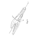
図1は耕作機械に取り付けるための磨耗または交換可能部品用の本発明に係る磨耗部品システムの部品の略組立分解斜視図であり、該磨耗部品システムの連結部品は、交換可能な爪先の形の前磨耗部品と、特定のツールに固定するための後ホルダ部品と、ロック装置を介する共通ロック機構を有する、前記部品のための連結システムとを備えており、連結形状を示すべく全部品が座標軸と共に図示されている。
図2は上前方から斜めに見た、図1に係るホルダ部品の部分の略斜視図である。
図3は上前方から斜めに見た、図1に係る磨耗部品の部分の略斜視図である。
図4aは上後方から斜めに見た、図1に係る磨耗部品の部分の略斜視図である。
図4bは後方から見た、図1に係る磨耗部品の部分の略端面図である。
図5は磨耗部品システムの一部を形成し、一つに合わせて図1に係る爪の形の耕耘装置を形成する、連結部品の部分を上部前方から斜めに見た略斜視図である。
図6は側方から斜めに見た、図5に係る組み立てられた連結部品の略斜視図である。
図7は側方から見た図5に係る組み立てられた連結部品の略側面図であり、特に、磨耗およびホルダ部品それぞれのカラー間の初期遊び、および連結部品の両側でカラーの間に配置された共通サイドジョイントの好適な位置を示し、該サイドジョイントは、突起およびこの突起と相互作用する凹所を備え、かつ相互に正対して配置されZ軸を中心に半径方向に配設された異なる半径の二つの端面を有する。
図8は上から見た図1に係る組み立てられた連結部品の部分の略上面図である。
図9は下から見た図1に係る組み立てられた連結部品の部分の略底面図である。
図10は前から見た図1に係る組み立てられた連結部品の部分の略正面図である。
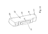
図11は前上方から斜めに見た、図1に示すロック装置の部分の略斜視図であり、ロック装置の圧縮板を明瞭に示し、かつロック装置がY方向およびZ方向の両方で非常に非対称であることを明瞭に示す。
図12は図7に係る組み立てられた連結部品の部分の略垂直長手方向断面図である。
図13はロック装置開口内に導入されたロック装置の断面を明瞭に示す、図7に係る組み立てられた連結部品の部分の略水平長手方向断面図であり、該断面図は、エラストマの形のロック素子の膨張用に意図されたロック装置本体の側方ギャップ開口、ロック本体の前面および背面それぞれに配置された圧縮板および固定板を示す。
図14は1〜4は、組み立てられたばかりの爪から非常に磨耗してサイドジョイントが使用され始めた爪までの磨耗の経過を概略的に示す。磨耗部品の特定の部分は、磨耗過程をよりよく示すために切り欠かれている。
図15a〜dは、後方から見た、図7に係る組み立てられた連結部品の部分の略断面図を示す。
図16はロック装置の上部と磨耗部品のカラーを貫通する上部ロック装置開口とを備えたロック機構の拡大詳細図を示す。
DESCRIPTION OF THE DRAWINGS The present invention will now be described in further detail with reference to the accompanying drawings.
FIG. 1 is a schematic exploded perspective view of a part of a wear part system according to the invention for a wear or replaceable part for attachment to a farming machine, the connecting part of the wear part system being in the form of a replaceable toe. A pre-wear part, a rear holder part for fixing to a specific tool, and a connection system for said part with a common locking mechanism via a locking device, all parts being coordinate axes to show the connection shape It is shown in FIG.
FIG. 2 is a schematic perspective view of a portion of the holder part according to FIG.
FIG. 3 is a schematic perspective view of a portion of the wear part according to FIG. 1 as viewed obliquely from above and forward.
FIG. 4a is a schematic perspective view of the part of the wear part according to FIG.
FIG. 4b is a schematic end view of the part of the wear part according to FIG.
FIG. 5 is a schematic perspective view of a part of the connecting part forming a part of the wear part system and forming a claw-shaped tillage device according to FIG.
FIG. 6 is a schematic perspective view of the assembled connecting part according to FIG. 5 as viewed obliquely from the side.
FIG. 7 is a schematic side view of the assembled connecting part according to FIG. 5 as viewed from the side, in particular the initial play between the collars of the wear and holder parts, respectively, and between the collars on both sides of the connecting part. A common position of the common side joint, the side joint being provided with a protrusion and a recess interacting with the protrusion and arranged opposite to each other and arranged radially about the Z axis. It has two end faces of radius.
FIG. 8 is a schematic top view of the part of the assembled connecting part according to FIG. 1 as viewed from above.
FIG. 9 is a schematic bottom view of the part of the assembled connecting part according to FIG. 1 as viewed from below.
10 is a schematic front view of the assembled connecting part according to FIG.
11 is a schematic perspective view of the portion of the locking device shown in FIG. 1 as viewed obliquely from the front upper side, clearly showing the compression plate of the locking device, and the locking device is very much in both the Y and Z directions. Clearly show asymmetry.
12 is a schematic vertical longitudinal sectional view of the assembled connecting part according to FIG.
FIG. 13 is a schematic horizontal longitudinal section of the part of the assembled connecting part according to FIG. 7 clearly showing the section of the locking device introduced into the locking device opening, the sectional view being in the form of an elastomer Fig. 4 shows a side gap opening of the locking device body intended for expansion of the locking element, a compression plate and a fixing plate arranged respectively on the front and back surfaces of the locking body.
FIG. 14 shows schematically the course of wear 1-4 from the just assembled nail to the nail where it has become very worn and the side joint has begun to be used. Certain parts of the wear parts are cut away to better show the wear process.
15a-d show a schematic cross-sectional view of the part of the assembled connecting part according to FIG. 7 as seen from the rear.
FIG. 16 shows an enlarged detail view of the locking mechanism with the upper portion of the locking device and the upper locking device opening through the collar of the wear part.
図1を参照すると、本発明の好適な実施形態に係る磨耗部品システム1の部品が概略的に示されており、該磨耗部品システム1は、耕作機械のツールに交換可能な磨耗および/または交換部品2を、さらに詳しくはここでは機械(詳細には図示せず)のバケット上の爪を、着脱自在に取り付けるように意図されている。
Referring to FIG. 1, there is schematically shown the parts of a
以下で詳述する本発明は主として、言うまでもなく、消費するように、つまり磨耗するように意図された部品に関するが、特定のツールの用途に関係する様々な機能を持ったどんな交換可能な作業部品も本発明の概念内である。しかし、以下では、爪を含む実施形態について本発明を詳述するだけである。 The invention described in detail below primarily relates to parts intended to be consumed, i.e. worn, but any replaceable work part with various functions related to the particular tool application. Are also within the concept of the present invention. However, in the following, the invention will only be described in detail with respect to an embodiment including a nail.
磨耗部品システム1は図1に、下述する力、部品、および細部の相互の位置および相互に対する大きさを示すために、三つの座標軸X、Y、Zを含む共座標系と共に示される。図示する座標系に従って作用荷重(F)がもたらす分力Fx、Fy、およびFzについては、上で詳細に説明した。
A
磨耗部品システム1は、二つの主要な相互に作用する連結部品2、3を含む。一方では、交換可能な爪先の形の前部磨耗部品2、他方では特定のツール(詳細は図示せず)に永久固定するための後部静止ホルダ部品3である。
The
交換可能な爪先2のホルダ3への動的でしかも依然として確実な固定を達成するために、磨耗部品システム1は、前記連結部品2、3に共通する着脱自在の連結システム4をも含み、該システムは、特徴的な連結形状4および着脱自在のロック機構5を有し、フードシステムとも呼ばれる。全ての軸力Fyがそれに沿ってまたはそれと平行に作用すると考えられる、連結形状4のY方向の対称線は、図1および図5〜9に最も良く示される。
In order to achieve a dynamic and yet secure fixing of the
第一の前部連結部品2(便宜的に図3参照)は、かなり大きい中空7を含む後部セグメント6を備えている。特に図4aを参照されたい。該中空は、フード6のように、対向する第二連結部品3の全ての外側面の周囲、前端部8を実質的に覆うように意図され、該前端部はY方向にテーパが付けられ、つまりくさび形またはビーク形である。図2参照。
The first front connection piece 2 (for convenience, see FIG. 3) comprises a
フード6およびビーク8は、直接または特定量の磨耗後に相互に作用する、複数の特別に構成された表面ゾーン9を含む。特に、図12、13、14、および15を参照されたい。各々のそのような表面ゾーン9は、少なくとも二つの相互に対向しかつ相互作用する接触面10または非接触面11を含む。図2および4を参照されたい。そのうちの少なくとも一つは、第一連結部品2に配置され、もう一つは第二連結部品3に配置される。
The
位置に応じて例えば基本的に平坦、凹、または凸形状等とすることのできる接触面10は、本発明に特徴的な連結形状4を形成するために、相互に対し、かつ座標系に対して様々な傾斜、大きさ、および位置を持って構成される誘導面、滑り面、摩擦面、または止め面10を含む。接触面10はここで、連結部品2、3の取付け直後に、または特定の表面10の特定の定められた磨耗後に、相互作用状態で相互に支え合うように、または支え合うようになるように設計される。前記表面ゾーン9および接触面10の幾つかの特定の特性および位置については以下でさらに詳述する。
Depending on the position, the contact surfaces 10, which can be basically flat, concave, convex or the like, are relative to each other and to the coordinate system in order to form a
ここに示す実施形態では、ホルダ3の後部12は、ビーク8から後方に突出する二つの対向する係合脚13、14を含む。図2を参照されたい。該係合脚は、固定ジョイントによって基本的に永久に、例えば溶接ジョイントまたはボルトジョイント(図示せず)によって、図に示す実施例では、ツール(図示せず)の作動前縁の両側の溶接ジョイントによって、特定のツールに固定されるように意図されている。
In the embodiment shown here, the
以下で爪カラー15と呼ぶフード6の自由外周セグメント15は、爪カラー15と対向しかつそれと相互作用するセグメント16によって対応付けられる。図4a〜4bを参照されたい。以下でビークカラー16と呼ぶ後者のセグメントは、ホルダ3上に配置される。図2を参照されたい。各カラー15、16は基本的に垂直に配置された縁または端面17、18を含み、該端面17、18は相互に対向する。
The
変化する誘導面、滑り面、摩擦面、または止め面10および少なくとも最初は爪部品2と接触しない特定の非接触面11を含む二つの連結形状4は、一方では後部連結部品3のビーク8の外側に、ビークカラー16の端面18に沿って配置されて、この連結部品3の外部連結形状4を形成し、他方ではフード6の内側の前部連結部品2の内側に、爪カラー15の端面17に沿って配置されて、内部連結形状4を形成する。該表面10、11は相互作用して前記着脱自在の連結システム4を形成する。
The two connecting
側面半径、二次止め面:
ホルダ部品3の両側で、つまり上記座標系による垂直長手方向対称面(XY)と基本的に平行に配設されるように図2に示された側面で、磨耗部品2の方向つまりその前縁の方向を向いたビークカラー16の端面18から、特定の定められた半径20の側面垂直突起19は、爪部品2の方向に突出するように構成される。
Side radius, secondary stop surface:
The direction of the
二つの突起19は、フード6の外周の両側で、これらに正対して配置されかつ爪カラー15の端面17につまりその後縁に(便宜的に図4a〜4b参照)形成された、二つの凹所21によって対応付けられる。どちらの凹所21も、連結部品2、3が一つに連結されて二つの側部ロータリジョイント22、23が生成され、凹所21および突起19が遊び24を介して小さい距離を開けて配設された直後に、突起19と相互作用するように設計され、よって特定の定められた接触面10の特定の定められた磨耗が、好ましくは問題の接触面10に対する特定の相互磨耗順で生じた後でのみ、前記相互作用は発生する。特に図14:1を参照されたい。
The two
図14:1に係る組み立てられた連結部品2、3の略側面図は、磨耗部品およびホルダ部品2、3それぞれのカラー15、16間の初期遊び24、および連結部品2、3の両側でカラー15、16の間に配置された二つの共通サイドジョイント22の一つの好適な位置を示す。該サイドジョイントは、相互に正対して配置され、かつ基本的にZ軸を中心に半径方向に配設され(図4bおよび図2参照)、かつ相互に異なる半径R1、R2を有する二つの端面25、26を含む。図14:1を参照されたい。
14: 1 shows a schematic side view of the assembled connecting
それぞれの凹所21の半径R1は、対応する突起19の半径R2より多少大きいことが好ましく、それは、離間距離つまり遊び24が選択された半径によって変化し、かつこれらの湾曲した端面25、26間の接触が主として水平面(YZ)内の異なる半径R1、R2の共通中心で、つまりビークカラー16の端面18から最も大きく外に突出する突起19のその点M0で行なわれるので、特定の定められた磨耗後に、この中間接触点を中心に対称的に半径方向の接触ゾーン22’、23’へと成長し、したがって磨耗が進行するにつれてそれは基本的にトルク原点M0を構成するという効果を持つ。図14:2を参照されたい。
The radius R 1 of each
それぞれのカラー15、16の相互に対面する端面25、26間の連結部品2、3に共通する、基本的に予め定められた半径方向の接触ゾーン、つまり連結部品2、3の両側にその中間接触点M0を中心にこうして形成されたジョイント22、23であって、その中間接触点M0を中心にして、かつその接触ゾーンに沿って、それぞれ爪部品2およびホルダ部品3が荷重の伝達を随伴しながら動的に相互作用するように設計されて成るジョイントの結果、それらの間の遊び24はかなり大きいので、爪およびホルダカラー15、16の残部は通常離れたままになる。これは、前記端面25、26間のその目的で作られた接触ゾーン22、23の外側のカラー15、16間の磨耗を防止する。
An essentially predetermined radial contact zone common to the connecting
本構成は、好ましくない二次接触ゾーンの危険性、およびしたがって不利なてこ率が爪部品2およびホルダ部品3の間の垂直端面17、18に沿ったどこか別の場所で発生する可能性を防止するか、少なくとも最小化する。それにより、不都合な剪断力による上述した問題の発生の可能性も回避される。
This configuration eliminates the risk of undesirable secondary contact zones and thus the possibility of unfavorable leverage occurring elsewhere along the vertical end faces 17, 18 between the
ロック機構:
ロック機構5は、ロック装置27(図11参照)と、磨耗部品システム1の長手方向Yに対し直角に、かつ基本的にビーク8ならびにフード6の二つの相互に対向する上壁6’および下壁6”の両方を垂直に貫通して走り、その中にロック装置27が挿入されるように意図されたロック装置開口28とを含む。図2ならびに図3および4に加えて図12を参照されたい。
Lock mechanism:
The
三部分ロック機構:
ロック装置27の本体29およびロック装置開口28は、複数の大きさが異なるが相互に平行な断面部分を含む。図11および12を参照されたい。それらは、ロック装置本体29の場合、ロック装置27の導入の方向に、最小部分29Cを下方に、最大部分29Aを最上部に配置され、それは爪部品2の上部6’および下部フード壁6”を貫通するロック装置開口28の断面にも当てはまる。つまり、上部開口28Aは下部開口28Cより大きい。
Three-part locking mechanism:
The
ロック装置本体29およびロック装置開口28は、爪部品2のフード6を貫通するロック装置開口28Aおよび28Cの断面、ならびにロック装置本体29の断面29Aおよび29Cが、各部分の位置が対応する場合、必要な許容差を別として、同一であるように設計される。つまり、これらの断面セグメントはうまく一つに嵌合する。鋼製であることが好ましい剛性ロック装置本体29は機械的スペーサとして働き、それにより爪部品2がホルダ部品3から引き抜かれ/落下することが防止される。
When the lock device
ロック装置27は、ロック装置本体29に加えて、ロック装置本体29の連続ギャップ開口41、42を介して作用するように設計された多数の可動係合部30、31を含む。図11および12を参照されたい。該ギャップ開口については以下でさらに詳述する。また、以下でさらに詳述する、圧縮後のエラストマ32の膨張用のさらなる連続ギャップ開口44を有する、ロック本体29内部の中空43に配設された弾性要素32(図12および13参照)を含む。弾性要素32は、係合部品30、31に対して作用する弾性力を発生するように意図され、それによりこれらは、それらの外側延長位置に向かって押圧される。図示した実施形態では、係合部品30、31は、二つの金属製の基本的に垂直に配設された板30、31によって構成され、該板30、31は、一方では前部圧縮板30および後部固定板31によって構成される。これらの板31、32は適切な方法で弾性要素32に固定され、あるいは板31、32は、前記開口41、42から落下することができるのを防止する装置または断面を含む。図12を参照されたい。
In addition to the
図13は、ロック装置27およびロック装置開口28を通る、つまり基本的に圧縮板30の真ん中の高さの水平面(YZ)の下からの断面図を示す。ビーク8を貫通するロック装置開口28Bの正面には、図示した実施形態では、圧縮板30を受容するように意図された前部キャビティ33がある。ビーク8を貫通するロック装置開口28Bは、ロック装置27の後側全体に沿って、後部キャビティ34をも含む(図12参照)。つまり、ビーク8を貫通するロック装置開口28の断面28Bは、ロック装置本体29の対応する断面29Bの場合より、Y方向に大きい。ビーク8を貫通する前記ロック装置開口28Bの後側には後向きの傾斜ベベル35が形成され、それによって開口28Bの断面の幅はY方向に、フードルーフ36つまりフード6の上部内側に向かって上向きに徐々に増大する。図16を参照されたい。後部キャビティ34のこの上部35は、固定板31用に意図されている。弾性要素32によって完全に延長された圧縮板30をも含めて、大きさは大きさ29Aより便宜的に多少小さく、それによって弾性要素32は、爪部品2をホルダ部品3に押し上げられた位置に保持すると同時に、ロック装置27がロック装置開口28のその位置から落下するのを防止するように設計された、特定のプレテンションを生成する。他方、ビーク8を貫通するロック装置開口28の断面28Bは、フード6を貫通する二つの開口28A、28Cより大きいかもしれず、主なポイントは、後部空き空間が形成されるので、ロック装置本体29とビーク8を貫通するロック装置開口28Bとの間の部分に接触が存在しないことである。よってこの部分の磨耗の可能性は排除される。
FIG. 13 shows a cross-sectional view from below the horizontal plane (YZ) through the locking
さらに、上述したロック装置27の異なるサイズで連続的に拡大する部分29A、B、およびC、ならびにロック装置開口28の28Aおよび28Cの結果、ロック装置27をそれがハンマを必要とするより大きい部分または突起板30、31まで来る前に、その長さの約半分まで挿入することができ、かつロック装置27は、導入の最後の押下げ部分中に、手動的に保持する必要が無いという、求められている利点が達成される。
In addition, as a result of the
達成されるさらなる利点は、ロック装置開口28の最上部の最大断面28Aがロック装置の作動ロック位置にある一方または他方の板30、31の最大断面よりわずかに大きく構成されるので、磨耗部品システム1が作動する準備が整ったときに弾性要素32が受ける圧縮と比較して、その実際の取付けおよび取外し中に、弾性要素32をかなり高度に圧縮する必要が無いことである。さらに、弾性要素32は、十分に大きいプレテンション距離を得るために過圧縮する必要が無く、動作位置にある弾性要素32の動的経路を全部利用することができる。ロック装置の板30、31が、取付け/取外しの過程で、フード6を貫通するロック装置開口28Aの壁を著しく摩擦せず、かつ動作中に、ビーク8を貫通するロック装置開口28Bの壁を摩擦しないという事実は、板30、31および壁28Bが摩滅する危険性が低いことを意味する。ロック装置の板30、31が動作中にロック装置開口28Bの壁を著しく摩擦しない主な理由は、後部キャビティ34のおかげで、ロック装置27がホルダ部品3に対するY方向のその運動に磨耗および/または交換部品2を比較的自由に随伴するという事実である。該運動は代わりに、磨耗部品システム1の接触ゾーン9によって制限される。基本的に実際の動作によって生じる軸方向の力Fyはロック装置27によって吸収しなければならないので、したがって、例えばロック装置27の取外しを容易にするために、キャビティ33を省き、圧縮板30を開口28Bの壁に直接作用させることが考えられる。図12の破線を参照されたい。ロック装置27の主な機能は、前に述べた通り、爪部品2をホルダ部品3上に押し上げられた位置に保持すると同時に、固定板31を介して、ロック装置27がロック装置開口28内のその位置から落下するのを防止することである。
A further advantage to be achieved is that the
ロック機構用の切欠き:
ビーク8を貫通するロック装置開口28Bは、ロック装置開口28の前記部分28Bの片側に作られた第二傾斜ベベルをも含み、該傾斜ベベル37の結果、開口28BのZ方向の断面幅は、フードルーフ36の底面に向かって上向きに徐々に増加する。図15bを参照されたい。フード6を貫通する上部ロック装置開口28Aはまた、一つの側方の基本的に垂直方向の余分のベベル38をも含み、該ベベル38はロック装置開口28Bの前記側方傾斜ベベル37の延長を構成する。
Notch for locking mechanism:
The locking device opening 28B penetrating the
それに相応して、ロック装置27は、上部側方垂直ショルダ39の形のZ方向の断面の増大を含む。図1を参照されたい。該ショルダ39は、必要な許容差を除いて、前記側方垂直ベベル38と同一形状を有する。(図15bの断面は、ロック装置27の下部29Cおよびショルダ39が見えないように選択されていることに注意されたい)。他方、ロック装置27は好ましくは、フードルーフ36の内側から、ロック装置本体29の片側に作られた基本的に上述したギャップ開口44の上縁まで、空き空間40が存在するように、Z方向のロック装置開口28Bの側方傾斜ベベル37に対応するショルダ無しにすることができる。図15bを参照されたい。該ギャップ開口44は、ロック装置27の取外しに関連したエラストマの圧縮後のエラストマ32の膨張用に意図されたものである。しかし、この種のさらなるショルダがあっても、以下でさらに詳述する機能のみならず、結果も基本的に同じである。
Correspondingly, the locking
したがってロック装置27およびロック装置開口28は、爪部品のフード6を貫通するロック装置開口28A、28Cの断面、およびロック本体29A、29Cの断面が、各部分の位置が対応する場合、必要な許容差を別として、同一であるように設計される。つまり、これらの断面セグメントはうまく一つに嵌合する。図8〜10および12を参照されたい。したがって、塵埃の侵入はかなり難しくなるが、前記許容差のため、依然として完全には解消されず、その結果、ロック装置開口28Bの傾斜ベベル37によって形成されるロック装置27の片側に沿った空き空間40には、塵埃が充満するおそれがある。
Accordingly, the
本発明は、ロック装置27が取り外されるときに、それがX方向に特定の距離だけ押し上げられる一方、板30、31の圧入によるゴム32の圧縮が、ギャップ開口44によって可能となる方向にのみエラストマ32を非対称的に側方に膨張させ、ロック装置27の様々な断面29A、および29Bおよび29Cそれぞれならびにロック装置開口28の対応する断面の間のZ方向の大きさの相違のおかげで、空き空間40が絶えず上向きに変位するという事実によって、この塵埃の問題を解決した。これの効果は、板30、31の圧入によって引き起こされるエラストマ32の膨張部分が常に、常に空き空間40内に移動することができ、それによって絶えず開き空間が上向きに形成されることである。ロック装置27がこの初期空き空間40に対応する上述の追加ショルダをも含む場合、ロック装置27はロック装置開口28から上向きに押し上げられるので、空き空間40は依然として形成される。したがって、ロック装置27の取外しは基本的に、全ての塵埃の侵入に無関係である。
The invention provides that when the
ピンおよび剪断ゾーンの再配置
爪部品2のフード6を貫通する上部の大きいロック装置開口28Aに続いて、フードルーフ36の内側に配置された下方に突出する側方ピン45があり、それに当ててロック装置27の後部固定板31が固定される。図16を参照されたい。これは、固定板31を下方に移動させることができるので、板31がその中で動作する開口35、42がこうして爪部品2とホルダ部品3との間の直接剪断ゾーンから変位するという利点をもたらす。ロック装置本体29の後部に前記ピン45の方向に向けて形成された、下方に広がったベベル46のおかげで、ロック装置本体29およびピン45が相互接触しない結果として、該剪断ゾーンはさらに多少上向きに変位している。実際非常に重要なさらなる利点は、固定板31が下方に移動するときに、エラストマ32用の中空43もまた下方に移動することができ、よって剪断荷重が、ロック装置27の中実本体29の事実上均質な断面に沿って吸収されることである。ロック装置27の強度をさらに高めるために、エラストマ32の膨張用のロック本体29の開口44を、ロック本体の片方の側面にだけ形成する。図13を参照されたい。
Pin and Shear Zone Relocation Following the upper large locking device opening 28A through the
連結システムの表面ゾーン:
爪に対して作用する各荷重(F)は、ホルダ部品3内または上に配置された相互に対向しかつ初期に相互作用する接触面10、および前記ホルダ部品と相互作用する磨耗部品2内または上の他の接触面10を含むが、動作の開始時には接触せず特定の磨耗後に相互に接触するようになる幾つかの表面11をも含む、上述した特別に構成され相互に作用する表面ゾーン9を介して、連結形状4によって吸収される。
Linkage system surface zone:
Each load (F) acting on the claw is located in or on the
爪部品2に加えられる垂直方向の力Fxは、一方では、力Fxが作用する爪の側によって決定される二つの前部の平坦な水平接触ゾーン9a、9b(図12および15d参照)のうちの一つを介して、他方では、後縁で、水平対称面YZで見て、前記前部の水平接触ゾーン9a、9bの反対側で、ロック装置開口28および長手方向対称軸Yに対して対称でありかつ水平対称面YZに対して傾斜している二つの後部接触ゾーン9cおよび9dを介して、連結形状4によって吸収される。図12および15aを参照されたい。該ゾーン9c、9dの基本的に水平方向の限界線は、断面が磨耗およびホルダ部品2、3それぞれを通る断面が描かれる場合、この場合、基本的に「矩形−楕円形」の断面の丸みを付けた隅9fの間の部分を構成する。図15a〜15dを参照されたい。後部接触ゾーン9c、9dはそれぞれの外周側縁ゾーン9g、9hに移行し、それは前部接触ゾーンの側縁ゾーン9i、9jと平行であり(図13、15a、および15d参照)、それはY対称線と平行とすることができるが、それに対してわずかに傾斜することが好ましい。
The vertical force F x applied to the
同様に、爪先2に加えられる側方の力Fzは、連結形状4の前部の平坦な側縁ゾーン9i、9jの対の一つによって、および垂直対称面XZで見て前記前部側縁ゾーン9i、9jの特定の対の反対側の後縁では、長手方向対称軸Yに対して、二つの対称な後部の基本的に垂直な側縁ゾーン9g、9hの対によって吸収され、該側縁ゾーン9g、9h、9i、9jの外周線は、磨耗およびホルダ部品2、3それぞれを通る断面が描かれる場合、本書では基本的に「矩形−楕円形」断面の垂直縁を構成する。
Similarly, the lateral force F z applied to the
軸方向の力Fyは上述した方法で、便宜的に前記長手方向対称線Yに対し略垂直に配置され、機能が基本的に同一となるような、つまり基本的に垂直断面(XZ)内に配置されまたはそこに作用する上述した外部および内部止め面と同様に機能するような、大きさの半径R1、R2、または傾きを持つ、各々少なくとも二つの対向しかつ相互作用する接触面10e、10e’、25、26で構成される、一つまたはそれ以上の接触ゾーン9e、22、23を介して、上述した方法で吸収される。図13を参照されたい。ここで一つの接触面10e、26はホルダ部品3上に配置され、他方の接触面10e’、25は磨耗部品2上には位置される。しかし、より広範な磨耗後、爪部品2とホルダ部品3との間の滑りゾーンとして働く、特定の当初非接触の表面11および大きく傾斜した表面、つまり特定のくさび効果を持ちまたは獲得した表面もまた、荷重の特定部分を吸収することができる。しかし、理想は、磨耗部品2の同様に垂直な内側10e’に当てたビーク8の垂直前縁10eによる略垂直な接触ゾーン9eおよび半径方向の接触ゾーン22、23、磨耗部品2の凹所21上にZ軸を中心に半径方向に配設された端面25、ならびにホルダ部品3の突起19上にZ軸を中心に半径方向に配設された端面26が、基本的に全ての軸方向の荷重Fy、およびしたがって基本的に全ての磨耗を吸収することである。図4bを参照されたい。
The axial force F y is, for convenience, arranged substantially perpendicular to the longitudinal symmetry line Y and has basically the same function, that is, basically in the vertical section (XZ). At least two opposing and interacting contact surfaces each having a radius R 1 , R 2 , or inclination of magnitude such that they function in a manner similar to the above described external and internal stop surfaces disposed on or acting on It is absorbed in the manner described above via one or
磨耗するように設計された当初垂直な止め面10e、10e’、および「半径方向の垂直な」止め面25、26の磨耗が増大するにつれて、必然的な二次接触ゾーン22’が形成され(図14:4参照)、徐々に、しかし今は特定の予め定められたより大きい磨耗、およびより長時間の使用後に初めて、かつその後、結局、内部止めゾーン9e、二つの側方ロータリジョイント22、23、およびより大きく傾斜した接触ゾーン9で非常に大きく、またはごくわずかに成長するが、以前のように、ほとんどの部分に対し制御不能に、かつ磨耗部品2の爪カラー15の後縁17とホルダ3のカラー16の前縁18との間の変化するてこ率に関して非常に不利な位置では、成長することはない。
As the wear of the initially vertical stop surfaces 10e, 10e 'and the "radially vertical" stop surfaces 25, 26 designed to wear increases, an inevitable secondary contact zone 22' is formed ( FIG. 14: 4), but gradually, now only after a certain predetermined greater wear, and after a longer period of use, and then eventually the internal stop zone 9e, the two lateral rotary joints 22, 23 , And grows very large or very slightly in the more
前部の対を成す垂直側部および水平接触ゾーン9i、9jおよび9a、9bはそれぞれ、ホルダ3のノーズ8を通過するY対称線と事実上平行な大きさを有する。二つの隣接する前側部間の各々の共通する長手方向の「丸みを付けた」縁9fおよびそれぞれの水平接触ゾーン9i、9jおよび9a、9b、ならびに中間外周線は、前記後部の対を成す垂直側部および水平接触ゾーン9g、9h、および9c、9dそれぞれの各想像断面の対応する縁および外周線と平行に配設される。爪2がホルダノーズ8から滑り落ちる上述した傾向は、それによっていわゆる引出し効果の模倣を通して効果的に克服される。つまり、ホルダ部品3と爪部品2との間の特定の接触面10がジャミングし、それによって部品2、3を一つに合わせて固定する。
The front side vertical side and horizontal contact zones 9i, 9j and 9a, 9b each have a size substantially parallel to the Y symmetry line passing through the
分力Fx、Fy、およびFzが引き起こすトルク荷重は主に、上記に従って生じる回転の中心軸のいずれかの側の前部接触ゾーンの一つおよび後部接触ゾーン9の一つを介して吸収される。動作中に、一体的接触面10、主として止め面10e、10e’、25,26はしたがって、磨耗部品2、ホルダ部品3、およびロック装置27の間の不規則な動的運動中に、剪断、磨耗、および変形するが、爪部品2は外部磨耗のために、実質的にずっと大きく磨耗し、その結果、長い時間をかけて、ホルダ部品3の交換も必要になる前に、この部分2だけを交換しなければならない。これは、材料コストおよびダウンタイムが大きく削減され、非常に有利であることを意味する。
The torque loads caused by the component forces F x , F y and F z are mainly via one of the front contact zones and one of the
本発明に係る突起19および凹所21は少なくとも初期には、従来非常に厄介であった望ましくないてこ比および非対称な磨耗を解消するので、システムのカラー間の接触は長い時間をかけて、この目的のために設計された位置つまり原点M0のみで発生するため、磨耗部品システム1が回転荷重に暴露されたときにロック装置27を強力に切断する剪断力が最小化される。
The
したがって、ロック装置27と組み合わせされた二次止めゾーンの位置は、意図された前部および後部水平および側方接触面10に取って代わらない。考えられるあらゆる荷重の事例に対し、強度にとって非常に有利なトルクレバレッジが常に得られる。該レバレッジは、構造物にとって深刻ないかなる剪断力をも引き起こさない。さらに、ホルダ部品3と磨耗部品2との間の摺動ゾーンで依然として発生するこれらの剪断力は、ロック本体29A、29Cの均質部分だけのほとんど切れ目のない断面のみで作用する。
Thus, the position of the secondary stop zone in combination with the locking
代替実施形態
本発明は図示した実施形態に限定されず、本発明の請求項の範囲内で様々に変形することができる。
Alternative Embodiments The present invention is not limited to the illustrated embodiments, and can be variously modified within the scope of the claims of the present invention.
本特許出願の図では、例えば、ホルダ部品3の前部「連結部分」は前記ビーク8を構成し、それは爪部品2の後部「連結部品」によって覆われる。したがって、後者の連結部品はフード6を構成する。フードとビークの対向関係が言うまでもなく考えられることは理解されるであろう。したがって、凹所21および突起19の相互位置を交換して、代わりに突起を磨耗部品2のカラー15上に配置することは、本発明の概念の範囲内であり、その逆も然りである。しかし、この場合、上記の交換は損なわれる。
In the figure of this patent application, for example, the front “connecting part” of the
さらに図に示す実施形態では、突起19は、ビークカラー16から磨耗部品2の方向に半径方向に突出する二つの基本的に半円形の延長によって構成される。該突起19は、爪部品2のフード6内の対向接触面25に形成された基本的に半円形の陥凹によって対応付けられる。二つの相互作用する規則的な半円形の半径R1、R2を含む代わりに、凹所21および突起19の実現は、基本的に水平面XY内の中心軸を中心とする特定の回転性が、すなわち小さいてこ率で維持される限り、多少段状の「角ばった」凹形および凸形を持つ実現によって構成することができるはずである。
Furthermore, in the embodiment shown in the figure, the
主なポイントは、磨耗にも拘わらず、結果的に得られるてこ率が、例えばトルクレバレッジができるだけ短いおかげで、機能および実際のロックに対してできるだけ有利であることである。これは、前記凹所21および突起19の接触ゾーン22、23の間の接触点つまり原点M0が、基本的に水平面(YZ)内に、Y対称線に沿って側面XYに平行に存在することを意味する。
The main point is that despite the wear, the resulting leverage is as advantageous as possible for function and actual locking, for example thanks to as short a torque leverage as possible. This contact point, i.e. the origin M 0 between the
連結形状4の部分を形成する表面10、11の数、大きさ、傾斜、配置、表面構造、および形状は、任意の時に磨耗部品システム1および特定の機器またはツールに対して得られる特性および要件に合わせて調整され、その結果、表面10、11に関する全ての他の構成が本発明の概念の範囲内に該当することは理解されるであろう。
The number, size, slope, arrangement, surface structure, and shape of the
Claims (15)
− 磨耗部品システムの長手方向対称線Yの両側に配置される少なくとも一対の第一前部接触ゾーン(9a,9b)、および前記対称線に対しその両側で定義された角度を成す少なくとも一対の第一後部接触ゾーン(9c,9d);
− 横方向に対を成してずらして、対称線Yの両側に配置された少なくとも一対の第二前部および後部接触ゾーン(9i,9j及び9g,9h);
− 少なくとも一つの第三前部接触ゾーン(9e)および少なくとも二つの第三後部接触ゾーンを含む第三接触ゾーン
を備え、少なくとも二つの第三後部接触ゾーンのうちの二つは、共通回転軸線Zを有する、相互作用するジョイント(22,23)によって構成され、該ジョイント(22,23)は各々、凹所(21)および突起(19)を備え、各凹所および突起は、それぞれの端部接触面(25,26)を含み、各ジョイントの凹所および突起の一方は、ホルダ部品(3)上に配置されており、各ジョイントの凹所および突起の他方は、磨耗および/または交換部品(2)上に配置されている磨耗部品システムにおいて、
前記凹所および突起のそれぞれの端部接触面(25,26)は相互作用して、磨耗および/または交換部品(2)のホルダ部品(3)に対する押し込みを制限し、それぞれの端部接触面(25,26)間の接触が第一に前記それぞれの端部接触面(25,26)の中間接触点M0に形成され、かつ第二に、磨耗部品システム(1)の磨耗が進むにつれて、この中間接触点M0を中心に、大きな接触ゾーンにわたってますます形成されるように設計されることを特徴とする磨耗部品システム(1)。A holder part (3) for attachment to a tool and comprising a holder beak (8) and a wear and / or replacement part (2) disposed on the holder beak and comprising a hollow (7), Wear part system (1) intended for tools of earthworking machines, the hollow (7) is designed to grip the holder beak (8) and the holder part (3) and wear and / or exchange Secured to the holder part (3) by means of a locking mechanism (5) through the part (2), the holder beak (8) and the hollow (7) of the wear and / or replacement part (2) have a contact zone (9) Each contact zone has at least two interacting contact surfaces (10, 25, 26), one of the at least two interacting contact surfaces being arranged on the holder part (3). The other of the at least two interacting contact surfaces is arranged on the wear and / or replacement part (2), the interacting contact surface is intended to absorb force and contact Zone (9)
-At least a pair of first front contact zones (9a, 9b) arranged on either side of the longitudinal symmetry line Y of the wear part system, and at least a pair of second forming an angle defined on both sides of said symmetry line; One rear contact zone (9c, 9d);
-At least a pair of second front and rear contact zones (9i, 9j and 9g, 9h) arranged on opposite sides of the symmetry line Y, shifted in pairs in the lateral direction;
-A third contact zone comprising at least one third front contact zone (9e) and at least two third rear contact zones, wherein two of the at least two third rear contact zones have a common axis of rotation Z Each having a recess (21) and a protrusion (19), each recess and protrusion having a respective end. Including contact surfaces (25, 26), one of the recesses and protrusions of each joint being arranged on the holder part (3), the other of the recesses and protrusions of each joint being a wear and / or replacement part (2) In the wear parts system arranged above,
The respective end contact surfaces (25, 26) of the recesses and protrusions interact to limit wear and / or pushing of the replacement part (2) against the holder part (3), and the respective end contact surfaces. (25, 26) contact between is formed on the intermediate contact point M 0 of the respective end contact surfaces in the first (25, 26), and secondly, as the wear of the wear parts system (1) proceeds , wear parts system, characterized in that the intermediate contact point M 0 in the center, are designed to be increasingly formed over a large contact zone (1).
Applications Claiming Priority (2)
| Application Number | Priority Date | Filing Date | Title |
|---|---|---|---|
| SE0203856A SE522438C2 (en) | 2002-12-23 | 2002-12-23 | Wear part system for detachable mounting of wear parts to a soil preparation machine tool |
| PCT/SE2003/002021 WO2004057117A1 (en) | 2002-12-23 | 2003-12-19 | Wearring parts system for detachable fitting of wearing parts for the tool of a cultivating machine |
Publications (3)
| Publication Number | Publication Date |
|---|---|
| JP2006511741A JP2006511741A (en) | 2006-04-06 |
| JP2006511741A5 JP2006511741A5 (en) | 2007-01-25 |
| JP4481833B2 true JP4481833B2 (en) | 2010-06-16 |
Family
ID=20290003
Family Applications (1)
| Application Number | Title | Priority Date | Filing Date |
|---|---|---|---|
| JP2004562213A Expired - Fee Related JP4481833B2 (en) | 2002-12-23 | 2003-12-19 | Wear parts system for removably attaching wear parts for tools in farming machines |
Country Status (32)
| Country | Link |
|---|---|
| US (1) | US7703224B2 (en) |
| EP (1) | EP1590534B1 (en) |
| JP (1) | JP4481833B2 (en) |
| KR (1) | KR101063369B1 (en) |
| CN (1) | CN1748063B (en) |
| AU (1) | AU2003292898B2 (en) |
| BG (1) | BG66375B1 (en) |
| BR (1) | BR0317643B1 (en) |
| CA (1) | CA2511465C (en) |
| CY (1) | CY1118817T1 (en) |
| CZ (1) | CZ303179B6 (en) |
| DK (1) | DK1590534T3 (en) |
| EA (1) | EA007081B1 (en) |
| EE (1) | EE05094B1 (en) |
| ES (1) | ES2622390T3 (en) |
| HK (1) | HK1087449A1 (en) |
| HR (1) | HRP20050648A2 (en) |
| HU (1) | HUE032748T2 (en) |
| LT (1) | LT1590534T (en) |
| MA (1) | MA27611A1 (en) |
| MX (1) | MXPA05006859A (en) |
| NO (1) | NO337482B1 (en) |
| NZ (1) | NZ540916A (en) |
| PL (1) | PL213228B1 (en) |
| PT (1) | PT1590534T (en) |
| RS (1) | RS49987B (en) |
| SE (1) | SE522438C2 (en) |
| SK (1) | SK288385B6 (en) |
| TN (1) | TNSN05168A1 (en) |
| UA (1) | UA84413C2 (en) |
| WO (1) | WO2004057117A1 (en) |
| ZA (1) | ZA200505029B (en) |
Families Citing this family (26)
| Publication number | Priority date | Publication date | Assignee | Title |
|---|---|---|---|---|
| CA2548026C (en) * | 2003-12-05 | 2012-03-27 | Metalogenia, S.A. | Wear assembly and components thereof, which is intended for machines that are used to move materials such as earth and stones |
| AU2005203574C1 (en) * | 2005-08-10 | 2013-11-07 | Cutting Edges Equipment Parts Pty Ltd | Adaptor, intermediate adaptor and tooth assembly or construction |
| ES2555177T3 (en) | 2006-03-30 | 2015-12-29 | Esco Corporation | Wear set |
| MY171629A (en) * | 2007-05-10 | 2019-10-22 | Esco Corp | Wear assembly for excavating equipment |
| WO2010089423A1 (en) * | 2009-02-06 | 2010-08-12 | Metalogenia, S.A. | Coupling system for use between a wear element and an adaptor for excavator machines and similar, and components thereof |
| US7980011B2 (en) * | 2009-03-23 | 2011-07-19 | Black Cat Blades Ltd. | Fully stabilized excavator tooth attachment |
| CN102686810B (en) * | 2009-10-30 | 2015-07-08 | 爱斯科公司 | Wear assembly for excavating equipment |
| NL2004771C2 (en) * | 2010-05-26 | 2011-11-29 | Ihc Holland Ie Bv | Tooth system. |
| US8244299B1 (en) * | 2011-03-16 | 2012-08-14 | John Bishop | Grip attachment for a mobile phone |
| PL2748377T3 (en) | 2011-08-26 | 2018-10-31 | Black Cat Blades Ltd. | Protected wear assembly for material handling apparatus |
| US9062436B2 (en) | 2011-10-07 | 2015-06-23 | Caterpillar Inc. | Implement tooth assembly with tip and adapter |
| US8943717B2 (en) | 2011-10-08 | 2015-02-03 | Caterpillar Inc. | Implement tooth assembly with tip and adapter |
| US9057177B2 (en) | 2011-10-08 | 2015-06-16 | Caterpillar Inc. | Implement tooth assembly with tip and adapter |
| US8943716B2 (en) | 2011-10-10 | 2015-02-03 | Caterpillar Inc. | Implement tooth assembly with tip and adapter |
| FR2983880B1 (en) * | 2011-12-08 | 2014-11-21 | Afe Metal | MECHANICAL SYSTEM COMPRISING A WEAR PIECE AND A SUPPORT, AND BUCKET COMPRISING AT LEAST ONE SUCH A MECHANICAL SYSTEM |
| AU2012357710A1 (en) * | 2011-12-21 | 2014-07-24 | Simco Mining Products & Services Pty Ltd | Ground engaging tools |
| US10589278B2 (en) | 2013-03-18 | 2020-03-17 | Esco Group Llc | Wear cap for an earth working roll |
| US9228324B2 (en) * | 2013-08-01 | 2016-01-05 | Caterpillar Inc. | Ground engaging tool assembly |
| US9290914B2 (en) * | 2013-08-01 | 2016-03-22 | Caterpillar Inc. | Ground engaging tool assembly |
| EP3227498B1 (en) * | 2014-12-03 | 2019-08-21 | Caterpillar Inc. | Ground engaging tool |
| CN107109825B (en) * | 2014-12-16 | 2020-05-05 | 住友建机株式会社 | Shovel and shovel control method |
| US10508418B2 (en) | 2016-05-13 | 2019-12-17 | Hensley Industries, Inc. | Stabilizing features in a wear member assembly |
| CN106638759A (en) * | 2016-12-23 | 2017-05-10 | 熊丽 | Excavator dipper tooth assembly with improved connecting structure |
| US11066812B2 (en) * | 2017-08-07 | 2021-07-20 | Hensley Industries, Inc. | Bucket lip stabilizer structure |
| AT522699B1 (en) * | 2019-07-02 | 2021-01-15 | Boehlerit Gmbh & Co Kg | Share for a tillage implement |
| FR3129957B1 (en) * | 2021-12-06 | 2023-12-15 | Safe Metal | Wear assembly, for a bucket of an extraction or construction machine |
Family Cites Families (41)
| Publication number | Priority date | Publication date | Assignee | Title |
|---|---|---|---|---|
| US1188480A (en) * | 1914-06-26 | 1916-06-27 | American Manganese Steel Co | Tooth for dippers of excavating-machines. |
| US1330143A (en) * | 1919-08-29 | 1920-02-10 | Frog Switch & Mfg Company | Dipper-tooth |
| US1485434A (en) * | 1922-11-14 | 1924-03-04 | Frog Switch & Mfg Company | Dipper tooth |
| US1808311A (en) * | 1929-09-11 | 1931-06-02 | Sabby Madonna | Excavator |
| US2256488A (en) * | 1938-06-22 | 1941-09-23 | Daniels Murtaugh Company | Replaceable tooth for dippers |
| US2689419A (en) * | 1950-01-12 | 1954-09-21 | American Brake Shoe Co | Excavating bucket adapter for replaceable tooth points |
| US2990633A (en) * | 1953-12-09 | 1961-07-04 | Lesher W Van Buskirk | Dipper teeth |
| US2934842A (en) * | 1955-11-30 | 1960-05-03 | Lesher W Van Buskirk | Digging teeth for excavating dippers, etc. |
| US3079710A (en) * | 1961-06-22 | 1963-03-05 | Esco Corp | Ground-working tooth and method |
| US3196956A (en) * | 1962-12-21 | 1965-07-27 | American Brake Shoe Co | Digger tooth |
| US3530601A (en) * | 1966-02-17 | 1970-09-29 | Page Eng Co | Tooth point assembly for earth digging structures |
| US3453755A (en) * | 1967-06-05 | 1969-07-08 | Portec Inc | Dipper tooth for excavating shovel with key means free of shearing and bending stress |
| FR2032575A5 (en) * | 1969-10-28 | 1970-11-27 | Villechenon Louis | |
| US3774324A (en) * | 1971-06-21 | 1973-11-27 | Abex Corp | Digger teeth |
| BR6308410D0 (en) * | 1972-10-31 | 1974-09-05 | Poclain Sa | REPLACEMENT TOOTH FOR PUBLIC WORKS INSTRUMENT, ADMITTING A PRIVATE KEY |
| US3919792A (en) * | 1974-11-25 | 1975-11-18 | Esco Corp | Excavating tooth assembly |
| NO750160L (en) * | 1975-01-20 | 1976-07-21 | Lennart Nilsson | |
| FR2381137A1 (en) * | 1977-02-18 | 1978-09-15 | Esco Corp | EXCAVATOR TOOTH FOR LOADER BUCKET ON TIRES OR SIMILAR |
| CA1105525A (en) * | 1978-06-21 | 1981-07-21 | Western Rock Bit Company Limited | Pin type tooth retention system |
| US4335532A (en) * | 1980-04-28 | 1982-06-22 | Esco Corporation | Excavating tooth |
| FR2500030A2 (en) * | 1981-02-16 | 1982-08-20 | Poncin Andre | IMPROVEMENTS ON TEETH OF MECHANICAL SHOVEL BUCKETS |
| US4481728A (en) * | 1981-12-01 | 1984-11-13 | Abex Corporation | Dipper tooth tip and adapter |
| SE456096B (en) * | 1983-10-04 | 1988-09-05 | Bofors Wear Parts Ab | WORKING MACHINERY FOR EQUIPMENT |
| CN88200032U (en) * | 1988-01-06 | 1988-11-09 | 天津修船技术研究所 | Movable teeth type reamer for dredger |
| US5491915A (en) * | 1991-12-16 | 1996-02-20 | Robinson; Howard W. | Locking pin apparatus |
| US5806215A (en) * | 1992-04-07 | 1998-09-15 | Carol Thelma Matthews | Excavator tooth retaining assembly |
| US5272824A (en) * | 1993-05-10 | 1993-12-28 | Caterpillar Inc. | Tooth assembly with leaf spring retainer |
| US5423138A (en) * | 1994-04-04 | 1995-06-13 | Caterpillar, Inc. | Tip to adapter interface |
| US5561925A (en) * | 1995-07-25 | 1996-10-08 | Caterpillar Inc. | Tooth assembly and retaining mechanism |
| US5937550A (en) * | 1995-12-11 | 1999-08-17 | Esco Corporation | Extensible lock |
| US5709043A (en) * | 1995-12-11 | 1998-01-20 | Esco Corporation | Excavating tooth |
| ATE184670T1 (en) * | 1996-07-01 | 1999-10-15 | Metalogenia Sa | COUPLING CONNECTION FOR AN EXCAVATOR TOOTH |
| US5987787A (en) * | 1998-02-11 | 1999-11-23 | Wright Equipment Company (Proprietary) Limited | Ground engaging tool components |
| ES2146174B1 (en) * | 1998-07-03 | 2002-01-16 | Metalogenia Sa | COUPLING FOR EXCAVATOR AND SIMILAR TEETH. |
| US6114158A (en) * | 1998-07-17 | 2000-09-05 | University Of Georgia Research Foundation, Inc. | Orpinomyces cellulase celf protein and coding sequences |
| US6047487A (en) * | 1998-07-17 | 2000-04-11 | H&L Tooth Co. | Multipiece excavating tooth assembly |
| ES2158805B1 (en) * | 1999-10-01 | 2002-04-01 | Metalogenia Sa | IMPROVEMENTS IN THE COUPLINGS FOR MACHINE TEETH FOR GROUND MOVEMENT. |
| USH2020H1 (en) * | 1999-10-29 | 2002-05-07 | Caterpillar Inc. | Tip and adapter for an earthworking bucket |
| AU773435B2 (en) * | 1999-12-13 | 2004-05-27 | Cutting Edges Replacement Parts Pty Ltd | Retention crank assembly |
| NL1015772C2 (en) | 2000-07-21 | 2002-01-22 | Ihc Holland Nv | Assembly of a tooth and an adapter for a soil tillage machine, such as a cutter or the like. |
| WO2006059043A1 (en) * | 2004-12-02 | 2006-06-08 | Predac | Assembly for coupling wear parts to support tools for heavy-construction machinery |
-
2002
- 2002-12-23 SE SE0203856A patent/SE522438C2/en not_active IP Right Cessation
-
2003
- 2003-12-19 PT PT37684735T patent/PT1590534T/en unknown
- 2003-12-19 PL PL376097A patent/PL213228B1/en unknown
- 2003-12-19 AU AU2003292898A patent/AU2003292898B2/en not_active Expired
- 2003-12-19 LT LTEP03768473.5T patent/LT1590534T/en unknown
- 2003-12-19 EP EP03768473.5A patent/EP1590534B1/en not_active Expired - Lifetime
- 2003-12-19 SK SK5063-2005A patent/SK288385B6/en not_active IP Right Cessation
- 2003-12-19 MX MXPA05006859A patent/MXPA05006859A/en active IP Right Grant
- 2003-12-19 RS YUP-2005/0500A patent/RS49987B/en unknown
- 2003-12-19 EE EEP200500020A patent/EE05094B1/en not_active IP Right Cessation
- 2003-12-19 BR BRPI0317643-6A patent/BR0317643B1/en active IP Right Grant
- 2003-12-19 KR KR1020057011923A patent/KR101063369B1/en active IP Right Grant
- 2003-12-19 JP JP2004562213A patent/JP4481833B2/en not_active Expired - Fee Related
- 2003-12-19 US US10/540,009 patent/US7703224B2/en not_active Expired - Lifetime
- 2003-12-19 HU HUE03768473A patent/HUE032748T2/en unknown
- 2003-12-19 DK DK03768473.5T patent/DK1590534T3/en active
- 2003-12-19 ES ES03768473.5T patent/ES2622390T3/en not_active Expired - Lifetime
- 2003-12-19 CA CA2511465A patent/CA2511465C/en not_active Expired - Lifetime
- 2003-12-19 CN CN2003801097790A patent/CN1748063B/en not_active Expired - Fee Related
- 2003-12-19 CZ CZ20050446A patent/CZ303179B6/en not_active IP Right Cessation
- 2003-12-19 UA UAA200507317A patent/UA84413C2/en unknown
- 2003-12-19 NZ NZ540916A patent/NZ540916A/en not_active IP Right Cessation
- 2003-12-19 EA EA200501044A patent/EA007081B1/en unknown
- 2003-12-19 ZA ZA200505029A patent/ZA200505029B/en unknown
- 2003-12-19 WO PCT/SE2003/002021 patent/WO2004057117A1/en active Application Filing
-
2005
- 2005-06-22 TN TNP2005000168A patent/TNSN05168A1/en unknown
- 2005-07-13 BG BG109229A patent/BG66375B1/en unknown
- 2005-07-14 HR HR20050648A patent/HRP20050648A2/en not_active Application Discontinuation
- 2005-07-14 MA MA28390A patent/MA27611A1/en unknown
- 2005-07-22 NO NO20053584A patent/NO337482B1/en not_active IP Right Cessation
-
2006
- 2006-07-05 HK HK06107578.9A patent/HK1087449A1/en not_active IP Right Cessation
-
2017
- 2017-04-07 CY CY20171100421T patent/CY1118817T1/en unknown
Also Published As
Similar Documents
| Publication | Publication Date | Title |
|---|---|---|
| JP4481833B2 (en) | Wear parts system for removably attaching wear parts for tools in farming machines | |
| CN104532898B (en) | Connection system and its part for the abrasive element and adapter of connecting excavator and similar machine | |
| US6321471B2 (en) | Coupling for the teeth of excavators and the like | |
| JP4584247B2 (en) | Wear assembly for excavator edge | |
| US4326348A (en) | Excavating tooth assembly | |
| US7926207B2 (en) | Wear assembly and components thereof, which is intended for machines that are used to move materials such as earth and stones | |
| EP1637660B1 (en) | Wear member and assembly | |
| US5233770A (en) | Locking pin apparatus | |
| JPS6050934B2 (en) | excavator locking device | |
| US2305653A (en) | Excavator tooth | |
| US5937551A (en) | Lock system for excavating tooth point and adapter | |
| US4391050A (en) | Tooth assembly | |
| CA2229112A1 (en) | Ground engaging tool components | |
| AU5066602A (en) | Locking pin for ground engaging tool components |
Legal Events
| Date | Code | Title | Description |
|---|---|---|---|
| A521 | Request for written amendment filed |
Free format text: JAPANESE INTERMEDIATE CODE: A523 Effective date: 20061204 |
|
| A621 | Written request for application examination |
Free format text: JAPANESE INTERMEDIATE CODE: A621 Effective date: 20061204 |
|
| A131 | Notification of reasons for refusal |
Free format text: JAPANESE INTERMEDIATE CODE: A131 Effective date: 20080930 |
|
| A601 | Written request for extension of time |
Free format text: JAPANESE INTERMEDIATE CODE: A601 Effective date: 20081210 |
|
| A602 | Written permission of extension of time |
Free format text: JAPANESE INTERMEDIATE CODE: A602 Effective date: 20081217 |
|
| A521 | Request for written amendment filed |
Free format text: JAPANESE INTERMEDIATE CODE: A523 Effective date: 20090331 |
|
| TRDD | Decision of grant or rejection written | ||
| A01 | Written decision to grant a patent or to grant a registration (utility model) |
Free format text: JAPANESE INTERMEDIATE CODE: A01 Effective date: 20100316 |
|
| A01 | Written decision to grant a patent or to grant a registration (utility model) |
Free format text: JAPANESE INTERMEDIATE CODE: A01 |
|
| A61 | First payment of annual fees (during grant procedure) |
Free format text: JAPANESE INTERMEDIATE CODE: A61 Effective date: 20100318 |
|
| FPAY | Renewal fee payment (event date is renewal date of database) |
Free format text: PAYMENT UNTIL: 20130326 Year of fee payment: 3 |
|
| R150 | Certificate of patent or registration of utility model |
Ref document number: 4481833 Country of ref document: JP Free format text: JAPANESE INTERMEDIATE CODE: R150 Free format text: JAPANESE INTERMEDIATE CODE: R150 |
|
| FPAY | Renewal fee payment (event date is renewal date of database) |
Free format text: PAYMENT UNTIL: 20130326 Year of fee payment: 3 |
|
| FPAY | Renewal fee payment (event date is renewal date of database) |
Free format text: PAYMENT UNTIL: 20140326 Year of fee payment: 4 |
|
| R250 | Receipt of annual fees |
Free format text: JAPANESE INTERMEDIATE CODE: R250 |
|
| R250 | Receipt of annual fees |
Free format text: JAPANESE INTERMEDIATE CODE: R250 |
|
| R250 | Receipt of annual fees |
Free format text: JAPANESE INTERMEDIATE CODE: R250 |
|
| R250 | Receipt of annual fees |
Free format text: JAPANESE INTERMEDIATE CODE: R250 |
|
| R250 | Receipt of annual fees |
Free format text: JAPANESE INTERMEDIATE CODE: R250 |
|
| R250 | Receipt of annual fees |
Free format text: JAPANESE INTERMEDIATE CODE: R250 |
|
| R250 | Receipt of annual fees |
Free format text: JAPANESE INTERMEDIATE CODE: R250 |
|
| R250 | Receipt of annual fees |
Free format text: JAPANESE INTERMEDIATE CODE: R250 |
|
| R250 | Receipt of annual fees |
Free format text: JAPANESE INTERMEDIATE CODE: R250 |
|
| LAPS | Cancellation because of no payment of annual fees |