JP4480141B2 - Method for manufacturing ink jet recording head - Google Patents
Method for manufacturing ink jet recording head Download PDFInfo
- Publication number
- JP4480141B2 JP4480141B2 JP2004190484A JP2004190484A JP4480141B2 JP 4480141 B2 JP4480141 B2 JP 4480141B2 JP 2004190484 A JP2004190484 A JP 2004190484A JP 2004190484 A JP2004190484 A JP 2004190484A JP 4480141 B2 JP4480141 B2 JP 4480141B2
- Authority
- JP
- Japan
- Prior art keywords
- flow path
- ink
- ink flow
- group
- positive resist
- Prior art date
- Legal status (The legal status is an assumption and is not a legal conclusion. Google has not performed a legal analysis and makes no representation as to the accuracy of the status listed.)
- Expired - Fee Related
Links
- 238000000034 method Methods 0.000 title claims description 36
- 238000004519 manufacturing process Methods 0.000 title claims description 31
- 229920005989 resin Polymers 0.000 claims description 72
- 239000011347 resin Substances 0.000 claims description 72
- 239000000758 substrate Substances 0.000 claims description 51
- 238000000576 coating method Methods 0.000 claims description 36
- 238000006243 chemical reaction Methods 0.000 claims description 27
- 239000011248 coating agent Substances 0.000 claims description 24
- 238000004132 cross linking Methods 0.000 claims description 24
- -1 melamine compound Chemical class 0.000 claims description 24
- 125000004432 carbon atom Chemical group C* 0.000 claims description 22
- 239000003431 cross linking reagent Substances 0.000 claims description 18
- 239000004925 Acrylic resin Substances 0.000 claims description 13
- 150000001875 compounds Chemical class 0.000 claims description 10
- 238000010438 heat treatment Methods 0.000 claims description 10
- 125000003545 alkoxy group Chemical group 0.000 claims description 9
- 125000000217 alkyl group Chemical group 0.000 claims description 9
- 125000004849 alkoxymethyl group Chemical group 0.000 claims description 6
- 125000004435 hydrogen atom Chemical group [H]* 0.000 claims description 6
- 229920000877 Melamine resin Polymers 0.000 claims description 4
- 229920001577 copolymer Polymers 0.000 claims description 4
- 230000003287 optical effect Effects 0.000 claims description 4
- 125000003710 aryl alkyl group Chemical group 0.000 claims description 3
- 125000003118 aryl group Chemical group 0.000 claims description 3
- 125000002887 hydroxy group Chemical group [H]O* 0.000 claims description 3
- 238000009833 condensation Methods 0.000 claims description 2
- 230000005494 condensation Effects 0.000 claims description 2
- 150000002576 ketones Chemical class 0.000 claims 1
- 239000010410 layer Substances 0.000 description 71
- 239000002904 solvent Substances 0.000 description 34
- 239000011342 resin composition Substances 0.000 description 22
- 239000003795 chemical substances by application Substances 0.000 description 18
- 230000002940 repellent Effects 0.000 description 17
- 239000005871 repellent Substances 0.000 description 17
- 239000000470 constituent Substances 0.000 description 11
- 238000004528 spin coating Methods 0.000 description 11
- VVQNEPGJFQJSBK-UHFFFAOYSA-N Methyl methacrylate Chemical compound COC(=O)C(C)=C VVQNEPGJFQJSBK-UHFFFAOYSA-N 0.000 description 10
- 230000005865 ionizing radiation Effects 0.000 description 10
- 239000000463 material Substances 0.000 description 10
- KFZMGEQAYNKOFK-UHFFFAOYSA-N Isopropanol Chemical compound CC(C)O KFZMGEQAYNKOFK-UHFFFAOYSA-N 0.000 description 9
- 238000005520 cutting process Methods 0.000 description 9
- 238000011161 development Methods 0.000 description 9
- 230000018109 developmental process Effects 0.000 description 9
- 239000000203 mixture Substances 0.000 description 9
- 238000000059 patterning Methods 0.000 description 9
- HZAXFHJVJLSVMW-UHFFFAOYSA-N 2-Aminoethan-1-ol Chemical compound NCCO HZAXFHJVJLSVMW-UHFFFAOYSA-N 0.000 description 8
- YNAVUWVOSKDBBP-UHFFFAOYSA-N Morpholine Chemical compound C1COCCN1 YNAVUWVOSKDBBP-UHFFFAOYSA-N 0.000 description 8
- 238000005530 etching Methods 0.000 description 7
- 239000007788 liquid Substances 0.000 description 7
- WOBHKFSMXKNTIM-UHFFFAOYSA-N Hydroxyethyl methacrylate Chemical compound CC(=C)C(=O)OCCO WOBHKFSMXKNTIM-UHFFFAOYSA-N 0.000 description 6
- JHIVVAPYMSGYDF-UHFFFAOYSA-N cyclohexanone Chemical compound O=C1CCCCC1 JHIVVAPYMSGYDF-UHFFFAOYSA-N 0.000 description 6
- 230000035939 shock Effects 0.000 description 6
- XLYOFNOQVPJJNP-UHFFFAOYSA-N water Substances O XLYOFNOQVPJJNP-UHFFFAOYSA-N 0.000 description 6
- 239000004793 Polystyrene Substances 0.000 description 5
- 239000003822 epoxy resin Substances 0.000 description 5
- 238000001704 evaporation Methods 0.000 description 5
- 230000008020 evaporation Effects 0.000 description 5
- 229920000647 polyepoxide Polymers 0.000 description 5
- 239000003505 polymerization initiator Substances 0.000 description 5
- 229920002223 polystyrene Polymers 0.000 description 5
- CERQOIWHTDAKMF-UHFFFAOYSA-N Methacrylic acid Chemical compound CC(=C)C(O)=O CERQOIWHTDAKMF-UHFFFAOYSA-N 0.000 description 4
- 239000003638 chemical reducing agent Substances 0.000 description 4
- 229940028356 diethylene glycol monobutyl ether Drugs 0.000 description 4
- 238000007599 discharging Methods 0.000 description 4
- 239000011521 glass Substances 0.000 description 4
- JCGNDDUYTRNOFT-UHFFFAOYSA-N oxolane-2,4-dione Chemical compound O=C1COC(=O)C1 JCGNDDUYTRNOFT-UHFFFAOYSA-N 0.000 description 4
- 238000000206 photolithography Methods 0.000 description 4
- 230000035945 sensitivity Effects 0.000 description 4
- 239000000126 substance Substances 0.000 description 4
- 102100033806 Alpha-protein kinase 3 Human genes 0.000 description 3
- 101710082399 Alpha-protein kinase 3 Proteins 0.000 description 3
- BRLQWZUYTZBJKN-UHFFFAOYSA-N Epichlorohydrin Chemical compound ClCC1CO1 BRLQWZUYTZBJKN-UHFFFAOYSA-N 0.000 description 3
- 239000004593 Epoxy Substances 0.000 description 3
- 239000000853 adhesive Substances 0.000 description 3
- 230000001070 adhesive effect Effects 0.000 description 3
- 230000015572 biosynthetic process Effects 0.000 description 3
- 238000010538 cationic polymerization reaction Methods 0.000 description 3
- 239000007795 chemical reaction product Substances 0.000 description 3
- 238000000354 decomposition reaction Methods 0.000 description 3
- 230000006872 improvement Effects 0.000 description 3
- 239000003999 initiator Substances 0.000 description 3
- 238000005342 ion exchange Methods 0.000 description 3
- 229920003145 methacrylic acid copolymer Polymers 0.000 description 3
- 238000012545 processing Methods 0.000 description 3
- 239000007787 solid Substances 0.000 description 3
- WQMWHMMJVJNCAL-UHFFFAOYSA-N 2,4-dimethylpenta-1,4-dien-3-one Chemical compound CC(=C)C(=O)C(C)=C WQMWHMMJVJNCAL-UHFFFAOYSA-N 0.000 description 2
- BNCADMBVWNPPIZ-UHFFFAOYSA-N 2-n,2-n,4-n,4-n,6-n,6-n-hexakis(methoxymethyl)-1,3,5-triazine-2,4,6-triamine Chemical compound COCN(COC)C1=NC(N(COC)COC)=NC(N(COC)COC)=N1 BNCADMBVWNPPIZ-UHFFFAOYSA-N 0.000 description 2
- DLTLLZLEJKRETK-UHFFFAOYSA-N 2-n,2-n,4-n,4-n,6-n-pentamethoxy-6-n-methyl-1,3,5-triazine-2,4,6-triamine Chemical compound CON(C)C1=NC(N(OC)OC)=NC(N(OC)OC)=N1 DLTLLZLEJKRETK-UHFFFAOYSA-N 0.000 description 2
- LPEKGGXMPWTOCB-UHFFFAOYSA-N 8beta-(2,3-epoxy-2-methylbutyryloxy)-14-acetoxytithifolin Natural products COC(=O)C(C)O LPEKGGXMPWTOCB-UHFFFAOYSA-N 0.000 description 2
- PEDCQBHIVMGVHV-UHFFFAOYSA-N Glycerine Chemical compound OCC(O)CO PEDCQBHIVMGVHV-UHFFFAOYSA-N 0.000 description 2
- NTIZESTWPVYFNL-UHFFFAOYSA-N Methyl isobutyl ketone Chemical compound CC(C)CC(C)=O NTIZESTWPVYFNL-UHFFFAOYSA-N 0.000 description 2
- UIHCLUNTQKBZGK-UHFFFAOYSA-N Methyl isobutyl ketone Natural products CCC(C)C(C)=O UIHCLUNTQKBZGK-UHFFFAOYSA-N 0.000 description 2
- XUIMIQQOPSSXEZ-UHFFFAOYSA-N Silicon Chemical compound [Si] XUIMIQQOPSSXEZ-UHFFFAOYSA-N 0.000 description 2
- 239000000654 additive Substances 0.000 description 2
- 230000008901 benefit Effects 0.000 description 2
- IISBACLAFKSPIT-UHFFFAOYSA-N bisphenol A Chemical compound C=1C=C(O)C=CC=1C(C)(C)C1=CC=C(O)C=C1 IISBACLAFKSPIT-UHFFFAOYSA-N 0.000 description 2
- SBTSVTLGWRLWOD-UHFFFAOYSA-L copper(ii) triflate Chemical compound [Cu+2].[O-]S(=O)(=O)C(F)(F)F.[O-]S(=O)(=O)C(F)(F)F SBTSVTLGWRLWOD-UHFFFAOYSA-L 0.000 description 2
- 238000005336 cracking Methods 0.000 description 2
- MTHSVFCYNBDYFN-UHFFFAOYSA-N diethylene glycol Chemical compound OCCOCCO MTHSVFCYNBDYFN-UHFFFAOYSA-N 0.000 description 2
- ODQWQRRAPPTVAG-GZTJUZNOSA-N doxepin Chemical compound C1OC2=CC=CC=C2C(=C/CCN(C)C)/C2=CC=CC=C21 ODQWQRRAPPTVAG-GZTJUZNOSA-N 0.000 description 2
- 230000000694 effects Effects 0.000 description 2
- 239000002346 layers by function Substances 0.000 description 2
- 150000007974 melamines Chemical class 0.000 description 2
- 239000002184 metal Substances 0.000 description 2
- 229910052751 metal Inorganic materials 0.000 description 2
- 229940057867 methyl lactate Drugs 0.000 description 2
- 239000012299 nitrogen atmosphere Substances 0.000 description 2
- QJGQUHMNIGDVPM-UHFFFAOYSA-N nitrogen group Chemical group [N] QJGQUHMNIGDVPM-UHFFFAOYSA-N 0.000 description 2
- 229920003986 novolac Polymers 0.000 description 2
- QWVGKYWNOKOFNN-UHFFFAOYSA-N o-cresol Chemical compound CC1=CC=CC=C1O QWVGKYWNOKOFNN-UHFFFAOYSA-N 0.000 description 2
- 239000003960 organic solvent Substances 0.000 description 2
- 230000008569 process Effects 0.000 description 2
- 230000001681 protective effect Effects 0.000 description 2
- 239000004065 semiconductor Substances 0.000 description 2
- 229910052710 silicon Inorganic materials 0.000 description 2
- 239000010703 silicon Substances 0.000 description 2
- 150000003918 triazines Chemical class 0.000 description 2
- 239000002699 waste material Substances 0.000 description 2
- YTJDSANDEZLYOU-UHFFFAOYSA-N 1,1,1,3,3,3-hexafluoro-2-[4-(1,1,1,3,3,3-hexafluoro-2-hydroxypropan-2-yl)phenyl]propan-2-ol Chemical compound FC(F)(F)C(C(F)(F)F)(O)C1=CC=C(C(O)(C(F)(F)F)C(F)(F)F)C=C1 YTJDSANDEZLYOU-UHFFFAOYSA-N 0.000 description 1
- IEMNEAVSEGLTHB-UHFFFAOYSA-N 2-[[4-[1,1,1,3,3,3-hexafluoro-2-[4-(oxiran-2-ylmethoxy)phenyl]propan-2-yl]phenoxy]methyl]oxirane Chemical compound C=1C=C(OCC2OC2)C=CC=1C(C(F)(F)F)(C(F)(F)F)C(C=C1)=CC=C1OCC1CO1 IEMNEAVSEGLTHB-UHFFFAOYSA-N 0.000 description 1
- POAOYUHQDCAZBD-UHFFFAOYSA-N 2-butoxyethanol Chemical compound CCCCOCCO POAOYUHQDCAZBD-UHFFFAOYSA-N 0.000 description 1
- OOARGXHXVLNBMI-UHFFFAOYSA-N 2-ethoxy-3-methyloxirane Chemical compound CCOC1OC1C OOARGXHXVLNBMI-UHFFFAOYSA-N 0.000 description 1
- OECTYKWYRCHAKR-UHFFFAOYSA-N 4-vinylcyclohexene dioxide Chemical compound C1OC1C1CC2OC2CC1 OECTYKWYRCHAKR-UHFFFAOYSA-N 0.000 description 1
- 239000005749 Copper compound Substances 0.000 description 1
- 229910003862 HfB2 Inorganic materials 0.000 description 1
- CTQNGGLPUBDAKN-UHFFFAOYSA-N O-Xylene Chemical compound CC1=CC=CC=C1C CTQNGGLPUBDAKN-UHFFFAOYSA-N 0.000 description 1
- ISWSIDIOOBJBQZ-UHFFFAOYSA-N Phenol Chemical compound OC1=CC=CC=C1 ISWSIDIOOBJBQZ-UHFFFAOYSA-N 0.000 description 1
- 206010034972 Photosensitivity reaction Diseases 0.000 description 1
- 229920002614 Polyether block amide Polymers 0.000 description 1
- BLRPTPMANUNPDV-UHFFFAOYSA-N Silane Chemical compound [SiH4] BLRPTPMANUNPDV-UHFFFAOYSA-N 0.000 description 1
- 239000006087 Silane Coupling Agent Substances 0.000 description 1
- 239000002253 acid Substances 0.000 description 1
- 230000000996 additive effect Effects 0.000 description 1
- 239000000919 ceramic Substances 0.000 description 1
- 230000008859 change Effects 0.000 description 1
- 230000000052 comparative effect Effects 0.000 description 1
- 238000007796 conventional method Methods 0.000 description 1
- 150000001880 copper compounds Chemical class 0.000 description 1
- 238000013461 design Methods 0.000 description 1
- 238000010586 diagram Methods 0.000 description 1
- XXJWXESWEXIICW-UHFFFAOYSA-N diethylene glycol monoethyl ether Chemical compound CCOCCOCCO XXJWXESWEXIICW-UHFFFAOYSA-N 0.000 description 1
- 229940075557 diethylene glycol monoethyl ether Drugs 0.000 description 1
- SBZXBUIDTXKZTM-UHFFFAOYSA-N diglyme Chemical compound COCCOCCOC SBZXBUIDTXKZTM-UHFFFAOYSA-N 0.000 description 1
- DHQJMKJYFOHOSY-UHFFFAOYSA-L disodium 4-amino-3-[[4-[4-[(2,4-diaminophenyl)diazenyl]-3-methylphenyl]-2-methylphenyl]diazenyl]-5-oxido-6-phenyldiazenyl-7-sulfonaphthalene-2-sulfonate Chemical compound [Na+].[Na+].Cc1cc(ccc1N=Nc1ccc(N)cc1N)-c1ccc(N=Nc2c(N)c3c(O)c(N=Nc4ccccc4)c(cc3cc2S([O-])(=O)=O)S([O-])(=O)=O)c(C)c1 DHQJMKJYFOHOSY-UHFFFAOYSA-L 0.000 description 1
- 238000004090 dissolution Methods 0.000 description 1
- 125000000524 functional group Chemical group 0.000 description 1
- 235000011187 glycerol Nutrition 0.000 description 1
- LNEPOXFFQSENCJ-UHFFFAOYSA-N haloperidol Chemical compound C1CC(O)(C=2C=CC(Cl)=CC=2)CCN1CCCC(=O)C1=CC=C(F)C=C1 LNEPOXFFQSENCJ-UHFFFAOYSA-N 0.000 description 1
- 230000001678 irradiating effect Effects 0.000 description 1
- 125000002496 methyl group Chemical group [H]C([H])([H])* 0.000 description 1
- 230000036211 photosensitivity Effects 0.000 description 1
- 239000004033 plastic Substances 0.000 description 1
- 229920000642 polymer Polymers 0.000 description 1
- 238000006116 polymerization reaction Methods 0.000 description 1
- 239000000843 powder Substances 0.000 description 1
- 238000002360 preparation method Methods 0.000 description 1
- 239000011241 protective layer Substances 0.000 description 1
- 230000009257 reactivity Effects 0.000 description 1
- 230000007261 regionalization Effects 0.000 description 1
- 229910000077 silane Inorganic materials 0.000 description 1
- 238000005406 washing Methods 0.000 description 1
- 239000008096 xylene Substances 0.000 description 1
Images


Classifications
-
- G—PHYSICS
- G03—PHOTOGRAPHY; CINEMATOGRAPHY; ANALOGOUS TECHNIQUES USING WAVES OTHER THAN OPTICAL WAVES; ELECTROGRAPHY; HOLOGRAPHY
- G03F—PHOTOMECHANICAL PRODUCTION OF TEXTURED OR PATTERNED SURFACES, e.g. FOR PRINTING, FOR PROCESSING OF SEMICONDUCTOR DEVICES; MATERIALS THEREFOR; ORIGINALS THEREFOR; APPARATUS SPECIALLY ADAPTED THEREFOR
- G03F7/00—Photomechanical, e.g. photolithographic, production of textured or patterned surfaces, e.g. printing surfaces; Materials therefor, e.g. comprising photoresists; Apparatus specially adapted therefor
- G03F7/004—Photosensitive materials
- G03F7/039—Macromolecular compounds which are photodegradable, e.g. positive electron resists
- G03F7/0392—Macromolecular compounds which are photodegradable, e.g. positive electron resists the macromolecular compound being present in a chemically amplified positive photoresist composition
-
- B—PERFORMING OPERATIONS; TRANSPORTING
- B41—PRINTING; LINING MACHINES; TYPEWRITERS; STAMPS
- B41J—TYPEWRITERS; SELECTIVE PRINTING MECHANISMS, i.e. MECHANISMS PRINTING OTHERWISE THAN FROM A FORME; CORRECTION OF TYPOGRAPHICAL ERRORS
- B41J2/00—Typewriters or selective printing mechanisms characterised by the printing or marking process for which they are designed
- B41J2/005—Typewriters or selective printing mechanisms characterised by the printing or marking process for which they are designed characterised by bringing liquid or particles selectively into contact with a printing material
- B41J2/01—Ink jet
- B41J2/135—Nozzles
- B41J2/16—Production of nozzles
- B41J2/1601—Production of bubble jet print heads
- B41J2/1603—Production of bubble jet print heads of the front shooter type
-
- B—PERFORMING OPERATIONS; TRANSPORTING
- B41—PRINTING; LINING MACHINES; TYPEWRITERS; STAMPS
- B41J—TYPEWRITERS; SELECTIVE PRINTING MECHANISMS, i.e. MECHANISMS PRINTING OTHERWISE THAN FROM A FORME; CORRECTION OF TYPOGRAPHICAL ERRORS
- B41J2/00—Typewriters or selective printing mechanisms characterised by the printing or marking process for which they are designed
- B41J2/005—Typewriters or selective printing mechanisms characterised by the printing or marking process for which they are designed characterised by bringing liquid or particles selectively into contact with a printing material
- B41J2/01—Ink jet
- B41J2/135—Nozzles
- B41J2/16—Production of nozzles
- B41J2/1621—Manufacturing processes
- B41J2/1631—Manufacturing processes photolithography
-
- B—PERFORMING OPERATIONS; TRANSPORTING
- B41—PRINTING; LINING MACHINES; TYPEWRITERS; STAMPS
- B41J—TYPEWRITERS; SELECTIVE PRINTING MECHANISMS, i.e. MECHANISMS PRINTING OTHERWISE THAN FROM A FORME; CORRECTION OF TYPOGRAPHICAL ERRORS
- B41J2/00—Typewriters or selective printing mechanisms characterised by the printing or marking process for which they are designed
- B41J2/005—Typewriters or selective printing mechanisms characterised by the printing or marking process for which they are designed characterised by bringing liquid or particles selectively into contact with a printing material
- B41J2/01—Ink jet
- B41J2/135—Nozzles
- B41J2/16—Production of nozzles
- B41J2/1621—Manufacturing processes
- B41J2/1637—Manufacturing processes molding
- B41J2/1639—Manufacturing processes molding sacrificial molding
-
- G—PHYSICS
- G03—PHOTOGRAPHY; CINEMATOGRAPHY; ANALOGOUS TECHNIQUES USING WAVES OTHER THAN OPTICAL WAVES; ELECTROGRAPHY; HOLOGRAPHY
- G03F—PHOTOMECHANICAL PRODUCTION OF TEXTURED OR PATTERNED SURFACES, e.g. FOR PRINTING, FOR PROCESSING OF SEMICONDUCTOR DEVICES; MATERIALS THEREFOR; ORIGINALS THEREFOR; APPARATUS SPECIALLY ADAPTED THEREFOR
- G03F7/00—Photomechanical, e.g. photolithographic, production of textured or patterned surfaces, e.g. printing surfaces; Materials therefor, e.g. comprising photoresists; Apparatus specially adapted therefor
- G03F7/004—Photosensitive materials
- G03F7/0045—Photosensitive materials with organic non-macromolecular light-sensitive compounds not otherwise provided for, e.g. dissolution inhibitors
Landscapes
- Physics & Mathematics (AREA)
- Engineering & Computer Science (AREA)
- Manufacturing & Machinery (AREA)
- Spectroscopy & Molecular Physics (AREA)
- General Physics & Mathematics (AREA)
- Particle Formation And Scattering Control In Inkjet Printers (AREA)
- Materials For Photolithography (AREA)
- Photosensitive Polymer And Photoresist Processing (AREA)
- Addition Polymer Or Copolymer, Post-Treatments, Or Chemical Modifications (AREA)
- Compositions Of Macromolecular Compounds (AREA)
- Macromonomer-Based Addition Polymer (AREA)
- Manufacturing Of Printed Circuit Boards (AREA)
Description
本発明は、インクジェット記録方式に用いる記録液小滴を吐出するためのインクジェットヘッドの製造方法に関するものである。詳細には、本発明は、インクジェットヘッド用基板上にインク流路の形成に寄与する感光性樹脂を設け、更に当該感光性樹脂上にインク流路壁を形成する被覆樹脂層を設けた後、インク流路部分の感光性樹脂を溶解除去することによりインク流路を形成するインクジェットヘッドの製造方法に関する。
The present invention relates to a manufacturing method of the ink jet heads for ejecting recording liquid droplets for use in ink-jet recording system. Specifically, the present invention provides a photosensitive resin that contributes to the formation of the ink flow path on the inkjet head substrate, and further provides a coating resin layer that forms an ink flow path wall on the photosensitive resin. relates to the production how the ink jet head for forming an ink flow path by dissolving and removing the photosensitive resin in the ink flow path section.
インクジェット記録方式(液体噴射記録方式)を用いて記録を行うインクジェットヘッドとしては、次の構造を有するものが代表的である。即ち、インクを吐出するための吐出口と、該吐出口に連通するとともに、前記インクを吐出するための圧力発生素子を内包するインク流路と、前記圧力発生素子が形成された基板と、前記基板と接合して前記インク流路を形成するインク流路壁とを有するインクジェットヘッドである。 A typical example of an inkjet head that performs recording using an inkjet recording method (liquid jet recording method) has the following structure. That is, an ejection port for ejecting ink, an ink channel that communicates with the ejection port and contains a pressure generating element for ejecting the ink, a substrate on which the pressure generating element is formed, An ink jet head having an ink flow path wall that joins a substrate to form the ink flow path.
このようなインクジェットヘッドを作製する方法としては、例えば、ガラスや金属等の板に切削やエッチング等の加工手段によって微細なインク流路形成用の溝を形成した後、該溝が形成された板にインクを吐出するための圧力発生素子を備えるインクジェットヘッド用基板を接合してインク流路を形成する方法が知られている。しかしながら、かかる従来法によるインクジェットヘッドの製造方法においては、前記溝を切削工程で形成する場合、前記溝の内壁面を平滑にすることが難しく、また、板の欠けや割れが生じ易いため、歩留りが余りよくない。一方、前記溝をエッチングによって形成する場合には、エッチング状態を全てのインク流路形成用溝について均一にすることが困難であり、また、工程が複雑で、製造コストの上昇を招くという不利もある。よって、こうしたいずれの加工手段によっても、均一なインク流路形状を有するインクジェットヘッドを定常的に作成することが困難であり、得られるインクジェットヘッドは印字特性にバラツキがあるものになる傾向がある。更には、上述したインク流路形成用の溝が形成された板と、インクを吐出するための圧力発生素子が設けられたインクジェットヘッド用基板とを接合する際に、前記溝と圧力発生素子の位置合わせすることが困難である。従って、上述した従来のインクジェットヘッドの製造方法は高品質のインクジェットヘッドを多量生産するには適さない。 As a method for producing such an ink jet head, for example, a fine ink flow path forming groove is formed on a plate made of glass or metal by a processing means such as cutting or etching, and then the plate on which the groove is formed. There is known a method of forming an ink flow path by bonding a substrate for an ink-jet head having a pressure generating element for discharging ink. However, in such a method for manufacturing an inkjet head according to the conventional method, when the groove is formed by a cutting process, it is difficult to smooth the inner wall surface of the groove, and chipping and cracking of the plate are likely to occur. Is not so good. On the other hand, when the grooves are formed by etching, it is difficult to make the etching state uniform for all the ink flow path forming grooves, and there is a disadvantage that the process is complicated and the manufacturing cost increases. is there. Therefore, it is difficult to steadily create an ink jet head having a uniform ink flow path shape by any of these processing means, and the obtained ink jet head tends to have variations in printing characteristics. Further, when the above-described plate on which the ink flow path forming groove is formed and the ink jet head substrate provided with the pressure generating element for discharging ink, the groove and the pressure generating element are bonded. It is difficult to align. Therefore, the above-described conventional inkjet head manufacturing method is not suitable for mass production of high-quality inkjet heads.
こうした従来技術における問題を解決するため、米国特許明細書4,450,455号においては、前記圧力発生素子が形成されたインクジェットヘッド用基板上に感光性樹脂材料からなるドライフィルムを設け、このドライフィルムにフォトリソグラフィー法によってインク流路形成用の溝を形成して、該溝が形成されたインクジェットヘッド用基板にガラス板等の天板を接着剤等を用いて接合し、得られる接合体の端面を機械的に切断することで吐出口を形成する方法が提案されている。 In order to solve such a problem in the prior art, US Pat. No. 4,450,455 discloses that a dry film made of a photosensitive resin material is provided on an ink jet head substrate on which the pressure generating element is formed. A groove for forming an ink flow path is formed on the film by a photolithography method, and a top plate such as a glass plate is bonded to the inkjet head substrate on which the groove is formed using an adhesive or the like. There has been proposed a method of forming an ejection port by mechanically cutting an end face.
この方法によれば、インク流路形成用の溝はフォトリソグラフィー法によって作成されるため精度よく作成することができ、また、前記溝が圧力発生素子が設けられたインクジェットヘッド用基板にすでに形成されていることから正確な位置合わせを必ずしも必要とせず、インクジェットヘッド用基板と天板との接合も容易に行うことができる。 According to this method, since the groove for forming the ink flow path is formed by a photolithography method, it can be accurately formed, and the groove is already formed on the substrate for the ink jet head provided with the pressure generating element. Therefore, accurate alignment is not always required, and the inkjet head substrate and the top plate can be easily joined.
しかしながら、この方法においても、(1)天板をインクジェットヘッド用基板に接合する際に上述した接着剤がインク流路にたれ込んで、得られる流路の形状が変形するおそれがある。(2)吐出口を形成するために上記接合体を切断する際に、インク流路に切断屑が入り込み、この場合、得られるインクジェットヘッドが目詰まりを起こすことがある。(3)上記接合体においてはインク流路となる部分が空洞となっているので、当該接合体を機械的に切断する際に、切断によって形成される吐出口の一部にカケが生じるおそれがあるなどの問題がある。 However, even in this method, (1) when the top plate is bonded to the inkjet head substrate, the above-described adhesive may sag into the ink flow path, and the resulting flow path may be deformed. (2) When the joined body is cut to form the discharge port, cutting waste enters the ink flow path, and in this case, the obtained inkjet head may be clogged. (3) Since the bonded body has a hollow portion serving as an ink flow path, when the bonded body is mechanically cut, there is a possibility that chipping may occur in a part of the discharge port formed by the cutting. There are some problems.
こうした問題を解決する方法として、米国特許明細書4,657,631号、米国特許明細書5,331,344号、米国特許明細書5,458,254号には、インク流路となる部分に溶解可能な樹脂層を設け、この溶解可能な樹脂層が設けられている状態で当該溶解可能な樹脂層上に当該樹脂層を被覆するインク流路壁を形成するための被覆樹脂層を設け、前記溶解可能な樹脂層を除去する方法が開示されている。このため、インク流路部分に接着剤の垂れ込みがなく、インク流路の形状を精度良く形成することができる。また、前記インク流路パターンが設けられたインクジェットヘッド用基板を切断する際にも、溶解可能な樹脂がインク流路となる部分に充填されているため、インク流路に切断屑が入り込むことや、切断によって形成される吐出口の一部にカケが生じるおそれを低減することができる。上述した溶解可能な樹脂としては、除去の容易性の観点よりポジ型のレジストが用いられている。このポジ型レジストは露光部と未露光部との溶解速度の差によってパターンを形成するものであり、いずれの製造方法においてもインク流路部分は露光された後に溶解除去される。 As a method for solving such a problem, U.S. Pat. No. 4,657,631, U.S. Pat. No. 5,331,344, U.S. Pat. A dissolvable resin layer is provided, and a covering resin layer is provided on the dissolvable resin layer to form an ink flow path wall that covers the resin layer in a state where the dissolvable resin layer is provided. A method for removing the soluble resin layer is disclosed. For this reason, there is no dripping of the adhesive in the ink flow path portion, and the shape of the ink flow path can be formed with high accuracy. Further, when cutting the ink jet head substrate provided with the ink flow path pattern, the dissolvable resin is filled in the portion that becomes the ink flow path, so that cutting waste enters the ink flow path. In addition, it is possible to reduce the possibility that chipping may occur in a part of the discharge port formed by cutting. As the above-described soluble resin, a positive resist is used from the viewpoint of easy removal. This positive resist forms a pattern based on the difference in dissolution rate between the exposed portion and the unexposed portion. In any of the manufacturing methods, the ink flow path portion is dissolved and removed after being exposed.
ところで、これらの方法では、インク流路パターン上に設けられるインク流路壁を形成するための被覆樹脂層の形成を、いわゆるソルベントコート法を用いて行うことが記載されている。このソルベントコート法とは被覆する所定の樹脂を溶媒中に溶解して塗布する方法であり、その代表的なものとしてスピンコート法があげられている。このスピンコート法は特に膜厚を均一に制御しやすいという利点を有する。インクジェットヘッドの中でも特に、圧力発生素子である電気熱変換体の上方に吐出口を有する、いわゆるサイドシュータータイプのインクジェットヘッドの製造方法においては、インク流路壁を形成するための被覆樹脂層に吐出口が形成されるため、インク流路壁の膜厚が、吐出特性に影響を及ぼす電気熱変換体と吐出口との距離を決定する要因となる。よって、サイドシュータータイプのインクジェットヘッドの製造方法におけるインク流路壁を形成するための被覆樹脂層の形成はスピンコート法により行うことが多い。上述したように、インク流路壁を形成する被覆樹脂層をソルベントコート法により形成する場合には、上述したインク流路パターンに、溶解可能な樹脂層として、ポジ型のレジストが設けられているため、流路壁を形成する被覆樹脂の溶媒を注意深く選択して使用することが要求される。即ち、ソルベントコート法に用いられる溶媒の溶解力が強過ぎると、この溶媒によって溶解可能なポジ型レジストの未露光部が一部溶解してしまうことがあり、その場合、得られるインク流路壁に形崩れが生じてしまうという問題がある。 In these methods, it is described that the coating resin layer for forming the ink flow path wall provided on the ink flow path pattern is formed by using a so-called solvent coating method. The solvent coating method is a method in which a predetermined resin to be coated is dissolved and applied in a solvent, and a typical example is a spin coating method. This spin coating method has an advantage that the film thickness can be easily controlled particularly. In particular, in a manufacturing method of a so-called side shooter type inkjet head having an ejection port above an electrothermal transducer that is a pressure generating element among inkjet heads, the coating resin layer for forming an ink flow path wall is ejected onto a coating resin layer. Since the outlet is formed, the film thickness of the ink flow path wall is a factor that determines the distance between the electrothermal transducer and the ejection port that affects ejection characteristics. Therefore, the formation of the coating resin layer for forming the ink flow path wall in the manufacturing method of the side shooter type inkjet head is often performed by a spin coating method. As described above, when the coating resin layer that forms the ink flow path wall is formed by the solvent coating method, a positive resist is provided as a soluble resin layer in the ink flow path pattern described above. Therefore, it is required to carefully select and use the solvent of the coating resin that forms the flow path wall. That is, if the solvent used in the solvent coating method is too strong, a part of the unexposed portion of the positive resist that can be dissolved by this solvent may be dissolved. There is a problem that the shape will be lost.
ところで、上述のスピンコート法に代表されるソルベントコート法によりインクジェットヘッド用基板上に形成される膜の膜厚を均一化するためには、溶媒の蒸発速度、溶媒の粘度などを調整する必要がある。特に、インクジェットヘッド分野における当該膜は、通常半導体分野における膜厚よりもかなり厚く形成されるものであり、半導体分野の膜に比べ各種成膜条件をより厳密に管理しなければ膜厚を均一化することが難しい。そして、前述したインク流路パターンの膜厚が吐出特性に影響を及ぼすことからも、蒸発速度、粘度の調整はインクジェットヘッドの歩留りに非常に大きな影響を与える。特に、溶媒の蒸発速度に関しては、蒸発速度の遅い溶媒の方が膜厚の均一化を容易に達成することができる。しかしながら、そうした蒸発速度の遅い溶媒は一般に溶解力の強いものが多いため、従来のインクジェットヘッドの製造方法では、インク流路壁の形成の際に当該樹脂の塗布溶媒として溶解力の強い溶媒を用いると、インク流路壁の形崩れのおそれが生じ、歩留りの点で問題となり、必ずしも生産性の向上に結びつくものとはならない。 By the way, in order to make the film thickness of the film formed on the substrate for the inkjet head by the solvent coating method represented by the above-mentioned spin coating method, it is necessary to adjust the evaporation rate of the solvent, the viscosity of the solvent, and the like. is there. In particular, the film in the inkjet head field is usually formed much thicker than the film thickness in the semiconductor field, and the film thickness is made uniform unless various filming conditions are managed more strictly than the film in the semiconductor field. Difficult to do. And since the film thickness of the ink flow path pattern described above affects the ejection characteristics, the adjustment of the evaporation rate and the viscosity has a very large effect on the yield of the inkjet head. In particular, with respect to the evaporation rate of the solvent, the solvent having a lower evaporation rate can easily achieve a uniform film thickness. However, since many solvents having a low evaporation rate generally have a strong dissolving power, in the conventional inkjet head manufacturing method, a solvent having a strong dissolving power is used as a coating solvent for the resin when forming the ink flow path wall. Then, the shape of the ink flow path wall may be deformed, which causes a problem in terms of yield, and does not necessarily lead to an improvement in productivity.
こうした問題を解決する方法として、特開平8−323985号公報では、インク流路となる部分に架橋可能な構造単位を含む電離放射線分解型の感光性樹脂層を形成し、当該樹脂層を被覆するインク流路壁を形成するための被覆樹脂層を設け、前記溶解可能な樹脂層を除去する方法が開示されている。この方法によれば、インク流路を形成するポジ型レジストが、流路壁を形成する被覆樹脂によって溶解されることが無いため、インク流路壁の型崩れの恐れがなくなる。ところで、近年のインクジェットプリンターの進化に伴い、インクジェットプリンターには高画質記録を可能とする微小な液滴を安定して吐出することが必要とされており、そのためより微細なインクジェットヘッドを製造しなければならない。ここで、特開平8−323985に記載されている方法を用いて、これまでより複雑な構造を有するインクジェットヘッドを作成すると、インク流路形成部材のパターニング時に、
(1)架橋した分子同士の分子間距離が短く、樹脂の剛直性が増すため、極めて複雑なパターン部を形成する際、ソルベントショックによるクラックが発生する場合がある、
(2)架橋点の自由度が限られているために、架橋密度があがらず、現像時に現像液によって樹脂が膨潤する場合があるため、急激な応力の差によってクラックが生じる場合がある、
(3)インク流路形成部材によっては、分子間架橋工程で180℃〜200℃という高温で長時間焼成しなければならず、生産性の向上という点で問題がある、
等の課題があり、インク流路設計の幅が狭まるという点や、生産性の向上という面でも問題となる場合がある。
As a method for solving such a problem, Japanese Patent Application Laid-Open No. 8-323985 discloses that an ionizing radiation decomposing type photosensitive resin layer including a crosslinkable structural unit is formed in a portion serving as an ink flow path and covering the resin layer. A method of providing a covering resin layer for forming an ink flow path wall and removing the soluble resin layer is disclosed. According to this method, since the positive resist that forms the ink flow path is not dissolved by the coating resin that forms the flow path wall, there is no risk of the ink flow path wall being out of shape. By the way, with the recent evolution of ink jet printers, it is necessary for ink jet printers to stably eject fine droplets that enable high image quality recording, and therefore a finer ink jet head must be manufactured. I must. Here, when an ink jet head having a more complicated structure is produced by using the method described in JP-A-8-323985, when patterning the ink flow path forming member,
(1) Since the intermolecular distance between the crosslinked molecules is short and the rigidity of the resin is increased, cracks due to solvent shock may occur when an extremely complicated pattern portion is formed.
(2) Since the degree of freedom of the cross-linking points is limited, the cross-linking density does not increase, and the resin may swell by the developing solution during development, so that cracks may occur due to a sudden stress difference.
(3) Depending on the ink flow path forming member, it must be fired for a long time at a high temperature of 180 ° C. to 200 ° C. in the intermolecular crosslinking step, which is problematic in terms of productivity improvement.
There is a problem in that the width of the ink flow path design is narrowed and the productivity is improved.
このように、従来技術においては、インクジェットヘッド用基板上にインク流路の形成に寄与する感光性樹脂層を設け、更に当該感光性樹脂層上にインク流路壁を形成するための被覆樹脂層を設けた後、インク流路部分の感光性樹脂層を溶解除去することによりインク流路を形成する工程を包含するインクジェットヘッドの製造方法において、高精度のインク流路を形成しつつ歩留りと生産性を更に向上させることが困難であるという課題があった。
本発明は上記の諸点に鑑み成されたものであって、インク流路を形成するための被覆樹脂層を塗布する際に溶解力の強い溶媒を用いてもインク流路部分の形崩れのおそれがなく、インク流路パターンの現像の際にソルベントショックによるクラックの発生がなく、更にインク流路パターン形成を低温短時間で形成可能なインクジェットヘッドの製造方法を提供するものである。
The present invention has been made in view of the above-described points, and there is a risk that the shape of the ink flow path portion may be deformed even when a solvent having a strong dissolving power is used when the coating resin layer for forming the ink flow path is applied. without, no generation of cracks due to solvent shock during development of the ink flow path pattern, and further to provide a manufacturing how capable of forming an inkjet head an ink flow path pattern formed at a low temperature short time.
本発明にかかるインクジェットヘッドの製造方法は、インクを吐出するための吐出口と、該吐出口に連通するインク流路と、インクを吐出するためのエネルギーを発生するエネルギー発生素子と、を備えるインクジェットヘッドの製造方法であって、
前記エネルギー発生素子を備える基板を用意する工程と、
前記基板上に、第一のポジ型レジストからなる第一のポジ型レジスト層を形成する工程と、
前記第一のポジ型レジスト層上に、下記一般式(1)で示される構造を有するポリアクリレート樹脂と、下記一般式(2)で示されるメラミン化合物およびその縮合物の少なくとも1種である縮合性の架橋剤とを含む第二のポジ型レジストからなる第二のポジ型レジスト層を形成する工程と、
前記第二のポジ型レジスト層を露光及び現像して、前記インク流路の一部の型となる第二のインク流路パターンを形成する工程と、
前記第一のポジ型レジスト層を露光及び現像して、前記インク流路の残部の型となる第一のインク流路パターンを形成する工程と、
前記第一及び第二のインク流路パターン上に、前記インク流路の壁を形成するための被覆樹脂層を形成する工程と、
前記被覆樹脂層に前記吐出口を形成する工程と、
前記第一及び第二のインク流路パターンを除去して前記インク流路を形成する工程と、
を有することを特徴とするインクジェットヘッドの製造方法である。
An inkjet head manufacturing method according to the present invention includes an ejection port for ejecting ink, an ink flow path communicating with the ejection port, and an energy generating element that generates energy for ejecting ink. A method of manufacturing a head,
Preparing a substrate comprising the energy generating element;
Forming a first positive resist layer made of a first positive resist on the substrate;
Condensation which is at least one of a polyacrylate resin having a structure represented by the following general formula (1), a melamine compound represented by the following general formula (2) and a condensate thereof on the first positive resist layer A step of forming a second positive resist layer comprising a second positive resist containing a functional crosslinking agent ;
Exposing and developing the second positive resist layer to form a second ink flow path pattern that becomes a partial mold of the ink flow path;
Exposing and developing the first positive resist layer to form a first ink flow path pattern that becomes a mold of the remaining portion of the ink flow path;
Said first and second ink flow path pattern, and forming a coating resin layer for forming a wall of said ink flow path,
And forming said discharge port to said coating resin layer,
Forming a pre-listening ink flow path by divided the first and second ink flow path pattern,
A method of manufacturing an ink jet head is characterized that you have a.

(式中、Xは水酸基、炭素数2〜4のアルキロールオキシ基またはメチロールアミノ基を示す。R1及びR2はそれぞれ独立して水素原子、または炭素数1〜3のアルキル基を示す。R3は炭素数1〜3のアルキル基、炭素数1〜3のアルコキシル基、アリール基またはアルキル基の炭素数が1〜2のアラルキル基を示す。nは正の整数、mは0または正の整数である。)
なお、上記式(1)におけるR1〜R3は各単位において独立して上記の意味を示す。
(Wherein, X represents a hydroxyl group, respectively .R 1 and R 2 indicates an alkylol group or methylol amino group having 2 to 4 carbon atoms independently a hydrogen atom, or an alkyl group having 1 to 3 carbon atoms. R 3 represents an alkyl group having 1 to 3 carbon atoms, an alkoxyl group having 1 to 3 carbon atoms, an aryl group, or an aralkyl group having 1 to 2 carbon atoms in an alkyl group, n is a positive integer, m is 0 or positive Is an integer.)
In addition, R < 1 > -R < 3 > in the said Formula (1) shows said meaning independently in each unit.
(式中、R 1 〜R 6 はそれぞれ独立して水素原子、メチロール基または炭素数1〜4のアルコキシ基が結合したアルコキシメチル基を示す。ただし、R 1 〜R 6 のうち少なくとも2つはメチロール基または炭素数1〜4のアルコキシ基が結合したアルコキシメチル基を示す。)
なお、上記式(2)におけるR 1 〜R 6 は各単位において独立して上記の意味を示す。
(In the formula, R 1 to R 6 each independently represent a hydrogen atom, a methylol group, or an alkoxymethyl group to which an alkoxy group having 1 to 4 carbon atoms is bonded. However, at least two of R 1 to R 6 are (This represents an alkoxymethyl group to which a methylol group or an alkoxy group having 1 to 4 carbon atoms is bonded.)
In addition, R < 1 > -R < 6 > in the said Formula (2) shows said meaning independently in each unit.
本発明にかかるインクジェットヘッドは上記のインクジェットヘッドの製造方法により製造されたことを特徴とするものである。 The inkjet head according to the present invention is manufactured by the above-described inkjet head manufacturing method.
本発明のインクジェットヘッドの製造方法によれば、インク流路パターン形成時に溶解力の強い溶媒を用いた場合であっても、高品位のインクジェットヘッドを得ることができる。 According to the inkjet head manufacturing method of the present invention, a high-quality inkjet head can be obtained even when a solvent having a strong dissolving power is used when forming an ink flow path pattern.
本発明に用いる、ポジ型の感光性樹脂組成物は、塗布後の加熱によって、架橋剤を介したポリアクリレート樹脂の分子間架橋反応が進行するため、膜状態での樹脂の分子量が増加し、耐溶剤性が向上する。さらに、架橋した樹脂膜はマスクを介して電離放射線を照射することにより、ポジ型の主鎖分解型分子崩壊反応が進行するため、パターニングが可能となる。また、パターニング後の樹脂層は、電離放射線の照射により主鎖分解型分子崩壊反応が進行し、低分子の化合物になるため、溶解除去が可能となる。 In the positive photosensitive resin composition used in the present invention, the molecular weight of the resin in the film state increases because the intermolecular crosslinking reaction of the polyacrylate resin via the crosslinking agent proceeds by heating after coating, Improved solvent resistance. Furthermore, since the crosslinked resin film is irradiated with ionizing radiation through a mask, a positive main chain decomposition type molecular decay reaction proceeds, so that patterning is possible. In addition, the resin layer after patterning undergoes a main chain decomposition-type molecular decay reaction by irradiation with ionizing radiation and becomes a low-molecular compound, so that it can be dissolved and removed.
更に、ポジ型の感光性樹脂組成物は、芳香族スルフォニウム塩および芳香族ヨードニウム塩およびトリアジン化合物から選択された少なくとも1種の光酸発生剤を含有することができ、その場合には、電離放射線の照射による主鎖分解型分子崩壊反応と電離放射線の照射によって発生した酸による架橋部位の分解反応が同時に進行する。このため、より高感度なポジ型の感光性樹脂組成物として使用することができる。 Furthermore, the positive photosensitive resin composition can contain at least one photoacid generator selected from an aromatic sulfonium salt, an aromatic iodonium salt, and a triazine compound. The main chain decomposition type molecular decay reaction caused by irradiation and the crosslinking reaction by the acid generated by irradiation with ionizing radiation proceed simultaneously. For this reason, it can be used as a more sensitive positive photosensitive resin composition.
つまり本発明では、インク流路となる箇所に、加熱によって架橋剤を介した分子間架橋反応が進行し、その後電離放射線の照射によりポジ型の分解反応が進行する感光性樹脂組成物を用いることで、インク流路パターンを形成後、電離放射線照射を行って前記インク流路パターンを分解させうるため、インク流路パターンの洗い出しを極めて容易に、短時間で行うことが出来る。前記手法によって形成されたインク流路パターンは、架橋剤を介した分子間架橋反応によって、耐溶剤性が大幅に向上しているため、インク流路パターン形成後に、インク流路壁を形成するための被覆樹脂をソルベントコート方によって塗布した場合でも、インク流路パターンの型崩れを起こすことがない。また、架橋反応が架橋剤を介した分子間架橋のために、低温短時間で架橋反応が進行するのに加え、架橋後の樹脂の靭性が分子間を直接架橋させた場合に比べて極めて大きく、ソルベントショックによるクラックが発生しにくい。さらに、この感光性樹脂の現像液としては、露光部を溶解可能でありかつ未露光部を溶解しづらく、さらには複雑な構造の微細パターンを形成した際にも、ソルベントショックによるクラックが発生しない現像液が必要となるが、本発明者は鋭意検討の結果、上記特性を満足する現像液として、水と任意の割合で混合可能な炭素数6以上のグリコールエーテル、含窒素塩基性有機溶剤、水を含有する現像液が特に好適に用いられることを見出した。グリコールエーテルとしては、エチレングリコールモノブチルエーテルおよび/またはジエチレングリコールモノブチルエーテル、含窒素塩基性有機溶剤としては、エタノールアミンおよび/またはモルホリンが好適に用いられ、例えば、X線リソグラフィーにおいてレジストとして用いられるPMMA(ポリメチルメタクリレート)用の現像液として、特開平3−10089号公報に開示されている組成の現像液を、本発明においても好適に用いることができる。 In other words, in the present invention, a photosensitive resin composition is used in which an intermolecular cross-linking reaction proceeds via a cross-linking agent by heating, and then a positive decomposition reaction proceeds by irradiation with ionizing radiation, at a location that becomes an ink flow path. Then, after forming the ink flow path pattern, the ink flow path pattern can be decomposed by irradiating with ionizing radiation, so that the ink flow path pattern can be washed out very easily and in a short time. Since the ink flow path pattern formed by the above method has greatly improved solvent resistance due to the intermolecular cross-linking reaction through the cross-linking agent, the ink flow path wall is formed after the ink flow path pattern is formed. Even when the coating resin is applied by the solvent coating method, the ink flow path pattern is not deformed. In addition, because the cross-linking reaction is intermolecular cross-linking via a cross-linking agent, the cross-linking reaction proceeds in a short time at a low temperature, and the toughness of the resin after cross-linking is much greater than when cross-linking the inter-molecules directly. Cracks due to solvent shock are unlikely to occur. Further, as the developer of the photosensitive resin, the exposed portion can be dissolved and the unexposed portion is difficult to dissolve, and even when a fine pattern with a complicated structure is formed, cracks due to a solvent shock do not occur. Although a developer is required, the present inventor has intensively studied, and as a developer satisfying the above characteristics, a glycol ether having 6 or more carbon atoms that can be mixed with water at an arbitrary ratio, a nitrogen-containing basic organic solvent, It has been found that a developer containing water is particularly preferably used. Ethylene glycol monobutyl ether and / or diethylene glycol monobutyl ether is suitably used as the glycol ether, and ethanolamine and / or morpholine are preferably used as the nitrogen-containing basic organic solvent. As a developing solution for (methyl methacrylate), a developing solution having a composition disclosed in Japanese Patent Application Laid-Open No. 3-10089 can be suitably used in the present invention.
加えて、容易に樹脂の溶解除去が可能なことにより、より微細なオリフィスを形成する場合大きな利点となる。 In addition, the resin can be easily dissolved and removed, which is a great advantage when a finer orifice is formed.
一般式(1)で示される構造単位を有するポリアクリレート樹脂の好ましい具体例として、以下の単位を有する共重合体が挙げられるが、これらに限定されるものではない。また、該ポリアクリレート樹脂は、分子量が低いと成膜性が悪く、分子量が高いと感度が低下する傾向があることから、重量平均分子量(Mw)=20000〜200000程度とすることが好ましい。 Preferable specific examples of the polyacrylate resin having the structural unit represented by the general formula (1) include copolymers having the following units, but are not limited thereto. Moreover, since the polyacrylate resin has poor film formability when the molecular weight is low, and the sensitivity tends to decrease when the molecular weight is high, the weight average molecular weight (Mw) is preferably about 20,000 to 200,000.
(式中、m、nは正の整数を表す。)
一般式(2)で示される縮合性の架橋剤の具体例としては、以下のメラミン化合物および以下のメラミン化合物の部分縮合物があげられるが、これらに限定されるものではない。また、該メラミン化合物およびその部分縮合物は、添加量が少ないと架橋密度が不足して現像時に未露光部の膜減りが発生し、また添加量が多いと、架橋密度が上がりすぎて感度が低下する傾向があることから、添加量としてはポリアクリレート樹脂に対して、10〜30重量%添加することが好ましい。
(In the formula, m and n represent positive integers.)
Specific examples of the condensable crosslinking agent represented by the general formula (2) include, but are not limited to, the following melamine compounds and partial condensates of the following melamine compounds. In addition, the melamine compound and its partial condensate are insufficient in crosslinking density when the addition amount is small, resulting in film loss in unexposed areas during development, and when the addition amount is large, the crosslinking density is excessively increased and sensitivity is increased. Since there exists a tendency to fall, it is preferable to add 10 to 30 weight% with respect to polyacrylate resin as addition amount.
更に、ポジ型の感光性樹脂組成物は、芳香族スルフォニウム塩および芳香族ヨードニウム塩およびトリアジン化合物から選択される少なくとも1種の光酸発生剤を含有することができる。光酸発生剤としては、例えば、芳香族スルフォニウム塩としては、みどり化学(株)より市販されているTPS−102、103、105、MDS−103、105、205、305、DTS−102、103、旭電化工業(株)より市販されているSP−170、172等を、また芳香族ヨードニウム塩としては、みどり化学(株)より市販されているDPI−105、MPI−103、105、BBI−101、102、103、105等を、またトリアジン化合物としては、みどり化学(株)より市販されているTAZ−101、102、103、104、105、106、107、110、111、113、114、118、119、120等を好適に用いることができる。また、添加量は、目標とする感度となるよう任意の添加量とすることができるが、特に、ポリアクリレート樹脂に対して、1〜7wt%の範囲で好適に用いることができる。 本発明によれば、インク流路パターン形成時には、インク流路パターン部分の樹脂は架橋剤を介した架橋反応により、耐溶剤性が大幅に向上しているため、溶解力の強い溶媒を用いて、インク流路壁を形成する被覆樹脂をソルベントコー方により塗布しても、インク流路の形崩れを起こす恐れがない。従って、インク流路パターンの厚みの均一化を容易に達成することができ、高精度のインク流路を有するインクジェットヘッドを提供することができる。また、インク流路壁を形成する被覆樹脂の塗布用溶媒の制約についても実質的になくなり、その結果、今まで使用できなかった被覆樹脂材料も使用可能となり、被覆樹脂材料及びインク流路壁を形成する被覆樹脂の塗布溶媒の選択肢が広がる。更に、微小の液滴を吐出可能な微細な構造を有するインクジェットヘッドを製造する際にも、該インク流路形成樹脂が架橋剤を介した分子間架橋によって靭性が増加している効果に加え、現像液の最適化によって、特に複雑な構造の微細パターンの現像においてもソルベントショックによるクラックの恐れが無く、結果としてインク流路の型崩れの無いインクジェットヘッドを製造することができる。 Furthermore, the positive photosensitive resin composition can contain at least one photoacid generator selected from aromatic sulfonium salts, aromatic iodonium salts, and triazine compounds. Examples of the photoacid generator include, as aromatic sulfonium salts, TPS-102, 103, 105, MDS-103, 105, 205, 305, DTS-102, 103, commercially available from Midori Chemical Co., Ltd. SP-170, 172 and the like commercially available from Asahi Denka Kogyo Co., Ltd., and as aromatic iodonium salts, DPI-105, MPI-103, 105 and BBI-101 commercially available from Midori Chemical Co., Ltd. , 102, 103, 105 and the like, and as a triazine compound, TAZ-101, 102, 103, 104, 105, 106, 107, 110, 111, 113, 114, 118 commercially available from Midori Chemical Co., Ltd. 119, 120, etc. can be suitably used. Further, the addition amount can be any addition amount so as to achieve the target sensitivity, but it can be suitably used particularly in the range of 1 to 7 wt% with respect to the polyacrylate resin. According to the present invention, when the ink flow path pattern is formed, the resin of the ink flow path pattern portion is greatly improved in solvent resistance due to a cross-linking reaction via a cross-linking agent. Even if the coating resin for forming the ink flow path wall is applied by the solvent coating method, there is no possibility that the ink flow path is deformed. Therefore, it is possible to easily achieve the uniform thickness of the ink flow path pattern, and to provide an ink jet head having a highly accurate ink flow path. Further, the restriction of the solvent for coating the coating resin that forms the ink flow path wall is substantially eliminated, and as a result, a coating resin material that could not be used so far can be used. The choice of coating solvent for the coating resin to be formed is expanded. Furthermore, when manufacturing an inkjet head having a fine structure capable of discharging minute droplets, in addition to the effect that the ink flow path forming resin has increased toughness due to intermolecular crosslinking via a crosslinking agent, By optimizing the developer, there is no risk of cracking due to a solvent shock even in the development of a fine pattern having a particularly complicated structure, and as a result, an ink jet head free from deformation of the ink flow path can be manufactured.
以下に図面を参照して、本発明を更に詳細に説明する。図1〜図8は、本発明によるインクジェットヘッドの構成およびその製造方法の一例を断面図を模式的に示して説明するためのものである。 Hereinafter, the present invention will be described in more detail with reference to the drawings. 1 to 8 are diagrams for schematically illustrating an example of a configuration of an ink jet head according to the present invention and a method for manufacturing the same, and illustrating cross-sectional views.
まず本発明においては、例えば図1に示されるような、ガラス、セラミックス、プラスチックあるいは金属等からなる基板1が用いられる。このような基板1は、液流路構成部材の一部として機能し、また、後述のインク流路およびインク吐出口を形成する材料層の支持体として機能し得るものであれば、その形状、材質等に特に限定されることなく使用することができる。 First, in the present invention, for example, a substrate 1 made of glass, ceramics, plastic, metal or the like as shown in FIG. 1 is used. If such a substrate 1 functions as a part of a liquid flow path component and can function as a support for a material layer that forms an ink flow path and an ink discharge port described later, its shape, It can be used without any particular limitation on the material or the like.
上記基板1上には、電気熱変換素子あるいは圧電素子等のインク吐出圧力発生素子2が所望の個数配置される(図2)。このようなインク吐出圧力発生素子2によって、記録液滴を吐出させるための吐出エネルギーがインク液に与えられ、記録が行われる。例えば、上記インク吐出圧力発生素子2として電気熱変換素子が用いられる時には、この素子が近傍の記録液を加熱することにより、記録液に状態変化を生起させ吐出エネルギーを発生する。また、例えば、圧電素子が用いられる時は、この素子の機械的振動によって、吐出エネルギーが発生される。 A desired number of ink discharge pressure generating elements 2 such as electrothermal conversion elements or piezoelectric elements are arranged on the substrate 1 (FIG. 2). By such an ink discharge pressure generating element 2, discharge energy for discharging a recording droplet is given to the ink liquid, and recording is performed. For example, when an electrothermal conversion element is used as the ink discharge pressure generating element 2, the element heats a nearby recording liquid, thereby causing a change in state in the recording liquid and generating discharge energy. For example, when a piezoelectric element is used, ejection energy is generated by mechanical vibration of the element.
なお、これらの吐出圧力発生素子2には、素子を動作させるための制御信号入力用電極(不図示)が接続されている。また、一般にはこれら吐出圧力発生素子2の耐用性の向上を目的として、保護層等(不図示)の各種機能層が設けられるが、もちろん本発明においてもこのような機能層を設けることは一向に差し支えない。 These discharge pressure generating elements 2 are connected to control signal input electrodes (not shown) for operating the elements. In general, various functional layers such as a protective layer (not shown) are provided for the purpose of improving the durability of the discharge pressure generating element 2. Of course, in the present invention, such functional layers are provided in one direction. There is no problem.
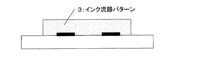
次いで、図3に示すように、上記インク吐出圧力発生素子2を含む基板1上に、溶解可能な樹脂にてインク流路パターン3を形成する。最も一般的な手段としては感光性材料にて形成する手段が挙げられる。該感光性材料は、形成したパターンが容易に溶解除去できる必要がある。本発明で用いられる、ポジ型の感光性樹脂組成物は、塗布後の加熱によって、架橋剤を介したポリアクリレート樹脂の分子間架橋反応が進行し、その後の工程に対する耐溶剤性が向上する一方で、架橋した樹脂膜はマスクを介した露光によるポジ反応によりパターニングが可能である。この時、該感光性樹脂組成物は架橋剤を介した分子間架橋を行っているために、分子同士を直接架橋させた場合に比べて、靭性が極めて大きく、現像時のソルベントショックによるクラックを抑制することができる。さらに、パターニング後の未露光部の樹脂層は、後の工程で電離放射線の照射を行うことで分子崩壊し、低分子の化合物になり溶解除去が可能となる。そのため本発明に於いては、インク流路となる箇所に、本発明によるポジ型の感光性樹脂組成物を用いることで、インク流路パターン形成後に電離放射線照射工程を経て、前記インク流路パターンを分解し、最後の工程での洗い出しを極めて容易に短時間で行うことが出来る。さらに、インク流路パターンが形成される時にはインク流路パターン部分の樹脂が熱架橋反応により不溶化されているため、溶解力の強い溶媒を用いてインク流路壁を形成する被覆樹脂層を形成してもインク流路の形崩れを起こすおそれがない。従って、インク流路パターンの厚みの均一化を容易に達成することができる。また、この熱架橋の工程は低温短時間で架橋可能なため、生産性の向上にもつながる。 Next, as shown in FIG. 3, the ink flow path pattern 3 is formed on the substrate 1 including the ink discharge pressure generating element 2 with a soluble resin. The most common means is a means formed of a photosensitive material. The photosensitive material must be capable of easily dissolving and removing the formed pattern. While the positive photosensitive resin composition used in the present invention undergoes an intermolecular crosslinking reaction of the polyacrylate resin via a crosslinking agent by heating after coating, the solvent resistance to subsequent steps is improved. The crosslinked resin film can be patterned by a positive reaction by exposure through a mask. At this time, since the photosensitive resin composition performs intermolecular cross-linking via a cross-linking agent, it has extremely high toughness compared to the case where the molecules are directly cross-linked with each other, and cracks due to solvent shock during development are present. Can be suppressed. Furthermore, the resin layer in the unexposed area after patterning undergoes molecular collapse by irradiation with ionizing radiation in a later step, and becomes a low molecular compound, which can be dissolved and removed. For this reason, in the present invention, the positive photosensitive resin composition according to the present invention is used in a portion that becomes an ink flow path, and after the ink flow path pattern is formed, the ink flow path pattern is subjected to an ionizing radiation irradiation step. And the washing in the last step can be performed very easily in a short time. Furthermore, since the resin in the ink flow path pattern portion is insolubilized by the thermal crosslinking reaction when the ink flow path pattern is formed, a covering resin layer that forms the ink flow path wall is formed using a solvent having a strong dissolving power. However, there is no possibility that the ink flow path will be deformed. Accordingly, it is possible to easily achieve the uniform thickness of the ink flow path pattern. In addition, this thermal cross-linking step can be cross-linked at a low temperature in a short time, leading to an improvement in productivity.
尚、本発明においてインク流路パターンに用いるポジ型の感光性樹脂組成物は、ノズル構成部材を塗布する際に少なくともノズルに直結している上層にパターニングされていれば、例えば微小液滴が吐出可能な3次元流路を構成するためにインク流路パターンが2層で構成されていても問題ない。これは、インク流路の型崩れが問題となるのは主にノズルの付け根にあたる部分であり、この部分の型崩れを抑えることが出きれば、安定した吐出を得ることができるためである。ただし、この場合、下層のインク流路パターンを形成する樹脂としては、パターン形成後に電離放射線の照射によってポジ型の分子崩壊反応を生じるポジ型レジストを用い、後の工程で上層と同時に溶解除去することが望ましい。この場合、下層のインク流路パターンの形成用レジストは、上層のレジストとは異なる波長の光に対して感度を有するレジストが用いられ、特にポリメチルイソプロペニルケトン(PMIPK)が好適に用いられる。 In the present invention, the positive photosensitive resin composition used for the ink flow path pattern is ejected with, for example, fine liquid droplets as long as it is patterned on at least the upper layer directly connected to the nozzle when the nozzle constituent member is applied. There is no problem even if the ink flow path pattern is composed of two layers in order to form a possible three-dimensional flow path. This is because the deformation of the ink flow path becomes a problem mainly in the portion corresponding to the base of the nozzle, and if it is possible to suppress the deformation of this portion, stable ejection can be obtained. However, in this case, as the resin for forming the ink flow path pattern in the lower layer, a positive resist that generates a positive molecular decay reaction by irradiation with ionizing radiation after pattern formation is used and dissolved and removed simultaneously with the upper layer in a later step. It is desirable. In this case, as the resist for forming the lower layer ink flow path pattern, a resist having sensitivity to light having a wavelength different from that of the upper layer resist is used, and polymethyl isopropenyl ketone (PMIPK) is particularly preferably used.
以上の特性を満足するポジ型の感光性樹脂組成物としては、一般式(1)で示される構造単位を有するポリアクリレート樹脂と、一般式(2)で示されるメラミン化合物およびその縮合物の少なくとも1種を含む感光性樹脂組成物が挙げられる。また、該感光性樹脂組成物は、更に芳香族スルフォニウム塩および芳香族ヨードニウム塩およびトリアジン化合物から選択される少なくとも1種の光酸発生剤を含有しても良い。 The positive photosensitive resin composition satisfying the above characteristics includes at least a polyacrylate resin having a structural unit represented by the general formula (1), a melamine compound represented by the general formula (2), and a condensate thereof. The photosensitive resin composition containing 1 type is mentioned. The photosensitive resin composition may further contain at least one photoacid generator selected from aromatic sulfonium salts, aromatic iodonium salts, and triazine compounds.
(式中、Xは水酸基、炭素数2〜4のアルキロールオキシ基またはメチロールアミノ基を示す。R1及びR2はそれぞれ独立して水素原子、または炭素数1〜3のアルキル基を示す。R3は炭素数1〜3のアルキル基、炭素数1〜3のアルコキシル基、アリール基またはアルキル基の炭素数が1〜2のアラルキル基を示す。nは正の整数、mは0または正の整数である。)
(Wherein, X represents a hydroxyl group, respectively .R 1 and R 2 indicates an alkylol group or methylol amino group having 2 to 4 carbon atoms independently a hydrogen atom, or an alkyl group having 1 to 3 carbon atoms. R 3 represents an alkyl group having 1 to 3 carbon atoms, an alkoxyl group having 1 to 3 carbon atoms, an aryl group, or an aralkyl group having 1 to 2 carbon atoms in an alkyl group, n is a positive integer, m is 0 or positive Is an integer.)
(式中、R1〜R6は水素原子、またはメチロール基または炭素数1〜4のアルコキシ基が結合したアルコキシメチル基を示し、互いに同一でも異なっていても良い。ただし、R1〜R6のうち少なくとも2つはメチロール基または炭素数1〜4のアルコキシ基が結合したアルコキシメチル基を示す。)
このように、流路パターン3を形成した基板1上に、図4に示すように、ノズル構成部材4を通常のスピンコート法、ロールコート法、スリットコート法等の方法で形成する。
ノズル構成部材4としては、後述するインク吐出口6をフォトリソグラフィーで容易にかつ精度よく形成できることから、感光性のものが好ましい。このような感光性ノズル構成部材には、構造材料としての高い機械的強度、下地との密着性、耐インク性と、同時にインク吐出口の微細なパターンをパターニングするための解像性が要求される。これらの特性を満足する材料としては、カチオン重合型のエポキシ樹脂組成物を好適に用いることができる。
(Wherein R1 to R6 represent a hydrogen atom, a methylol group, or an alkoxymethyl group to which an alkoxy group having 1 to 4 carbon atoms is bonded, and may be the same or different from each other, provided that at least 2 of R1 to R6 One represents an methyl group or an alkoxymethyl group to which an alkoxy group having 1 to 4 carbon atoms is bonded.)
Thus, as shown in FIG. 4, the nozzle constituent member 4 is formed on the substrate 1 on which the flow path pattern 3 is formed by a method such as a normal spin coating method, a roll coating method, or a slit coating method.
As the nozzle constituent member 4, a photosensitive member is preferable because an ink discharge port 6 described later can be easily and accurately formed by photolithography. Such photosensitive nozzle constituent members are required to have high mechanical strength as a structural material, adhesion to the base, ink resistance, and resolution for patterning a fine pattern of ink discharge ports at the same time. The As a material satisfying these characteristics, a cationic polymerization type epoxy resin composition can be suitably used.
本発明に用いられるエポキシ樹脂としては、例えばビスフェノールAとエピクロルヒドリンとの反応物のうち分子量がおよそ900以上のもの、含ブロモビスフェノールAとエピクロルヒドリンとの反応物、フェノールノボラックあるいはo−クレゾールノボラックとエピクロルヒドリンとの反応物、特開昭60−161973号明細書、特開昭63−221121号明細書、特開昭64−9216号明細書、特開平2−140219号明細書に記載のオキシシクロヘキサン骨格を有する多官能エポキシ樹脂等があげられるが、これら化合物に限定されるものではない。 Examples of the epoxy resin used in the present invention include a reaction product of bisphenol A and epichlorohydrin having a molecular weight of about 900 or more, a reaction product of bromobisphenol A and epichlorohydrin, a phenol novolak or o-cresol novolak and epichlorohydrin, and the like. The reaction product has an oxycyclohexane skeleton as described in JP-A-60-161973, JP-A-63-221121, JP-A-64-9216, and JP-A-2-140219. Examples thereof include polyfunctional epoxy resins, but are not limited to these compounds.
また、上述のエポキシ化合物においては、好ましくはエポキシ当量が2000以下、さらに好ましくはエポキシ当量が1000以下の化合物が好適に用いられる。これは、エポキシ当量が2000を越えると、硬化反応の際に架橋密度が低下し、密着性、耐インク性に問題が生じる場合があるからである。 In the above-described epoxy compound, a compound having an epoxy equivalent of 2000 or less, more preferably 1000 or less, is preferably used. This is because if the epoxy equivalent exceeds 2000, the crosslinking density is lowered during the curing reaction, which may cause problems in adhesion and ink resistance.
また、カチオン重合型の樹脂組成物であるため、後述するインク吐出口6をフォトリソグラフィーによって、高い機械的強度、下地との密着性、耐インク性と、同時にインク吐出口の微細なパターンをパターニングするための解像性をも満足しながら容易にかつ精度よく形成できる。 Further, since it is a cationic polymerization type resin composition, the ink discharge port 6 described later is patterned by photolithography, with high mechanical strength, adhesion to the substrate, and ink resistance, and at the same time, a fine pattern of the ink discharge port. Therefore, it can be formed easily and accurately while satisfying the resolution for achieving the above.
上記樹脂を硬化させるための光カチオン重合開始剤としては、芳香族ヨードニウム塩、芳香族スルホニウム塩[J.POLYMER SCI:Symposium No. 56 383−395(1976)参照]や旭電化工業株式会社より上市されているSP−150、SP−170等が挙げられる。 Examples of the photocationic polymerization initiator for curing the resin include aromatic iodonium salts, aromatic sulfonium salts [J. POLYMER SCI: See Symposium No. 56 383-395 (1976)] and SP-150, SP-170 and the like marketed by Asahi Denka Kogyo Co., Ltd.
また、上述の光カチオン重合開始剤は、還元剤を併用し加熱することによって、カチオン重合を促進(単独の光カチオン重合に比較して架橋密度が向上する。)させることができる。ただし、光カチオン重合開始剤と還元剤を併用する場合、常温では反応せず一定温度以上(好ましくは60℃以上)で反応するいわゆるレドックス型の開始剤系になるように、還元剤を選択する必要がある。このような還元剤としては、銅化合物、特に反応性とエポキシ樹脂への溶解性を考慮して銅トリフラート(トリフルオロメタンスルフォン酸銅(II))が最適である。さらに上記組成物に対して必要に応じて添加剤など適宜添加することが可能である。例えば、樹脂の弾性率を下げる目的で可撓性付与剤を添加したり、あるいは下地基板との更なる密着力を得るためにシランカップリング剤を添加することなどが挙げられる。 Moreover, the above-mentioned photocationic polymerization initiator can accelerate | stimulate cationic polymerization (a crosslinking density improves compared with single photocationic polymerization) by using a reducing agent together and heating. However, when a photocationic polymerization initiator and a reducing agent are used in combination, the reducing agent is selected so that it becomes a so-called redox type initiator system that does not react at room temperature and reacts at a certain temperature or higher (preferably 60 ° C. or higher). There is a need. As such a reducing agent, a copper compound, particularly copper triflate (copper trifluoromethanesulfonate (II)) is most suitable in consideration of reactivity and solubility in an epoxy resin. Furthermore, additives and the like can be appropriately added to the composition as necessary. For example, a flexibility imparting agent may be added for the purpose of lowering the elastic modulus of the resin, or a silane coupling agent may be added to obtain a further adhesion to the base substrate.
次いで、ノズル構成部材4上に、感光性を有する撥インク剤層5を形成する(図5)。撥インク剤層5は、スピンコート法、ロールコート法、スリットコート法等の塗布方法により形成可能であるが、未硬化のノズル形成部材4上に形成されるため、両者が必要以上に相溶しないことが必要である。また、上述したように、ノズル構成部材4としてカチオン重合性組成物が用いられる場合には、感光性を有する撥インク剤層5にもカチオン重合可能な官能基を含有させておくことが好ましい。 ノズル構成部材4には、光重合開始剤を必須成分として含むが、撥インク剤層5には必ずしも光重合開始剤を含む必要はなく、ノズル材料硬化時に発生する重合開始剤で反応、硬化させても良い。 Next, an ink repellent agent layer 5 having photosensitivity is formed on the nozzle component 4 (FIG. 5). The ink repellent agent layer 5 can be formed by a coating method such as a spin coating method, a roll coating method, or a slit coating method. However, since the ink repellent agent layer 5 is formed on the uncured nozzle forming member 4, both are more compatible than necessary. It is necessary not to. As described above, when a cationically polymerizable composition is used as the nozzle constituent member 4, it is preferable that the photosensitive ink repellent agent layer 5 also contains a cationically polymerizable functional group. The nozzle component 4 includes a photopolymerization initiator as an essential component, but the ink repellent agent layer 5 does not necessarily include a photopolymerization initiator, and is reacted and cured with a polymerization initiator generated when the nozzle material is cured. May be.
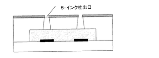
次いで、マスク(不図示)を介してパターン露光を行い、現像処理を施してインク吐出口6を形成する(図6)。パターン露光されたノズル構成部材4および撥インク剤層5を、適当な溶剤を用いて現像することにより、図6に示すように、インク吐出口6を形成することができる。 Next, pattern exposure is performed through a mask (not shown), and development processing is performed to form ink discharge ports 6 (FIG. 6). By developing the pattern-exposed nozzle component 4 and the ink repellent agent layer 5 using an appropriate solvent, an ink discharge port 6 can be formed as shown in FIG.
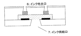
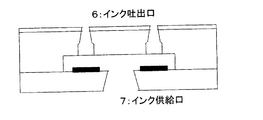
次いで、インク供給口7を形成する(図7)。インク供給口7の形成方法としては、エキシマレーザーを用いる方法、ドリルあるいはサンドブラストによる方法、エッチングによる方法等を適宜使用することができる。 Next, the ink supply port 7 is formed (FIG. 7). As a method for forming the ink supply port 7, a method using an excimer laser, a method using a drill or sandblast, a method using etching, or the like can be used as appropriate.
次いで切断分離工程を経た後(不図示)、被処理基板に電離放射線を照射することにより、インク流路パターン3を可溶化し、インク流路パターン3を溶解除去する。必要に応じて加熱処理を施すことにより、ノズル構成部材4および撥インク剤層5を完全に硬化させる。さらに、インク供給のための部材(不図示)の接合、インク吐出圧力発生素子を駆動するための電気的接合(不図示)を行って、インクジェットヘッドを完成させる(図8)。 Next, after a cutting and separating step (not shown), the substrate is irradiated with ionizing radiation, so that the ink flow path pattern 3 is solubilized and the ink flow path pattern 3 is dissolved and removed. The nozzle constituent member 4 and the ink repellent agent layer 5 are completely cured by performing a heat treatment as necessary. Further, a member (not shown) for supplying ink and an electric connection (not shown) for driving the ink discharge pressure generating element are performed to complete the ink jet head (FIG. 8).
以下に実施例を示し、本発明を更に詳細に説明する。なお、以下の実施例2、4、6及び8が本発明の範囲に含まれる実施例であり、その他の実施例は、本発明に関連する参考例である。 The following examples illustrate the present invention in more detail. The following Examples 2, 4, 6, and 8 are examples included in the scope of the present invention, and the other examples are reference examples related to the present invention.
実施例1
インクジェットヘッドの作成
本実施例では、前述の図1〜図8に示す手順にしたがって、インクジェットヘッドを作製し評価を行った。まず、インク吐出圧力発生素子2としての電気熱変換素子(材質HfB2 からなるヒーター)と、インク流路およびノズル形勢部位にSiN+Taの積層膜(不図示)を有するであるシリコン基板1を準備した(図2)。次いで、被処理基板上に、ポジ型の感光性樹脂組成物層を形成し、流路パターン3を形成した(図3)。感光性樹脂組成物としては、以下のメタクリル酸とメタクリル酸メチルの共重合体(メタクリル酸:メタクリル酸メチル=20:80(質量比)・化合物8)に架橋剤としてヘキサメトキシメチルメラミン(三和ケミカル製ニカラック MW−100L)をメタクリル酸に対して3mol%加えた樹脂を用いた。
Example 1
Preparation of Inkjet Head In this example, an inkjet head was prepared and evaluated according to the procedure shown in FIGS. First, an electrothermal conversion element (a heater made of material HfB2) as an ink discharge pressure generating element 2 and a silicon substrate 1 having a laminated film (not shown) of SiN + Ta in an ink flow path and a nozzle shape portion were prepared ( Figure 2). Next, a positive type photosensitive resin composition layer was formed on the substrate to be processed, and a flow path pattern 3 was formed (FIG. 3). As the photosensitive resin composition, the following copolymer of methacrylic acid and methyl methacrylate (methacrylic acid: methyl methacrylate = 20: 80 (mass ratio) · compound 8) and hexamethoxymethylmelamine (Sanwa) as a crosslinking agent were used. A resin obtained by adding 3 mol% of Nicalac MW-100L (chemical) to methacrylic acid was used.
重量平均分子量(Mw:ポリスチレン換算)=100000
分散度(Mw/Mn)=2.5
この樹脂粉末をシクロヘキサノンに約30wt%の固形分濃度にて溶解し、レジスト液として使用した。該レジスト液を、スピンコート法にて塗布し、100℃で3分プリベークした後、150℃のオーブンで30分焼成した。この硬化により、架橋剤による熱架橋反応が進行した。尚、熱処理後のレジスト層の膜厚は15μmであった。その後、200〜280nmの波長のUV光を用いて、50000mJ/m2の露光量にて露光し、以下の組成の現像液にて現像し、イソプロピルアルコールにてリンス処理を行うことでインク流路パターン3を得た。
<現像液>
ジエチレングリコールモノブチルエーテル:60vol%
エタノールアミン:5vol%
モルホリン:20vol%
イオン交換水:15vol%
次いで、被処理基板上に以下の組成からなる感光性樹脂組成物を用いてスピンコートを行い(平板上膜厚20μm)、100℃で2分間(ホットプレート)のベークを行い、ノズル構成部材4を形成した(図4)。
エポキシ樹脂:EHPE(ダイセル化学工業製):100重量部
添加剤:1、4HFAB(セントラル硝子製):20重量部
光カチオン重合開始剤:SP−170(旭電化工業製):2重量部
シランカップリング剤:A−187(日本ユニカー製):5重量部
メチルイソブチルケトン:100重量部
ジグライム:100重量部
引き続き、被処理基板上に以下の組成からなる感光性樹脂組成物を用いて、スピンコートにより1μmの膜厚となるように塗布し、80℃で3分間(ホットプレート)のベークを行い、撥インク剤層5を形成した(図5)。
EHPE―3158(ダイセル化学工業製):35重量部
2、2―ビス(4―グリシジルオキシフェニル)ヘキサフロロプロパン:25重量部
1、4―ビス(2―ヒドロキシヘキサフロロイソプロピル)ベンゼン:25重量部
3―(2―パーフルオロヘキシル)エトキシー1、2―エポキシプロパン:16重量部
A−187(日本ユニカー製):4重量部
SP―170(旭電化工業製):2重量部
ジエチレングリコールモノエチルエーテル:100重量部
次いで、ノズル構成部材4および撥インク剤層5のパターニングを行い、インク吐出口6を形成した(図6)。なお、本実施例ではφ15μmの吐出口パターンを形成した。
Weight average molecular weight (Mw: polystyrene conversion) = 100000
Dispersity (Mw / Mn) = 2.5
This resin powder was dissolved in cyclohexanone at a solid concentration of about 30 wt% and used as a resist solution. The resist solution was applied by spin coating, prebaked at 100 ° C. for 3 minutes, and then baked in an oven at 150 ° C. for 30 minutes. By this curing, the thermal crosslinking reaction with the crosslinking agent proceeded. The film thickness of the resist layer after the heat treatment was 15 μm. Then, using UV light having a wavelength of 200 to 280 nm, exposure is performed at an exposure amount of 50000 mJ / m 2, development is performed with a developer having the following composition, and rinse treatment is performed with isopropyl alcohol to thereby form an ink flow path pattern. 3 was obtained.
<Developer>
Diethylene glycol monobutyl ether: 60vol%
Ethanolamine: 5vol%
Morpholine: 20vol%
Ion exchange water: 15vol%
Next, spin coating is performed on the substrate to be processed using the photosensitive resin composition having the following composition (film thickness on the flat plate: 20 μm), baking is performed at 100 ° C. for 2 minutes (hot plate), and the nozzle component 4 Was formed (FIG. 4).
Epoxy resin: EHPE (manufactured by Daicel Chemical Industries): 100 parts by weight Additive: 1, 4HFAB (manufactured by Central Glass): 20 parts by weight Photocationic polymerization initiator: SP-170 (manufactured by Asahi Denka Kogyo): 2 parts by weight silane cup Ring agent: A-187 (manufactured by Nihon Unicar): 5 parts by weight Methyl isobutyl ketone: 100 parts by weight Diglyme: 100 parts by weight Subsequently, a photosensitive resin composition having the following composition on the substrate to be processed was spin-coated. Was applied to a thickness of 1 μm and baked at 80 ° C. for 3 minutes (hot plate) to form an ink repellent agent layer 5 (FIG. 5).
EHPE-3158 (manufactured by Daicel Chemical Industries): 35 parts by weight 2,2-bis (4-glycidyloxyphenyl) hexafluoropropane: 25 parts by weight 1,4-bis (2-hydroxyhexafluoroisopropyl) benzene: 25 parts by weight 3- (2-perfluorohexyl) ethoxy-1,2-epoxypropane: 16 parts by weight A-187 (Nihon Unicar): 4 parts by weight SP-170 (Asahi Denka Kogyo): 2 parts by weight diethylene glycol monoethyl ether: 100 parts by weight Next, the nozzle constituent member 4 and the ink repellent agent layer 5 were patterned to form an ink discharge port 6 (FIG. 6). In the present example, a discharge port pattern of φ15 μm was formed.
次に、被処理基板の裏面にポリエーテルアミド樹脂組成物(日立化成製HIMAL)を用いてエッチングマスクを形成し、例えば特開平5−124199号明細書に開示されている既知の手法により、シリコン基板の異方性エッチングを行って、インク供給口7を形成した(図7)。なお、この際エッチング液から撥インク剤層5を保護する目的で、保護膜(東京応化工業製OBC)を撥インク剤層5上に塗布した。
次いで、保護膜として用いたOBCをキシレンを用いて溶解除去した後、200〜280nmの波長の光を用いて、ノズル構成部材および撥インク剤層越しに50000mJ/cm2の露光量で全面露光を行い、流路パターン3を可溶化した。引き続き、乳酸メチル中に超音波を付与しつつ浸漬し、流路パターン3を溶解除去することによりインクジェットヘッドを作成した(図8)。
Next, an etching mask is formed on the back surface of the substrate to be processed by using a polyether amide resin composition (HIMAL manufactured by Hitachi Chemical Co., Ltd.). For example, silicon is formed by a known method disclosed in Japanese Patent Laid-Open No. 5-124199. The substrate was anisotropically etched to form an ink supply port 7 (FIG. 7). At this time, a protective film (OBC manufactured by Tokyo Ohka Kogyo Co., Ltd.) was applied on the ink repellent agent layer 5 for the purpose of protecting the ink repellent agent layer 5 from the etching solution.
Next, the OBC used as the protective film is dissolved and removed using xylene, and then the entire surface is exposed through the nozzle constituent member and the ink repellent layer with an exposure amount of 50000 mJ / cm 2 using light having a wavelength of 200 to 280 nm. The flow path pattern 3 was solubilized. Subsequently, the ink jet head was created by immersing in methyl lactate while applying ultrasonic waves, and dissolving and removing the flow path pattern 3 (FIG. 8).
このようにして、作成したインクジェットヘッドの品質を確認するため、まず顕微鏡にてインク流路形状を観察した。尚、本実施例に用いられるインク流路パターンは全て無色透明であるため、インク流路の形状はインク流路パターンを通して観察することができる。その結果、インク流路の形状が崩れているものは見受けられなかった。さらに、記録装置に装着し、純水/グリセリン/ダイレクトブラック154(水溶性黒色染料)=65/30/5からなるインクを用いて印字を行ったところ、安定な印字が可能であった。 Thus, in order to confirm the quality of the produced inkjet head, the ink flow path shape was first observed with the microscope. Since all ink flow path patterns used in this embodiment are colorless and transparent, the shape of the ink flow path can be observed through the ink flow path pattern. As a result, no ink channel shape was broken. Furthermore, when mounted on a recording apparatus and printing was performed using an ink comprising pure water / glycerin / direct black 154 (water-soluble black dye) = 65/30/5, stable printing was possible.
実施例2
図9〜17に示す工程に従ってインクジェットヘッドを作製した。実施例1と同様にしてインク吐出圧力発生素2を含む基板上(図9)に第一のポジ型レジスト層8を形成した(図9)。尚、第一のポジ型レジストとしては、ポリメチルイソプロペニルケトン(東京応化製ODUR)を用いた。第一のポジ型レジスト液を、スピンコート法にて塗布し、120℃で3分間のベークを行った。尚、熱処理後のレジスト層の膜厚は10μmであった。次いで、第二のポジ型レジスト層9を形成した(図10)。尚、第二のポジ型レジストとしては、以下のメタクリル酸とメタクリル酸メチルの共重合体(メタクリル酸:メタクリル酸メチル=20:80・化合物8)に架橋剤として
ヘキサメトキシメチルメラミン(三和ケミカル製 ニカラック MW-100L)
をメタクリル酸に対して3mol%加えた樹脂を用いた。
Example 2
An ink jet head was produced according to the steps shown in FIGS. In the same manner as in Example 1, the first positive resist layer 8 was formed on the substrate (FIG. 9) including the ink discharge pressure generating element 2 (FIG. 9). As the first positive resist, polymethyl isopropenyl ketone (ODUR manufactured by Tokyo Ohka Kogyo Co., Ltd.) was used. The first positive resist solution was applied by spin coating and baked at 120 ° C. for 3 minutes. The film thickness of the resist layer after the heat treatment was 10 μm. Next, a second positive resist layer 9 was formed (FIG. 10). As the second positive resist, the following copolymer of methacrylic acid and methyl methacrylate (methacrylic acid: methyl methacrylate = 20: 80 · compound 8) and hexamethoxymethylmelamine (Sanwa Chemical) as a crosslinking agent are used. Nicarak MW-100L manufactured)
A resin with 3 mol% added to methacrylic acid was used.
重量平均分子量(Mw:ポリスチレン換算)=100000
分散度(Mw/Mn)=2.5
この樹脂をシクロヘキサノンに30wt%の固形分濃度にて溶解し、レジスト液として使用した。該レジスト液をスピンコート法にて塗布し、120℃で3分プリベークした後、窒素雰囲気中オーブンにて140℃30分間の熱処理を行った。尚、熱処理後のレジスト層の膜厚は10μmであった。
Weight average molecular weight (Mw: polystyrene conversion) = 100000
Dispersity (Mw / Mn) = 2.5
This resin was dissolved in cyclohexanone at a solid concentration of 30 wt% and used as a resist solution. The resist solution was applied by spin coating, pre-baked at 120 ° C. for 3 minutes, and then heat-treated at 140 ° C. for 30 minutes in an oven in a nitrogen atmosphere. The film thickness of the resist layer after the heat treatment was 10 μm.
引き続き、第二のポジ型レジスト層のパターニングを行った。露光装置としてウシオ電機製Deep-UV露光装置UX-3000を用い、270nm以上の波長を遮断する光学フィルターを装着して、20000mJ/cm2の露光量にてパターン露光し、以下の組成の現像液にて現像した後、イソプロピルアルコールにてリンス処理を行って、第二の流路パターン10を形成した(図11)。 Subsequently, the second positive resist layer was patterned. Using a Ushio-made Deep-UV exposure device UX-3000 as an exposure device, mounting an optical filter that blocks wavelengths of 270 nm or more, pattern exposure at an exposure amount of 20000 mJ / cm 2, to a developer having the following composition After the development, a rinsing process was performed with isopropyl alcohol to form the second flow path pattern 10 (FIG. 11).
<現像液>
ジエチレングリコールモノブチルエーテル:60vol%
エタノールアミン:5vol%
モルホリン:20vol%
イオン交換水:15vol%
次いで、第一のポジ型レジスト層のパターニングを行った。上記と同一の露光装置を用い、260nm以下の波長の光を遮断する光学フィルターを装着して、5000mJ/cm2の露光量にてパターン露光し、メチルイソブチルケトンにて現像、イソプロピルアルコールにてリンス処理を行って、第一の流路パターン11を形成した(図12)。
次いで、被処理基板上に、実施例1と同様な方法でノズル構成部材4(図13)、撥インク剤層5(図14)を形成し、パターン露光することでインク吐出口6を形成した(図15)。尚、本実施例ではφ10μmの吐出口パターンを形成した。
<Developer>
Diethylene glycol monobutyl ether: 60vol%
Ethanolamine: 5vol%
Morpholine: 20vol%
Ion exchange water: 15vol%
Next, the first positive resist layer was patterned. Using the same exposure apparatus as above, wearing an optical filter that blocks light with a wavelength of 260 nm or less, pattern exposure at an exposure amount of 5000 mJ / cm2, developing with methyl isobutyl ketone, and rinsing with isopropyl alcohol And the first flow path pattern 11 was formed (FIG. 12).
Next, the nozzle constituent member 4 (FIG. 13) and the ink repellent agent layer 5 (FIG. 14) were formed on the substrate to be processed in the same manner as in Example 1, and the ink discharge ports 6 were formed by pattern exposure. (FIG. 15). In this example, a discharge port pattern of φ10 μm was formed.
次に、実施例1と同様の方法で異方性エッチングによって、インク供給口7を形成した(図16)。次いで、上記と同一の露光装置を用い、光学フィルターを装着せずに、ノズル構成部材および撥インク剤層越しに20000mJ/cm2の露光量で全面露光を行い、流路パターン10及び11を可溶化した。引き続き、乳酸メチル中に超音波を付与しつつ浸漬し、流路パターン10及び11を溶解除去することによりインクジェットヘッドを作成した(図17)。 Next, an ink supply port 7 was formed by anisotropic etching in the same manner as in Example 1 (FIG. 16). Next, using the same exposure apparatus as described above, without exposing the optical filter, the entire surface exposure is performed through the nozzle constituent member and the ink repellent agent layer at an exposure amount of 20000 mJ / cm 2 to solubilize the flow path patterns 10 and 11. did. Subsequently, the ink jet head was created by immersing it in methyl lactate while applying ultrasonic waves, and dissolving and removing the flow path patterns 10 and 11 (FIG. 17).
実施例1と同様に、顕微鏡にてインク流路形状を観察した。その結果、インク流路の形状が崩れているものは見受けられなかった。さらに、実施例1と同様に印字を行ったこところ、安定な印字が可能であった。 In the same manner as in Example 1, the ink flow path shape was observed with a microscope. As a result, no ink channel shape was broken. Further, when printing was performed in the same manner as in Example 1, stable printing was possible.
実施例3
実施例1と同様にして電気熱変換素子を形成した基板に対して、感光性樹脂組成物として、2−ヒドロキシエチルメタクリレートとメタクリル酸メチルの共重合体(2−ヒドロキシエチルメタクリレート:メタクリル酸メチル=20:80・化合物9)に架橋剤としてペンタメトキシメチルメラミン(三和ケミカル製 ニカラック MX−750LM)を2−ヒドロキシエチルメタクリレートに対して3mol%加えた樹脂を用いた。
Example 3
As the photosensitive resin composition, a copolymer of 2-hydroxyethyl methacrylate and methyl methacrylate (2-hydroxyethyl methacrylate: methyl methacrylate = A resin obtained by adding 3 mol% of pentamethoxymethylmelamine (Nikalac MX-750LM, manufactured by Sanwa Chemical Co., Ltd.) to 20: 80 · compound 9) as a crosslinking agent with respect to 2-hydroxyethyl methacrylate was used.
重量平均分子量(Mw:ポリスチレン換算)=80000
分散度(Mw/Mn)=2.2
実施例1と同一の条件にてインク流路パターン層を塗布、パターニングし、最後にインク流路パターンを形成する樹脂を溶出し、インクジェットヘッドを作成した。実施例1と同様に、顕微鏡にてインク流路形状を観察した。その結果、インク流路の形状が崩れているものは見受けられなかった。さらに、実施例1と同様に印字を行ったこところ、安定な印字が可能であった。
Weight average molecular weight (Mw: polystyrene conversion) = 80000
Dispersity (Mw / Mn) = 2.2
The ink flow path pattern layer was applied and patterned under the same conditions as in Example 1, and finally the resin forming the ink flow path pattern was eluted to produce an ink jet head. In the same manner as in Example 1, the ink flow path shape was observed with a microscope. As a result, no ink channel shape was broken. Further, when printing was performed in the same manner as in Example 1, stable printing was possible.
実施例4
実施例2と同様にして電気熱変換素子を形成した基板に対して、第二のポジ型レジストとして、2−ヒドロキシエチルメタクリレートとメタクリル酸メチルの共重合体(2−ヒドロキシエチルメタクリレート:メタクリル酸メチル=20:80・化合物9)に架橋剤としてペンタメトキシメチルメラミン(三和ケミカル製 ニカラック MX−750LM)を2−ヒドロキシエチルメタクリレートに対して3mol%加えた樹脂を用いた。
Example 4
As a second positive resist, a copolymer of 2-hydroxyethyl methacrylate and methyl methacrylate (2-hydroxyethyl methacrylate: methyl methacrylate) was applied to the substrate on which the electrothermal conversion element was formed in the same manner as in Example 2. = 20: 80 · Compound 9) A resin obtained by adding 3 mol% of pentamethoxymethyl melamine (Nikalac MX-750LM, manufactured by Sanwa Chemical Co., Ltd.) as a crosslinking agent to 2-hydroxyethyl methacrylate was used.
重量平均分子量(Mw:ポリスチレン換算)=80000
分散度(Mw/Mn)=2.2
実施例2と同一の条件にて第1及び第2流路パターン層をそれぞれ塗布、パターニングし、最後にこれらの流路パターンを形成する樹脂を溶出し、インクジェットヘッドを作成した。実施例1と同様に、顕微鏡にてインク流路形状を観察した。その結果、インク流路の形状が崩れているものは見受けられなかった。さらに、実施例1と同様に印字を行ったこところ、安定な印字が可能であった。
Weight average molecular weight (Mw: polystyrene conversion) = 80000
Dispersity (Mw / Mn) = 2.2
The first and second flow path pattern layers were respectively applied and patterned under the same conditions as in Example 2, and finally the resin forming these flow path patterns was eluted to prepare an ink jet head. In the same manner as in Example 1, the ink flow path shape was observed with a microscope. As a result, no ink channel shape was broken. Further, when printing was performed in the same manner as in Example 1, stable printing was possible.
実施例5
ポジ型の感光性樹脂組成物に、光酸発生剤としてSP-172(旭電化工業製)を樹脂に対して2重量部加え、パターニングの際の露光量を半分とし、PEBとしてホットプレートで100℃−180秒の処理を行った以外は実施例1と同様にしてインクジェットヘッドを製造した。
Example 5
SP-172 (manufactured by Asahi Denka Kogyo Co., Ltd.) as a photoacid generator is added to the positive photosensitive resin composition in an amount of 2 parts by weight based on the resin, the exposure during patterning is halved, and PEB is 100 on a hot plate. An ink jet head was manufactured in the same manner as in Example 1 except that the treatment was performed at ° C for 180 seconds.
実施例1と同様に、顕微鏡にてインク流路形状を観察した。その結果、インク流路の形状が崩れているものは見受けられなかった。さらに、実施例1と同様に印字を行ったこところ、安定な印字が可能であった。 In the same manner as in Example 1, the ink flow path shape was observed with a microscope. As a result, no ink channel shape was broken. Further, when printing was performed in the same manner as in Example 1, stable printing was possible.
実施例6
第二のポジ型レジストに、光酸発生剤としてSP-172(旭電化工業製)を樹脂に対して2重量部加え、パターニングの際の露光量を半分とし、PEBとしてホットプレートで100℃−180秒の処理を行った以外は実施例2と同様にしてインクジェットヘッドを製造した。実施例1と同様に、顕微鏡にてインク流路形状を観察した。その結果、インク流路の形状が崩れているものは見受けられなかった。さらに、実施例1と同様に印字を行ったこところ、安定な印字が可能であった。
Example 6
SP-172 (manufactured by Asahi Denka Kogyo Co., Ltd.) as a photoacid generator is added to the second positive resist in an amount of 2 parts by weight based on the resin, the exposure during patterning is halved, and 100 ° C. on a hot plate as PEB An inkjet head was manufactured in the same manner as in Example 2 except that the treatment for 180 seconds was performed. In the same manner as in Example 1, the ink flow path shape was observed with a microscope. As a result, no ink channel shape was broken. Further, when printing was performed in the same manner as in Example 1, stable printing was possible.
実施例7
ポジ型の感光性樹脂組成物に、光酸発生剤としてSP-172(旭電化工業製)を樹脂に対して2重量部加え、パターニングの際の露光量を半分とし、PEBとしてホットプレートで100℃−180秒の処理を行った以外は実施例3と同様にしてインクジェットヘッドを製造した。実施例1と同様に、顕微鏡にてインク流路形状を観察した。その結果、インク流路の形状が崩れているものは見受けられなかった。さらに、実施例1と同様に印字を行ったこところ、安定な印字が可能であった。
Example 7
SP-172 (manufactured by Asahi Denka Kogyo Co., Ltd.) as a photoacid generator is added to the positive photosensitive resin composition in an amount of 2 parts by weight based on the resin, the exposure during patterning is halved, and PEB is 100 on a hot plate. An ink jet head was manufactured in the same manner as in Example 3 except that the treatment was performed at ° C for 180 seconds. In the same manner as in Example 1, the ink flow path shape was observed with a microscope. As a result, no ink channel shape was broken. Further, when printing was performed in the same manner as in Example 1, stable printing was possible.
実施例8
第二のポジ型レジストに、光酸発生剤としてSP-172(旭電化工業製)を樹脂に対して2重量部加え、パターニングの際の露光量を半分とし、PEBとしてホットプレートで100℃−180秒の処理を行った以外は実施例4と同様にしてインクジェットヘッドを製造した。実施例1と同様に、顕微鏡にてインク流路形状を観察した。その結果、インク流路の形状が崩れているものは見受けられなかった。さらに、実施例1と同様に印字を行ったこところ、安定な印字が可能であった。
Example 8
SP-172 (manufactured by Asahi Denka Kogyo Co., Ltd.) as a photoacid generator is added to the second positive resist in an amount of 2 parts by weight based on the resin, the exposure during patterning is halved, and 100 ° C. on a hot plate as PEB An inkjet head was manufactured in the same manner as in Example 4 except that the treatment for 180 seconds was performed. In the same manner as in Example 1, the ink flow path shape was observed with a microscope. As a result, no ink channel shape was broken. Further, when printing was performed in the same manner as in Example 1, stable printing was possible.
比較例1
実施例1と同様にして電気熱変換素子を形成した基板に対して、感光性樹脂組成物として、メタクリル酸とメタクリル酸メチルの共重合体を用いた。
Comparative Example 1
A copolymer of methacrylic acid and methyl methacrylate was used as the photosensitive resin composition for the substrate on which the electrothermal conversion element was formed in the same manner as in Example 1.
重量平均分子量(Mw:ポリスチレン換算)=100000
分散度(Mw/Mn)=2.5
この樹脂をシクロヘキサノンに30wt%の固形分濃度にて溶解し、レジスト液として使用した。該レジスト液をスピンコート法にて塗布し、120℃で3分プリベークした後、窒素雰囲気中オーブンにて140℃30分間の熱処理を行った。尚、熱処理後のレジスト層の膜厚は15μmであった。その後、200〜280nmの波長のUV光を用いて、500000mJ/m2の露光量にて露光し、以下の組成の現像液にて現像したが、架橋反応が進行せず、未露光部も現像液に対して溶解し、目的のインク流路パターンを形成することが出来なかった。
Weight average molecular weight (Mw: polystyrene conversion) = 100000
Dispersity (Mw / Mn) = 2.5
This resin was dissolved in cyclohexanone at a solid concentration of 30 wt% and used as a resist solution. The resist solution was applied by spin coating, pre-baked at 120 ° C. for 3 minutes, and then heat-treated at 140 ° C. for 30 minutes in an oven in a nitrogen atmosphere. The film thickness of the resist layer after the heat treatment was 15 μm. Then, using UV light having a wavelength of 200 to 280 nm, the exposure was performed with an exposure amount of 500,000 mJ / m 2, and development was performed with a developer having the following composition. The target ink flow path pattern could not be formed.
<現像液>
ジエチレングリコールモノブチルエーテル:60vol%
エタノールアミン:5vol%
モルホリン:20vol%
イオン交換水:15vol%
<Developer>
Diethylene glycol monobutyl ether: 60vol%
Ethanolamine: 5vol%
Morpholine: 20vol%
Ion exchange water: 15vol%
1 基板
2 インク吐出圧力発生素子
3 流路パターン
4 ノズル構成部材
5 撥インク剤層
6 インク吐出口
7 インク供給口
8 第一のポジ型レジスト層
9 第二のポジ型レジスト層
10 第二の流路パターン
11 第一の流路パターン
DESCRIPTION OF SYMBOLS 1 Substrate 2 Ink discharge pressure generating element 3 Flow path pattern 4 Nozzle constituent member 5 Ink repellent agent layer 6 Ink discharge port 7 Ink supply port 8 First positive resist layer 9 Second positive resist layer 10 Second flow Road pattern 11 First flow path pattern
Claims (8)
前記エネルギー発生素子を備える基板を用意する工程と、
前記基板上に、第一のポジ型レジストからなる第一のポジ型レジスト層を形成する工程と、
前記第一のポジ型レジスト層上に、下記一般式(1)で示される構造を有するポリアクリレート樹脂と、下記一般式(2)で示されるメラミン化合物およびその縮合物の少なくとも1種である縮合性の架橋剤とを含む第二のポジ型レジストからなる第二のポジ型レジスト層を形成する工程と、
前記第二のポジ型レジスト層を露光及び現像して、前記インク流路の一部の型となる第二のインク流路パターンを形成する工程と、
前記第一のポジ型レジスト層を露光及び現像して、前記インク流路の残部の型となる第一のインク流路パターンを形成する工程と、
前記第一及び第二のインク流路パターン上に、前記インク流路の壁を形成するための被覆樹脂層を形成する工程と、
前記被覆樹脂層に前記吐出口を形成する工程と、
前記第一及び第二のインク流路パターンを除去して前記インク流路を形成する工程と、
を有することを特徴とするインクジェットヘッドの製造方法。
Preparing a substrate comprising the energy generating element;
Forming a first positive resist layer made of a first positive resist on the substrate;
Condensation which is at least one of a polyacrylate resin having a structure represented by the following general formula (1), a melamine compound represented by the following general formula (2) and a condensate thereof on the first positive resist layer A step of forming a second positive resist layer comprising a second positive resist containing a functional crosslinking agent ;
Exposing and developing the second positive resist layer to form a second ink flow path pattern that becomes a partial mold of the ink flow path;
Exposing and developing the first positive resist layer to form a first ink flow path pattern that becomes a mold of the remaining portion of the ink flow path;
Said first and second ink flow path pattern, and forming a coating resin layer for forming a wall of said ink flow path,
And forming said discharge port to said coating resin layer,
Forming a pre-listening ink flow path by divided the first and second ink flow path pattern,
A method of manufacturing an ink jet head, characterized that you have a.
Priority Applications (7)
| Application Number | Priority Date | Filing Date | Title |
|---|---|---|---|
| JP2004190484A JP4480141B2 (en) | 2004-06-28 | 2004-06-28 | Method for manufacturing ink jet recording head |
| CN200580021432XA CN1977217B (en) | 2004-06-28 | 2005-06-24 | Photosensitive resin composition, ink jet head using photosensitive resin composition, and process for manufacturing ink jet head |
| EP05780110.2A EP1763705B1 (en) | 2004-06-28 | 2005-06-24 | Ink jet head using photosensitive resin composition, and process for manufacturing ink jet head |
| TW094121252A TWI310483B (en) | 2004-06-28 | 2005-06-24 | Photosensitive resin composition, ink jet head using photosensitive resin composition, and process for manufacturing ink jet head |
| PCT/JP2005/012160 WO2006001515A1 (en) | 2004-06-28 | 2005-06-24 | Photosensitive resin composition, ink jet head using photosensitive resin composition, and process for manufacturing ink jet head |
| US10/577,255 US7611827B2 (en) | 2004-06-28 | 2005-06-24 | Photosensitive resin composition, ink jet head using photosensitive resin composition, and process for manufacturing ink jet head |
| KR1020077001946A KR100893414B1 (en) | 2004-06-28 | 2005-06-24 | Photosensitive resin composition, ink jet head using photosensitive resin composition, and process for manufacturing ink jet head |
Applications Claiming Priority (1)
| Application Number | Priority Date | Filing Date | Title |
|---|---|---|---|
| JP2004190484A JP4480141B2 (en) | 2004-06-28 | 2004-06-28 | Method for manufacturing ink jet recording head |
Publications (3)
| Publication Number | Publication Date |
|---|---|
| JP2006011182A JP2006011182A (en) | 2006-01-12 |
| JP2006011182A5 JP2006011182A5 (en) | 2007-08-09 |
| JP4480141B2 true JP4480141B2 (en) | 2010-06-16 |
Family
ID=35033645
Family Applications (1)
| Application Number | Title | Priority Date | Filing Date |
|---|---|---|---|
| JP2004190484A Expired - Fee Related JP4480141B2 (en) | 2004-06-28 | 2004-06-28 | Method for manufacturing ink jet recording head |
Country Status (7)
| Country | Link |
|---|---|
| US (1) | US7611827B2 (en) |
| EP (1) | EP1763705B1 (en) |
| JP (1) | JP4480141B2 (en) |
| KR (1) | KR100893414B1 (en) |
| CN (1) | CN1977217B (en) |
| TW (1) | TWI310483B (en) |
| WO (1) | WO2006001515A1 (en) |
Families Citing this family (13)
| Publication number | Priority date | Publication date | Assignee | Title |
|---|---|---|---|---|
| JP4761498B2 (en) * | 2004-06-28 | 2011-08-31 | キヤノン株式会社 | Photosensitive resin composition, method for producing step pattern using the same, and method for producing inkjet head |
| JP4241605B2 (en) * | 2004-12-21 | 2009-03-18 | ソニー株式会社 | Method for manufacturing liquid discharge head |
| JP5288828B2 (en) * | 2008-02-25 | 2013-09-11 | キヤノン株式会社 | Liquid discharge head and method of manufacturing liquid discharge head |
| JP2010240873A (en) * | 2009-04-01 | 2010-10-28 | Canon Inc | Method for manufacturing inkjet head and the inkjet head |
| JP5520590B2 (en) * | 2009-10-06 | 2014-06-11 | 富士フイルム株式会社 | Pattern forming method, chemically amplified resist composition, and resist film |
| US20110123932A1 (en) * | 2009-11-20 | 2011-05-26 | Yimin Guan | Method for forming a fluid ejection device |
| CN102147568A (en) * | 2010-02-09 | 2011-08-10 | 台湾积体电路制造股份有限公司 | Photolithography method and double patterning strategy |
| KR101249723B1 (en) * | 2011-10-28 | 2013-04-02 | 전자부품연구원 | Method for manufacturing droplet delivery nozzle and electrostatic droplet delivery apparatus using nozzle manufactured by the mathod |
| JP6193715B2 (en) * | 2013-10-08 | 2017-09-06 | キヤノン株式会社 | Liquid discharge head |
| US10564543B2 (en) * | 2014-09-18 | 2020-02-18 | Hitachi Chemical Company, Ltd. | Photosensitive resin composition, photosensitive element, method for producing substrate with resist pattern, and method for producing printed wiring board |
| IL310073A (en) * | 2021-07-14 | 2024-03-01 | Fujifilm Corp | Actinic ray-sensitive or radiation-sensitive resin composition, resist film, pattern forming method, and method for producing electronic device |
| WO2023210579A1 (en) * | 2022-04-26 | 2023-11-02 | 富士フイルム株式会社 | Pattern-forming method and method for producing electronic device |
| WO2024116797A1 (en) * | 2022-11-30 | 2024-06-06 | 富士フイルム株式会社 | Actinic ray-sensitive or radiation-sensitive resin composition, resist film, pattern-forming method, and electronic device production method |
Family Cites Families (24)
| Publication number | Priority date | Publication date | Assignee | Title |
|---|---|---|---|---|
| US4450455A (en) | 1981-06-18 | 1984-05-22 | Canon Kabushiki Kaisha | Ink jet head |
| JPS60161073A (en) | 1984-01-30 | 1985-08-22 | 株式会社日立製作所 | Automatic clamping or releasing device for screw for clamping |
| JPH0645242B2 (en) | 1984-12-28 | 1994-06-15 | キヤノン株式会社 | Liquid jet recording head manufacturing method |
| JPH07119269B2 (en) | 1986-08-26 | 1995-12-20 | ダイセル化学工業株式会社 | Epoxy resin |
| JPH0725864B2 (en) | 1987-03-09 | 1995-03-22 | ダイセル化学工業株式会社 | Epoxy resin |
| JPH0822902B2 (en) | 1988-11-21 | 1996-03-06 | ダイセル化学工業株式会社 | Method for producing epoxy resin |
| JPH0631444B2 (en) | 1989-06-07 | 1994-04-27 | 東洋鋼板株式会社 | Multi-layer plated steel sheet for solder |
| US5314945A (en) * | 1990-12-03 | 1994-05-24 | E. I. Du Pont De Nemours And Company | Waterbased coating compositions of methylol(meth)acrylamide acrylic polymer, polyurethane and melamine crosslinking agent |
| EP0491560B1 (en) | 1990-12-19 | 1997-10-01 | Canon Kabushiki Kaisha | Method for producing liquid discharging recording head |
| JPH05124199A (en) | 1991-11-06 | 1993-05-21 | Canon Inc | Nozzle face water-repellent treatment method of ink jet head, water-repellency treated ink jet head and recorder using the head |
| JP2960608B2 (en) | 1992-06-04 | 1999-10-12 | キヤノン株式会社 | Method for manufacturing liquid jet recording head |
| TW417034B (en) | 1993-11-24 | 2001-01-01 | Canon Kk | Color filter, method for manufacturing it, and liquid crystal panel |
| JP3524258B2 (en) | 1995-03-31 | 2004-05-10 | キヤノン株式会社 | Method of manufacturing inkjet head |
| EP0734866B1 (en) | 1995-03-31 | 1999-08-11 | Canon Kabushiki Kaisha | Process for the production of an ink jet head |
| US5919601A (en) | 1996-11-12 | 1999-07-06 | Kodak Polychrome Graphics, Llc | Radiation-sensitive compositions and printing plates |
| JP3852867B2 (en) | 1996-11-22 | 2006-12-06 | 東京応化工業株式会社 | Photosensitive resin composition and pattern forming method using the same |
| DE69810242T2 (en) * | 1997-10-28 | 2003-10-30 | Mitsubishi Chemical Corp., Tokio/Tokyo | Positive working radiation sensitive mixture, positive working light sensitive planographic printing plate and process for imaging the printing plate |
| US6630285B2 (en) * | 1998-10-15 | 2003-10-07 | Mitsui Chemicals, Inc. | Positive sensitive resin composition and a process for forming a resist pattern therewith |
| JP3775078B2 (en) | 1998-11-17 | 2006-05-17 | 三菱電機株式会社 | Manufacturing method of semiconductor device |
| TWI289238B (en) * | 2000-01-13 | 2007-11-01 | Fujifilm Corp | Negative resist compositions using for electronic irradiation |
| JP3801832B2 (en) * | 2000-02-08 | 2006-07-26 | 日本プラスト株式会社 | Airbag device for vehicle |
| JP4532785B2 (en) * | 2001-07-11 | 2010-08-25 | キヤノン株式会社 | Structure manufacturing method and liquid discharge head manufacturing method |
| KR100824356B1 (en) * | 2002-01-09 | 2008-04-22 | 삼성전자주식회사 | Photoresist Composition And Method of Manufacturing Pattern Using The Same |
| JP4298414B2 (en) * | 2002-07-10 | 2009-07-22 | キヤノン株式会社 | Method for manufacturing liquid discharge head |
-
2004
- 2004-06-28 JP JP2004190484A patent/JP4480141B2/en not_active Expired - Fee Related
-
2005
- 2005-06-24 WO PCT/JP2005/012160 patent/WO2006001515A1/en active Application Filing
- 2005-06-24 TW TW094121252A patent/TWI310483B/en not_active IP Right Cessation
- 2005-06-24 KR KR1020077001946A patent/KR100893414B1/en not_active IP Right Cessation
- 2005-06-24 CN CN200580021432XA patent/CN1977217B/en not_active Expired - Fee Related
- 2005-06-24 EP EP05780110.2A patent/EP1763705B1/en not_active Not-in-force
- 2005-06-24 US US10/577,255 patent/US7611827B2/en not_active Expired - Fee Related
Also Published As
| Publication number | Publication date |
|---|---|
| US7611827B2 (en) | 2009-11-03 |
| JP2006011182A (en) | 2006-01-12 |
| KR20070043805A (en) | 2007-04-25 |
| EP1763705A1 (en) | 2007-03-21 |
| TWI310483B (en) | 2009-06-01 |
| EP1763705B1 (en) | 2013-10-02 |
| US20070081048A1 (en) | 2007-04-12 |
| KR100893414B1 (en) | 2009-04-17 |
| CN1977217A (en) | 2007-06-06 |
| WO2006001515A1 (en) | 2006-01-05 |
| CN1977217B (en) | 2011-05-04 |
| TW200617600A (en) | 2006-06-01 |
Similar Documents
| Publication | Publication Date | Title |
|---|---|---|
| KR0152452B1 (en) | Manufacturing method of ink jet recording head | |
| US7611827B2 (en) | Photosensitive resin composition, ink jet head using photosensitive resin composition, and process for manufacturing ink jet head | |
| EP1763440B1 (en) | Ink jet head manufacturing method and ink jet head manufactured by the manufacturing method | |
| US6409316B1 (en) | Thermal ink jet printhead with crosslinked polymer layer | |
| KR100585903B1 (en) | Method of Manufacturing Microstructure, Method of Manufacturing Liquid Discharge Head, and Liquid Discharge Head | |
| KR100591654B1 (en) | Method of Producing Micro Structure, Method of Producing Liquid Discharge Head, and Liquid Discharge Head by the Same | |
| US7670757B2 (en) | Photosensitive resin composition, method of forming level difference pattern using the photosensitive resin composition, and method of producing ink jet head | |
| JP3368094B2 (en) | Method of manufacturing ink jet recording head | |
| JP2009119650A (en) | Manufacturing method for inkjet head | |
| KR100541904B1 (en) | Method for Producing Fine Structured Member, Method for Producing Fine Hollow Structured Member and Method for Producing Liquid Discharge Head | |
| JP3963456B2 (en) | Photosensitive resin composition, ink jet recording head using the same, and method for producing the same | |
| US7175973B2 (en) | Ink jet recording head and method for manufacturing the same | |
| JP5027991B2 (en) | Ink jet head and manufacturing method thereof | |
| JP4708768B2 (en) | Method for manufacturing ink jet recording head | |
| JP2001179990A (en) | Ink jet recording head and method for manufacturing the same | |
| JP5361498B2 (en) | Inkjet head manufacturing method and inkjet head | |
| JP2013188916A (en) | Method for manufacturing ink jet recording head | |
| JP2006069009A (en) | Method of manufacturing inkjet head |
Legal Events
| Date | Code | Title | Description |
|---|---|---|---|
| A521 | Written amendment |
Free format text: JAPANESE INTERMEDIATE CODE: A523 Effective date: 20070620 |
|
| A621 | Written request for application examination |
Free format text: JAPANESE INTERMEDIATE CODE: A621 Effective date: 20070620 |
|
| A131 | Notification of reasons for refusal |
Free format text: JAPANESE INTERMEDIATE CODE: A131 Effective date: 20090512 |
|
| A521 | Written amendment |
Free format text: JAPANESE INTERMEDIATE CODE: A523 Effective date: 20090702 |
|
| TRDD | Decision of grant or rejection written | ||
| A01 | Written decision to grant a patent or to grant a registration (utility model) |
Free format text: JAPANESE INTERMEDIATE CODE: A01 Effective date: 20100310 |
|
| A01 | Written decision to grant a patent or to grant a registration (utility model) |
Free format text: JAPANESE INTERMEDIATE CODE: A01 |
|
| A61 | First payment of annual fees (during grant procedure) |
Free format text: JAPANESE INTERMEDIATE CODE: A61 Effective date: 20100315 |
|
| FPAY | Renewal fee payment (event date is renewal date of database) |
Free format text: PAYMENT UNTIL: 20130326 Year of fee payment: 3 |
|
| R150 | Certificate of patent or registration of utility model |
Free format text: JAPANESE INTERMEDIATE CODE: R150 |
|
| FPAY | Renewal fee payment (event date is renewal date of database) |
Free format text: PAYMENT UNTIL: 20140326 Year of fee payment: 4 |
|
| LAPS | Cancellation because of no payment of annual fees |