JP4480114B2 - Image forming apparatus, apparatus for providing user interface, and display method - Google Patents
Image forming apparatus, apparatus for providing user interface, and display method Download PDFInfo
- Publication number
- JP4480114B2 JP4480114B2 JP2000379121A JP2000379121A JP4480114B2 JP 4480114 B2 JP4480114 B2 JP 4480114B2 JP 2000379121 A JP2000379121 A JP 2000379121A JP 2000379121 A JP2000379121 A JP 2000379121A JP 4480114 B2 JP4480114 B2 JP 4480114B2
- Authority
- JP
- Japan
- Prior art keywords
- setting
- paper
- key
- image
- displayed
- Prior art date
- Legal status (The legal status is an assumption and is not a legal conclusion. Google has not performed a legal analysis and makes no representation as to the accuracy of the status listed.)
- Expired - Fee Related
Links
Images


Classifications
-
- H—ELECTRICITY
- H04—ELECTRIC COMMUNICATION TECHNIQUE
- H04N—PICTORIAL COMMUNICATION, e.g. TELEVISION
- H04N1/00—Scanning, transmission or reproduction of documents or the like, e.g. facsimile transmission; Details thereof
- H04N1/0035—User-machine interface; Control console
- H04N1/00405—Output means
- H04N1/00408—Display of information to the user, e.g. menus
- H04N1/00413—Display of information to the user, e.g. menus using menus, i.e. presenting the user with a plurality of selectable options
- H04N1/00416—Multi-level menus
-
- G—PHYSICS
- G06—COMPUTING; CALCULATING OR COUNTING
- G06F—ELECTRIC DIGITAL DATA PROCESSING
- G06F3/00—Input arrangements for transferring data to be processed into a form capable of being handled by the computer; Output arrangements for transferring data from processing unit to output unit, e.g. interface arrangements
- G06F3/12—Digital output to print unit, e.g. line printer, chain printer
- G06F3/1201—Dedicated interfaces to print systems
- G06F3/1202—Dedicated interfaces to print systems specifically adapted to achieve a particular effect
- G06F3/1218—Reducing or saving of used resources, e.g. avoiding waste of consumables or improving usage of hardware resources
- G06F3/1219—Reducing or saving of used resources, e.g. avoiding waste of consumables or improving usage of hardware resources with regard to consumables, e.g. ink, toner, paper
-
- G—PHYSICS
- G06—COMPUTING; CALCULATING OR COUNTING
- G06F—ELECTRIC DIGITAL DATA PROCESSING
- G06F3/00—Input arrangements for transferring data to be processed into a form capable of being handled by the computer; Output arrangements for transferring data from processing unit to output unit, e.g. interface arrangements
- G06F3/12—Digital output to print unit, e.g. line printer, chain printer
- G06F3/1201—Dedicated interfaces to print systems
- G06F3/1223—Dedicated interfaces to print systems specifically adapted to use a particular technique
- G06F3/1237—Print job management
- G06F3/1253—Configuration of print job parameters, e.g. using UI at the client
- G06F3/1256—User feedback, e.g. print preview, test print, proofing, pre-flight checks
-
- G—PHYSICS
- G06—COMPUTING; CALCULATING OR COUNTING
- G06F—ELECTRIC DIGITAL DATA PROCESSING
- G06F3/00—Input arrangements for transferring data to be processed into a form capable of being handled by the computer; Output arrangements for transferring data from processing unit to output unit, e.g. interface arrangements
- G06F3/12—Digital output to print unit, e.g. line printer, chain printer
- G06F3/1201—Dedicated interfaces to print systems
- G06F3/1223—Dedicated interfaces to print systems specifically adapted to use a particular technique
- G06F3/1237—Print job management
- G06F3/1253—Configuration of print job parameters, e.g. using UI at the client
- G06F3/1258—Configuration of print job parameters, e.g. using UI at the client by updating job settings at the printer
-
- G—PHYSICS
- G06—COMPUTING; CALCULATING OR COUNTING
- G06F—ELECTRIC DIGITAL DATA PROCESSING
- G06F3/00—Input arrangements for transferring data to be processed into a form capable of being handled by the computer; Output arrangements for transferring data from processing unit to output unit, e.g. interface arrangements
- G06F3/12—Digital output to print unit, e.g. line printer, chain printer
- G06F3/1201—Dedicated interfaces to print systems
- G06F3/1278—Dedicated interfaces to print systems specifically adapted to adopt a particular infrastructure
- G06F3/1284—Local printer device
-
- H—ELECTRICITY
- H04—ELECTRIC COMMUNICATION TECHNIQUE
- H04N—PICTORIAL COMMUNICATION, e.g. TELEVISION
- H04N1/00—Scanning, transmission or reproduction of documents or the like, e.g. facsimile transmission; Details thereof
- H04N1/0035—User-machine interface; Control console
- H04N1/00405—Output means
- H04N1/00408—Display of information to the user, e.g. menus
- H04N1/00411—Display of information to the user, e.g. menus the display also being used for user input, e.g. touch screen
-
- H—ELECTRICITY
- H04—ELECTRIC COMMUNICATION TECHNIQUE
- H04N—PICTORIAL COMMUNICATION, e.g. TELEVISION
- H04N1/00—Scanning, transmission or reproduction of documents or the like, e.g. facsimile transmission; Details thereof
- H04N1/0035—User-machine interface; Control console
- H04N1/00405—Output means
- H04N1/00408—Display of information to the user, e.g. menus
- H04N1/00413—Display of information to the user, e.g. menus using menus, i.e. presenting the user with a plurality of selectable options
- H04N1/00416—Multi-level menus
- H04N1/00419—Arrangements for navigating between pages or parts of the menu
- H04N1/00424—Arrangements for navigating between pages or parts of the menu using a list of graphical elements, e.g. icons or icon bar
-
- H—ELECTRICITY
- H04—ELECTRIC COMMUNICATION TECHNIQUE
- H04N—PICTORIAL COMMUNICATION, e.g. TELEVISION
- H04N1/00—Scanning, transmission or reproduction of documents or the like, e.g. facsimile transmission; Details thereof
- H04N1/0035—User-machine interface; Control console
- H04N1/00405—Output means
- H04N1/00408—Display of information to the user, e.g. menus
- H04N1/00413—Display of information to the user, e.g. menus using menus, i.e. presenting the user with a plurality of selectable options
- H04N1/00416—Multi-level menus
- H04N1/00419—Arrangements for navigating between pages or parts of the menu
- H04N1/00427—Arrangements for navigating between pages or parts of the menu using a menu list
-
- H—ELECTRICITY
- H04—ELECTRIC COMMUNICATION TECHNIQUE
- H04N—PICTORIAL COMMUNICATION, e.g. TELEVISION
- H04N1/00—Scanning, transmission or reproduction of documents or the like, e.g. facsimile transmission; Details thereof
- H04N1/0035—User-machine interface; Control console
- H04N1/00405—Output means
- H04N1/00474—Output means outputting a plurality of functional options, e.g. scan, copy or print
-
- H—ELECTRICITY
- H04—ELECTRIC COMMUNICATION TECHNIQUE
- H04N—PICTORIAL COMMUNICATION, e.g. TELEVISION
- H04N1/00—Scanning, transmission or reproduction of documents or the like, e.g. facsimile transmission; Details thereof
- H04N1/0035—User-machine interface; Control console
- H04N1/00405—Output means
- H04N1/00477—Indicating status, e.g. of a job
-
- H—ELECTRICITY
- H04—ELECTRIC COMMUNICATION TECHNIQUE
- H04N—PICTORIAL COMMUNICATION, e.g. TELEVISION
- H04N1/00—Scanning, transmission or reproduction of documents or the like, e.g. facsimile transmission; Details thereof
- H04N1/0035—User-machine interface; Control console
- H04N1/00405—Output means
- H04N1/00482—Output means outputting a plurality of job set-up options, e.g. number of copies, paper size or resolution
-
- H—ELECTRICITY
- H04—ELECTRIC COMMUNICATION TECHNIQUE
- H04N—PICTORIAL COMMUNICATION, e.g. TELEVISION
- H04N1/00—Scanning, transmission or reproduction of documents or the like, e.g. facsimile transmission; Details thereof
- H04N1/23—Reproducing arrangements
- H04N1/2307—Circuits or arrangements for the control thereof, e.g. using a programmed control device, according to a measured quantity
- H04N1/2338—Circuits or arrangements for the control thereof, e.g. using a programmed control device, according to a measured quantity according to user specified instructions, e.g. user selection of reproduction mode
-
- H—ELECTRICITY
- H04—ELECTRIC COMMUNICATION TECHNIQUE
- H04N—PICTORIAL COMMUNICATION, e.g. TELEVISION
- H04N1/00—Scanning, transmission or reproduction of documents or the like, e.g. facsimile transmission; Details thereof
- H04N1/23—Reproducing arrangements
- H04N1/2307—Circuits or arrangements for the control thereof, e.g. using a programmed control device, according to a measured quantity
- H04N1/2369—Selecting a particular reproducing mode from amongst a plurality of modes, e.g. paper saving or normal, or simplex or duplex
-
- Y—GENERAL TAGGING OF NEW TECHNOLOGICAL DEVELOPMENTS; GENERAL TAGGING OF CROSS-SECTIONAL TECHNOLOGIES SPANNING OVER SEVERAL SECTIONS OF THE IPC; TECHNICAL SUBJECTS COVERED BY FORMER USPC CROSS-REFERENCE ART COLLECTIONS [XRACs] AND DIGESTS
- Y02—TECHNOLOGIES OR APPLICATIONS FOR MITIGATION OR ADAPTATION AGAINST CLIMATE CHANGE
- Y02D—CLIMATE CHANGE MITIGATION TECHNOLOGIES IN INFORMATION AND COMMUNICATION TECHNOLOGIES [ICT], I.E. INFORMATION AND COMMUNICATION TECHNOLOGIES AIMING AT THE REDUCTION OF THEIR OWN ENERGY USE
- Y02D10/00—Energy efficient computing, e.g. low power processors, power management or thermal management
Description
【0001】
【発明の属する技術分野】
本発明は画像形成装置、画像形成装置へのインターフェース装置、及び画像形成装置の設定操作方法に関し、更に詳しくは、エコロジー(省エネルギー/省資源)化に対応した画像形成装置、画像形成装置へのインターフェース装置、及び画像形成装置の設定操作方法に関するものである。
【0002】
【従来の技術】
従来、画像形成装置において省エネルギー化や省資源化などを目的としたエコロジー技術は数多くある。
【0003】
このような中で、省エネ化と操作性に関する先行技術としては、例えば、特開平11−52630号公報に省エネ対応の画像形成装置が提案されている。
【0004】
従来の技術では両面印刷機能や、複数頁の原稿を1頁に縮小してまとめる2in1(2頁の原稿を1頁にまとめる)や4in1(4頁の原稿を1頁にまとめる)などの縮小レイアウト機能といった様なものがあげられる。
【0005】
【発明が解決しようとする課題】
しかし、これら従来の機能は画像形成装置の操作においては出力のための一機能として操作パネルに散在して表示されている場合が多い。また、操作画面の階層が深く、そのような機能があることに気が付かないユーザや、気が付いても設定が複雑であるなどの理由から有効に使われていないことが多い。
【0006】
また、上記の両面印刷機能や縮小レイアウト機能といった機能に加えて、画像を縮小してオリジナル原稿より小さい用紙サイズで出力する(例えばA3からA4に縮小する)ことも、省エネルギー/省資源と捉えることができるが、操作画面上ではこの機能もズーム機能や縮小機能といった単一機能の中の階層にまとめられている場合が多く、有効に使われていない場合が多い。
【0007】
また、従来の画像形成装置においては、ユーザとしては省エネ/省資源化ということを意識するような操作インターフェースになっていないので、積極的に省エネ/省資源化に結びつくような操作をユーザにしてもらうことが難しかった。
【0008】
また、従来の画像形成装置において、ユーザが実際にどの程度の省エネ/省資源効果があったかどうかを視覚的に確認することが難しかった。
【0009】
また、このような両面印刷機能や縮小レイアウト機能を搭載している画像形成装置であっても、マニュアルなどを詳細に読まないとこのような省エネ/省資源の設定に気が付かないことが多かった。
【0010】
本発明は上記問題点を鑑みてなされたものであり、省エネ/省資源の機能を分かりやすく表示し、簡単な動作で省エネ/省資源の設定を行えるようにすることを目的とする。
【0011】
【課題を解決するための手段】
上記目的を達成するために、画像データに基づいて画像形成装置で行われる画像形成に使用される設定を行うためのユーザインタフェースを提供する本発明の装置は、前記画像形成において、紙の使用量を削減せずに前記画像データを画像形成した場合に必要な紙の使用量に対する、複数の所定の省紙量を表示部に表示させる表示制御手段と、前記表示制御手段により表示された前記複数の所定の省紙量の何れかをユーザに選択させる選択手段と、前記選択手段により選択された省紙量を実現可能な設定項目を判定する判定手段とを有し、前記設定項目は、両面印刷設定と、紙サイズ削減設定と、画像サイズ削減設定との内の少なくともいずれか2つを設定するための項目を含み、前記表示制御手段は、前記判定手段により判定された設定項目を前記表示部に一覧表示させる。
【0017】
また、本発明の好適な一様態によれば、前記複数の所定の省紙量は、紙の使用量を削減せずに前記画像データを画像形成した場合に必要な紙の枚数の略1/2と、略1/4と、略1/8との少なくともいずれか1つを含む。
【0018】
また、本発明の好適な一様態によれば、前記画像サイズ削減設定は、複数ページ分の前記画像データを縮小して1ページへの印刷を指定する設定項目を含む。また、前記紙サイズ削減設定は、前記画像データを縮小して、よりサイズの小さい紙への印刷を指定する設定項目を含む。
【0019】
上記構成によれば、省紙の割合に応じて原稿に対して複数の出力パターンを選択できることで、ユーザが省資源の意識を高められると同時に、設定操作が容易になる。
【0021】
上記構成によれば、所望の出力に応じてトナー濃度を減じることで省資源化が可能になる。
【0022】
また、本発明の好適な一様態によれば、前記選択手段による前記表示制御手段により表示された省紙量の選択に応じて、省資源化の度合いを判定する判定手段を更に有し、前記表示制御手段は、前記判定手段により判定された度合いを更に表示する。
【0023】
上記構成によれば、省資源の度合い表示することにより、ユーザが省資源の度合いを直感的に視覚的に理解することができる。
【0026】
また、本発明の好適な一様態によれば、前記表示制御手段により前記表示部に一覧表示された設定項目のいずれかをユーザに選択させる第2の選択手段を更に有し、前記表示制御手段は、更に、前記第2の選択手段により選択された選択項目に基づいて画像形成を行った場合に得られる前記画像データの出力状態を、前記画像形成前に前記表示部に表示させる。
【0027】
上記構成によれば、設定や出力をコピー前にプレビューする事で、ミスコピーを少なくすることができる。
【0031】
また、画像データに基づいて画像形成装置で行われる画像形成に使用される設定を行うための本発明のユーザインタフェース表示方法は、表示制御手段が、前記画像形成において、紙の使用量を削減せずに前記画像データを画像形成した場合に必要な紙の使用量に対する、複数の所定の省紙量を表示部に表示させる表示制御工程と、選択手段により、前記表示制御工程により表示された前記複数の所定の省紙量の何れかをユーザに選択させる選択工程と、判定手段が、前記選択工程において選択された省紙量を実現可能な設定項目を判定する判定工程とを有し、前記設定項目は、両面印刷設定と、紙サイズ削減設定と、画像サイズ削減設定との内の少なくともいずれか2つを設定するための項目を含み、前記表示制御工程では、前記判定工程において判定された設定項目を前記表示部に一覧表示させる。
【0032】
【発明の実施の形態】
以下、添付図面を参照して本発明の好適な実施の形態を詳細に説明する。
【0033】
<システム全体>
図1は、本発明の画像入力装置が接続して用いられるネットワークシステムの構成例を示すブロック図である。1001は画像処理装置で、本発明の画像入力装置であるスキャナと、プリンタとから構成され、スキャナから読み込んだ画像をローカルエリアネットワーク(LAN)1010に流したり、LAN1010から受信した画像をプリンタによりプリントアウトすることができる。また、スキャナにより読み込んだ画像を図示しないFAX送信手段を用いてPSTNやISDN1030を介してFAX装置1031に送信したり、PSTNやISDNを介して受信した画像をプリンタによりプリントアウトすることができる。
【0034】
1002は、データベースサーバで、画像処理装置1001により読み込んだ2値画像及び多値画像をデータベースとして管理する。1003は、データベースサーバ1002のデータベースクライアントで、データベース1002に保存されている画像データを閲覧/検索等できる。1004は、電子メールサーバで、画像処理装置1001により読み取った画像を電子メールの添付ファイルとして受け取ることができる。1005は、電子メールのクライアントで、電子メールサーバ1004が受け取ったメールを受信し閲覧したり、電子メールを送信したりすることができる。1006は、HTML文書をLAN1010に提供するWWWサーバで、WWWサーバ1006が提供するHTML文書を画像処理装置1001によりプリントアウトできる。1007はDNS(Domain Name Server)サーバ、1011はルータで、LAN1010をインターネット/イントラネット1012と連結する。インターネット/イントラネットには、前述した画像処理装置1001、データベースサーバ1002、WWWサーバ1006、電子メールサーバ1004とそれぞれ同様の装置1020,1021,1022,1023が連結している。更に、LAN1010上にプリンタ1040も連結されており、画像処理装置1001により読み取った画像をプリントアウト可能なように構成されている。
【0035】
<画像処理装置の構成>
次に、画像処理装置1001の構成を説明する。
【0036】
まず、画像処理装置1001の全体構成を図2を参照して説明する。図2に示すように、本実施の形態にかかる画像処理装置1001は、基本的に、制御部2000と、ユーザーインターフェイス(UI)である操作部2012と、画像入力装置であるスキャナ2070と、画像形成装置であるプリンタ2095とにより構成されている。
【0037】
制御部2000は、スキャナ2070やプリンタ2095と接続し、一方ではLAN1010や公衆回線(WAN)2051と接続することで、画像情報やデバイス情報の入出力制御を行う。CPU2001はシステム全体を制御するコントローラであって、RAM2002やROM2003に格納されている制御プログラムに従って、各処理を実行する。RAM2002はCPU2001が動作するためのシステムワークメモリであり、また画像データを一時記憶するための画像メモリとしても機能する。ROM2003はブートROMであり、システムの起動プログラムが格納されている。2004はハードディスクドライブ(HDD)で、システムソフトウェア、画像データ等を格納する。
【0038】
また、本画像処理装置1001で実行する各種処理を制御するための制御プログラムは、RAM2002及びROM2003に格納されている他、LAN1011やWAN2051で接続される端末からのダウンロード、或いはCD−ROMやMO等の本画像処理装置1001に着脱可能な記憶媒体からのダウンロードにより取得しても良い。また、ダウンロードしなくとも、直接制御しても良い。
【0039】
操作部I/F2006は操作部2012とのインターフェイスを行い、操作部2012に表示する画像データを操作部2012に対して出力する。また、操作部2012から使用者が入力した情報を、CPU2001に伝える。モデム2050は公衆回線2051に接続し、情報の入出力を行う。また、ネットワークI/F2010はLAN1010に接続し、情報の入出力を行う。
【0040】
以上のデバイスがシステムバス2007上に配置される。
【0041】
画像バスI/F2005は、システムバス2007と画像データを高速で転送する画像バス2008とを接続し、データ構造を変換するバスブリッジである。
【0042】
画像バス2008は、PCIバスまたはIEEE1394バス等で構成される。画像バス2008上には以下のデバイスが接続される。
【0043】
ラスターイメージプロセッサ(RIP)2060はPDLコードをビットマップイメージに展開する。デバイスI/F部2020は、スキャナ2070やプリンタ2095と制御部2000を接続し、画像データの同期系/非同期系の変換を行う。スキャナ画像処理部2080は、スキャナ2070により読み込まれ、デバイスI/F2020を介して入力した画像データに対し、補正、加工、編集を行う。プリンタ画像処理部2090は、プリント出力する画像データに対して、プリンタに対応する補正や解像度変換等を行う。画像回転部2030は画像データの回転を行う。画像圧縮/伸張部2040は、多値画像データはJPEGにより、2値画像画像データはJBIG、MMR、MHによる圧縮・伸張処理を行う。
【0044】
プリンタ2095はLBPやインクジェット方式などのプリンタであって、本画像処理装置1001で処理される画像や、文字列を印字するものである。
【0045】
以上説明したような構成では、画像処理部分の拡張性を考慮して、システムバス2007に接続される構成と画像バス2008に接続される構成とが分離可能となっており、一般的なコンピュータの構成を応用したものである。上記構成では画像バスI/F2005を汎用にすることで、画像処理を任意に組み合わせることを可能にする自由度、また将来性を考慮した拡張性をもたせている。特にコーデック部(画像圧縮/伸張部2040)は、将来様々な規格が提案される可能性もあるため、容易に交換できるよう画像バス側に接続している。
【0046】
図3は、画像処理装置1001を横から見た場合の外観図である。
【0047】
画像入力装置であるスキャナ2070は、原稿上の画像を照明し、CCDラインセンサ(不図示)により走査して電気信号に変換することにより、ラスターイメージデータを得る。原稿は、使用者が原稿を原稿フィーダ2072のトレイ2073にセットし、操作部2012から読み取り指示することにより、コントローラCPU2001がスキャナ2070に読み取り開始指示を与え、これにより原稿フィーダ2072は原稿用紙を1枚ずつフィードして原稿画像の読み取りが行われる。
【0048】
画像出力装置であるプリンタ2095は、ラスターイメージデータを用紙上に可視化(印刷)する部分であり、その方式は感光体ドラムや感光体ベルトを用いた電子写真方式や、微少ノズルアレイからインクを吐出して用紙上に直接画像を印字するインクジェット方式等があるが、どの方式でも構わない。プリント動作は、CPU2001からの指示によって開始する。プリンタ2095は、異なる用紙サイズまたは異なる用紙向きを選択できるように複数の給紙段を持ち、それに対応した用紙カセット2101、2102、2103、2104が備えられている。また、排紙トレイ2111は印刷し終わった用紙を受けるものである。
【0049】
操作部2012は、画像処理装置1001の見やすい場所に備えられており、その構成例を図4に示す。LCD表示部2013は、LCD上にタッチパネルシートが貼られて成るもので、システムの操作画面を表示するとともに、表示してあるソフトキーが押されるとその位置座標情報をCPU2001に伝える。これにより、CPU2001は操作者の操作内容を判断し、キーへの押下処理が完成する。状況に応じて適宜表示画面を切り替える。なお、操作部2012の構成は、LCD及びタッチパネルに限定されるものではなく、CRTを含む他の表示器、マウスやペンにより操作される他の座標入力手段でも良い。
【0050】
スタートキー2014は原稿画像の読み取り動作を開始する時などに用いる。スタートキー2014の中央部には、緑と赤の2色LED2018があり、点灯色によってスタートキー2014が使える状態にあるかどうかを示す。ストップキー2015は稼働中の動作を止める働きをする。IDキー2016は、使用者のユーザーIDを入力する時に用いる。リセットキー2017は操作部からの設定を初期化する時に用いる。2019はエコモード切り換えキーであり、標準操作画面と、エコモード画面とを切り換える時に用いる。上記キー2014〜2017及び2019はハードキーである。
【0051】
次に本実施の形態おける操作部2012の操作画面2013に表示する画面と、その画面上での設定方法を、表示画面図とフローチャートに基づいて説明する。
【0052】
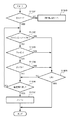
まず、本実施の形態における標準操作画面と、エコモード画面の切り換え動作について図5を参照して説明する。
【0053】
ステップS401において、後述する図7に示す標準操作画面であるか、後述する図8に示すエコモード画面であるかを判定する。標準操作画面の場合ステップS402に進み、エコモード切り換えキー2019が押下されたか判断する。押下された場合にはステップS403でエコモード画面表示に切り替え、押下されていない場合には切り換えずにそのまま終了する。
【0054】
一方、ステップS401でエコモード画面である場合、ステップS404でエコモード切り換えキー2019が押下されたか判断する。押下された場合にはステップS405で標準操作画面表示に切り替え、押下されていない場合には切り換えずにそのまま終了する。
【0055】
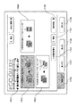
図7は操作部2012のLCD表示部2013上に表示される標準操作画面である。エコモード切り替えキー2019を押下すると、図8のエコモード画面に切り替わる。この画面では以下のような機能と設定が可能である。
【0056】
省紙設定キー701/702/703では、読み込む原稿に対して出力用紙をどのくらい節約するかという省紙モードを設定する。省トナー設定キー704はトナーを節約するための設定を行う。エコチェックキー705はこのコピー機での省エネ/省資源化の度合いをグラフで視覚的に確認する画面を呼び出す。エコガイドキー706は省紙や省トナーなどの設定をガイドに従って簡単に設定してゆく画面を呼び出す。倍率設定キー707は出力物の倍率を設定する。用紙選択キー708は出力用紙を選択する。コピープレビューキー709はキー押下でスキャナ2070で原稿の画像を読みとり、各種設定を反映させた出力プレビューを確認できる。ソーターキー710は各種ソートの設定を行うキーであり、応用モードキー711は各種応用モードを設定する。
【0057】
画面の中央には設定プレビュー712が表示され、その上部には現在の機器の状態表示713が行われる。設定プレビューには省紙設定プレビュー714、省トナープレビュー715、倍率表示716、用紙選択カセット表示717、用紙設定表示718、部数表示719、ソーター設定表示720がなされる。
【0058】
標準画面からエコモード画面に切り替えた段階の初期状態では1/2省紙(片面原稿縦→両面)と省トナー(ファインエッジドラフト)が設定されており、図8の画面上では1/2省紙キー701と省トナーキー704は他の設定キーとはボタン自体の色等、表示方法が変化して、設定されていることが容易に判別可能であるように表示をする。また、その設定内容は設定プレビュー712に714、715の様に表示される。更に、図8では、ユーザによりステイプルソートするよう選択指示されている場合を示しており、ソーター設定指示720が表示され、ソーターが設定されていることが分かるようにソーターキーのボタン自体の色などが変化する。
【0059】
図9は1/2省紙キー701を押下した時の表示画面である。この画面では原稿タイプが上段に、出力タイプが下段に配置されている。
【0060】
このモードはコピー出力される枚数が原稿の枚数に対して半分になるような設定のみが表示されており、原稿タイプに対応して出力が半分になるように出力タイプ表示が変化する。なお、正確には、原稿枚数が奇数の場合には、端数の頁が1枚として出力されるため、半分よりも多くなるが、便宜上、「半分」と表現する。
【0061】
1/2省紙キー701を押下した時のデフォルト画面では、原稿タイプが片面原稿縦801、出力タイプが両面809に設定されており、これら3つのキーは他のキーとは色等の表示方法を異なるようにし、設定されていることが分かるように表示する。なお、読み取り入力する原稿タイプは、片面原稿縦801、片面原稿横803、両面原稿縦805、両面原稿横807の中から選択でき、出力設定できるタイプは両面809、2in1 811、2in1 813、A3→A4/B4→B5縮小815である。キーの上部にはそれぞれのキーのプレビュー(802、804、806、808、810、812、814、816)が表示される。
【0062】
エコレベル表示819は1/2省紙モードがどれくらいの省エネ/省資源であるかを視覚的に示す。
【0063】
OKキー817は設定を承認するためのキーである。設定取り消しキー818は省紙機能をキャンセルするためのキーであり、設定取り消しキー818が押下されると画像形成装置の初期状態に設定される。
【0064】
図10は1/2省紙モードで、原稿タイプとして片面原稿横803を選択したときの画面であり、原稿タイプのキー及びプレビュー表示は図9と同じである。出力設定できるタイプは両面901、2in1903、A3→A4/B4→B5縮小905で、それぞれのキーの上にプレビュー(902、904、906)が表示される。
【0065】
片面原稿横キー803とこのキーを押下した時のデフォルト画面では、出力タイプの初期状態である両面キー901が他のキーとは色等の表示方法が異なるようにし、設定されていることが分かるように表示する。
【0066】
図11は1/2省紙モードで、原稿タイプとして両面原稿縦805を選択したときの画面であり、初期状態では2in1両面1001が選択されている。
【0067】
図12は1/2省紙モードで、原稿タイプとして両面原稿横807を選択したときの画面で、初期状態では2in1両面1101が選択されている。出力タイプとしてはそれぞれ原稿枚数に対して出力枚数が半分になるような設定が表示される。
【0068】
図13は1/4省紙キー702を押下した時の画面で、この場合は原稿枚数に対して出力枚数が1/4になるような設定キーとプレビューのみが表示される。なお、正確には、原稿枚数が4の倍数ではない場合には、端数の頁が1枚として出力されるため、1/4よりも多くなるが、便宜上、「1/4」と表現する。初期状態では片面原稿縦1201と2in1両面1202が選択されている。以下、選択された原稿のタイプに基づいて、出力枚数を1/4にできる方法が出力タイプとして表示される。
【0069】
同様に図14は1/8省紙キー703を押下した時の画面で、この場合は原稿枚数に対して出力枚数が1/8になるような設定キーとプレビューのみが表示される。なお、正確には、原稿枚数が8の倍数ではない場合には、端数の頁が1枚として出力されるため、1/8よりも多くなるが、便宜上、「1/8」と表現する。初期状態では片面原稿縦1301と4in1両面1302が選択されている。
【0070】
図11、図12、図13、図14に示す画面においても、選択されているキーが容易に判別できるように他のキーと色等の表示方法が異なっている。
【0071】
図6は1/2省紙設定の流れを示すフローチャートである。1/4省紙や1/8省紙、トナー節約などの他のキーが選択された場合は(ステップS501でNO)、他のキー処理(ステップS506)へ進む。
【0072】
処理手順は、原稿タイプ選択手順と、出力タイプ選択手順の大きく二つのブロックに分けられる。最初に原稿タイプを選択し、その後出力タイプを選択する。
【0073】
この手順は1/2省紙設定、1/4省紙設定、1/8省紙設定に共通であるので、1/2省紙設定を例に動作を説明する。
【0074】
まず、1/2省紙キーを選択が選択されると(ステップS501でYES)、原稿タイプの設定を行う。片面原稿縦(ステップS502でYES)か、片面原稿横(ステップS503でYES)か、両面原稿縦(ステップS504でYES)か、両面原稿横(ステップS505でYES)かのいずれかを選択する。デフォルトでは片面原稿縦キーが選択されている。この時点で設定を取り消す場合は設定取り消しキー818を押下し(ステップS523でYES)、設定を取り消す。
【0075】
原稿タイプ選択でいずれかのキーを押下すると、図9乃至図12を参照して説明したように、それぞれのキーに対応した出力タイプ選択キー及びプレビューに切り替わる。
【0076】
片面原稿縦を選択した後(ステップS502でYES)、両面(ステップS507でYES)か、2in1(ステップS508でYES)か、A3→A4/B4→B5縮小(ステップS509でYES)かのいずれかを選択し、OKキー817を押下して(ステップS519)設定を完了する。この時点で設定を取り消したい場合は設定取り消しキー818を押下して(ステップS523)設定を取り消す。
【0077】
片面原稿横(ステップS503)、両面原稿縦(ステップS504)、両面原稿横(ステップS505)のそれぞれが選択された場合も同様に、図10乃至図12に示す出力タイプの各キーのいずれかを選択し(ステップS510〜S518)、OKキー817押下で設定を完了する(ステップS520〜S522)。
【0078】
設定終了後は図8の画面に戻り、中央のプレビュー表示エリア712の中の省紙プレビューエリア714に設定したプレビューが表示される。
【0079】
図15は、図8のエコモード画面において、省トナーキー704を押下したときの画面を示す。また、図16は省トナー設定の流れを示すフローチャートである。1/2省紙や1/4省紙、1/8省紙などの他のキーが選択された場合は(ステップS1501でNO)、他のキー処理(ステップS1508)へ進む。
【0080】
まず省トナーキー704が押下されると(ステップS1501でYES)、ステップS1502に進む。ここでは初期状態として「ファインエッジドラフト」が選択されており、省トナーキー704とファインエッジドラフトキー1402が他のキーと異なった色等により異なる表示状態となり、選択されていることを示している。
【0081】
ファインキー1401を押下すると(ステップS1503でYES)トナーモードは「ファイン」になり、トナーの削減効果がない通常のモードとなる。このときの印字イメージとエコレベルをプレビューとしてキーの左に表示する(1404)。ファインエッジドラフトキー1402を押下すると(ステップS1502でYES)トナーモードは「ファインエッジドラフト」になり、文字や図形の輪郭をはっきりさせ、ベタ面のみファインモードより薄く印刷するモードとなる。このときの印字イメージとエコレベルをプレビューとしてキーの左に表示する(1405)。また、ドラフトキー1403を押下すると(ステップS1504でYES)トナーモードは「ドラフト」になり、画像全体のトナー消費を抑え、ファインモードより全体に薄く印刷するモードとなる。このときの印字イメージとエコレベルをプレビューとしてキーの左に表示する(1405)。
【0082】
設定の選択を終了後、OKキー1407を押下し(ステップS1505でYES)設定を終了する。OKキー1407を押さずに(ステップS1505でNO)設定取り消しキー1408を押下すると(ステップS1506でYES)、ステップS1507でファインモード(トナー削減をしない)に設定されて終了する。
【0083】
設定終了後は図8の画面に戻り、中央のプレビュー表示エリア712の中の省トナープレビューエリア715に設定したプレビューが表示される。
【0084】
図17は図8のエコモード画面において、エコチェックキー705を押下したときに表示される画面を示す。エコチェックキー705が他のキーと異なった色等により異なる表示状態となり、選択されていることを示している。
【0085】
この画面では過去のコピーログから、どの程度の省エネ/省資源効果があったかをグラフにより視覚的に読みとれるようにするものである。
【0086】
図17において、エコレベル1601は過去に行ったコピーログから削減設定のあった用紙出力やトナーなどのカウントに任意の係数処理を行い、全体としてどの程度の省エネ/省資源効果があったかを表示するものである。コピー枚数表示1602は過去のコピーログからエコモードで出力した枚数と標準モードで出力した枚数をカウントし、グラフ表示するものである。省紙レベル1603は過去のコピーログから全出力枚数のうち、省紙設定で出力したものの割合をカウントし、グラフ表示するものである。省トナーレベル1604は過去のコピーログから全出力枚数のうち、省トナーで出力したものの割合をカウントし、グラフ表示するものである。リセットキー1605を押下すると過去のログからカウントした表示はリセットされ、初期状態に戻る。データ呼び出しキー1607を押下すると図25の画面が表示される。また、閉じるキー1606を押下すると、この画面は閉じられて図8の画面へ戻る。
【0087】
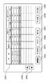
図25はデータ呼び出しキー1607を押下した時に表示される画面である。
【0088】
図25において2501は各モードでどのくらいのコピー枚数があったかを枚数表示する表である。表示内容は期間、省紙モード、省トナーモードで、ログデータを期間毎に集計して枚数表示する。期間セレクトキー2502/2503は集計期間を選択するためのキー、期間設定キー2504はログの集計を取りたい期間を設定するためのキー、データクリアキー2505は、選択されている期間のログを消去するためのキー、プリントキー2506は表2501をプリントするためのキー、閉じるキー2507はこの表示を閉じて図17のエコチェック表示へ戻るためのキーである。期間セレクトキー2502/2503により期間を選択し、閉じるキー2507を押下することにより、選択された期間の集計結果が図17に示すように表示される。また、データ前2508/データ次2509キーは表2501に現在表示されている期間以外のデータがある場合に有効なキーで、このキー操作によって過去のログデータを表示する。
【0089】
図18は、図8のエコモード画面において、エコガイドキー706を押下した時に表示される画面である。エコガイドではエコモード画面の設定がヘルプガイダンス的に設定できるのでエコモードの機能を知らないユーザでも簡単に省エネ/省資源設定が可能である。
【0090】
図18において下部に示されるキー1706〜1708はエコガイドのメニューで、タブ形式になっている。初期状態画面では省紙キー1706が選択されており、片面原稿→両面出力設定1711が設定されており、選択されていることが容易に分かるように背景の色等の表示状態が他の設定とは異なっている。この画面ではこの他に省トナー1707、省エネルギー1708の設定が可能である。閉じるキー1709はこの画面を閉じ、図8の画面へ戻るためのものである。この画面の左上には削減割合のメッセージ1710、右上には一画面前に戻るキー1701、省エネ/省資源化をさらに進める設定を呼び出すさらに節約キー1702(図18の状態で押下されると4in1の設定候補が呼び出される)が表示される。
【0091】
画面中央部分には省紙設定選択キー1711、1712、1713、1714、右下にはこの設定を使うキー1703、一つ前の画面に戻るキー1704、他の方法をガイドする他の方法キー1705が表示される。
【0092】
この画面では削減割合のメッセージ1710に「紙の使用量を1/2に減らします」と表示してあり、紙の使用量を1/2に削減可能な選択肢がプレビューと共に表示されている。1711〜1714の選択肢で現在選択されているものは他のものより背景の部分の色等の表示状態が異なっており、現在選択状態であることを示している。ここで表示されている省紙の選択肢は図9で表示されている原稿タイプと出力タイプの組み合わせであり、同じ内容である。
【0093】
さらに節約キー1702は出力用紙を1/4、1/8とさらに節約するための設定を行うキーである。このキーを押下すると図19の画面が表示される。削減割合のメッセージ1801には「紙の使用量を1/4に減らします」と表示され、1/4削減の選択肢1802、1803、1804、1805が表示される。この選択肢1802〜1805は図13で表示されている原稿タイプと出力タイプの組み合わせであり、同じ内容である。この図19でさらに節約キー1702を押下すると1/8省紙のガイダンス画面が表示される。
【0094】
また、図18で他の方法キー1705を押下すると図20の画面が表示される。
【0095】
図20の画面では削減割合のメッセージ1901に「紙の使用量を1/2に減らします」と表示してあり、省紙の選択肢1902,1903、1904が表示される。この選択肢は図10の片面原稿横キー803を押下したときの出力タイプの選択肢と同じ内容である。
【0096】
同様に他の方法キー1705を押下すると1/2省紙モードで図11,図12の内容と同様の原稿タイプ別の異なる選択肢が表示される。同様に、図19の1/4省紙画面及び不図示の1/8省紙画面で他の方法キーを押下すると、原稿タイプ別の異なる選択肢が表示される。
【0097】
以上説明したようにエコガイドの省紙設定では、さらに節約キー1702を押下してゆくことで図8の1/2省紙キー701、1/4省紙キー702、1/8省紙キー703を選択した時と同じ設定項目が表示される。
【0098】
また他の方法キー1705を押下することで、図9〜図12で説明した原稿タイプと出力タイプの組み合わせを一画面ずつ表示し設定することができる。
【0099】
図21は、図8のエコモード画面において、エコガイドキー706を押下したときの図18の画面におけるフローチャートである。
【0100】
まず省紙設定かどうかの確認を行い(ステップS2001)、他の設定であれば省トナー設定あるいは省エネ設定へ進む(ステップS2003)。省紙設定の場合は1710のメッセージで1/2省紙かの確認を行い(ステップS2002)、もっと節約したい場合はさらに節約キー1702を押下して図20のような1/4省紙設定、さらに1/8省紙設定へと進む(ステップS2004)。
【0101】
1/2省紙設定ではあるが、原稿タイプが図18に表示されているものでは無い場合は他の方法キー1705を押下して(ステップS2005)図19のような異なる原稿タイプの場合の設定に進む(ステップS2012)。図18に示す選択肢1711〜1714の中から選ぶ場合は、4つの選択肢の中から一つを選択し(ステップS2006、S2007、S2008、S2009のいずれかでYES)、この設定を使うキー1703を押下し(ステップS2010)設定を終了する。この設定を使うキー1703を押下せず閉じるキー1709を押下した場合は、エコガイドキー706を押す前の状態の設定に戻してから図8の画面に戻る。
【0102】
図22は図18の画面で省トナーキー1707を押下したときの画面である。
【0103】
この省トナーモードでの削減メッセージ2103とプレビュー2104が表示される。この設定を使う場合はこの設定を使うキー2105を押下する。これにより、図15の画面でファインエッジドラフトキー1402及びOKキー1407が押下されたのと同じ設定が為される。さらに節約したい場合はさらに節約キー2101を押下し、図23の画面へ移行する。
【0104】
図23は省トナーのドラフトモードであり、ここでこの設定を使うキー2201を押下すると、図15の画面でドラフトキー1403及びOKキー1407が押下されたのと同じ設定が為される。
【0105】
図24は、図8のエコモード画面において、コピープレビューキー709を押下したときの画面である。
【0106】
コピープレビューキー709押下でスキャナ2070が原稿の画像を読みとり、各種設定を反映させた出力プレビューを確認できる。
【0107】
これは2in1両面の出力設定した時の画面で、画面中央に各種設定を反映させたプレビュー2305、その上部に設定等のメッセージエリア2306、下部に頁をめくるためのコントロールキーが表示される。
【0108】
オート2302は複数頁のプレビューの場合、自動で頁をめくり、どの様なイメージで出力されるかを表示する。最終ページキー2303を押下すると最終ページが表示される。次ページキー2301を押下すると現在表示されている次のページが表示される。また、図24では1枚目の出力プレビューが表示されているために選択可能となっていないが、2枚目以降の出力プレビューが表示されているときには、前の頁に自動で頁をめくるオートキー、先頭頁へ進む先頭ページキー、1ページ前のページに戻る前ページキーにより所望のページをプレビューすることができる。
【0109】
また、閉じるキー2304を押下すると、図8のエコモード画面に戻る。
【0110】
なお、本実施の形態においては、省資源のための設定として1/2省紙設定、1/4省紙設定、1/8省紙設定、及び省トナー設定が実行可能である場合について説明したが、本発明はこれに限るものではなく、いずれか一つのみであっても、また、これら以外の省資源方法を用いても良く、様々な組み合わせが可能である。
【0111】
また、省トナー設定については、2段階の異なるプリント方法により省トナーを実現していたが、いずれか一方であっても、これら以外の省トナー方法を用いても良く、様々な組み合わせが可能である。
【0112】
また、本実施の形態では、ハードキーによりエコモード切り換えキーを構成したが、本発明はこれに限るものではなく、エコモード切り替えキー2019の代わりに、図7に示す標準操作画面上にエコモード画面に切り替わるソフトキーを追加し、図8に示すエコモード画面上に標準操作画面に切り替わるソフトキーを追加することにより、標準操作画面とエコモード画面とを切り換えるようにしてもよい。
【0113】
更に、本発明は、複数の機器(例えばホストコンピュータ、インターフェイス機器、スキャナ、プリンタなど)から構成されるシステムに適用しても、一つの機器からなる装置(例えば、複写機、ファクシミリ装置など)に適用してもよい。
【0114】
また、本発明の目的は、前述した実施形態の機能を実現するソフトウェアのプログラムコードを記録した記憶媒体(または記録媒体)を、システムあるいは装置に供給し、そのシステムあるいは装置のコンピュータ(またはCPUやMPU)が記憶媒体に格納されたプログラムコードを読み出し実行することによっても、達成されることは言うまでもない。この場合、記憶媒体から読み出されたプログラムコード自体が前述した実施形態の機能を実現することになり、そのプログラムコード及びプログラムコードを記憶した記憶媒体は本発明を構成することになる。また、コンピュータが読み出したプログラムコードを実行することにより、前述した実施形態の機能が実現されるだけでなく、そのプログラムコードの指示に基づき、コンピュータ上で稼働しているオペレーティングシステム(OS)などが実際の処理の一部または全部を行い、その処理によって前述した実施形態の機能が実現される場合も含まれることは言うまでもない。ここでプログラムコードを記憶する記憶媒体としては、例えば、フロッピーディスク、ハードディスク、ROM、RAM、磁気テープ、不揮発性のメモリカード、CD−ROM、CD−R、DVD、光ディスク、光磁気ディスク、MOなどが考えられる。
【0115】
さらに、記憶媒体から読み出されたプログラムコードが、コンピュータに挿入された機能拡張カードやコンピュータに接続された機能拡張ユニットに備わるメモリに書込まれた後、そのプログラムコードの指示に基づき、その機能拡張カードや機能拡張ユニットに備わるCPUなどが実際の処理の一部または全部を行い、その処理によって前述した実施形態の機能が実現される場合も含まれることは言うまでもない。
【0116】
本発明を上記記憶媒体に適用する場合、その記憶媒体には、先に説明した図6、図16、図21に示すフローチャート及び、図7乃至図24等に示す操作画面を操作部2012の表示画面2013に表示するためのプログラムコードが格納されることになる。
【0117】
【発明の効果】
以上説明したように本発明によれば、省エネ/省資源の設定方法を分かりやすく表示し、簡単な動作で省エネ/省資源の設定を行うことができる。
【図面の簡単な説明】
【図1】本発明の実施の形態における画像処理装置が接続されるネットワークシステム全体の構成例を示すブロック図である。
【図2】本発明の実施の形態における画像処理装置の全体構成を示すブロック図である。
【図3】図2に示す画像処理装置を横から見た場合の外観図である。
【図4】本発明の実施の形態における操作部の外観図である。
【図5】本発明の実施の形態における操作画面の切り換え動作を説明するフローチャートである。
【図6】本発明の実施の形態における1/2省紙選択の手順を示すフローチャートである。
【図7】本発明の実施の形態における表示部に表示される標準的モード画面を示す図である。
【図8】本発明の実施の形態における表示部に表示されるエコモード画面を示す図である。
【図9】本発明の実施の形態において、1/2省紙選択時で原稿が片面縦の時に表示部に表示される画面を示す図である。
【図10】本発明の実施の形態において、1/2省紙選択時で原稿が片面横の時に、表示部に表示される画面を示す図である。
【図11】本発明の実施の形態において、1/2省紙選択時で原稿が両面縦の時に表示部に表示される画面を示す図である。
【図12】本発明の実施の形態において、1/2省紙選択時で原稿が両面横の時に表示部に表示される画面を示す図である。
【図13】本発明の実施の形態において、1/4省紙選択時で原稿が片面縦の時に表示部に表示される画面を示す図である。
【図14】本発明の実施の形態において、1/8省紙選択時で原稿が片面縦の時に表示部に表示される画面を示す図である。
【図15】本発明の実施の形態において、省トナー選択時に表示部に表示される画面を示す図である。
【図16】本発明の実施の形態における省トナー選択の手順を示すフローチャートである。
【図17】本発明の実施の形態において、エコチェック選択時に表示部に表示される画面を示す図である。
【図18】本発明の実施の形態において、エコガイド選択時で1/2省紙、原稿が片面縦の時に表示部に表示される画面を示す図である。
【図19】本発明の実施の形態において、エコガイド選択時で1/4省紙、原稿が片面縦の時に表示部に表示される画面を示す図である。
【図20】本発明の実施の形態において、エコガイド選択時で1/2省紙、原稿が片面横の時に表示部に表示される画面を示す図である。
【図21】本発明の実施の形態において、エコガイド選択時で1/2省紙、片面原稿縦の時の選択動作を示すフローチャートである。
【図22】本発明の実施の形態において、エコガイド選択時で省トナー、ファインエッジドラフトモード選択時に表示部に表示される画面を示す図である。
【図23】本発明の実施の形態において、エコガイド選択時で省トナー、ドラフトモード選択時に表示部に表示される画面を示す図である。
【図24】本発明の実施の形態における表示部に表示されるプレビュー画面を示す図である。
【図25】本発明の実施の形態において、エコチェック選択時にデータ呼び出しを選択した場合に表示部に表示される画面を示す図である。
【符号の説明】
2012 操作部
2013 LCD表示部
2014 スタートキー
2015 ストップキー
2016 IDキー
2017 リセットキー
2018 2色LED
2019 エコモード切り換えキー
2070 スキャナ
2072 原稿フィーダ
2073 トレイ
2095 プリンタ
2101〜2104 用紙カセット
2111 排紙トレイ[0001]
BACKGROUND OF THE INVENTION
The present invention relates to an image forming apparatus, an interface apparatus for the image forming apparatus, and a setting operation method for the image forming apparatus, and more particularly, an image forming apparatus corresponding to ecology (energy saving / resource saving), and an interface to the image forming apparatus. The present invention relates to a setting operation method for an image forming apparatus and an image forming apparatus.
[0002]
[Prior art]
2. Description of the Related Art Conventionally, there are a number of ecological technologies for the purpose of saving energy and resources in image forming apparatuses.
[0003]
Under such circumstances, as a prior art regarding energy saving and operability, for example, Japanese Patent Laid-Open No. 11-52630 proposes an image forming apparatus that supports energy saving.
[0004]
The conventional technology has a double-sided printing function and a reduced layout such as 2in1 (combines two pages of originals into one page) or 4in1 (combines four pages of originals into one page). Something like functions.
[0005]
[Problems to be solved by the invention]
However, these conventional functions are often scattered and displayed on the operation panel as one function for output in the operation of the image forming apparatus. In addition, the operation screen has a deep hierarchy and is often not used effectively for reasons such as a user who does not realize that such a function is present or a complicated setting even if he / she notices it.
[0006]
In addition to the functions such as the double-sided printing function and the reduced layout function described above, reducing the image and outputting it with a paper size smaller than the original document (for example, reducing from A3 to A4) is considered as energy / resource saving. However, on the operation screen, this function is often grouped in a single function such as a zoom function or a reduction function, and is often not used effectively.
[0007]
Further, in the conventional image forming apparatus, since the user interface is not an operation interface that is conscious of energy saving / resource saving, the user can actively perform operations that lead to energy saving / resource saving. It was difficult to get.
[0008]
Further, in the conventional image forming apparatus, it has been difficult to visually check how much energy / resource saving effect the user actually has.
[0009]
Further, even in an image forming apparatus equipped with such a double-sided printing function or a reduced layout function, such energy / resource saving settings are often not noticed unless the manual is read in detail.
[0010]
The present invention has been made in view of the above problems, and an object of the present invention is to display energy saving / resource saving functions in an easy-to-understand manner, and to enable energy saving / resource saving settings with a simple operation.
[0011]
[Means for Solving the Problems]
In order to achieve the above object, an apparatus of the present invention that provides a user interface for performing settings used for image formation performed in an image forming apparatus based on image data is provided in the image formation.A plurality of predetermined paper saving amounts relative to the amount of paper used when the image data is formed without reducing the amount of paper used.Display on the displayTableDisplay control means and, The tableDisplayed by display control meansThe plurality of predetermined paper saving amountsWhatIs itSelection means for allowing the user to select,in frontRecordChoiceSelected by meansDetermination means for determining a setting item capable of realizing the paper saving amount, and the setting item sets at least any two of a duplex printing setting, a paper size reduction setting, and an image size reduction setting. The display control unit causes the display unit to display a list of setting items determined by the determination unit..
[0017]
According to a preferred aspect of the present invention,Multiple predetermined paper savings areReduce paper usageWithoutNumber of sheets required for image formation of the
[0018]
According to a preferred aspect of the present invention,Image size reductionSettingThe default isSetting item for specifying printing on one page by reducing the image data for several pagesEyesIncluding. Also,The paper size reduction setting includes a setting item for specifying printing on a paper having a smaller size by reducing the image data.
[0019]
According to the above configuration, the user can select a plurality of output patterns for the document according to the paper saving ratio.SavingResource consciousness can be raised and setting operations become easy.
[0021]
According to the above configuration, it is possible to save resources by reducing the toner density according to the desired output.
[0022]
According to a preferred aspect of the present invention,ChoiceBefore by meansTableDisplayed by the display control meansPaper savingAnd determining means for determining the degree of resource saving according to the selection ofTableThe display control means further displays the degree determined by the determination means.
[0023]
According to the above configuration, ProvinceBy displaying the degree of resources, the user can intuitively understand the degree of resource saving intuitively.
[0026]
Also, according to a preferred aspect of the present invention,The display control means further includes second selection means for allowing the user to select one of the setting items displayed in a list on the display unit, and the display control means is further selected by the second selection means. TheThe output state of the image data obtained when image formation is performed based on the selection item is displayed on the display unit before the image formation.Ru.
[0027]
According to the above configuration, mis-copying can be reduced by previewing settings and output before copying.
[0031]
Further, the user interface display method of the present invention for performing settings used for image formation performed by the image forming apparatus based on image data is as follows:The display control meansIn the image formationA plurality of predetermined paper saving amounts relative to the amount of paper used when the image data is formed without reducing the amount of paper used.Display on the displayTableDisplay control process;By means of selectionin frontTableDisplayed by the control processSelection that allows the user to select one of the plurality of predetermined paper saving amountsProcess,The judging meansAboveChoiceIn the processAchieving the selected paper saving amountSetting itemsJudgmentDoJudgmentA process,The setting item includes an item for setting at least any two of a duplex printing setting, a paper size reduction setting, and an image size reduction setting. In the display control step, the setting item is determined in the determination step. List the set items on the display unit.
[0032]
DETAILED DESCRIPTION OF THE INVENTION
Preferred embodiments of the present invention will be described below in detail with reference to the accompanying drawings.
[0033]
<Entire system>
FIG. 1 is a block diagram showing an example of the configuration of a network system to which an image input apparatus of the present invention is connected. An
[0034]
[0035]
<Configuration of image processing apparatus>
Next, the configuration of the
[0036]
First, the overall configuration of the
[0037]
The
[0038]
A control program for controlling various processes executed by the
[0039]
An operation unit I /
[0040]
The above devices are arranged on the
[0041]
An image bus I /
[0042]
The
[0043]
A raster image processor (RIP) 2060 expands the PDL code into a bitmap image. The device I /
[0044]
The
[0045]
In the configuration as described above, the configuration connected to the
[0046]
FIG. 3 is an external view of the
[0047]
A
[0048]
The
[0049]
The
[0050]
A
[0051]
Next, a screen displayed on the
[0052]
First, the switching operation between the standard operation screen and the eco mode screen in the present embodiment will be described with reference to FIG.
[0053]
In step S401, it is determined whether the screen is a standard operation screen shown in FIG. 7 described later or an eco mode screen shown in FIG. 8 described later. In the case of the standard operation screen, the process proceeds to step S402, and it is determined whether the eco mode switching key 2019 is pressed. If pressed, the screen is switched to the eco mode screen display in step S403, and if not pressed, the process is terminated without switching.
[0054]
On the other hand, if the screen is the eco mode screen in step S401, it is determined in step S404 whether the eco mode switching key 2019 has been pressed. If it has been pressed, the display is switched to the standard operation screen display in step S405, and if it has not been pressed, the process is terminated without switching.
[0055]
FIG. 7 is a standard operation screen displayed on the
[0056]
With a paper saving setting key 701/702/703, a paper saving mode is set for how much output paper is saved for a document to be read. A toner save setting
[0057]
A
[0058]
In the initial state when the standard screen is switched to the eco mode screen, 1/2 paper saving (vertical → double-sided original) and toner saving (fine edge draft) are set. On the screen in FIG. The
[0059]
FIG. 9 shows a display screen when the 1/2
[0060]
In this mode, only the setting is made such that the number of copies output is halved with respect to the number of documents, and the output type display changes so that the output is halved corresponding to the document type. To be precise, when the number of originals is an odd number, a fractional page is output as one sheet, which is more than half, but is expressed as “half” for convenience.
[0061]
In the default screen when the 1/2 paper-saving
[0062]
The
[0063]
An
[0064]
FIG. 10 is a screen when the one-side
[0065]
In the default screen when the single-sided document
[0066]
FIG. 11 is a screen when the double-sided
[0067]
FIG. 12 shows a screen when 1/2 paper saving mode is selected and double side original 807 is selected as the original type. In the initial state, 2in1
[0068]
FIG. 13 shows a screen when the 1/4 paper-saving
[0069]
Similarly, FIG. 14 shows a screen when the 1/8 paper-saving
[0070]
In the screens shown in FIGS. 11, 12, 13, and 14, the display method of colors and the like is different from other keys so that the selected key can be easily identified.
[0071]
FIG. 6 is a flowchart showing the flow of 1/2 paper saving setting. If another key such as 1/4 paper saving, 1/8 paper saving, or toner saving is selected (NO in step S501), the process proceeds to another key process (step S506).
[0072]
The processing procedure is roughly divided into two blocks: a document type selection procedure and an output type selection procedure. First, the document type is selected, and then the output type is selected.
[0073]
Since this procedure is common to 1/2 paper saving setting, 1/4 paper saving setting, and 1/8 paper saving setting, the operation will be described by taking 1/2 paper saving setting as an example.
[0074]
First, when selection of 1/2 paper saving key is selected (YES in step S501), the document type is set. Select either one-sided document length (YES in step S502), one-sided document width (YES in step S503), double-sided document length (YES in step S504), or double-sided document width (YES in step S505). By default, the single-sided document vertical key is selected. When canceling the setting at this time, the setting cancel key 818 is pressed (YES in step S523), and the setting is cancelled.
[0075]
When any key is pressed in the document type selection, as described with reference to FIGS. 9 to 12, the output type selection key and the preview corresponding to each key are switched.
[0076]
After selecting single-sided original length (YES in step S502), either double-sided (YES in step S507), 2in1 (YES in step S508), or A3 → A4 / B4 → B5 reduction (YES in step S509) And press the OK key 817 (step S519) to complete the setting. If it is desired to cancel the setting at this time, the setting cancel key 818 is pressed (step S523) to cancel the setting.
[0077]
Similarly, when each of the single-side original side (step S503), double-side original side (step S504), and double-side original side (step S505) is selected, any one of the output type keys shown in FIGS. Selection is made (steps S510 to S518), and the setting is completed by pressing the OK key 817 (steps S520 to S522).
[0078]
After the setting is completed, the screen returns to the screen of FIG. 8 and the preview set in the paper saving
[0079]
FIG. 15 shows a screen when the toner save
[0080]
First, when the toner save
[0081]
When the
[0082]
After the selection of the setting is completed, an
[0083]
After the setting is completed, the screen returns to the screen of FIG. 8 and the preview set in the toner saving
[0084]
FIG. 17 shows a screen displayed when the
[0085]
This screen allows you to visually read from the past copy log how much energy / resource saving effect there was.
[0086]
In FIG. 17, the
[0087]
FIG. 25 shows a screen displayed when the data call key 1607 is pressed.
[0088]
In FIG. 25, a table 2501 displays how many copies have been made in each mode. The displayed contents are a period, a paper saving mode, and a toner saving mode, and the log data is totaled for each period and the number of sheets is displayed. A period select key 2502/2503 is a key for selecting a total period, a period setting key 2504 is a key for setting a period for which logs are to be totaled, and a data clear key 2505 is for deleting a log for the selected period. A
[0089]
FIG. 18 is a screen displayed when the
[0090]
In FIG. 18,
[0091]
Paper saving
[0092]
In this screen, the
[0093]
Further, a saving key 1702 is a key for setting for further saving the output paper to 1/4 and 1/8. When this key is pressed, the screen of FIG. 19 is displayed. The
[0094]
When another
[0095]
In the screen of FIG. 20, the
[0096]
Similarly, when the other method key 1705 is pressed, different options for each document type are displayed in the 1/2 paper-saving mode, similar to the contents shown in FIGS. Similarly, when another method key is pressed on the 1/4 paper saving screen in FIG. 19 and the 1/8 paper saving screen (not shown), different options for each document type are displayed.
[0097]
As described above, in the eco-guide paper saving setting, when the saving key 1702 is further pressed, the 1/2 paper saving key 701, the 1/4 paper saving key 702, and the 1/8 paper saving key 703 in FIG. The same setting items are displayed as when is selected.
[0098]
By pressing another
[0099]
FIG. 21 is a flowchart of the screen of FIG. 18 when the
[0100]
First, it is confirmed whether or not the paper saving setting is set (step S2001), and if it is any other setting, the process proceeds to the toner saving setting or the energy saving setting (step S2003). In the case of paper saving setting, a
[0101]
If the original paper type is not the one shown in FIG. 18 in the case of 1/2 paper-saving setting, the other method key 1705 is pressed (step S2005) and the setting is made for different original types as shown in FIG. (Step S2012). When selecting from the
[0102]
FIG. 22 is a screen when the toner save key 1707 is pressed on the screen of FIG.
[0103]
A
[0104]
FIG. 23 shows a toner-saving draft mode. When a key 2201 that uses this setting is pressed, the same setting as when the
[0105]
FIG. 24 is a screen when the
[0106]
When the
[0107]
This is a screen when 2in1 duplex output is set. A
[0108]
In the case of a preview of a plurality of pages, the
[0109]
When the close key 2304 is pressed, the screen returns to the eco mode screen of FIG.
[0110]
In this embodiment, the case where 1/2 paper saving setting, 1/4 paper saving setting, 1/8 paper saving setting, and toner saving setting can be executed as resource saving settings has been described. However, the present invention is not limited to this, and any one of them or a resource saving method other than these may be used, and various combinations are possible.
[0111]
Regarding toner saving settings, toner saving was realized by two different printing methods, but either one or other toner saving methods may be used, and various combinations are possible. is there.
[0112]
In the present embodiment, the eco-mode switching key is configured by a hard key. However, the present invention is not limited to this, and instead of the eco-mode switching key 2019, the eco-mode is displayed on the standard operation screen shown in FIG. A soft key for switching to the screen may be added, and a soft key for switching to the standard operation screen may be added to the eco mode screen shown in FIG. 8 to switch between the standard operation screen and the eco mode screen.
[0113]
Furthermore, the present invention can be applied to a system (for example, a copier, a facsimile machine, etc.) consisting of a single device even if it is applied to a system composed of a plurality of devices (eg, host computer, interface device, scanner, printer, etc.). You may apply.
[0114]
Another object of the present invention is to supply a storage medium (or recording medium) in which a program code of software that realizes the functions of the above-described embodiments is recorded to a system or apparatus, and the computer (or CPU or CPU) of the system or apparatus. Needless to say, this can also be achieved by the MPU) reading and executing the program code stored in the storage medium. In this case, the program code itself read from the storage medium realizes the functions of the above-described embodiments, and the storage medium storing the program code and the program code constitutes the present invention. Further, by executing the program code read by the computer, not only the functions of the above-described embodiments are realized, but also an operating system (OS) running on the computer based on the instruction of the program code. It goes without saying that a case where the function of the above-described embodiment is realized by performing part or all of the actual processing and the processing is included. Examples of the storage medium for storing the program code include a floppy disk, hard disk, ROM, RAM, magnetic tape, nonvolatile memory card, CD-ROM, CD-R, DVD, optical disk, magneto-optical disk, MO, and the like. Can be considered.
[0115]
Furthermore, after the program code read from the storage medium is written into a memory provided in a function expansion card inserted into the computer or a function expansion unit connected to the computer, the function is determined based on the instruction of the program code. It goes without saying that the CPU or the like provided in the expansion card or the function expansion unit performs part or all of the actual processing and the functions of the above-described embodiments are realized by the processing.
[0116]
When the present invention is applied to the above storage medium, the storage medium displays the flowcharts shown in FIGS. 6, 16, and 21 and the operation screens shown in FIGS. Program codes to be displayed on the
[0117]
【The invention's effect】
As described above, according to the present invention, an energy saving / resource saving setting method can be displayed in an easy-to-understand manner, and energy saving / resource saving can be set with a simple operation.
[Brief description of the drawings]
FIG. 1 is a block diagram illustrating a configuration example of an entire network system to which an image processing apparatus according to an embodiment of the present invention is connected.
FIG. 2 is a block diagram showing an overall configuration of an image processing apparatus according to an embodiment of the present invention.
3 is an external view of the image processing apparatus shown in FIG. 2 when viewed from the side.
FIG. 4 is an external view of an operation unit in the embodiment of the present invention.
FIG. 5 is a flowchart illustrating an operation screen switching operation according to the embodiment of the present invention.
FIG. 6 is a flowchart showing a 1/2 paper-saving selection procedure in the embodiment of the present invention.
FIG. 7 is a diagram showing a standard mode screen displayed on the display unit in the embodiment of the present invention.
FIG. 8 is a diagram showing an eco mode screen displayed on the display unit in the embodiment of the present invention.
FIG. 9 is a diagram showing a screen displayed on the display unit when the half-paper saving is selected and the original is single-sided vertically in the embodiment of the present invention.
FIG. 10 is a diagram showing a screen displayed on the display unit when a 1/2 paper saving is selected and the original is on one side when in the embodiment of the present invention.
FIG. 11 is a diagram showing a screen displayed on the display unit when a 1/2 paper-saving mode is selected and the original is double-sided vertically in the embodiment of the present invention.
FIG. 12 is a diagram showing a screen displayed on the display unit when the original is on both sides when 1/2 paper saving is selected in the embodiment of the present invention.
FIG. 13 is a diagram showing a screen displayed on the display unit when the 1/4 paper saving is selected and the original is vertically on one side in the embodiment of the present invention.
FIG. 14 is a diagram illustrating a screen displayed on the display unit when 1/8 paper saving is selected and the original is single-sided vertically in the embodiment of the present invention.
FIG. 15 is a diagram showing a screen displayed on the display unit when toner saving is selected in the embodiment of the present invention.
FIG. 16 is a flowchart showing a toner saving selection procedure according to the embodiment of the present invention.
FIG. 17 is a diagram showing a screen displayed on the display unit when eco-check is selected in the embodiment of the present invention.
FIG. 18 is a diagram showing a screen displayed on the display unit when the eco-guide is selected in the embodiment of the present invention when 1/2 paper saving is performed and the original is vertically on one side.
FIG. 19 is a diagram showing a screen displayed on the display unit when the eco-guide is selected in the embodiment of the present invention when ¼ paper is saved and the original is vertically on one side.
FIG. 20 is a diagram showing a screen displayed on the display unit when the eco-guide is selected in the embodiment of the present invention when 1/2 paper saving is performed and the original is on one side.
FIG. 21 is a flowchart showing a selection operation when the eco-guide is selected and when 1/2 paper saving and single-sided original portrait are selected in the embodiment of the present invention.
FIG. 22 is a diagram showing a screen displayed on the display unit when toner saving and fine edge draft mode are selected when the eco guide is selected in the embodiment of the present invention.
FIG. 23 is a diagram illustrating a screen displayed on the display unit when the eco-guide is selected and the toner saving and draft mode is selected in the embodiment of the present invention.
FIG. 24 is a diagram showing a preview screen displayed on the display unit in the embodiment of the present invention.
FIG. 25 is a diagram showing a screen displayed on the display unit when data call is selected when eco-check is selected in the embodiment of the present invention.
[Explanation of symbols]
2012 Operation unit
2013 LCD display
2014 start key
2015 stop key
2016 ID key
2017 Reset key
2018 2-color LED
2019 Eco mode switch key
2070 scanner
2072 Document Feeder
2073 tray
2095 Printer
2101 to 2104 Paper cassette
2111 Output tray
Claims (9)
前記画像形成において、紙の使用量を削減せずに前記画像データを画像形成した場合に必要な紙の使用量に対する、複数の所定の省紙量を表示部に表示させる表示制御手段と、
前記表示制御手段により表示された前記複数の所定の省紙量の何れかをユーザに選択させる選択手段と、
前記選択手段により選択された省紙量を実現可能な設定項目を判定する判定手段とを有し、
前記設定項目は、両面印刷設定と、紙サイズ削減設定と、画像サイズ削減設定の内の少なくともいずれか2つを設定するための項目を含み、
前記表示制御手段は、前記判定手段により判定された設定項目を前記表示部に一覧表示させることを特徴とする装置。An apparatus for providing a user interface for performing settings used for image formation performed in an image forming apparatus based on image data,
In the image forming, for the amount of paper required when image formation of the image data without reducing the amount of paper used, and Table示制control means Ru is displayed on the display unit a plurality of predetermined saving paper weight ,
A selecting means for selecting what Re of the plurality of predetermined saving paper value displayed by the table示制control means to the user,
The pre-Symbol setting items that can realize the reduction paper amount selected by the selection means and a determination means,
The setting item includes an item for setting at least any two of a duplex printing setting, a paper size reduction setting, and an image size reduction setting,
The display control unit causes the display unit to display a list of setting items determined by the determination unit.
前記表示制御手段は、前記判定手段により判定された度合いを更に表示することを特徴とする請求項1乃至4のいずれか1項に記載の装置。Depending on the choice of Shokamiryou displayed by prior Symbol Table示制control means by said selection means, further comprising a determination means for determining the degree of resource saving,
Before Symbol Table示制control means, Apparatus according to any one of claims 1 to 4, characterized in that further displays a degree determined by the determination means.
前記表示制御手段は、更に、前記第2の選択手段により選択された選択項目に基づいて画像形成を行った場合に得られる前記画像データの出力状態を、前記画像形成前に前記表示部に表示させることを特徴とする請求項1乃至5のいずれか1項に記載の装置。 A second selection unit that allows the user to select one of the setting items displayed in a list on the display unit by the display control unit;
The display control means further displays the output state of the image data obtained when image formation is performed based on the selection item selected by the second selection means on the display unit before the image formation. apparatus according to any one of claims 1 to 5, wherein the Ruco is.
前記装置による設定を用いて、画像データに基づく画像形成を行う画像形成手段と
を有することを特徴とする画像形成装置。An apparatus according to any one of claims 1 to 6 ;
An image forming apparatus comprising: an image forming unit configured to form an image based on image data using the setting by the apparatus.
表示制御手段が、前記画像形成において、紙の使用量を削減せずに前記画像データを画像形成した場合に必要な紙の使用量に対する、複数の所定の省紙量を表示部に表示させる表示制御工程と、
選択手段により、前記表示制御工程により表示された前記複数の所定の省紙量の何れかをユーザに選択させる選択工程と、
判定手段が、前記選択工程において選択された省紙量を実現可能な設定項目を判定する判定工程とを有し、
前記設定項目は、両面印刷設定と、紙サイズ削減設定と、画像サイズ削減設定との内の少なくともいずれか2つを設定するための項目を含み、
前記表示制御工程では、前記判定工程において判定された設定項目を前記表示部に一覧表示させることを特徴とする表示方法。A display method of a user interface for performing settings used for image formation performed in an image forming apparatus based on image data,
Display control means, in the image forming, the relative amount of paper used required when the image data was imaged, Ru is displayed on the display unit a plurality of predetermined saving paper weight without reducing the amount of paper and Table示制your process,
By the selection means, a selection step of selecting one of the pre-Symbol Table示制said plurality of predetermined saving paper value displayed by your process to the user,
Determination means, and a determination step of determining a setting item which can realize the reduction of paper weight as Oite selected to the selection process,
The setting item includes an item for setting at least any two of a duplex printing setting, a paper size reduction setting, and an image size reduction setting,
In the display control step, a list of the setting items determined in the determination step is displayed on the display unit .
Priority Applications (3)
| Application Number | Priority Date | Filing Date | Title |
|---|---|---|---|
| JP2000379121A JP4480114B2 (en) | 2000-12-13 | 2000-12-13 | Image forming apparatus, apparatus for providing user interface, and display method |
| EP01310346A EP1215877A3 (en) | 2000-12-13 | 2001-12-11 | Image forming apparatus, interface apparatus, control apparatus, image forming apparatus setting operation method, and control method |
| US10/012,408 US7062190B2 (en) | 2000-12-13 | 2001-12-12 | Image forming apparatus, interface apparatus, control apparatus, image forming apparatus setting operation method, and control method |
Applications Claiming Priority (1)
| Application Number | Priority Date | Filing Date | Title |
|---|---|---|---|
| JP2000379121A JP4480114B2 (en) | 2000-12-13 | 2000-12-13 | Image forming apparatus, apparatus for providing user interface, and display method |
Publications (3)
| Publication Number | Publication Date |
|---|---|
| JP2002182529A JP2002182529A (en) | 2002-06-26 |
| JP2002182529A5 JP2002182529A5 (en) | 2008-01-31 |
| JP4480114B2 true JP4480114B2 (en) | 2010-06-16 |
Family
ID=18847560
Family Applications (1)
| Application Number | Title | Priority Date | Filing Date |
|---|---|---|---|
| JP2000379121A Expired - Fee Related JP4480114B2 (en) | 2000-12-13 | 2000-12-13 | Image forming apparatus, apparatus for providing user interface, and display method |
Country Status (3)
| Country | Link |
|---|---|
| US (1) | US7062190B2 (en) |
| EP (1) | EP1215877A3 (en) |
| JP (1) | JP4480114B2 (en) |
Families Citing this family (59)
| Publication number | Priority date | Publication date | Assignee | Title |
|---|---|---|---|---|
| KR100380250B1 (en) | 2000-02-21 | 2003-04-18 | 트렉 2000 인터네셔널 엘티디. | A Portable Data Storage Device |
| ATE335236T1 (en) | 2001-06-28 | 2006-08-15 | Trek 2000 Int Ltd | DATA TRANSFER PROCEDURES AND FACILITIES |
| US6608978B2 (en) * | 2001-12-19 | 2003-08-19 | Xerox Corporation | Paper-saving methods for printing a document |
| TW588243B (en) | 2002-07-31 | 2004-05-21 | Trek 2000 Int Ltd | System and method for authentication |
| US20040212825A1 (en) * | 2002-10-03 | 2004-10-28 | Seiko Epson Corporation | Printing apparatus and printing method |
| US7148977B2 (en) * | 2002-10-08 | 2006-12-12 | Hewlett-Packard Development Company, L.P. | Consumable availability with print preview |
| KR100729309B1 (en) * | 2003-05-14 | 2007-06-19 | 캐논 가부시끼가이샤 | Image forming apparatus, cartridge, and storing device mounted to the cartridge |
| JP4439994B2 (en) * | 2003-05-14 | 2010-03-24 | キヤノン株式会社 | Image forming apparatus, cartridge, and storage device mounted on cartridge |
| JP4402540B2 (en) * | 2004-08-06 | 2010-01-20 | キヤノン株式会社 | Image processing system, control method therefor, and program |
| US20070076235A1 (en) * | 2005-09-19 | 2007-04-05 | Kabushiki Kaisha Toshiba | Image forming apparatus and printing method thereof |
| US20070211264A1 (en) * | 2006-03-09 | 2007-09-13 | Kabushiki Kaisha Toshiba | Image forming apparatus |
| US8174727B2 (en) * | 2006-03-09 | 2012-05-08 | Kabushiki Kaisha Toshiba | Image forming apparatus that displays finished graphical image indicating multiple draft images arranged in matrix form |
| JP4386047B2 (en) | 2006-03-24 | 2009-12-16 | ブラザー工業株式会社 | Image processing apparatus and program |
| JP4068119B2 (en) * | 2006-07-25 | 2008-03-26 | シャープ株式会社 | Video display device, video display method, video display program, and recording medium |
| JP2008046159A (en) * | 2006-08-10 | 2008-02-28 | Konica Minolta Business Technologies Inc | Image forming apparatus, printing condition setting method, and printing condition setting program |
| JP5135963B2 (en) * | 2006-10-04 | 2013-02-06 | セイコーエプソン株式会社 | Image storage system |
| US20080155412A1 (en) * | 2006-12-20 | 2008-06-26 | Microsoft Corporation | Quick reference card and on-line help for a computing system |
| JPWO2008081945A1 (en) | 2006-12-28 | 2010-04-30 | 京セラ株式会社 | Portable information terminal |
| JP2009175529A (en) * | 2008-01-25 | 2009-08-06 | Sharp Corp | Image forming device |
| KR101496439B1 (en) * | 2008-08-22 | 2015-02-27 | 삼성전자주식회사 | Image forming apparatus and resource saving mode control method thereof |
| EP2157776A1 (en) * | 2008-08-22 | 2010-02-24 | Samsung Electronics Co., Ltd. | Image forming apparatus and resource saving mode control method thereof |
| US9303878B2 (en) | 2008-09-15 | 2016-04-05 | General Electric Company | Hybrid range and method of use thereof |
| US8541719B2 (en) * | 2008-09-15 | 2013-09-24 | General Electric Company | System for reduced peak power consumption by a cooking appliance |
| US8803040B2 (en) * | 2008-09-15 | 2014-08-12 | General Electric Company | Load shedding for surface heating units on electromechanically controlled cooking appliances |
| WO2010031025A1 (en) * | 2008-09-15 | 2010-03-18 | General Electric Company | Energy management of household appliances |
| US8843242B2 (en) * | 2008-09-15 | 2014-09-23 | General Electric Company | System and method for minimizing consumer impact during demand responses |
| US20100073706A1 (en) * | 2008-09-22 | 2010-03-25 | Konica Minolta Systems Laboratory, Inc. | Printing of proof copy with reduced resource usage in a print shop management system |
| US9058140B2 (en) * | 2009-03-10 | 2015-06-16 | Canon Kabushiki Kaisha | Print control apparatus and method utilizing a paper saving print setting |
| JP4869379B2 (en) * | 2009-04-20 | 2012-02-08 | シャープ株式会社 | Print control program, print control method, and print system |
| JP4875727B2 (en) | 2009-05-18 | 2012-02-15 | シャープ株式会社 | Information processing apparatus for processing information on functions combined with one function and image forming apparatus including the information processing apparatus |
| JP2010268346A (en) | 2009-05-18 | 2010-11-25 | Sharp Corp | Image forming apparatus displaying information related to function combined with one function |
| JP4875726B2 (en) | 2009-05-18 | 2012-02-15 | シャープ株式会社 | Information processing apparatus for processing information on functions combined with one function and image forming apparatus including the information processing apparatus |
| US8885181B2 (en) | 2009-08-04 | 2014-11-11 | Electronics For Imaging, Inc. | Virtual press run |
| US8934119B2 (en) | 2009-08-04 | 2015-01-13 | Electronics For Imaging, Inc. | Greenbooks |
| JP4769890B2 (en) * | 2009-08-13 | 2011-09-07 | シャープ株式会社 | Information processing apparatus, printing system, and printing control method |
| JP4839397B2 (en) * | 2009-08-25 | 2011-12-21 | シャープ株式会社 | Printing system |
| JP4574732B1 (en) | 2009-08-27 | 2010-11-04 | キヤノン株式会社 | Electrophotographic image forming apparatus |
| US8522579B2 (en) * | 2009-09-15 | 2013-09-03 | General Electric Company | Clothes washer demand response with dual wattage or auxiliary heater |
| US8869569B2 (en) * | 2009-09-15 | 2014-10-28 | General Electric Company | Clothes washer demand response with at least one additional spin cycle |
| US8943845B2 (en) | 2009-09-15 | 2015-02-03 | General Electric Company | Window air conditioner demand supply management response |
| US8943857B2 (en) * | 2009-09-15 | 2015-02-03 | General Electric Company | Clothes washer demand response by duty cycling the heater and/or the mechanical action |
| US8503030B2 (en) | 2009-09-28 | 2013-08-06 | Csr Imaging Us, Lp | Preview of a document with printable components at a printing device based on its printing capability |
| KR101532293B1 (en) * | 2009-11-13 | 2015-07-01 | 삼성전자주식회사 | Image forming apparatus and resource saving mode control method thereof |
| KR101414477B1 (en) | 2009-12-09 | 2014-07-04 | 삼성전자주식회사 | Image forming apparatus and image forming method and thereof |
| JP2011151777A (en) * | 2009-12-25 | 2011-08-04 | Canon Finetech Inc | Image processing method, and image processing apparatus |
| US20130018520A1 (en) * | 2010-02-23 | 2013-01-17 | Eungdal Kim | Execution method of one function of a plurality of functions at a component |
| JP5532316B2 (en) * | 2010-04-26 | 2014-06-25 | 村田機械株式会社 | Computer program and terminal device |
| JP2012043406A (en) * | 2010-07-23 | 2012-03-01 | Ricoh Co Ltd | Image processing apparatus, image processing method and program |
| US8801862B2 (en) | 2010-09-27 | 2014-08-12 | General Electric Company | Dishwasher auto hot start and DSM |
| JP5234097B2 (en) * | 2010-12-16 | 2013-07-10 | コニカミノルタビジネステクノロジーズ株式会社 | Image forming apparatus, display control apparatus, and program |
| KR20120095242A (en) * | 2011-02-18 | 2012-08-28 | 삼성전자주식회사 | Print controling terminal and method for controling print |
| US8937744B1 (en) | 2011-07-30 | 2015-01-20 | PrintEco, Inc. | Modifying electronic data layout for efficient printing of electronic data |
| JP2013073035A (en) | 2011-09-28 | 2013-04-22 | Seiko Epson Corp | Printer, print control device, print control method, and print control program |
| JP2014059689A (en) * | 2012-09-18 | 2014-04-03 | Konica Minolta Inc | Print condition recommendation device and print processor |
| JP6075127B2 (en) | 2013-03-07 | 2017-02-08 | ブラザー工業株式会社 | Information processing program, information processing apparatus, and information processing method |
| KR20160016458A (en) * | 2014-08-05 | 2016-02-15 | 삼성전자주식회사 | Print control apparatus, printing control method, image forming apparatus, image forming method and computer-readable recording medium |
| JP2016048879A (en) * | 2014-08-28 | 2016-04-07 | キヤノン株式会社 | Image forming apparatus, control method of image forming apparatus, and program |
| JP2017062667A (en) * | 2015-09-25 | 2017-03-30 | 富士ゼロックス株式会社 | Information processing apparatus, image forming system, and program |
| JP7024398B2 (en) * | 2017-12-27 | 2022-02-24 | 株式会社リコー | Information processing equipment, information processing methods, and information processing programs |
Citations (5)
| Publication number | Priority date | Publication date | Assignee | Title |
|---|---|---|---|---|
| JPH0619257A (en) * | 1992-06-30 | 1994-01-28 | Ricoh Co Ltd | Image forming device |
| JPH09244477A (en) * | 1996-03-13 | 1997-09-19 | Mita Ind Co Ltd | Image forming device |
| JPH1152630A (en) * | 1997-07-31 | 1999-02-26 | Ricoh Co Ltd | Image forming device |
| JPH11259264A (en) * | 1998-03-10 | 1999-09-24 | Canon Inc | Printer driver for image forming device, image forming device, and control method for image forming device |
| JP2000201248A (en) * | 1998-10-29 | 2000-07-18 | Canon Inc | Picture storage device, control method and storage medium |
Family Cites Families (18)
| Publication number | Priority date | Publication date | Assignee | Title |
|---|---|---|---|---|
| US4682158A (en) * | 1984-03-23 | 1987-07-21 | Ricoh Company, Ltd. | Guidance device for manipulation of machine |
| KR0128168B1 (en) * | 1993-12-18 | 1998-04-04 | 김광호 | Paper saving device for printer |
| US5459556A (en) * | 1994-01-12 | 1995-10-17 | Xerox Corporation | Toner consumption rate gauge for printers and copiers |
| US5528732A (en) * | 1994-10-17 | 1996-06-18 | Xerox Corporation | Reprographic device for making copies with multi-spaced lines |
| JPH08248805A (en) * | 1995-03-07 | 1996-09-27 | Mita Ind Co Ltd | Fixing part temperature controller for image forming device |
| JPH09130577A (en) * | 1995-10-30 | 1997-05-16 | Minolta Co Ltd | Image forming device |
| JP3561070B2 (en) | 1996-02-01 | 2004-09-02 | 彰 水野 | Dust removal method and dust removal sheet |
| JPH09323457A (en) * | 1996-06-06 | 1997-12-16 | Canon Inc | Printing system and print controlling method |
| JPH09327942A (en) * | 1996-06-07 | 1997-12-22 | Canon Inc | Image outputting device and its control method |
| JP3683386B2 (en) | 1996-07-03 | 2005-08-17 | 株式会社リコー | Electrophotographic liquid developer, method for producing the same, and image forming method |
| JP3428323B2 (en) * | 1996-10-25 | 2003-07-22 | ミノルタ株式会社 | Image processing system |
| NL1005272C2 (en) * | 1997-02-14 | 1998-08-18 | Oce Tech Bv | Reproduction device for copying, scanning or printing image information with an improved operating interface. |
| US5802420A (en) * | 1997-05-12 | 1998-09-01 | Lexmark International, Inc. | Method and apparatus for predicting and displaying toner usage of a printer |
| US5950045A (en) * | 1997-06-20 | 1999-09-07 | Sharp Kabushiki Kaisha | Input device |
| JP3408124B2 (en) * | 1997-11-06 | 2003-05-19 | シャープ株式会社 | Print processing device using computer system |
| JP3469079B2 (en) * | 1998-03-23 | 2003-11-25 | シャープ株式会社 | Image forming device |
| US6266153B1 (en) * | 1998-05-12 | 2001-07-24 | Xerox Corporation | Image forming device having a reduced toner consumption mode |
| JP2000331177A (en) * | 1999-05-17 | 2000-11-30 | Fuji Xerox Co Ltd | Image editing method and device |
-
2000
- 2000-12-13 JP JP2000379121A patent/JP4480114B2/en not_active Expired - Fee Related
-
2001
- 2001-12-11 EP EP01310346A patent/EP1215877A3/en not_active Withdrawn
- 2001-12-12 US US10/012,408 patent/US7062190B2/en not_active Expired - Fee Related
Patent Citations (5)
| Publication number | Priority date | Publication date | Assignee | Title |
|---|---|---|---|---|
| JPH0619257A (en) * | 1992-06-30 | 1994-01-28 | Ricoh Co Ltd | Image forming device |
| JPH09244477A (en) * | 1996-03-13 | 1997-09-19 | Mita Ind Co Ltd | Image forming device |
| JPH1152630A (en) * | 1997-07-31 | 1999-02-26 | Ricoh Co Ltd | Image forming device |
| JPH11259264A (en) * | 1998-03-10 | 1999-09-24 | Canon Inc | Printer driver for image forming device, image forming device, and control method for image forming device |
| JP2000201248A (en) * | 1998-10-29 | 2000-07-18 | Canon Inc | Picture storage device, control method and storage medium |
Also Published As
| Publication number | Publication date |
|---|---|
| JP2002182529A (en) | 2002-06-26 |
| EP1215877A2 (en) | 2002-06-19 |
| EP1215877A3 (en) | 2004-12-01 |
| US7062190B2 (en) | 2006-06-13 |
| US20020071689A1 (en) | 2002-06-13 |
Similar Documents
| Publication | Publication Date | Title |
|---|---|---|
| JP4480114B2 (en) | Image forming apparatus, apparatus for providing user interface, and display method | |
| US11115545B2 (en) | Image forming apparatus and method of information display | |
| US10268934B2 (en) | Operation console enabling appropriate selection of operational mode by the user, electronic device and image processing apparatus provided with the operation console, and method of displaying information on the operation console | |
| JP4897509B2 (en) | Image processing apparatus, preview image display method, and preview image display program | |
| US8625118B2 (en) | Display operation device having functions distinguished by colors of operation buttons, and image processing apparatus adopting the display operation device | |
| US20120105891A1 (en) | Image Processing Apparatus, Computer Program Product, and Preview Image Displaying Method | |
| JP5252910B2 (en) | INPUT DEVICE, INPUT DEVICE CONTROL METHOD, AND PROGRAM | |
| JP2007185946A (en) | Information processor, program and preview image display method | |
| JP5101672B2 (en) | Image forming apparatus | |
| JP2008219735A (en) | Image processing apparatus, program and preview image display method | |
| JP2011198164A (en) | Operation device, electronic apparatus and image processing apparatus including the operation device, and information display method of the operation device | |
| JP2008203439A (en) | Image processor, preview image display method, and preview image display program | |
| US20070076235A1 (en) | Image forming apparatus and printing method thereof | |
| JP5674427B2 (en) | Image processing device | |
| JP6309070B2 (en) | Image processing device | |
| JP5584014B2 (en) | Image processing device | |
| JP2011164836A (en) | Display device, electronic apparatus including the same, and image processing apparatus | |
| JP2015041220A (en) | Image forming apparatus | |
| JP2007249546A (en) | Data processor, data processing method, program and storage medium | |
| JP6698810B2 (en) | Processor and image forming apparatus including the same | |
| JP6907370B2 (en) | Item input device, item input program, and item input method | |
| JP2002099179A (en) | Image forming apparatus | |
| JP6045560B2 (en) | Image processing apparatus and display method | |
| JP2003304358A (en) | Image forming apparatus having manuscript-reading apparatus or image transmitting apparatus | |
| JP2011030087A (en) | Image formation apparatus |
Legal Events
| Date | Code | Title | Description |
|---|---|---|---|
| A521 | Written amendment |
Free format text: JAPANESE INTERMEDIATE CODE: A523 Effective date: 20071212 |
|
| A621 | Written request for application examination |
Free format text: JAPANESE INTERMEDIATE CODE: A621 Effective date: 20071212 |
|
| RD03 | Notification of appointment of power of attorney |
Free format text: JAPANESE INTERMEDIATE CODE: A7423 Effective date: 20071212 |
|
| RD04 | Notification of resignation of power of attorney |
Free format text: JAPANESE INTERMEDIATE CODE: A7424 Effective date: 20080828 |
|
| A131 | Notification of reasons for refusal |
Free format text: JAPANESE INTERMEDIATE CODE: A131 Effective date: 20091130 |
|
| A521 | Written amendment |
Free format text: JAPANESE INTERMEDIATE CODE: A523 Effective date: 20100119 |
|
| TRDD | Decision of grant or rejection written | ||
| A01 | Written decision to grant a patent or to grant a registration (utility model) |
Free format text: JAPANESE INTERMEDIATE CODE: A01 Effective date: 20100312 |
|
| A01 | Written decision to grant a patent or to grant a registration (utility model) |
Free format text: JAPANESE INTERMEDIATE CODE: A01 |
|
| A61 | First payment of annual fees (during grant procedure) |
Free format text: JAPANESE INTERMEDIATE CODE: A61 Effective date: 20100315 |
|
| FPAY | Renewal fee payment (event date is renewal date of database) |
Free format text: PAYMENT UNTIL: 20130326 Year of fee payment: 3 |
|
| R150 | Certificate of patent or registration of utility model |
Free format text: JAPANESE INTERMEDIATE CODE: R150 |
|
| FPAY | Renewal fee payment (event date is renewal date of database) |
Free format text: PAYMENT UNTIL: 20140326 Year of fee payment: 4 |
|
| LAPS | Cancellation because of no payment of annual fees |