JP4478343B2 - Recording apparatus and method - Google Patents
Recording apparatus and method Download PDFInfo
- Publication number
- JP4478343B2 JP4478343B2 JP2001025801A JP2001025801A JP4478343B2 JP 4478343 B2 JP4478343 B2 JP 4478343B2 JP 2001025801 A JP2001025801 A JP 2001025801A JP 2001025801 A JP2001025801 A JP 2001025801A JP 4478343 B2 JP4478343 B2 JP 4478343B2
- Authority
- JP
- Japan
- Prior art keywords
- recording
- moving image
- instruction
- image signal
- take
- Prior art date
- Legal status (The legal status is an assumption and is not a legal conclusion. Google has not performed a legal analysis and makes no representation as to the accuracy of the status listed.)
- Expired - Fee Related
Links
- 238000000034 method Methods 0.000 title claims description 40
- 230000000694 effects Effects 0.000 claims description 20
- 230000004044 response Effects 0.000 claims description 19
- 238000003384 imaging method Methods 0.000 claims description 14
- 230000008859 change Effects 0.000 description 18
- 238000010586 diagram Methods 0.000 description 16
- 238000007906 compression Methods 0.000 description 9
- 230000006835 compression Effects 0.000 description 9
- 230000006870 function Effects 0.000 description 9
- 230000008569 process Effects 0.000 description 6
- 230000006837 decompression Effects 0.000 description 5
- 239000007787 solid Substances 0.000 description 4
- 230000003287 optical effect Effects 0.000 description 3
- 238000006243 chemical reaction Methods 0.000 description 2
- 238000009825 accumulation Methods 0.000 description 1
- 239000012141 concentrate Substances 0.000 description 1
- 238000013144 data compression Methods 0.000 description 1
- 238000005516 engineering process Methods 0.000 description 1
- 238000007562 laser obscuration time method Methods 0.000 description 1
- 239000000203 mixture Substances 0.000 description 1
- 238000003825 pressing Methods 0.000 description 1
- 239000004065 semiconductor Substances 0.000 description 1
Images


Classifications
-
- H—ELECTRICITY
- H04—ELECTRIC COMMUNICATION TECHNIQUE
- H04N—PICTORIAL COMMUNICATION, e.g. TELEVISION
- H04N5/00—Details of television systems
- H04N5/76—Television signal recording
- H04N5/765—Interface circuits between an apparatus for recording and another apparatus
- H04N5/77—Interface circuits between an apparatus for recording and another apparatus between a recording apparatus and a television camera
- H04N5/772—Interface circuits between an apparatus for recording and another apparatus between a recording apparatus and a television camera the recording apparatus and the television camera being placed in the same enclosure
-
- G—PHYSICS
- G11—INFORMATION STORAGE
- G11B—INFORMATION STORAGE BASED ON RELATIVE MOVEMENT BETWEEN RECORD CARRIER AND TRANSDUCER
- G11B27/00—Editing; Indexing; Addressing; Timing or synchronising; Monitoring; Measuring tape travel
- G11B27/02—Editing, e.g. varying the order of information signals recorded on, or reproduced from, record carriers
- G11B27/031—Electronic editing of digitised analogue information signals, e.g. audio or video signals
- G11B27/034—Electronic editing of digitised analogue information signals, e.g. audio or video signals on discs
-
- G—PHYSICS
- G11—INFORMATION STORAGE
- G11B—INFORMATION STORAGE BASED ON RELATIVE MOVEMENT BETWEEN RECORD CARRIER AND TRANSDUCER
- G11B27/00—Editing; Indexing; Addressing; Timing or synchronising; Monitoring; Measuring tape travel
- G11B27/10—Indexing; Addressing; Timing or synchronising; Measuring tape travel
- G11B27/102—Programmed access in sequence to addressed parts of tracks of operating record carriers
- G11B27/105—Programmed access in sequence to addressed parts of tracks of operating record carriers of operating discs
-
- G—PHYSICS
- G11—INFORMATION STORAGE
- G11B—INFORMATION STORAGE BASED ON RELATIVE MOVEMENT BETWEEN RECORD CARRIER AND TRANSDUCER
- G11B27/00—Editing; Indexing; Addressing; Timing or synchronising; Monitoring; Measuring tape travel
- G11B27/10—Indexing; Addressing; Timing or synchronising; Measuring tape travel
- G11B27/19—Indexing; Addressing; Timing or synchronising; Measuring tape travel by using information detectable on the record carrier
- G11B27/28—Indexing; Addressing; Timing or synchronising; Measuring tape travel by using information detectable on the record carrier by using information signals recorded by the same method as the main recording
- G11B27/32—Indexing; Addressing; Timing or synchronising; Measuring tape travel by using information detectable on the record carrier by using information signals recorded by the same method as the main recording on separate auxiliary tracks of the same or an auxiliary record carrier
- G11B27/327—Table of contents
- G11B27/329—Table of contents on a disc [VTOC]
-
- G—PHYSICS
- G11—INFORMATION STORAGE
- G11B—INFORMATION STORAGE BASED ON RELATIVE MOVEMENT BETWEEN RECORD CARRIER AND TRANSDUCER
- G11B27/00—Editing; Indexing; Addressing; Timing or synchronising; Monitoring; Measuring tape travel
- G11B27/10—Indexing; Addressing; Timing or synchronising; Measuring tape travel
- G11B27/34—Indicating arrangements
-
- G—PHYSICS
- G11—INFORMATION STORAGE
- G11B—INFORMATION STORAGE BASED ON RELATIVE MOVEMENT BETWEEN RECORD CARRIER AND TRANSDUCER
- G11B2220/00—Record carriers by type
- G11B2220/20—Disc-shaped record carriers
-
- H—ELECTRICITY
- H04—ELECTRIC COMMUNICATION TECHNIQUE
- H04N—PICTORIAL COMMUNICATION, e.g. TELEVISION
- H04N5/00—Details of television systems
- H04N5/76—Television signal recording
- H04N5/78—Television signal recording using magnetic recording
- H04N5/781—Television signal recording using magnetic recording on disks or drums
-
- H—ELECTRICITY
- H04—ELECTRIC COMMUNICATION TECHNIQUE
- H04N—PICTORIAL COMMUNICATION, e.g. TELEVISION
- H04N9/00—Details of colour television systems
- H04N9/79—Processing of colour television signals in connection with recording
- H04N9/80—Transformation of the television signal for recording, e.g. modulation, frequency changing; Inverse transformation for playback
- H04N9/804—Transformation of the television signal for recording, e.g. modulation, frequency changing; Inverse transformation for playback involving pulse code modulation of the colour picture signal components
- H04N9/8042—Transformation of the television signal for recording, e.g. modulation, frequency changing; Inverse transformation for playback involving pulse code modulation of the colour picture signal components involving data reduction
-
- H—ELECTRICITY
- H04—ELECTRIC COMMUNICATION TECHNIQUE
- H04N—PICTORIAL COMMUNICATION, e.g. TELEVISION
- H04N9/00—Details of colour television systems
- H04N9/79—Processing of colour television signals in connection with recording
- H04N9/80—Transformation of the television signal for recording, e.g. modulation, frequency changing; Inverse transformation for playback
- H04N9/82—Transformation of the television signal for recording, e.g. modulation, frequency changing; Inverse transformation for playback the individual colour picture signal components being recorded simultaneously only
- H04N9/8205—Transformation of the television signal for recording, e.g. modulation, frequency changing; Inverse transformation for playback the individual colour picture signal components being recorded simultaneously only involving the multiplexing of an additional signal and the colour video signal
Landscapes
- Engineering & Computer Science (AREA)
- Multimedia (AREA)
- Signal Processing (AREA)
- Television Signal Processing For Recording (AREA)
- Studio Devices (AREA)
- Signal Processing For Digital Recording And Reproducing (AREA)
Description
【0001】
【発明の属する技術分野】
本発明は、記録装置及び方法に関し、特に、動画像を撮影して記録媒体に記録する記録装置及び方法に関する。
【0002】
【従来の技術】
動画像を記録し、その記録された画像を再生する画像記録再生装置として、従来、画像信号をデジタル信号に変換した後、磁気テープに記録するデジタルVTR(Video Tape Recorder)が存在する。このデジタルVTRは、記録する媒体が磁気テープであることから、映像のテイク(撮影記録操作の開始から終了までに得られた時間的に連続した映像情報)を撮影順に次々に記録するシーケンシャル記録方式が一般的である。これを、図8を参照して説明する。
【0003】
図8は、従来の磁気テープにおけるシーケンシャル記録方式を示す図である。
【0004】
図8(a)に示すように、デジタルVTRの録画開始の操作とともに“テイク1”の記録が開始される。録画終了の操作で“テイク1”の記録が終了する。引き続いて、録画開始の操作を行なうと、“テイク1”に続いて“テイク2”の記録が開始される。その後、録画終了の操作で“テイク2”の記録が終了する。以下、“テイク3”も同様の操作にて、“テイク2”に続いて記録される。
【0005】
シーケンシャル記録方式で録画された映像を再生する場合、再生されるテイクの順番は記録と同じ順番となり、希望のシーンを探しだしたり、順番を入れ替えたりするのが難しい欠点がある。
【0006】
一方、ランダムアクセスが可能なメディアである固体ディスクや光磁気ディスク、またフラッシュメモリやSRAM等の固体メモリに記録するランダムアクセスメモリビデオが提案されている。ランダムアクセスメモリに記録するビデオでは、テイクは、メモリの空き領域にランダムに記録される。これを、図9を参照して説明する。
【0007】
図9は、従来のランダムアクセスメディアに記録された“テイク1”及び“テイク2”を示す図である。
【0008】
図9(a),(b)に示すように、録画開始の操作でテイクの記録が開始され、録画終了の操作でテイクの記録が終了されるが、“テイク1”と“テイク2”とはメディア上にそれらの記録位置が互いに独立して記録される。この方式では、メディアの性質上、読み出す順番は、記録順番に依存せず、どの記録場所からでも任意に読み出すことが可能である。そのため、好きな動画のシーンをダイレクトに探し出して再生したり、複数のシーンの順番を互いに入れ替えたりすることが容易に行える。
【0009】
ところで、これらのデジタルビデオ記録システムでは、情報量の削減のため入力デジタル信号に圧縮処理を施しており、少ない記憶容量で擬似的に多くの画像情報や静止画情報を記録することを可能にしている。このような画像記録再生装置の圧縮方式は種々の方式がある。
【0010】
例えば直交変換方式では、画像を、n画素×n画素から成るブロックにより分割し、各ブロックごとにディスクリートコサイン変換(DCT)等の直交変換を施し、得られた各係数を所定のビット数に丸めることで、量子化する。一般に画像情報は低周波領域に偏っているため、高周波成分のビット数を減らすことによりデータ量を削減することができる。また、ハフマン符号化等の可変長符号化方式では、出現確率のより高いビットシーケンスに対して、長さがより短い符号を割り当てることにより、効率のよいデータ圧縮を行うことができる。
【0011】
さらに、動画像を圧縮する場合には、動画像では各画像フレーム間での相関が強いという性質を利用して、フレーム間の差分を抽出することにより、大幅にデータ量を削減している。
【0012】
上述したさまざまな圧縮技術を組み合わせて動画像の圧縮を行ってデータ量を削減した上で、シーケンシャルアクセスメディアであるテープや、ランダムアクセスメディアである固体磁気ディスクメモリや光ディスクメモリ等に記録することが、動画像記録システムにおいて一般的に行われている。
【0013】
ところで、これらの動画記録システムにおいて、テイクどうしのつなぎ部分に、クロスフェード等のシーンチェンジエフェクトを掛けることが、従来行われている。
【0014】
シーケンシャルアクセスメディアを利用したデジタルVTR等では、クロスフェード等のシーンチェンジエフェクトを記録時に掛ける必要があり、この手順を、図8(b)を参照して説明する。すなわち、録画開始操作で“テイク1”を記録し始め、録画終了操作で“テイク1”の記録を終えたのち、次の“テイク2”を記録開始する際に、“テイク1”の最後のシーンを静止画として取り出す。この静止画に対して、“テイク2”の冒頭部分が少しづつ現れ、これと同時にテイク1の最後のシーンの静止画が少しづつ消えてゆくようなクロスフェードを行い、最終的には“テイク2”の動画のみの画像とする。録画終了で、“テイク2”の記録を終了する。
【0015】
この場合、シーケンシャルアクセスメディアの性質上、“テイク1”と“テイク2”の2つの動画を同時に読み出したり、“テイク1”を読み出しながら、“テイク2”を記録することはできないので、1本のテープに各テイクを連続記録する限りは、動画から動画へのクロスフェードは不可能であり、静止画から動画へのクロスフェードしか実現できないという欠点がある。また、記録時にクロスフェードも同時に掛ける必要があるため、撮影中にクロスフェードを掛けるための操作が必要になり、操作が煩雑になり、ユーザが撮影に集中できないという欠点もある。
【0016】
一方、ランダムアクセスメディアに記録されたテイクに対して、クロスフェードなどのシーンチェンジエフェクトを掛けた場合は、シーケンシャルアクセスメディアを利用した場合における上記の欠点が解消される。以下に、ランダムアクセスメディアに記録された“テイク1”及び“テイク2”の繋ぎ部分へクロスフェードなどのシーンチェンジエフェクトを掛ける場合について説明する。
【0017】
ランダムアクセスメディアの場合は、記録時にクロスフェードなどのシーンチェンジエフェクトをテイク間に掛けることもできるが、記録時ではなく再生時にクロスフェードなどのシーンチェンジエフェクトをテイク間に掛けることが可能である。これを、図9(c)を参照して説明する。
【0018】
図9(c)に示すように、撮影済みの“テイク1”の再生を行い、クロスフェードを掛けたいテイク1の最後の部分が少しずつ消えていくのと同時に、“テイク2”の冒頭部分が少しづつ現れるようなクロスフェードを行い、最終的には“テイク2”の動画のみにする。ランダムアクセスメディアであるので、テイク1とテイク2は同時に再生が可能であり、クロスフェードの部分では、この二つの映像のミックス比率を少しずつ変えることで、動画から動画へのクロスフェードを実現することが可能である。
【0019】
【発明が解決しようとする課題】
ところで 一般に、テイクの映像は、録画開始操作でユーザが意図して記録を始め、録画終了操作でユーザが意図して記録を終了することによって得られた映像であるから、テイク全体を通して重要な映像が含まれている可能性が高い。
【0020】
それにも拘わらず、上記のランダムアクセスメディアに記録された“テイク1”から“テイク2”への移行時にクロスフェードのシーンチェンジエフェクトを掛けた場合、例えば、“テイク1”の終わりの部分や、“テイク2”の先頭部分に重要な映像が含まれていた場合、それらの重要な映像がフェードアウトやフェードインのために不鮮明になってしまい、明確には見えないということが生じる。
【0021】
本発明はこのような問題点に鑑みてなされたものであって、クロスフェード等のシーンチェンジエフェクトを掛けた場合でも、録画開始操作時点から録画終了操作時点までの期間に記録された映像が不鮮明になることなく再生されるようにした記録装置及び方法を提供することを目的とする。
【0022】
【課題を解決するための手段】
上記目的を達成するために、本発明の記録装置は、撮像手段と、前記撮像手段から出力された動画像信号を記録媒体に記録する記録手段と、前記動画像信号の記録開始と記録終了を指示する指示手段と、前記指示手段による記録開始の指示に応じて前記記録媒体に対する動画像信号の記録を開始し前記指示手段による記録終了の指示に応じて前記記録媒体に対する動画像信号の記録を終了するように前記記録手段を制御すると共に、前記記録開始の指示より第1の所定期間前から前記記録終了の指示より第2の所定期間後までの間に前記撮像手段から出力された動画像信号を一つのテイクとして記録するよう前記記録手段を制御する制御手段と、前記記録手段により一つのテイクの動画像信号が記録されたことに応じて、前記記録媒体に記録された前記一つのテイクの動画像信号において前記記録開始が指示された位置から記録終了が指示された位置までを再生するよう前記記録媒体に記録された動画像信号の再生手順を制御するためのプレイリストデータを生成する生成手段とを備えることを特徴とする。
上記目的を達成するために、本発明の記録装置は、入力された動画像信号を記録媒体に記録する記録手段と、前記動画像信号の記録開始と記録終了を指示する指示手段と、前記指示手段による記録開始の指示に応じて前記記録媒体に対する動画像信号の記録を開始し前記指示手段による記録終了の指示に応じて前記記録媒体に対する動画像信号の記録を終了するように前記記録手段を制御すると共に、前記記録開始の指示から記録終了の指示までの間に入力された動画像信号を含む動画像のテイクを記録するよう前記記録手段を制御する制御手段と、一つの前記テイクが前記記録媒体に記録されると、前記一つのテイクにおいて前記記録開始が指示された位置から記録終了が指示された位置までの動画像信号を再生し、前記一つのテイクを含む複数のテイクの動画像信号を前記記録媒体に記録された順番で連続して再生するよう前記記録媒体に記録された複数のテイクの動画像信号の再生手順を制御するためのプレイリストデータを生成する生成手段とを備えることを特徴とする。
上記目的を達成するために、本発明の記録装置の制御方法は、撮像手段から出力された動画像信号を記録媒体に記録する記録装置の制御方法であって、指示手段による記録開始の指示に応じて前記記録媒体に対する動画像信号の記録を開始し前記指示手段による記録終了の指示に応じて前記記録媒体に対する動画像信号の記録を終了すると共に、前記記録開始の指示より第1の所定期間前から前記記録終了の指示より第2の所定期間後までの間に前記撮像手段から出力された動画像信号を一つのテイクとして記録するように前記記録装置を制御する制御ステップと、一つのテイクの動画像信号が記録されたことに応じて、前記記録媒体に記録された前記一つのテイクの動画像信号において前記記録開始が指示された位置から記録終了が指示された位置までを再生するよう前記記録媒体に記録された動画像信号の再生手順を制御するためのプレイリストデータを生成する生成ステップとを備えることを特徴とする。
上記目的を達成するために、本発明の記録装置の制御方法は、入力された動画像信号を記録媒体に記録する記録装置の制御方法であって、指示手段による記録開始の指示に応じて前記記録媒体に対する動画像信号の記録を開始し前記指示手段による記録終了の指示に応じて前記記録媒体に対する動画像信号の記録を終了すると共に、前記記録開始の指示から記録終了の指示までの間に入力された動画像信号を含む動画像のテイクを記録するよう前記記録装置を制御する制御ステップと、一つの前記テイクが前記記録媒体に記録されると、前記一つのテイクにおいて前記記録開始が指示された位置から記録終了が指示された位置までの動画像信号を再生し、前記一つのテイクを含む複数のテイクの動画像信号を前記記録媒体に記録された順番で連続して再生するよう前記記録媒体に記録された複数のテイクの動画像信号の再生手順を制御するためのプレイリストデータを生成する生成ステップとを備えることを特徴とする。
【0025】
【発明の実施の形態】
以下、本発明の実施の形態を、図面を参照して説明する。
【0026】
図1は、本発明に係るデジタル動画像カメラの一実施の形態の構成を示すブロック図である。なお、動画撮影において、撮影ボタンを押して撮影開始してから撮影ボタンを再び押して撮影終了したときまでに得られる一連の動画のシーンを、1テイクと呼ぶ。
【0027】
プログラムフラッシュメモリ113内に、圧縮されたプログラムが格納され、カメラの起動時に、このプログラムがプログラムメモリ112に解凍/展開され、CPU111が、プログラムメモリ112内のプログラムに従って動作する。これにより、以後説明する各種の制御動作が行われる。
【0028】
まずデジタル動画像カメラが記録モードに設定されている場合の制御動作を説明する。
【0029】
被写体からの光がレンズ101を通して撮像素子102に結像される。撮像素子102は、結像された被写体像の光電変換を行う。この撮像素子102で生成された光電変換画像は、カメラ信号処理部103によって所定の周期で読み出され、カメラ信号処理部103で標準的な画像信号になるように信号処理される。こうして得られたデジタル画像(原動画像)は画像メモリ104に一時的に蓄積されると同時に、ディスプレイ106へ送られて、現在撮影中の動画像がディスプレイ106に表示される。
【0030】
ところで、ユーザによる撮影開始操作とは無関係に、画像メモリ104に一時的に蓄積された原動画像に対して、動画圧縮解凍回路108にて圧縮符号化がなされて圧縮本動画像が生成され、画像メモリ104をバッファとして蓄積が行われる。すなわち、画像メモリ104に、常に最新の一定時間分の圧縮本動画像(先行画像信号)を蓄積するようにする。
【0031】
そして、操作スイッチ105に含まれる撮影ボタン(図示せず)をユーザが押すこと(撮影開始操作)で撮影が開始されると、画像メモリ104に蓄積された撮影開始時点から前に一定時間分の動画像がまず、インターフェース110を介してハードディスク109に記録され、その後順次、撮影開始時点以降の動画像が圧縮処理された上でハードディスク109に記録される。
【0032】
次に操作スイッチ105に含まれる撮影ボタンが再度押される(撮影終了操作)と、すぐには撮影記録を終了せずに、一定時間の間、撮影を行い、圧縮本動画像(後続画像信号)を記録してから撮影記録を終了する。
【0033】
なおこの際、操作スイッチ105に含まれる撮影ボタンが押されて撮影が開始した時刻と、再び撮影ボタンが押されて撮影が終了した時刻とを記録する。
【0034】
図2は、1テイク分の動画像を撮影する際にCPU111で行われる処理の手順を示すフローチャートである。
【0035】
記録モードになると該処理の実行が開始される(S201)。
【0036】
まずステップS202で、現在より過去に向かって所定時間(T_pre)分の圧縮本動画像(先行画像信号)を常に画像メモリ104に保持する。
【0037】
次に、ステップS203で、操作スイッチ105に含まれる撮影ボタンが押されたか否か、すなわち録画開始操作がなされたか否かの判別を行い、録画開始操作が行われていないならば、ステップS202を再び実行する。ステップS203で録画開始操作が行われていると判別されたならば、ステップS204へ進む。
【0038】
ステップS204で、画像メモリ104に保持された所定時間(T_pre)分の圧縮本動画像(先行画像信号)をまずハードディスク109へ記録し、ステップS205では、引き続き、録画開始操作時点以降の圧縮本動画像の記録を行う。
【0039】
ステップS206では、操作スイッチ105に含まれる撮影ボタンが再度押されたか否か、すなわち録画終了操作がなされたか否かの判別を行い、録画終了操作が行われないていないならばステップS205へ進み、引き続き録画開始操作時点以降の圧縮本動画像の記録を続ける。一方、録画終了操作が行われていたならば、ステップS207へ進む。
【0040】
ステップS207では、録画終了操作が行われた時点からさらに所定時間(T_post)が経過するまで、撮影を継続する。そして、所定時間(T_post)分の圧縮本動画像(後続画像信号)をハードディスク109へ記録する。
【0041】
次にステップS208では、当該テイクにおける記録開始操作が行われた時刻と記録終了操作が行われた時刻とをハードディスク109に記録し、ステップS209で当該テイクの記録を終了する。当該テイクの記録が終了すると、再びステップS202へ進み、次のテイクの撮影に備える。
【0042】
なおステップS208で、記録開始操作時刻と記録終了操作時刻とをハードディスク109に記憶するようにしているが、ここでの時刻とは、機器に内蔵の時計が示す絶対的な時刻であっても、またテイクの先頭位置を基準とするテイクの長さを示す経過時間やフレームナンバー等であってもよい。
【0043】
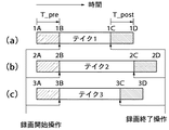
図3は、図2に示す処理により録画された異なる3つのテイクにおける録画のタイミングを示す図である。
【0044】
テイク1を記録する図3(a)では、タイミング1Bで録画開始操作が行われ、タイミング1Cで録画終了操作が行われている。タイミング1BからT_pre時間だけ前のタイミング1Aから、タイミング1CからT_post時間だけ後のタイミング1Dまでの圧縮本動画像がハードディスク109に記録される。このときに、タイミング1Bとタイミング1Cとがハードディスク109に記録される。
【0045】
テイク2,3をそれぞれ記録する図3(b)、(c)でも、図3(a)と同様な録画が行われる。
【0046】
このようにテイク1、2、3が順番に記録されると、それと平行して、CPU111が、ハードディスク109上に図4に示すようなプレイリスト1を生成して記録する。
【0047】
図4は、ハードディスク109上に記録されたプレイリスト1を示す図である。すなわちプレイリストは、記録された各テイクを再生する際の再生タイミング(ハードディスク109上の位置に相当)を示すものであり、最初にテイク1をタイミング1Bからタイミング1Cまでの期間(メモリ区間)で再生し、次にテイク2をタイミング2Bからタイミング2Cまでの期間で再生し、最後にテイク3をタイミング3Bからタイミング3Cまでの期間で再生して終了することを意味している。
【0048】
次に、デジタル動画像カメラが再生モードに設定されている場合の制御動作の説明を行なう。ここでは、シーンチェンジエフェクトが掛けられていない場合をまず説明する。
【0049】
デジタル動画像カメラは再生モードに設定されると、ハードディスク109上のプレイリストを解析して、その内容に従って再生を行なう。プレイリスト1には、上記の例ではまず“テイク1をタイミング1Bからタイミング1Cまで再生“と書かれているので、ハードディスク109からテイク1を探し出す。そしてタイミング(メモリ位置)1Bからテイク1の圧縮本動画像データを読み始める。その圧縮本動画像データは、動画圧縮解凍回路108にて解凍デコードされ、ディスプレイ106へ送られて再生される。読み出されるテイク1の圧縮本動画像データが、タイミング(メモリ位置)1Cに達したら、テイク1の再生をやめる。
【0050】
プレイリスト1には次に、”テイク2をタイミング2Bからタイミング2Cまで再生“と書かれているので、タイミング(メモリ位置)2Bからテイク2の圧縮本動画像データを読み始め、同様に動画圧縮解凍回路108へ送ることでデコードをおこない、ディスプレイ106で再生画を表示する。読み出されるテイク2の圧縮本動画像データが、タイミング(メモリ位置)2Cに達したら、テイク2の再生をやめる。そして、プレイリスト1には次に、”テイク3をタイミング3Bからタイミング3Cまで再生“と書かれているので、テイク3について、上記と同様な再生を行う。
【0051】
プレイリスト1ではテイク3の再生で終了となっているので、タイミング3Cに達したらプレイリスト1に従った再生を終了する。
【0052】
以上の再生動作では、プレイリストの解釈と再生動作とが平行して行われるが、プレイリストの解釈に時間がかかって再生動作が間に合わなくなる可能性がある場合には、これに代わって、まずプレイリストの解釈を先行して行い、その後に各テイクの再生を行うようにしてもよい。
【0053】
次に、シーンチェンジエフェクトが掛けられている場合の再生モードにおけるデジタル動画像カメラの制御動作の説明を行なう。
【0054】
図5は、シーンチェンジエフェクトが掛けられている場合の本発明におけるテイクの再生方法を示す図である。
【0055】
図5(a)、(b)に示すようにテイク1及びテイク2が記録されている場合において、再生時に、テイク1とテイク2との間にクロスフェードを実現するものとする。その場合、図5(c)に示すように、まずタイミング4Aからタイミング4Bまでの期間の映像として、テイク1のタイミング1Bからタイミング1Cまでの映像を再生する。
【0056】
次に、タイミング4Bからタイミング4Cまでの期間の映像としては、テイク1のタイミング1Cからタイミング1Dまでの期間の映像(後続画像信号)を、タイミング1Cから所定時間T_effectかけて少しづつにフェードアウトした映像と、テイク2のタイミング2Aからタイミング2Bまでの期間の映像(先行画像信号)を、タイミング2Bより所定時間T_effectだけ前のタイミングから少しずつフェードインした映像とをミックスした映像を生成する。
【0057】
次に、タイミング4Cからタイミング4Dまでの期間の映像としては、テイク2のタイミング2Bからタイミング2Cまでの期間の映像を再生する。
【0058】
こうした本発明におけるクロスフェードによれば、テイク1及びテイク2における録画開始操作時点(1B,2B)から録画終了操作時点(1C,2C)までの期間の各映像は、フェードインまたはフェードアウトされることがないので、完全な映像が再生されることになる。
【0059】
なおここでは、シーンチェンジエフェクトの代表例としてのクロスフェードをテイク間に掛けることを説明したが、本発明は各種シーンチェンジエフェクトに適用可能である。すなわち、様々な形態のワイプ、スピン、スイング、ページがめくれるようなエフェクト等、動画から動画へのシーンチェンジエフェクトはいろいろ存在するが、いずれのシーンチェンジエフェクトにおいても、本発明は実現できる。
【0060】
次に、撮影記録時における動作状態のディスプレイ106への表示について説明する。
【0061】
図6は、1テイク分を撮影記録する際にディスプレイ106に表示される各種の撮影記録状態を経過時間に沿って示す図である。
【0062】
記録開始操作時点よりも前の先行撮影記録状態をモード1、記録開始操作時点から記録終了操作時点までの撮影記録状態をモード2、記録終了操作時点から後の後続撮影記録状態をモード3とした場合、モード1では、記録待機を表す“pause”をディスプレイ106に表示する。これは、実際には先行撮影記録が行われているものの、デジタル動画像カメラとしては記録待機状態であるので、こうした表示を行うようにする。次にモード2では、本来の撮影記録状態となるので、記録を表す“rec”の表示を行なう。そしてモード3では、のりしろ記録(所定時間T_postに亘る撮影記録)をしている旨の表示として、“rec”の点滅表示を行なう。すなわちモード3では、記録終了操作後ののりしろ記録が行われることになるが、ここでは、カメラを被写体に向けた構えをユーザに継続させるために、“rec”の点滅表示を行なう。
【0063】
図7は、ディスプレイ106上の3つのモード表示例を示す図である。
【0064】
なお、これらの表示を、上記の例では“pause”、“rec”、「“rec”の点滅」としたが、 これに代わって“一時停止”、 “録画”、「“録画”の点滅」とするようにしてもよい。あるいは、それらの状態を示すアイコンによって表示するようにしてもよい。
【0065】
なおまた、図1における動画圧縮解凍回路108は、モーションJPEGのような、1枚1枚のコマを独立して圧縮符号化する動画符号化方式を実行する回路にしてもよいし、またMPEGのような、コマに応じて、独立して圧縮符号化したり、前後のコマの差分をとって圧縮符号化したり、また、複数のコマから予測して圧縮符号化したりする動画符号化方式を実行する回路にしてもよい。また、ハードディスク109は、光ディスクや光磁気ディスク等のディスクメディアでもよいし、FLASHメモリやSRAM,DRAM等の固体半導体メモリで構成されるランダムアクセス可能なメモリであってもよい。
【0066】
さらになお、前述した実施の形態の機能を実現するソフトウェアのプログラムコードを記憶した記憶媒体を、システムあるいは装置に供給し、そのシステムあるいは装置のコンピュータ(またはCPUやMPU)が記憶媒体に格納されたプログラムコードを読み出して実行することによっても、本発明が達成されることは言うまでもない。
【0067】
この場合、記憶媒体から読み出されたプログラムコード自体が、前述の実施の形態の機能を実現することになり、そのプログラムコードを記憶した記憶媒体が本発明を構成することになる。
【0068】
プログラムコードを供給するための記憶媒体として、例えば、フロッピィディスク、ハードディスク、光ディスク、光磁気ディスク、CD−ROM、CD−R、磁気テープ、不揮発性のメモリカード、ROMなどを用いることができる。
【0069】
また、コンピュータが読み出したプログラムコードを実行することにより、前述した実施の形態の機能が実現されるだけでなく、そのプログラムコードの指示に基づき、コンピュータ上で稼働しているOSなどが実際の処理の一部または全部を行い、その処理によって前述した実施の形態の機能が実現される場合も、本発明に含まれることは言うまでもない。
【0070】
さらに、記憶媒体から読み出されたプログラムコードが、コンピュータに挿入された機能拡張ボードやコンピュータに接続された機能拡張ユニットに備わるメモリに書き込まれた後、そのプログラムコードの指示に基づき、その機能拡張ボードや機能拡張ユニットに備わるCPUなどが実際の処理の一部または全部を行い、その処理によって前述した実施の形態の機能が実現される場合も、本発明に含まれることは言うまでもない。
【0071】
【発明の効果】
以上詳述したように、本発明によれば、クロスフェード等のシーンチェンジエフェクトを掛けた場合でも、録画開始操作時点から録画終了操作時点までの期間に記録された映像を不鮮明になることなく再生することができる。
【図面の簡単な説明】
【図1】本発明に係るデジタル動画像カメラの一実施の形態の構成を示すブロック図である。
【図2】1テイク分の動画像を撮影する際にCPUで行われる処理の手順を示すフローチャートである。
【図3】図2に示す処理により録画された異なる3つのテイクにおける録画のタイミングを示す図である。
【図4】ハードディスク上に記録されたプレイリストを示す図である。
【図5】シーンチェンジエフェクトが掛けられている場合の本発明におけるテイクの再生方法を示す図である。
【図6】1テイク分を撮影記録する際にディスプレイに表示される各種の撮影記録状態を経過時間に沿って示す図である。
【図7】ディスプレイ上の3つのモード表示例を示す図である。
【図8】従来の磁気テープにおけるシーケンシャル記録方式を示す図である。
【図9】従来のランダムアクセスメディアに記録された“テイク1”及び“テイク2”を示す図である。
【符号の説明】
101 レンズ
102 撮像素子
103 カメラ信号処理部
104 画像メモリ
105 操作スイッチ
106 ディスプレイ
107 画像処理部
108 動画圧縮解凍回路
109 ハードディスク
110 インターフェース
111 CPU
112 プログラムメモリ
113 プログラムフラッシュメモリ[0001]
BACKGROUND OF THE INVENTION
The present inventionRecording apparatus and methodIn particular, a moving image is taken and recorded on a recording medium.Recording apparatus and methodAbout.
[0002]
[Prior art]
2. Description of the Related Art Conventionally, there is a digital VTR (Video Tape Recorder) that records a moving image and records the image on a magnetic tape after the image signal is converted into a digital signal. Since the recording medium is a magnetic tape, this digital VTR is a sequential recording method in which video takes (time-continuous video information obtained from the start to the end of the shooting and recording operation) are sequentially recorded in the shooting order. Is common. This will be described with reference to FIG.
[0003]
FIG. 8 is a diagram showing a sequential recording method in a conventional magnetic tape.
[0004]
As shown in FIG. 8A, the recording of “take 1” is started together with the recording start operation of the digital VTR. Recording of “take 1” is ended by the operation of ending recording. Subsequently, when a recording start operation is performed, recording of “take 2” is started after “take 1”. Thereafter, the recording of “Take 2” is completed by the operation of ending recording. Thereafter, “take 3” is recorded following “take 2” by the same operation.
[0005]
When playing back images recorded by the sequential recording method, the order of the takes to be played is the same as that of recording, and it is difficult to find a desired scene or change the order.
[0006]
On the other hand, a random access memory video to be recorded on a solid disk or magneto-optical disk, which is a medium that can be randomly accessed, or a solid memory such as a flash memory or SRAM has been proposed. In the video recorded in the random access memory, the take is randomly recorded in an empty area of the memory. This will be described with reference to FIG.
[0007]
FIG. 9 is a diagram illustrating “take 1” and “take 2” recorded on a conventional random access medium.
[0008]
As shown in FIGS. 9A and 9B, the take recording is started by the recording start operation and the take recording is ended by the recording end operation. However, “take 1” and “take 2” Are recorded on the medium independently of each other. In this method, due to the nature of the media, the reading order does not depend on the recording order and can be arbitrarily read from any recording location. For this reason, it is possible to easily find and play a favorite moving image scene or to interchange the order of a plurality of scenes.
[0009]
By the way, in these digital video recording systems, the input digital signal is subjected to compression processing in order to reduce the amount of information, and it becomes possible to record a large amount of image information and still image information with a small storage capacity. Yes. There are various compression methods for such an image recording / reproducing apparatus.
[0010]
For example, in the orthogonal transform method, an image is divided into blocks each composed of n pixels × n pixels, orthogonal transform such as discrete cosine transform (DCT) is performed for each block, and each obtained coefficient is rounded to a predetermined number of bits. Quantize. In general, since image information is biased toward a low frequency region, the amount of data can be reduced by reducing the number of bits of high frequency components. Also, in a variable length coding method such as Huffman coding, efficient data compression can be performed by assigning a code having a shorter length to a bit sequence having a higher appearance probability.
[0011]
Further, when a moving image is compressed, the amount of data is greatly reduced by extracting a difference between frames by utilizing the property that a moving image has a strong correlation between image frames.
[0012]
The video data can be compressed by combining the above-mentioned various compression technologies to reduce the amount of data, and then recorded on a tape as a sequential access medium, a solid magnetic disk memory or an optical disk memory as a random access medium, etc. This is generally performed in a moving image recording system.
[0013]
By the way, in these moving image recording systems, it has been conventionally performed to apply a scene change effect such as a cross fade to a connecting portion between takes.
[0014]
In a digital VTR or the like using sequential access media, it is necessary to apply a scene change effect such as crossfading at the time of recording, and this procedure will be described with reference to FIG. That is, when the recording start operation starts recording “Take 1”, the recording end operation ends recording “Take 1”, and then starts recording the next “Take 2”. Take the scene as a still image. A crossfade is applied to this still image so that the beginning of “Take 2” appears little by little, and at the same time, the still image of the last scene in Take 1 disappears little by little. It is assumed that the image is only a 2 ″ moving image. At the end of recording, the recording of “Take 2” ends.
[0015]
In this case, because of the nature of sequential access media, it is not possible to simultaneously read two movies of “Take 1” and “Take 2”, or to record “Take 2” while reading “Take 1”. As long as each take is continuously recorded on this tape, a cross-fade from a moving image to a moving image is impossible, and only a cross-fade from a still image to a moving image can be realized. Further, since it is necessary to apply a crossfade at the same time during recording, an operation for applying a crossfade is required during shooting, which complicates the operation and has a drawback that the user cannot concentrate on shooting.
[0016]
On the other hand, when a scene change effect such as crossfading is applied to a take recorded on a random access medium, the above-described drawbacks in the case of using a sequential access medium are eliminated. Hereinafter, a case where a scene change effect such as a cross fade is applied to the connecting portion of “take 1” and “take 2” recorded on the random access medium will be described.
[0017]
In the case of random access media, a scene change effect such as a crossfade can be applied between takes during recording, but a scene change effect such as a crossfade can be applied between takes during playback rather than during recording. This will be described with reference to FIG.
[0018]
As shown in FIG. 9 (c), “Take 1” that has been shot is played back, and the last part of Take 1 to be crossfade disappears little by little, and at the same time, the beginning of “Take 2” Crossfade so that appears gradually, and finally only the “Take 2” video. Since it is a random access medium, take 1 and take 2 can be played back simultaneously, and in the crossfade part, the cross-fade from video to video is realized by changing the mix ratio of these two videos little by little. It is possible.
[0019]
[Problems to be solved by the invention]
By the way, in general, the video of a take is an image obtained by the user intentionally starting recording by the recording start operation and the user intentionally ending recording by the recording end operation. Is likely to be included.
[0020]
Nevertheless, if a crossfade scene change effect is applied at the time of transition from “Take 1” to “Take 2” recorded on the random access medium, for example, the end of “Take 1” If an important video is included in the head portion of “Take 2”, the important video becomes unclear due to fade-out or fade-in, and cannot be clearly seen.
[0021]
The present invention has been made in view of such problems, and even when a scene change effect such as crossfading is applied, the video recorded in the period from the recording start operation time to the recording end operation time is unclear. To be played without becomingRecording apparatus and methodThe purpose is to provide.
[0022]
[Means for Solving the Problems]
In order to achieve the above object, the recording apparatus of the present invention comprises:ShootImage means, recording means for recording the moving image signal output from the imaging means on a recording medium, instruction means for instructing recording start and recording end of the moving image signal,The recording is started so that recording of a moving image signal to the recording medium is started in response to an instruction to start recording by the instruction means, and recording of the moving image signal to the recording medium is ended in response to an instruction to end recording by the instruction means. And a moving image signal output from the imaging means between the first predetermined period before the recording start instruction and the second predetermined period after the recording end instruction as one take. In the moving image signal of one take recorded on the recording medium in response to the recording of the moving image signal of one take by the recording means, the control means for controlling the recording means to record From the position where recording is instructed to the position where recording is instructedAnd generating means for generating playlist data for controlling a reproduction procedure of a moving image signal recorded on the recording medium for reproduction.
To achieve the above object, the recording apparatus of the present invention comprises a recording means for recording an input moving image signal on a recording medium, an instruction means for instructing recording start and recording end of the moving image signal, and the instruction The recording means is configured to start recording a moving image signal on the recording medium in response to an instruction to start recording by the means, and end recording of the moving image signal to the recording medium in response to an instruction to end recording from the instruction means. Control means for controlling the recording means to record a take of a moving image including a moving image signal input between the recording start instruction and the recording end instruction, and the one take is the When recorded on a recording medium, a moving image signal from the position where the start of recording is instructed to the position where the end of recording is instructed in one take is reproduced, and the one take is included. Generate playlist data for controlling the playback procedure of the video signals of the multiple takes recorded on the recording medium so that the video signals of the multiple takes are continuously played back in the order recorded on the recording medium And generating means.
In order to achieve the above object, a recording apparatus control method according to the present invention is a recording apparatus control method for recording a moving image signal output from an imaging means on a recording medium, wherein a recording start instruction is given by an instruction means. In response to this, the recording of the moving image signal to the recording medium is started, the recording of the moving image signal to the recording medium is ended in response to the recording end instruction by the instruction means, and a first predetermined period from the recording start instruction A control step for controlling the recording apparatus so as to record the moving image signal output from the imaging means as one take from before the recording end instruction to after a second predetermined period, and one take In response to the recording of the moving image signal, the recording end is instructed from the position where the recording start is instructed in the moving image signal of the one take recorded on the recording medium. Until the position, characterized in that it comprises a generation step of generating a play list data for controlling the reproduction procedure of the recorded moving picture signal on the recording medium to play.
In order to achieve the above object, a control method for a recording apparatus according to the present invention is a control method for a recording apparatus that records an input moving image signal on a recording medium. Recording of the moving image signal to the recording medium is started, and recording of the moving image signal to the recording medium is ended according to the recording end instruction by the instruction unit, and between the recording start instruction and the recording end instruction. A control step for controlling the recording device to record a take of a moving image including an input moving image signal; and when one take is recorded on the recording medium, the start of recording is instructed in the one take The moving image signal from the recorded position to the position where the end of recording is instructed is reproduced, and the moving image signals of a plurality of takes including the one take are recorded in the order recorded on the recording medium. Characterized in that it comprises a generation step of generating a play list data for controlling the reproduction procedure of the recorded multiple takes of a moving picture signal on the recording medium so as to reproduce continue to.
[0025]
DETAILED DESCRIPTION OF THE INVENTION
Hereinafter, embodiments of the present invention will be described with reference to the drawings.
[0026]
FIG. 1 is a block diagram showing the configuration of an embodiment of a digital video camera according to the present invention. Note that, in moving image shooting, a series of moving image scenes obtained from when the shooting button is pressed to start shooting and when the shooting button is pressed again to end shooting is referred to as one take.
[0027]
A compressed program is stored in the
[0028]
First, the control operation when the digital video camera is set to the recording mode will be described.
[0029]
Light from the subject is imaged on the
[0030]
By the way, regardless of the shooting start operation by the user, the moving image compression /
[0031]
When shooting is started by a user pressing a shooting button (not shown) included in the operation switch 105 (shooting start operation), a certain amount of time before the shooting start time stored in the
[0032]
Next, when the shooting button included in the
[0033]
At this time, the time when the shooting button included in the
[0034]
FIG. 2 is a flowchart showing a procedure of processing performed by the
[0035]
When the recording mode is entered, execution of the processing is started (S201).
[0036]
First, in step S202, a compressed main moving image (preceding image signal) for a predetermined time (T_pre) from the present to the past is always held in the
[0037]
Next, in step S203, it is determined whether or not a shooting button included in the
[0038]
In step S204, the compressed main moving image (preceding image signal) for a predetermined time (T_pre) held in the
[0039]
In step S206, it is determined whether or not the shooting button included in the
[0040]
In step S207, shooting is continued until a predetermined time (T_post) elapses from the time when the recording end operation is performed. Then, a compressed main moving image (subsequent image signal) for a predetermined time (T_post) is recorded on the
[0041]
Next, in step S208, the time when the recording start operation is performed and the time when the recording end operation is performed are recorded on the
[0042]
In step S208, the recording start operation time and the recording end operation time are stored in the
[0043]
FIG. 3 is a diagram showing recording timings in three different takes recorded by the process shown in FIG.
[0044]
In FIG. 3A in which take 1 is recorded, a recording start operation is performed at
[0045]
Recordings similar to FIG. 3A are also performed in FIGS. 3B and 3C in which the takes 2 and 3 are recorded, respectively.
[0046]
When takes 1, 2, and 3 are recorded in order, the
[0047]
FIG. 4 is a diagram showing the playlist 1 recorded on the
[0048]
Next, the control operation when the digital moving image camera is set to the playback mode will be described. Here, the case where the scene change effect is not applied will be described first.
[0049]
When the digital video camera is set to the playback mode, the playlist on the
[0050]
Next, since “Playback Take 2 from
[0051]
Since the play list 1 is finished with the reproduction of the
[0052]
In the above playback operation, the interpretation of the playlist and the playback operation are performed in parallel.If there is a possibility that the playback operation may not be in time due to the time taken to interpret the playlist, The play list may be interpreted in advance, and then each take may be reproduced.
[0053]
Next, the control operation of the digital video camera in the playback mode when the scene change effect is applied will be described.
[0054]
FIG. 5 is a diagram showing a take reproduction method according to the present invention when a scene change effect is applied.
[0055]
When take 1 and take 2 are recorded as shown in FIGS. 5A and 5B, a cross fade is realized between take 1 and take 2 during reproduction. In that case, as shown in FIG. 5C, first, the video from the
[0056]
Next, as a video from the
[0057]
Next, as the video from the timing 4C to the
[0058]
According to the cross fade in the present invention, each video in the period from the recording start operation time (1B, 2B) to the recording end operation time (1C, 2C) in take 1 and take 2 is faded in or faded out. Since there is no video, the complete video is played.
[0059]
In addition, although the cross fade as a typical example of the scene change effect is described here between the takes, the present invention can be applied to various scene change effects. That is, there are various scene change effects from moving images to moving images, such as various types of wipes, spins, swings, and page turning effects, but the present invention can be realized with any scene change effect.
[0060]
Next, the display on the
[0061]
FIG. 6 is a diagram showing various shooting and recording states displayed on the
[0062]
The preceding shooting recording state before the recording start operation time is mode 1, the shooting recording state from the recording start operation time to the recording end operation time is mode 2, and the subsequent shooting recording state after the recording end operation time is
[0063]
FIG. 7 is a diagram showing three mode display examples on the
[0064]
These displays are “pause”, “rec”, “flashing“ rec ”” in the above example, but “pause”, “recording”, “flashing“ recording ”instead. You may make it. Or you may make it display with the icon which shows those states.
[0065]
In addition, the moving image compression /
[0066]
Furthermore, a storage medium storing software program codes for realizing the functions of the above-described embodiments is supplied to the system or apparatus, and the computer (or CPU or MPU) of the system or apparatus is stored in the storage medium. It goes without saying that the present invention can also be achieved by reading and executing the program code.
[0067]
In this case, the program code itself read from the storage medium realizes the functions of the above-described embodiment, and the storage medium storing the program code constitutes the present invention.
[0068]
As a storage medium for supplying the program code, for example, a floppy disk, hard disk, optical disk, magneto-optical disk, CD-ROM, CD-R, magnetic tape, nonvolatile memory card, ROM, or the like can be used.
[0069]
Further, by executing the program code read by the computer, not only the functions of the above-described embodiments are realized, but also the OS running on the computer based on the instruction of the program code performs actual processing. Needless to say, the present invention also includes a case where the functions of the above-described embodiment are realized by performing part or all of the above-described processing.
[0070]
Further, after the program code read from the storage medium is written to a memory provided in a function expansion board inserted into the computer or a function expansion unit connected to the computer, the function expansion is performed based on the instruction of the program code. Needless to say, the present invention includes the case where the CPU or the like provided in the board or the function expansion unit performs part or all of the actual processing and the functions of the above-described embodiments are realized by the processing.
[0071]
【The invention's effect】
As detailed above,According to the present invention, even when a scene change effect such as crossfading is applied, a video recorded in a period from the recording start operation time to the recording end operation time can be reproduced without being blurred..
[Brief description of the drawings]
FIG. 1 is a block diagram showing a configuration of an embodiment of a digital moving image camera according to the present invention.
FIG. 2 is a flowchart illustrating a procedure of processing performed by a CPU when a moving image for one take is captured.
FIG. 3 is a diagram showing recording timings in three different takes recorded by the process shown in FIG. 2;
FIG. 4 is a diagram showing a playlist recorded on a hard disk.
FIG. 5 is a diagram illustrating a take reproduction method according to the present invention when a scene change effect is applied;
FIG. 6 is a diagram showing various shooting / recording states displayed on a display when shooting and recording one take along the elapsed time.
FIG. 7 is a diagram showing three mode display examples on the display.
FIG. 8 is a diagram showing a sequential recording method in a conventional magnetic tape.
FIG. 9 is a diagram showing “take 1” and “take 2” recorded on a conventional random access medium;
[Explanation of symbols]
101 RenThe
102 Imaging elementChild
103 Camera signal processingPart
104 Image memoRe
105 Operation switch
106 display
107 Image processing unit
108 Video compression / decompression circuit
109 HarddisThe
110 interface
111CPU
112 Program memory
113 Program flash memory
Claims (8)
前記撮像手段から出力された動画像信号を記録媒体に記録する記録手段と、
前記動画像信号の記録開始と記録終了を指示する指示手段と、
前記指示手段による記録開始の指示に応じて前記記録媒体に対する動画像信号の記録を開始し前記指示手段による記録終了の指示に応じて前記記録媒体に対する動画像信号の記録を終了するように前記記録手段を制御すると共に、前記記録開始の指示より第1の所定期間前から前記記録終了の指示より第2の所定期間後までの間に前記撮像手段から出力された動画像信号を一つのテイクとして記録するよう前記記録手段を制御する制御手段と、
前記記録手段により一つのテイクの動画像信号が記録されたことに応じて、前記記録媒体に記録された前記一つのテイクの動画像信号において前記記録開始が指示された位置から記録終了が指示された位置までを再生するよう前記記録媒体に記録された動画像信号の再生手順を制御するためのプレイリストデータを生成する生成手段とを備えることを特徴とする記録装置。And an imaging means,
Recording means for recording the moving image signal output from the imaging means on a recording medium;
Instruction means for instructing recording start and recording end of the moving image signal;
The recording is started so that recording of a moving image signal to the recording medium is started in response to an instruction to start recording by the instruction means, and recording of the moving image signal to the recording medium is ended in response to an instruction to end recording by the instruction means. And a moving image signal output from the imaging means between the first predetermined period before the recording start instruction and the second predetermined period after the recording end instruction as one take. Control means for controlling the recording means to record;
In response to the recording of the moving image signal of one take by the recording means, the recording end is instructed from the position where the recording start is instructed in the moving image signal of the one take recorded on the recording medium. A recording apparatus comprising: generating means for generating playlist data for controlling a reproduction procedure of a moving image signal recorded on the recording medium so as to reproduce up to a predetermined position .
前記生成手段は、前記記録手段により一つのテイクの動画像信号が記録されたことに応じて、前記一つのテイクのうち前記本動画像信号の先頭から最後までを再生するよう前記記録媒体に記録された動画像信号の再生手順を制御するためのプレイリストデータを生成することを特徴とする請求項1記載の記録装置。The control means includes a pre-action image signal output from the imaging means between a first predetermined period before the recording start instruction and the recording start instruction, and the recording end instruction from the recording end instruction. A subsequent moving image signal output from the imaging unit between a second predetermined period after the instruction and a main moving image signal output from the imaging unit between the recording start instruction and the recording end instruction. , Controlling the recording means to record as the one take,
Said generating means, said moving image signal recording means by Ri one to take in response to is recorded, the one of the one-take to play from the beginning of the moving image signal to the end the recording medium 2. The recording apparatus according to claim 1, wherein playlist data for controlling a reproduction procedure of the moving image signal recorded on the recording medium is generated.
前記再生手段は、前記記録媒体から連続して二つの前記テイクを再生する場合に、前記二つのテイクのうち先に再生されるテイクの後続動画像信号と後に再生されるテイクの先行動画像信号と用いてエフェクト画像信号を生成することを特徴とする請求項2記載の記録装置。Reproducing means for reproducing a plurality of the moving image signals of the take recorded on the recording medium,
The reproducing means, when reproducing the two takes from the recording medium in succession, the subsequent moving image signal of the take to be reproduced first of the two takes and the preceding action image signal of the take to be reproduced later The recording apparatus according to claim 2, wherein an effect image signal is generated.
前記記録手段は前記記録開始の指示の時点で前記メモリに記憶されている前記第1の所定期間分の動画像信号を前記記録開始の指示に応じて読み出し、前記記録媒体に記録することを特徴とする請求項1乃至4の何れか1項に記載の記録装置。A memory capable of storing moving image signals for the first predetermined period and storing the moving image signals output from the imaging means;
The recording means reads out the moving image signals for the first predetermined period stored in the memory at the time of the instruction to start recording in accordance with the instruction to start recording, and records them on the recording medium. The recording apparatus according to any one of claims 1 to 4 .
前記動画像信号の記録開始と記録終了を指示する指示手段と、
前記指示手段による記録開始の指示に応じて前記記録媒体に対する動画像信号の記録を開始し前記指示手段による記録終了の指示に応じて前記記録媒体に対する動画像信号の記録を終了するように前記記録手段を制御すると共に、前記記録開始の指示から記録終了の指示までの間に入力された動画像信号を含む動画像のテイクを記録するよう前記記録手段を制御する制御手段と、
一つの前記テイクが前記記録媒体に記録されると、前記一つのテイクにおいて前記記録開始が指示された位置から記録終了が指示された位置までの動画像信号を再生し、前記一つのテイクを含む複数のテイクの動画像信号を前記記録媒体に記録された順番で連続して再生するよう前記記録媒体に記録された複数のテイクの動画像信号の再生手順を制御するためのプレイリストデータを生成する生成手段とを備えることを特徴とする記録装置。Recording means for recording the input moving image signal on a recording medium;
Instruction means for instructing recording start and recording end of the moving image signal;
The recording is started such that recording of a moving image signal to the recording medium is started in response to an instruction to start recording by the instruction means, and recording of the moving image signal to the recording medium is ended in response to an instruction to end recording by the instruction means. And a control means for controlling the recording means to record a moving image take including a moving image signal input between the recording start instruction and the recording end instruction.
When one take is recorded on the recording medium, a moving image signal from the position where the start of recording is instructed to the position where the end of recording is instructed in the one take is reproduced, and includes the one take Generate playlist data for controlling the playback procedure of the video signals of a plurality of takes recorded on the recording medium so as to continuously play back the video signals of the plurality of takes in the order recorded on the recording medium And a generating unit.
指示手段による記録開始の指示に応じて前記記録媒体に対する動画像信号の記録を開始し前記指示手段による記録終了の指示に応じて前記記録媒体に対する動画像信号の記録を終了すると共に、前記記録開始の指示より第1の所定期間前から前記記録終了の指示より第2の所定期間後までの間に前記撮像手段から出力された動画像信号を一つのテイクとして記録するように前記記録装置を制御する制御ステップと、
一つのテイクの動画像信号が記録されたことに応じて、前記記録媒体に記録された前記一つのテイクの動画像信号において前記記録開始が指示された位置から記録終了が指示された位置までを再生するよう前記記録媒体に記録された動画像信号の再生手順を制御するためのプレイリストデータを生成する生成ステップとを備えることを特徴とする記録装置の制御方法。 A control method of a recording apparatus for recording a moving image signal output from an imaging means on a recording medium,
Recording of a moving image signal to the recording medium is started in response to an instruction to start recording by the instruction unit, recording of the moving image signal to the recording medium is ended in response to an instruction to end recording by the instruction unit, and The recording apparatus is controlled so that the moving image signal output from the imaging means is recorded as one take before the first predetermined period from the instruction to the second predetermined period after the recording end instruction. A control step to
In response to the recording of the moving image signal of one take, from the position instructed to start recording to the position instructed to end recording in the moving image signal of one take recorded on the recording medium. control method for a recording apparatus, characterized in that it comprises a generation step of generating a play list data for controlling the playback sequence of the recorded moving picture signal on the recording medium to play.
指示手段による記録開始の指示に応じて前記記録媒体に対する動画像信号の記録を開始し前記指示手段による記録終了の指示に応じて前記記録媒体に対する動画像信号の記録を終了すると共に、前記記録開始の指示から記録終了の指示までの間に入力された動画像信号を含む動画像のテイクを記録するよう前記記録装置を制御する制御ステップと、
一つの前記テイクが前記記録媒体に記録されると、前記一つのテイクにおいて前記記録開始が指示された位置から記録終了が指示された位置までの動画像信号を再生し、前記一つのテイクを含む複数のテイクの動画像信号を前記記録媒体に記録された順番で連続して再生するよう前記記録媒体に記録された複数のテイクの動画像信号の再生手順を制御するためのプレイリストデータを生成する生成ステップとを備えることを特徴とする記録装置の制御方法。A method of controlling a recording apparatus for recording an input moving image signal on a recording medium ,
Recording of a moving image signal to the recording medium is started in response to an instruction to start recording by the instruction unit, recording of the moving image signal to the recording medium is ended in response to an instruction to end recording by the instruction unit, and the recording is started A control step of controlling the recording device to record a take of a moving image including a moving image signal input between the instruction of the recording and the instruction to end recording;
When one of the take is recorded on the recording medium, and plays back the video signal from the recording start is instructed position in the one-take until the recording end is instructed position, including the one-take Generate playlist data for controlling the playback procedure of the video signals of a plurality of takes recorded on the recording medium so as to continuously play back the video signals of the plurality of takes in the order recorded on the recording medium And a generating step for controlling the recording apparatus.
Priority Applications (2)
| Application Number | Priority Date | Filing Date | Title |
|---|---|---|---|
| JP2001025801A JP4478343B2 (en) | 2001-02-01 | 2001-02-01 | Recording apparatus and method |
| US10/058,432 US7084908B2 (en) | 2001-02-01 | 2002-01-28 | Image signal recording apparatus with controlled recording of main, preceding and succeeding moving image signals |
Applications Claiming Priority (1)
| Application Number | Priority Date | Filing Date | Title |
|---|---|---|---|
| JP2001025801A JP4478343B2 (en) | 2001-02-01 | 2001-02-01 | Recording apparatus and method |
Publications (3)
| Publication Number | Publication Date |
|---|---|
| JP2002232834A JP2002232834A (en) | 2002-08-16 |
| JP2002232834A5 JP2002232834A5 (en) | 2008-03-13 |
| JP4478343B2 true JP4478343B2 (en) | 2010-06-09 |
Family
ID=18890726
Family Applications (1)
| Application Number | Title | Priority Date | Filing Date |
|---|---|---|---|
| JP2001025801A Expired - Fee Related JP4478343B2 (en) | 2001-02-01 | 2001-02-01 | Recording apparatus and method |
Country Status (2)
| Country | Link |
|---|---|
| US (1) | US7084908B2 (en) |
| JP (1) | JP4478343B2 (en) |
Families Citing this family (12)
| Publication number | Priority date | Publication date | Assignee | Title |
|---|---|---|---|---|
| JP3780252B2 (en) * | 2001-12-25 | 2006-05-31 | キヤノン株式会社 | Recording / reproducing apparatus and recording / reproducing method |
| JPWO2004021701A1 (en) | 2002-08-27 | 2005-12-22 | ソニー株式会社 | Data processing apparatus and method, and program |
| JP2005197785A (en) * | 2003-12-26 | 2005-07-21 | Canon Inc | Image pickup apparatus and image pickup method |
| JP4708733B2 (en) * | 2004-05-21 | 2011-06-22 | キヤノン株式会社 | Imaging device |
| JP4498159B2 (en) * | 2005-02-03 | 2010-07-07 | キヤノン株式会社 | Imaging apparatus and control method thereof |
| US20090041428A1 (en) * | 2007-08-07 | 2009-02-12 | Jacoby Keith A | Recording audio metadata for captured images |
| JP2009278465A (en) | 2008-05-15 | 2009-11-26 | Sony Corp | Recording control apparatus, recording control method, program, and, recording device |
| JP4600521B2 (en) * | 2008-06-03 | 2010-12-15 | ソニー株式会社 | Information processing apparatus, information processing method, and program |
| JP4596043B2 (en) * | 2008-06-03 | 2010-12-08 | ソニー株式会社 | Information processing apparatus, information processing method, and program |
| JP4596044B2 (en) * | 2008-06-03 | 2010-12-08 | ソニー株式会社 | Information processing system and information processing method |
| US8861926B2 (en) | 2011-05-02 | 2014-10-14 | Netflix, Inc. | Audio and video streaming for media effects |
| JP6418940B2 (en) * | 2014-12-25 | 2018-11-07 | キヤノン株式会社 | Electronic device and control method thereof |
Family Cites Families (6)
| Publication number | Priority date | Publication date | Assignee | Title |
|---|---|---|---|---|
| JPH11506574A (en) * | 1995-02-23 | 1999-06-08 | アヴィッド・テクノロジー・インコーポレーテッド | Combining editing and digital video recording systems |
| US6052508A (en) * | 1997-04-04 | 2000-04-18 | Avid Technology, Inc. | User interface for managing track assignment for portable digital moving picture recording and editing system |
| US6035367A (en) * | 1997-04-04 | 2000-03-07 | Avid Technology, Inc. | Computer file system providing looped file structure for post-occurrence data collection of asynchronous events |
| EP0920014A4 (en) * | 1997-04-12 | 2002-12-04 | Sony Corp | Editing device and editing method |
| US6163338A (en) * | 1997-12-11 | 2000-12-19 | Johnson; Dan | Apparatus and method for recapture of realtime events |
| EP0985899B1 (en) * | 1998-09-09 | 2004-02-04 | Mitsubishi Denki Kabushiki Kaisha | Video recording device for a targetable weapon |
-
2001
- 2001-02-01 JP JP2001025801A patent/JP4478343B2/en not_active Expired - Fee Related
-
2002
- 2002-01-28 US US10/058,432 patent/US7084908B2/en not_active Expired - Fee Related
Also Published As
| Publication number | Publication date |
|---|---|
| US7084908B2 (en) | 2006-08-01 |
| US20020101518A1 (en) | 2002-08-01 |
| JP2002232834A (en) | 2002-08-16 |
Similar Documents
| Publication | Publication Date | Title |
|---|---|---|
| JP2004048730A (en) | Method of displaying video stream | |
| JP4478343B2 (en) | Recording apparatus and method | |
| JP2001111963A (en) | Recording and reproducing method for video camera utilizing optical disk | |
| JPH07284058A (en) | Recording method | |
| JP3478515B2 (en) | Apparatus and method for recording and reproducing data | |
| US20080285949A1 (en) | Video motion menu generation in a low memory environment | |
| JP2002209190A (en) | Reproducing device, reproducing method, storage medium | |
| US7639920B2 (en) | Recorder | |
| KR100497913B1 (en) | Data recording apparatus, reproducing apparatus, recording/reproducing method, and imaging apparatus | |
| JP2005039792A (en) | Recording apparatus and reproducing apparatus | |
| KR100883119B1 (en) | Method for editing of moving picture file list | |
| JP2003023600A (en) | Image processor, animation recording/playback equipment, image processing method, program, and computer- readable storage medium | |
| JPH07264542A (en) | Moving image decoding device | |
| JP2000023081A (en) | Image reproducing device | |
| JP3104776B2 (en) | Image reproducing device and image decoding device | |
| US7742686B2 (en) | Signal processor | |
| JP3291392B2 (en) | Method and apparatus for reproducing compressed image data | |
| JP2002237973A (en) | Recorder, recording method and imaging device | |
| JP5968069B2 (en) | Image processing apparatus, imaging apparatus, image processing apparatus control method, and program | |
| JP2001211414A (en) | Image pick up device and recorder | |
| JP2007115308A (en) | Recording/reproducing device and recording/reproducing method | |
| JP2864950B2 (en) | Management method of compressed video data | |
| KR20080057142A (en) | Camera apparatus and still image generating method of camera apparatus | |
| JPH08214253A (en) | Disk device | |
| JP2006339995A (en) | Device, method, and program for reproduction, and storage medium |
Legal Events
| Date | Code | Title | Description |
|---|---|---|---|
| RD03 | Notification of appointment of power of attorney |
Free format text: JAPANESE INTERMEDIATE CODE: A7423 Effective date: 20060412 |
|
| RD05 | Notification of revocation of power of attorney |
Free format text: JAPANESE INTERMEDIATE CODE: A7425 Effective date: 20070626 |
|
| A521 | Request for written amendment filed |
Free format text: JAPANESE INTERMEDIATE CODE: A523 Effective date: 20080129 |
|
| A621 | Written request for application examination |
Free format text: JAPANESE INTERMEDIATE CODE: A621 Effective date: 20080129 |
|
| A977 | Report on retrieval |
Free format text: JAPANESE INTERMEDIATE CODE: A971007 Effective date: 20091201 |
|
| A131 | Notification of reasons for refusal |
Free format text: JAPANESE INTERMEDIATE CODE: A131 Effective date: 20091215 |
|
| A521 | Request for written amendment filed |
Free format text: JAPANESE INTERMEDIATE CODE: A523 Effective date: 20100215 |
|
| TRDD | Decision of grant or rejection written | ||
| A01 | Written decision to grant a patent or to grant a registration (utility model) |
Free format text: JAPANESE INTERMEDIATE CODE: A01 Effective date: 20100309 |
|
| A01 | Written decision to grant a patent or to grant a registration (utility model) |
Free format text: JAPANESE INTERMEDIATE CODE: A01 |
|
| A61 | First payment of annual fees (during grant procedure) |
Free format text: JAPANESE INTERMEDIATE CODE: A61 Effective date: 20100315 |
|
| R150 | Certificate of patent or registration of utility model |
Free format text: JAPANESE INTERMEDIATE CODE: R150 |
|
| FPAY | Renewal fee payment (event date is renewal date of database) |
Free format text: PAYMENT UNTIL: 20130319 Year of fee payment: 3 |
|
| FPAY | Renewal fee payment (event date is renewal date of database) |
Free format text: PAYMENT UNTIL: 20140319 Year of fee payment: 4 |
|
| LAPS | Cancellation because of no payment of annual fees |