JP4477909B2 - Glasses wearing simulation system and image generation method - Google Patents
Glasses wearing simulation system and image generation method Download PDFInfo
- Publication number
- JP4477909B2 JP4477909B2 JP2004079399A JP2004079399A JP4477909B2 JP 4477909 B2 JP4477909 B2 JP 4477909B2 JP 2004079399 A JP2004079399 A JP 2004079399A JP 2004079399 A JP2004079399 A JP 2004079399A JP 4477909 B2 JP4477909 B2 JP 4477909B2
- Authority
- JP
- Japan
- Prior art keywords
- image
- optical system
- simulation
- observation optical
- lens
- Prior art date
- Legal status (The legal status is an assumption and is not a legal conclusion. Google has not performed a legal analysis and makes no representation as to the accuracy of the status listed.)
- Expired - Lifetime
Links
- 238000004088 simulation Methods 0.000 title claims description 124
- 238000000034 method Methods 0.000 title claims description 55
- 239000011521 glass Substances 0.000 title claims description 8
- 230000003287 optical effect Effects 0.000 claims description 155
- 238000012545 processing Methods 0.000 claims description 59
- 230000006870 function Effects 0.000 claims description 21
- 230000004075 alteration Effects 0.000 claims description 7
- 238000001514 detection method Methods 0.000 claims description 7
- 230000000750 progressive effect Effects 0.000 claims description 7
- 230000004418 eye rotation Effects 0.000 claims description 2
- 238000013461 design Methods 0.000 description 16
- 210000001508 eye Anatomy 0.000 description 6
- 238000010586 diagram Methods 0.000 description 5
- 238000012360 testing method Methods 0.000 description 4
- 201000009310 astigmatism Diseases 0.000 description 2
- 239000000872 buffer Substances 0.000 description 2
- 238000012937 correction Methods 0.000 description 2
- 241000226585 Antennaria plantaginifolia Species 0.000 description 1
- 238000012935 Averaging Methods 0.000 description 1
- 210000005252 bulbus oculi Anatomy 0.000 description 1
- 239000003086 colorant Substances 0.000 description 1
- 238000011161 development Methods 0.000 description 1
- 238000005259 measurement Methods 0.000 description 1
- 201000010041 presbyopia Diseases 0.000 description 1
Images


Landscapes
- Eyeglasses (AREA)
- Eye Examination Apparatus (AREA)
Description
本発明は、被処方者に眼鏡レンズ装用時の状態を疑似体験させるためのシミュレーション画像処理装置、および該装置において被処方者に表示する画像を生成する画像生成方法に関する。 The present invention relates to a simulation image processing apparatus for causing a prescriber to experience a state of wearing a spectacle lens, and an image generation method for generating an image to be displayed to the prescriber in the apparatus.
近年、眼鏡処方におけるテーラーメイド医療を行うために必要かつ精確な情報を取得したり、またはインフォームドコンセントとして診療に必要な情報を被処方者に正しく提供したりすることが強く要望されている。該要望に応えるために、該被処方者が眼鏡を装用した場合にどのような見え方をするかを該被処方者にシミュレーション(疑似体験)させるための眼鏡装用シミュレーションシステムの開発が急がれている。なお、本願では、眼鏡装用シミュレーションシステムを用いて疑似体験をする被処方者を被験者という。 In recent years, there has been a strong demand to acquire necessary and accurate information necessary for performing tailor-made medical care in spectacle prescriptions, or to correctly provide information necessary for medical treatment as an informed consent to a prescriber. In order to meet this demand, the development of a simulation system for wearing spectacles to make the prescriber simulate (pseudo-experience) how the prescription will look when wearing spectacles is urgently required. ing. In addition, in this application, the prescription person who performs a pseudo experience using a spectacles wearing simulation system is called a test subject.
一般的に、眼鏡装用シミュレーションシステムでは、シミュレーション対象となる眼鏡レンズ(つまり、将来被験者が装用するであろう眼鏡レンズ。以下、説明の便宜上、仮想レンズという。)を装用したときに観察されるシミュレーション画像が作成される。被検者は、該シミュレーション画像を観察することにより、将来眼鏡をかけた時の像の見え方を疑似体験することができる。そのため、該映像は、仮想レンズの収差に起因して発生するボケが可能な限り忠実に再現される必要がある。特に、仮想レンズが累進屈折力レンズである場合には、像の歪みも忠実に再現される必要もある。つまり、眼鏡装用シミュレーションシステムを用いて、実使用時により近い高品質なシミュレーションを提供できるかどうかは、物体距離に対するボケの変化や、度数の変化に起因する像の歪みをいかに精確に表現できるかという課題に依存する。該課題を解決するためには、仮想レンズ各部位における物体距離の変化に応じた光学特性の変化を、高精度かつ短時間で求めることが必要不可欠である。上記のような仮想レンズによるボケや歪みを実現可能な眼鏡装用シミュレーションシステムとしては、従来、以下の文献に開示されるような構成が例示される。 Generally, in a spectacle wearing simulation system, a simulation observed when a spectacle lens to be simulated (that is, a spectacle lens that a subject will wear in the future; hereinafter referred to as a virtual lens for convenience of explanation) is worn. An image is created. By observing the simulation image, the subject can have a simulated experience of how the image will look when wearing glasses in the future. For this reason, the image needs to be reproduced as faithfully as possible from the blur caused by the aberration of the virtual lens. In particular, when the virtual lens is a progressive power lens, it is also necessary to faithfully reproduce image distortion. In other words, whether or not a spectacle wearing simulation system can provide a high-quality simulation that is closer to that in actual use can accurately represent the change in blur with respect to the object distance and the distortion of the image due to the change in power. It depends on the problem. In order to solve the problem, it is indispensable to obtain a change in optical characteristics according to a change in the object distance in each part of the virtual lens with high accuracy and in a short time. As a spectacle wearing simulation system capable of realizing blur and distortion due to the virtual lens as described above, configurations as disclosed in the following documents are conventionally exemplified.
上記各文献で例示される眼鏡装用シミュレーションシステムにおいて、一般に、被験者は、ヘッドマウントディスプレイ(以下、HMDという)やモニタといった画像表示部を介してシミュレーション画像を観察する。しかし、上記従来の装置で生成された画像は、仮想レンズに起因する像のボケや歪みしか有していない。そのため、例えば、HMDのように内部に光学系(観察光学系)を有するものを用いてシミュレーションを行う場合、被験者は、仮想レンズによる像歪みと観察光学系による像歪みとが融合された画像をシミュレーション画像として知覚してしまう。さらに、画像表示部における観察光学系の有無を問わず、被験者が既に眼鏡(眼鏡光学系)を装用している場合、被験者は自らが装用する眼鏡光学系による歪みも融合された画像をシミュレーション画像として知覚してしまう。 In the eyeglass wearing simulation system exemplified in each of the above documents, generally, a subject observes a simulation image via an image display unit such as a head mounted display (hereinafter referred to as HMD) or a monitor. However, the image generated by the conventional apparatus has only blurring and distortion of the image due to the virtual lens. Therefore, for example, when a simulation is performed using an optical system (observation optical system) such as an HMD, the test subject displays an image in which the image distortion caused by the virtual lens and the image distortion caused by the observation optical system are fused. Perceived as a simulation image. Furthermore, regardless of the presence or absence of the observation optical system in the image display unit, when the subject already wears spectacles (glasses optical system), the subject simulates an image in which distortion caused by the spectacle optical system worn by himself / herself is also fused. Perceived as.
従って、従来の眼鏡装用シミュレーションシステムでは、その使用状態や被験者の眼鏡装用の有無により、必ずしも精確なシミュレーションが実現されないといった問題点が残存していた。 Therefore, in the conventional spectacle wearing simulation system, there remains a problem that an accurate simulation is not necessarily realized depending on the usage state and the presence or absence of the spectacle wearing of the subject.
以上の事情に鑑みて、本発明は、被験者が上記の観察光学系や眼鏡光学系を介してシミュレーションを行う場合であっても、仮想レンズに起因する像のボケや歪みが精確に体験できるシミュレーション可能な眼鏡装用シミュレーションシステム、および被験者が仮想レンズ装用時に観察し得る像を精確に知覚できるような画像を生成する画像生成方法を提供することを目的とする。 In view of the above circumstances, the present invention is a simulation in which the subject can accurately experience blurring and distortion of an image caused by a virtual lens even when the subject performs a simulation through the observation optical system or the spectacle optical system. An object of the present invention is to provide a spectacle wearing simulation system that can be used, and an image generating method that generates an image that allows a subject to accurately perceive an image that can be observed when wearing a virtual lens.
上記の問題を鑑みて、本発明に係る眼鏡装用シミュレーションシステムは、仮想の眼鏡レンズを装用したときに観察し得る像を、画像表示装置を介して被験者に疑似体験させる眼鏡装用シミュレーションシステムにおいて、仮想レンズに関する複数のパラメータを入力する第一の入力手段と、仮想レンズに関する複数のパラメータに基づいて仮想レンズの光学データを生成する第一の光学データ生成手段と、観察光学系に関する複数のパラメータを入力する第二の入力手段と、観察光学系に関する複数のパラメータに基づいて上記像に対応するシミュレーション画像を観察するために用いられる観察光学系の光学データを生成する第二の光学データ生成手段と、仮想レンズの光学データおよび観察光学系の光学データに基づいて、原画像に、仮想レンズの持つ歪みを付与し、観察光学系の持つ歪みを打ち消すような画像処理を施してシミュレーション画像を生成する画像生成手段を有することを特徴とする。 In view of the above problems, spectacle wearing simulation system according to the present invention, an image that can be observed when wearing a virtual spectacle lens, eyeglass wearing simulation system to virtually experience the subject through the image display device, virtual A first input means for inputting a plurality of parameters relating to the lens, a first optical data generating means for generating optical data of the virtual lens based on the plurality of parameters relating to the virtual lens, and a plurality of parameters relating to the observation optical system Second optical data generating means for generating optical data of an observation optical system used for observing a simulation image corresponding to the image based on a plurality of parameters relating to the observation optical system, Based on the optical data of the virtual lens and the optical data of the observation optical system, Grant distortion possessed by the virtual lens, characterized by having an image generating means for generating a simulation image by performing image processing for canceling the distortion possessed by the observation optical system.
請求項1に記載の発明によれば、被験者が仮想レンズを疑似体験するにあたって使用する観察光学系によって発生する歪みを打ち消すような画像処理を施すことにより、仮想レンズに起因する像のボケや歪みのみが精確に現れた画像を被験者は見ることができる。すなわち、本発明によれば、被験者は、観察光学系の影響を受けることなく、仮想レンズ装用時に観察可能な像と略同一の像を疑似体験することができる。 According to the first aspect of the present invention, image blurring and distortion caused by the virtual lens are performed by performing image processing that cancels distortion generated by the observation optical system used when the subject simulates the virtual lens. The subject can see the image that only appears accurately. That is, according to the present invention, the subject can experience virtually the same image that can be observed when wearing the virtual lens without being affected by the observation optical system.
具体的には、画像生成手段は、以下のようにして画像を生成することができる。例えば、請求項2に記載の発明によれば、画像生成手段は、シミュレーション画像を形成する全ての画素について、観察光学系に関する光線追跡と仮想レンズに関する光線追跡を行うことにより、各画素の位置に対応する原画像の位置を検出する検出手段を有し、原画像の位置における輝度値を各画素の輝度値として設定することにより、シミュレーション画像を生成することができる。 Specifically, the image generation means can generate an image as follows. For example, according to the second aspect of the present invention, the image generation means performs the ray tracing relating to the observation optical system and the ray tracing relating to the virtual lens for all the pixels forming the simulation image, so that the position of each pixel is set. A simulation unit can be generated by including detection means for detecting the position of the corresponding original image and setting the luminance value at the position of the original image as the luminance value of each pixel.
これによれば、各画素を一つ一つ光線追跡して、対応する原画像の位置での輝度値を設定するため、非常に精度の高いシミュレーション画像を提供することができる。 According to this, since each pixel is ray-traced one by one and the luminance value at the position of the corresponding original image is set, a highly accurate simulation image can be provided.
一般的に連続的な曲面からなる光学系の歪曲収差は空間的に急激に変化することは無い。そのため、画像生成手段は、全画素について光線追跡をしなくても、シミュレーション画像を形成する画素のうち、基準となる複数の画素について、観察光学系に関する光線追跡と仮想レンズに関する光線追跡を行い、該光線追跡の結果から得られた、シミュレーション画像内の像と原画像内の像との位置関係を表す所定の関数を用いて、各画素に対応する原画像の位置を算出し、被験者が各画素の位置で見ることになる原画像の輝度値を各画素の輝度値として設定することにより、シミュレーション画像を生成することもできる(請求項3)。 In general, the distortion of an optical system composed of a continuous curved surface does not change abruptly in space. Therefore, the image generation means performs ray tracing for the observation optical system and ray tracing for the virtual lens for a plurality of reference pixels among the pixels forming the simulation image without performing ray tracing for all the pixels, Using the predetermined function representing the positional relationship between the image in the simulation image and the image in the original image obtained from the result of the ray tracing, the position of the original image corresponding to each pixel is calculated. A simulation image can be generated by setting the luminance value of the original image to be viewed at the pixel position as the luminance value of each pixel.
請求項3に記載の発明によれば、請求項2に記載の発明に比べ、画像生成処理に要する時間を短縮することができる。 According to the invention described in claim 3, compared with the invention described in claim 2, the time required for the image generation processing can be shortened.
請求項3に記載の発明と同様に、被験者が単焦点レンズを装用中の場合、画像生成手段は、仮想レンズに起因する歪みを持つ画像に、眼の回旋角、観察光学系により屈折すると視線と一致する光線と光軸がなす角、および仮想レンズの屈折力によって規定される観察光学系の歪曲収差を打ち消すような画像処理を施すことにより、シミュレーション画像を生成することもできる(請求項4)。 Similarly to the third aspect of the invention, when the subject wears a single focus lens, the image generation means refracts the image having distortion caused by the virtual lens by the eye rotation angle or the observation optical system. A simulation image can also be generated by performing image processing that cancels the distortion aberration of the observation optical system defined by the angle formed by the light beam that coincides with the optical axis and the refractive power of the virtual lens. ).
なお、第一の入力手段と第二の入力手段は共通であっても良い。 The first input means and the second input means may be common.
上記観察光学系として、画像表示装置内に設けられた光学系を含めることも可能である。例えば、画像表示装置としてHMDのような被験者に対応して視度調整可能な機器を用いる場合、該視度調整に関するデータを観察光学系に関するパラメータとすることが望ましい。これにより、同一の画像表示装置を使用した場合であっても、各被験者の矯正度合いに対応した疑似体験を提供することができる。 As the observation optical system, an optical system provided in the image display apparatus can be included. For example, when using an apparatus capable of adjusting diopter corresponding to a subject such as an HMD as an image display device, it is desirable to use data relating to diopter adjustment as a parameter relating to an observation optical system . Thereby, even if it is a case where the same image display apparatus is used, the pseudo experience corresponding to the correction degree of each test subject can be provided.
また、観察光学系としては、被験者が現在装用している眼鏡レンズを含めることも可能である。また、該システムには、観察光学系に関する形状を測定する形状測定手段をさらに設けてもよく、この場合、第二の光学データ生成手段は、測定された観察光学系に関する形状に基づいて、観察光学系の光学データを生成することができる。これにより、被験者が自ら装用する眼鏡の設計パラメータ(球面屈折力等)を知らなくても、その形状から精確な光学データを生成することができる。 Further, the observation optical system may include a spectacle lens currently worn by the subject. In addition , the system may further include a shape measuring unit that measures a shape related to the observation optical system . In this case, the second optical data generation unit may perform observation based on the measured shape related to the observation optical system. Optical data of the optical system can be generated. Thus, accurate optical data can be generated from the shape of the subject without knowing the design parameters (spherical refractive power, etc.) of the glasses worn by the subject himself / herself.
また、本発明に係る画像生成方法は、仮想の眼鏡レンズを装用したときに観察し得る像を、画像表示装置を介して被験者に疑似体験させる眼鏡装用シミュレーションシステムにおける画像生成方法であって、仮想レンズに関する複数のパラメータを入力する第一の入力工程と、仮想レンズに関する複数のパラメータに基づいて、仮想レンズの光学データを生成する第一の光学データ生成工程と、観察光学系に関する複数のパラメータを入力する第二の入力工程と、観察光学系に関する複数のパラメータに基づいて、像に対応するシミュレーション画像を観察するために用いられる観察光学系の光学データを生成する第二の光学データ生成工程と、第一、第二の各光学データ生成工程で生成された第一、第二の各光学データに基づいて、原画像に、仮想レンズの持つ歪みを付与するとともに、観察光学系の持つ歪みを打ち消すような画像処理を施して画像を生成する画像生成工程と、を有することを特徴とする。 The image generating method according to the present invention, an image that can be observed when wearing a virtual spectacle lens, an image generating method in an eyeglass wearing simulation system to virtually experience the subject through the image display device, virtual A first input step of inputting a plurality of parameters relating to the lens, a first optical data generating step of generating optical data of the virtual lens based on the plurality of parameters relating to the virtual lens, and a plurality of parameters relating to the observation optical system A second input step for inputting, and a second optical data generating step for generating optical data of the observation optical system used for observing the simulation image corresponding to the image based on a plurality of parameters relating to the observation optical system; , first, first generated in the second of the optical data generation step, based on the second of the optical data, the original image , As well as imparting a distortion with the virtual lens, and having and an image generation step of generating an image by performing image processing for canceling the distortion possessed by the observation optical system.
このような工程を経ることにより、仮想レンズに起因する歪みを持ちかつ観察光学系に起因する歪みは打ち消すようなシミュレーション画像を生成することができる。 By passing through such a process, it is possible to generate a simulation image having distortion caused by the virtual lens and canceling distortion caused by the observation optical system.
なお、本発明に係る眼鏡装用シミュレーションシステムおよび画像生成方法は、上記の仮想の眼鏡レンズが累進屈折力レンズである場合により好適に実施される。 The spectacle wearing simulation system and the image generation method according to the present invention are more preferably implemented when the above virtual spectacle lens is a progressive power lens.
仮想レンズが累進屈折力レンズである場合、設計パラメータとしては、上述した項目に加えて、例えば累進帯長、加入屈折力、使用距離等が挙げられる。 In the case where the virtual lens is a progressive power lens, the design parameters include, for example, a progressive zone length, an addition power, a working distance, etc., in addition to the items described above.
以上のように、本発明に係る眼鏡装用シミュレーションシステムによれば、観察光学系に起因して発生する歪みを打ち消すとともに、仮想レンズに起因する歪みを原画像に与える処理を施してシミュレーション用の画像を生成することにより、被験者は、観察光学系による矯正が行われた状態でありながら、観察光学系による歪みの影響を受けることなく、仮想レンズ装用時に観察可能な像を疑似体験することができる。 As described above, according to the spectacle wearing simulation system according to the present invention, the distortion image caused by the observation optical system is canceled, and the distortion image attributed to the original image is applied to the image for simulation. By generating the image, the test subject can experience an observable image when wearing the virtual lens without being affected by the distortion due to the observation optical system while being corrected by the observation optical system. .
また、本発明に係る画像生成方法によれば、仮想レンズによって発生する歪みを付与すると共に、観察光学系に起因して発生する歪みを打ち消すような処理を画像に施すことにより、観察光学系を介して観察した場合であっても、該観察光学系による歪みの影響を抑えたシミュレーション画像を生成することができる。 In addition, according to the image generation method of the present invention, the distortion is generated by the virtual lens, and the image is subjected to processing that cancels the distortion caused by the observation optical system. Even when the image is observed through a simulation, it is possible to generate a simulation image in which the influence of distortion by the observation optical system is suppressed.
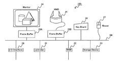
以下、本発明の実施形態について、図面を参照しつつ説明する。図1は、本発明の眼鏡レンズの光学特性補間方法を使用する眼鏡装用シミュレーションシステム100のハードウェア構成を示す。図1に示す実施形態の眼鏡装用シミュレーションシステム100は、累進屈折力レンズを用いた老眼視矯正用の眼鏡を装用した場合、どのような像を観察し得るかを被験者(詳しくは眼鏡購入予定者)に疑似体験させるためのシステムである。
Embodiments of the present invention will be described below with reference to the drawings. FIG. 1 shows a hardware configuration of a spectacle wearing
図1に示すように、眼鏡装用シミュレーションシステム100は、様々な処理を実行するコントローラ21、コントローラ21が実行する処理に関するプログラムや該処理中に生成あるいは入力される諸データを一時的に記憶する主記憶装置(RAM)22、コントローラ21が実行するプログラムを記憶するストレージデバイス23、を有する。コントローラ21が主となり実行する画像生成処理については後に詳述する。
As shown in FIG. 1, the spectacle wearing
また、眼鏡装用シミュレーションシステム100は、仮想レンズの光学性能を反映させたシミュレーション画像を表示するための画像表示部として機能するPCモニタ24、HMD25を有する。被検者はPCモニタ24等に映し出されたシミュレーション画像を見ることにより、眼鏡装用時の像の見え方を疑似体験する。システム100は、他にも、種々の処理を実行するコントローラ21に対して適宜指示を入力するための入力機器(キーボード26、マウス27)、眼鏡装用シミュレーションに必要な諸データを外部機器との間でやり取りするための入出力インターフェース28、PCモニタ24等の画像表示部にシミュレーション処理過程やシミュレーション処理結果に関する画像を送るために蓄えておくフレームバッファ29A、29Bを有する。また、各構成要素は互いにバスSBによって接続されている。
The glasses wearing
なお上記の通り、本実施形態では、ストレージデバイス23にコントローラ21が実行する処理に関するプログラムが予め記憶されている。但し、該プログラムは必ずしもストレージデバイス23に記憶されてある必要はない。例えば、入出力インターフェース28を介して情報読み出し機器を接続することにより、CD−ROMやDVD−ROMなど外部記憶媒体から該プログラムを供給することも可能である。さらには、オンライン接続されたデータベースにインターネット等を介して接続することにより、該データベースから該プログラムを供給することも可能である。
As described above, in the present embodiment, the
図2は、上記眼鏡装用シミュレーションシステム100に搭載される画像処理システム50に関するブロック図である。画像処理システム50において、シミュレーション画像の元となる原画像は、原画像入力部11を介して入力される。原画像入力部11は、図1に示す入出力インターフェース28を含む。原画像は、デジタルカメラなどからの実画像でも良いし、コンピュータグラフィックス(CG)ソフト等を用いて作成した人工画像でも良い。原画像入力部11は、入力された原画像に対応するデータ(原画像データ)を画像処理部12に伝送する。
FIG. 2 is a block diagram relating to the
第一パラメータ入力部13は、被検者が所望する眼鏡レンズ(仮想レンズ)の設計パラメータを入力するために設けられている。具体的には、第一パラメータ入力部13は、図1に示すキーボード25やマウス26が相当する。設計パラメータとしては、球面屈折力、乱視屈折力、乱視軸方向等が例示される。また、本実施形態のように累進屈折力レンズ装用時をシミュレーション対象とする場合、さらに加入屈折力、累進帯長、使用距離、なども設計パラメータに追加される。入力された設計パラメータは、仮想レンズデータ生成部14に出力される。
The first
仮想レンズデータ生成部14は、設計パラメータに基づいて、被検者が装用しようとする仮想の眼鏡レンズに関する光学データを生成する。光学データとは、例えば、光線追跡に必要な光学的情報、即ちレンズの屈折率、曲率、レンズ厚さや、レンズ間の距離などレンズ配置等である。生成された光学データは、画像処理部12に送信される。
The virtual lens
画像表示部16は、図1に示すPCモニタ24、HMD25等が相当する。ここで、HMD25のように内部に画像を観察するために用いられる光学系を備えている装置は、観察光学系データ生成部18に該光学系の設計パラメータを送信する。また、HMD25のように、視度調整可能な装置からは、視度調整の設定値も設計パラメータとして送信される。このように、光学系に固有の設計パラメータのみならず、視度調整の設定値といった各被験者によって変化するパラメータも使用することにより、被験者が仮想レンズを実際に装用した状態により近いシミュレーションを実現することができる。なお、各レンズデータ生成部14、18は、図1に示すコントローラ21、RAM22、ストレージデバイス23等を含む。
The
第二パラメータ入力部17は、被験者がシミュレーション当時装用している眼鏡等の眼鏡光学系の設計パラメータを入力するために設けられている。第二パラメータ入力部17により入力された設計パラメータは、観察光学系データ生成部18に送信される。なお図示しないが、第二パラメータ入力部17の代わりに、もしくは第二パラメータ入力部17とともに、眼鏡光学系の形状を測定する形状測定部を配設しても良い。形状測定部を使用すれば、被験者等が自ら装用している眼鏡光学系の設計パラメータが分からなくても、測定結果から光学データを生成することができる。なお、第二パラメータ入力部17も第一パラメータ入力部と同様、図1に示すキーボード25やマウス26が相当する。
The second parameter input unit 17 is provided for inputting design parameters of a spectacle optical system such as spectacles worn by the subject at the time of simulation. The design parameters input by the second parameter input unit 17 are transmitted to the observation optical system data generation unit 18. Although not shown, a shape measuring unit for measuring the shape of the spectacle optical system may be provided instead of the second parameter input unit 17 or together with the second parameter input unit 17. If the shape measuring unit is used, optical data can be generated from the measurement result without knowing the design parameters of the spectacle optical system worn by the subject or the like. The second parameter input unit 17 corresponds to the
観察光学系データ生成部18は、画像表示部16や第二パラメータ入力部17から送信された種々のパラメータに基づいて、シミュレーションに使用される全ての観察光学系に関する光学データを生成する。例えば、眼鏡を装用した被験者がHMD25を装着して仮想レンズ装用時のシミュレーションを行う場合、観察光学系データ生成部18は、被験者が装用している眼鏡およびHMD25内部の光学系双方の光学データを生成する。
The observation optical system data generation unit 18 generates optical data related to all observation optical systems used in the simulation based on various parameters transmitted from the
画像処理部12は歪みを持つシミュレーション画像を生成する。画像生成に関する処理については、後に詳述するが、画像処理部12は、原画像入力部11から出力された原画像データに、各レンズデータ生成部14、18から送信された光学データを用いて、シミュレーション画像を生成する。生成されたシミュレーション画像は画像出力部15(図1中、フレームバッファ29A、29Bに相当)を介して画像表示部16に出力される。このようなシステム50によって生成されたシミュレーション画像を観察することにより、被検者は仮想レンズを装用した時の像の見え方を疑似体験することが可能になる。
The
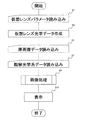
図3は、画像処理システム50が行う一連の画像処理の流れを示すフローチャートである。まず、ステップS1において、仮想レンズデータ生成部14が、第一パラメータ入力部13で入力された各種設計パラメータを読み込む(S1)。そして、仮想レンズデータ生成部14は、該設計パラメータに基づいて、被検者の所望する仮想のレンズを設計し、後のステップで行われる光線追跡に必要な光学データを生成する(S3)。
FIG. 3 is a flowchart showing a flow of a series of image processing performed by the
また、原画像入力部11は、S5において、パーソナルコンピュータやデジタルカメラ等の外部機器もしくはシステム100の内蔵メモリから原画像を読み込み、原画像データを生成する。原画像データは、奥行き方向の距離情報を持つとより望ましい。ここでCGソフトなどを利用して作成された人工画像は、作成時に上記の距離情報を付与することが可能である。そのため人工画像を用いた場合、S5において、該人工画像から距離情報を取得することは比較的容易である。しかし、デジタルカメラなどから取り込んだ実画像は通常距離情報を有していないため、平面的な画像データしか取得できない。従って実画像を取り込む場合には、該実画像に基づいて距離情報を取得する、距離情報取得工程をS5にさらに組み込む事がより望ましい。距離情報取得行程としては、例えば、予め複数の視点から撮影した実画像を用意し、ステレオマッチング法等を用いて距離情報を取得する方法等が挙げられる。
In S5, the original
次いで、画像処理部12は、観察光学系データ生成部18によって生成された各観察光学系の光学データを読み込む(S7)。そして、S3およびS7で取得した各光学データを用いて、S5で読み込んだ原画像データにボケや歪みに関する処理(画像処理)を施し、シミュレーション画像に対応する画像データを生成する(S9)。S9における画像処理は後に詳述する。S9によって生成された画像データは、画像出力部15を介してPCモニタ24等の画像表示部16によってシミュレーション画像として表示される(S11)。
Next, the
次に、画像処理部12が行う画像処理(図3中、S9)について詳説する。なお、以下の説明においては、画像処理の一連の工程において使用される画像(および該画像のデータ)を以下のように定義する。まずデジタルカメラ等から原画像入力部を介して入力される原画像をO、原画像データをODとする。また、仮想レンズを介して原画像Oを観察した時に得られる画像、つまり仮想レンズによる歪みを持つ画像を仮想レンズ画像P、該画像のデータをPDとする。また、画像表示部16に表示される画像をシミュレーション画像Q、該画像のデータをQDとする。また、以下の説明においては、便宜上、各画像内の点像の位置を、光学中心を原点として互いに直交するX軸とY軸の二つの軸の座標によって規定する。特に、各画像を形成する複数の画素の位置を、X,y軸の各軸の整数座標によって規定している。つまり、該画像処理は、観察光学系を介して仮想レンズ装用時のシミュレーションを行う被験者が、観察光学系に起因する歪みは持たず仮想レンズに起因する歪みのみを持つ画像(仮想レンズ画像P)を観察することができるように、原画像O(原画像データOD)からシミュレーション画像Q(シミュレーション画像データQD)を生成する処理といえる。
Next, image processing (S9 in FIG. 3) performed by the
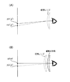
画像処理を説明するに先立って、図4を参照しつつ、上記の各画像の関係について概説する。上記の通り、仮想レンズ画像Pは原画像Oに仮想レンズによる歪み成分を付与した画像である。つまり、図4(A)に示すように、仮想レンズ画像P中の位置(x',y')にある点像pを見る被験者の目には、仮想レンズの歪みによって、原画像O中の位置(x'',y'')にある点像oが写る。つまり、観察光学系を用いずにシミュレーションを行う場合には、仮想レンズ画像Pをシミュレーション画像として表示すれば、被験者は、仮想レンズ装用時の歪みやボケを疑似体験することができる。 Prior to the description of the image processing, the relationship between the images will be outlined with reference to FIG. As described above, the virtual lens image P is an image obtained by adding a distortion component due to the virtual lens to the original image O. In other words, as shown in FIG. 4A, the eye of the subject who sees the point image p at the position (x ′, y ′) in the virtual lens image P is in the original image O due to the distortion of the virtual lens. A point image o at the position (x ″, y ″) is captured. That is, when a simulation is performed without using the observation optical system, if the virtual lens image P is displayed as a simulation image, the subject can experience a simulated experience of distortion and blurring when wearing the virtual lens.
しかし、観察光学系を介してシミュレーションを行う場合、該観察光学系自体に起因する歪みによって、図4(B)に示すように、シミュレーション画像Qにおいて、点像pは、位置(x,y)にある点像qとして観察されてしまう。 However, when the simulation is performed via the observation optical system, the point image p is located at the position (x, y) in the simulation image Q as shown in FIG. 4B due to distortion caused by the observation optical system itself. Is observed as a point image q.
以上を踏まえると、シミュレーション画像Q中の点像qに対応する仮想レンズ画像P中の点像p、さらには点像pに対応する原画像O中の点像oの位置を光線追跡によって求める。そして点像oの輝度値(R、G、Bの各データ)を点像qの輝度値として設定することにより、観察光学系に起因する歪みは取りつつ、仮想レンズに起因する歪みを持ったシミュレーション画像Qを生成できることがわかる。 Based on the above, the position of the point image p in the virtual lens image P corresponding to the point image q in the simulation image Q and the position of the point image o in the original image O corresponding to the point image p are obtained by ray tracing. Then, by setting the luminance value of the point image o (each data of R, G, B) as the luminance value of the point image q, the distortion caused by the observation optical system was taken and the distortion caused by the virtual lens was obtained. It can be seen that the simulation image Q can be generated.
図5は、図3中、S9に示す画像処理の流れを詳細に示すフローチャートである。図6は、図5に示す画像処理において行われる光線追跡の一例を示す説明図である。なお、図6では、説明の便宜上、各画像の一部を拡大し、画素を点として表している。 FIG. 5 is a flowchart showing in detail the flow of the image processing shown in S9 in FIG. FIG. 6 is an explanatory diagram showing an example of ray tracing performed in the image processing shown in FIG. In FIG. 6, for convenience of explanation, a part of each image is enlarged and pixels are represented as dots.
まずS41において、画像処理部12は、シミュレーション画像データQDを生成するための作業領域をRAM22上に確保する(画像データセット)。次いで、画像処理部12は、シミュレーション画像Qの全画素について画像処理が行われているか否かを判断する(S13)。具体的には、画像処理の対象となる画素の座標値がS41で各画素に割り振られた座標値の最大値を超えたか否かを判断する。
First, in S41, the
S43において、まだ画像処理が行われていない画素があると判断した場合(S43:NO)には、S45へ進む。S45において、画像処理部12は、シミュレーション画像Qを構成する画素qのうち、位置(x,y)にある画素q(x,y)を処理対象の画素として指定する(図6(A)参照)。次いでS45の処理が終わると、画像処理部12は、S47に進む。
If it is determined in S43 that there is a pixel that has not undergone image processing (S43: NO), the process proceeds to S45. In S45, the
S47では、観察光学系を介してシミュレーション画像Qを見た時において、該画像Q中の各画素の配置位置で見える像が、仮想レンズ画像Pのどの位置にある像なのかを光線追跡により求める(第一光線追跡処理)。つまり、画素q(x,y)に対応する仮想レンズ画像P上の位置(x’,y’)を光線追跡によって算出する。S47の光線追跡は、図3中S7で読み込まれた観察光学系の光学データに基づいて行われる。S47で光線追跡を行うことにより、画素q(x,y)に映し出されるべき点像は、仮想レンズ画像P上の位置(x',y')にある点像pであることがわかる(図5(B)参照)。換言すれば、観察光学系を介して仮想レンズ画像Pを見た場合、仮想レンズ画像P上の位置(x’,y’)にある点像p(x',y')は、観察光学系の歪みによって、画素q(x,y)に映し出された点像として観察されることがわかる。ここで、第一光線追跡処理により算出された点は、観察光学系の歪みによって、必ずしも画素の位置と一致するとは限らない。そのため、pは点像と表記し、該点像pの位置x'やy'は整数値を取らない(つまり、図6(B)に示すように、点p(x',y')が各画素間に位置する)場合もあると想定する。後述の第二光線追跡処理に関しても同様である。 In S47, when the simulation image Q is viewed through the observation optical system, it is determined by ray tracing which position in the virtual lens image P the image seen at the arrangement position of each pixel in the image Q is. (First ray tracing process). That is, the position (x ′, y ′) on the virtual lens image P corresponding to the pixel q (x, y) is calculated by ray tracing. The ray tracing in S47 is performed based on the optical data of the observation optical system read in S7 in FIG. By performing ray tracing in S47, it is understood that the point image to be displayed on the pixel q (x, y) is the point image p at the position (x ′, y ′) on the virtual lens image P (FIG. 5 (B)). In other words, when the virtual lens image P is viewed through the observation optical system, the point image p (x ′, y ′) at the position (x ′, y ′) on the virtual lens image P is the observation optical system. It can be seen that the image is observed as a point image projected on the pixel q (x, y) due to the distortion of. Here, the point calculated by the first ray tracing process does not necessarily coincide with the pixel position due to distortion of the observation optical system. Therefore, p is expressed as a point image, and the position x ′ or y ′ of the point image p does not take an integer value (that is, as shown in FIG. 6B, the point p (x ′, y ′) is It is assumed that it may be located between each pixel). The same applies to the second ray tracing process described later.
次いで、S49で、仮想レンズ画像Pの点像p(x',y')が、原画像Oのどの位置にある像なのかを光線追跡により求める(第二光線追跡処理)。S49の光線追跡は、図3中S3で読み込まれた仮想レンズの光学データに基づいて行われる。S49で光線追跡を行うことにより、仮想レンズ画像Pの点像p(x',y')が、原画像O上では位置(x'',y'')にあることがわかる(図6(C)参照)。換言すれば、仮想レンズを装用して原画像Oを見た場合、位置(x'',y'')にある点像oは、該仮想レンズの歪みによって、位置(x',y')にある点像pとして観察されることがわかる。 Next, in S49, the position where the point image p (x ′, y ′) of the virtual lens image P is in the original image O is obtained by ray tracing (second ray tracing process). The ray tracing in S49 is performed based on the optical data of the virtual lens read in S3 in FIG. By performing ray tracing in S49, it can be seen that the point image p (x ′, y ′) of the virtual lens image P is at the position (x ″, y ″) on the original image O (FIG. 6 ( C)). In other words, when the original image O is viewed using the virtual lens, the point image o at the position (x ″, y ″) is positioned at the position (x ′, y ′) due to the distortion of the virtual lens. It can be seen that it is observed as a point image p.
第一光線追跡処理で説明した通り、第二光線追跡処理により求められた点像oの位置(x'',y'')は、必ずしも整数値を取るとは限らない。従って、点像o(x'',y'')の輝度値を算出するために、原画像データODにおける各画素の輝度値を用いて補間処理を行う(S51)。具体的には、図6(C)に示すように、求められた点像oの周囲にある4つの画素a〜dの輝度値を平均化することにより点像o(x'',y'')の輝度値を算出する。この際、処理速度を優先するのであれば、4つの画素a〜dの輝度値を単に平均化すればよい。また、画像の精度(つまり、原画像により近い色や明るさの再現)を優先するのであれば、各画素a〜dと点像o(x'',y'')間の距離La〜Ldに基づく重み付けをした上で各輝度値を平均化する。 As described in the first ray tracing process, the position (x ″, y ″) of the point image o obtained by the second ray tracing process does not necessarily take an integer value. Therefore, in order to calculate the luminance value of the point image o (x ″, y ″), interpolation processing is performed using the luminance value of each pixel in the original image data OD (S51). Specifically, as shown in FIG. 6C, the point image o (x ″, y ′) is obtained by averaging the luminance values of the four pixels a to d around the obtained point image o. ') Calculate the luminance value. At this time, if priority is given to the processing speed, the luminance values of the four pixels a to d may be simply averaged. If priority is given to image accuracy (that is, reproduction of colors and brightness closer to the original image), the distances La to Ld between the pixels a to d and the point image o (x ″, y ″). Each luminance value is averaged after weighting based on.
なお、二回の光線追跡処理(S47、S49)の結果(点像o(x'',y''))が、原画像Oにおける画面外に位置するおそれもある。そのため、シミュレーション画像Qは、原画像Oよりも若干小さめに設定される(図6(A)、(C)参照)。これにより、点像o(x'',y'')が、シミュレーション画像における画面外に位置したとしても、原画像Oの範囲内にあるため、確実に補間処理を行うことができる。 Note that the result of the two ray tracing processes (S47, S49) (point image o (x ″, y ″)) may be located outside the screen in the original image O. Therefore, the simulation image Q is set slightly smaller than the original image O (see FIGS. 6A and 6C). As a result, even if the point image o (x ″, y ″) is located outside the screen in the simulation image, since it is within the range of the original image O, the interpolation process can be reliably performed.
次いで、S51の補間処理によって算出された点像o(x'',y'')の輝度値を画素q(x,y)の輝度値として設定する(S53)。そして、x,yの値を更新し(S55)、次の画素qに対する上記一連の処理を繰り返す。 Next, the luminance value of the point image o (x ″, y ″) calculated by the interpolation processing in S51 is set as the luminance value of the pixel q (x, y) (S53). Then, the values of x and y are updated (S55), and the above-described series of processing for the next pixel q is repeated.
上記S43〜S55までの処理を繰り返して、S43において、全画素について処理が終っていると判断すると、画像処理部12は、S57に進む。S57において、画像処理部12は、仮想レンズに起因して発生する非点収差や度数誤差、被験者の目の調整力の強弱などに応じたS55で生成されたシミュレーション画像Qにボケを発生させる処理を行う。S57のボケ発生処理が終了すると、図3に示すS9の画像処理を終了する。
When the processes from S43 to S55 are repeated and it is determined in S43 that the process has been completed for all the pixels, the
このように、本実施形態の画像処理部12は、シミュレーション画像Qの画素ごとに、光線追跡を行って各画素の輝度値(R、G、Bの各データ)を算出することにより、該シミュレーション画像Qを生成する。これにより、観察光学系に起因する歪みの補正を含み、仮想レンズに起因する歪みを持ったシミュレーション画像Qが生成される。また、該画像Qにさらに仮想レンズの非点収差等に基づくボケも発生させる。これにより、被験者は仮想レンズ実装用時により近い像の見え方を疑似体験することができる。
As described above, the
以上が本発明の実施形態である。なお、本発明に係る眼鏡装用シミュレーションシステムは、他の方法によっても上記シミュレーション画像を生成することができる。 The above is the embodiment of the present invention. The spectacle wearing simulation system according to the present invention can generate the simulation image also by other methods.
一般的に連続的な曲面からなる光学系の歪曲収差は空間的に急激に変化することは無い。従って、xおよびyを用いたx''およびy''の関数を生成することができる。該関数の生成は、例えば以下のようにして行われる。すなわち、予めシミュレーション画像Q上の基準となるいくつかの画素、もしくは位置(以下、単に基準点という)に関して光線追跡(図5、S47、S49)を行う。そして、該基準点に対応する原画像Oにおける位置を算出する。そして、各基準点間を補間することにより、シミュレーション画像Q上の画素の位置を表すxおよびyを用いて、該位置(x,y)に対応する原画像上の位置を表すx''およびy''の関数を求める。 In general, the distortion of an optical system composed of a continuous curved surface does not change abruptly in space. Therefore, a function of x ″ and y ″ using x and y can be generated. The function is generated as follows, for example. That is, ray tracing (FIG. 5, S47, S49) is performed in advance on some pixels or positions (hereinafter simply referred to as reference points) serving as a reference on the simulation image Q. Then, the position in the original image O corresponding to the reference point is calculated. Then, by interpolating between the respective reference points, x ″ representing the position of the pixel on the simulation image Q and y ″ representing the position on the original image corresponding to the position (x, y) and Find the function of y ''.
具体的には、まず、基準点に関する第二光線追跡処理(S49参照)の結果に基づいて、x'およびy'は、それぞれ以下の関数で表すことができる。
x'=f(x'',y'')・・・(1)
y'=g(x'',y'')・・・(2)
(1)、(2)の各関数を逆関数化することにより、以下の関数(3)、(4)が導出される。
x''=F(x',y')・・・(3)
y''=G(x',y')・・・(4)
Specifically, first, x ′ and y ′ can be expressed by the following functions based on the result of the second ray tracing process (see S49) related to the reference point.
x ′ = f (x ″, y ″) (1)
y ′ = g (x ″, y ″) (2)
The following functions (3) and (4) are derived by converting the functions of (1) and (2) into inverse functions.
x ″ = F (x ′, y ′) (3)
y ″ = G (x ′, y ′) (4)
また、基準点に関する第一光線追跡処理(S47参照)の結果に基づいて、x'およびy'は、それぞれ以下の関数で表すことができる。
x'=H(x,y)・・・(5)
y'=I(x,y)・・・(6)
Also, based on the result of the first ray tracing process (see S47) regarding the reference point, x ′ and y ′ can be expressed by the following functions, respectively.
x ′ = H (x, y) (5)
y ′ = I (x, y) (6)
ここで、関数(3)、(4)に関数(5)、(6)を代入することにより、xおよびyを用いたx''およびy''の関数(7)、(8)が導出される。
x''=F(H(x,y)、I(x,y))・・・(7)
y''=G(H(x,y)、I(x,y))・・・(8)
Here, by substituting the functions (5) and (6) into the functions (3) and (4), the functions (7) and (8) of x ″ and y ″ using x and y are derived. Is done.
x ″ = F (H (x, y), I (x, y)) (7)
y ″ = G (H (x, y), I (x, y)) (8)
上記の各関数(7)、(8)が導出されれば、以後の処理は、光線追跡等を行うことなく、該関数(7)、(8)を用いることにより、簡易かつ迅速にシミュレーション画像Qの生成を行うことができる。 If the above functions (7) and (8) are derived, the subsequent processing can be performed easily and quickly by using the functions (7) and (8) without performing ray tracing or the like. Q can be generated.
さらに、観察光学系が単焦点眼鏡レンズの場合には、本発明に係る眼鏡装用シミュレーションシステムは、以下のようにしてシミュレーション画像を生成することも可能である。 Further, when the observation optical system is a single-focus spectacle lens, the spectacle wearing simulation system according to the present invention can also generate a simulation image as follows.
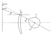
図7は、眼鏡レンズ(単焦点レンズ)と眼と画像との光学的配置および光線配置を示した図である。図7において、Eは眼を、Ecは眼球回旋点を、Lは眼鏡レンズを示す。βは眼鏡レンズLの光軸(と平行な線)と視線がなす角(眼の回旋角、単位:度)、αは眼鏡レンズLにより屈折すると視線と一致する光線と光軸(と平行な線)がなす角(単位:度)を表す。角度αを規定する視線の延長線上には、シミュレーション画像での画素q(x,y)がある。角度βを規定する光線の延長線上には、仮想レンズ画像の点像p(x',y')がある。つまり、各画像における任意の位置(例えば、画像や点像)は、x軸,y軸の座標による定義ではなく、二つの角度α、βによっても定義することができる。 FIG. 7 is a diagram showing an optical arrangement and a ray arrangement of a spectacle lens (single focus lens), an eye, and an image. In FIG. 7, E indicates an eye, Ec indicates an eyeball rotation point, and L indicates a spectacle lens. β is an angle formed by the line of sight of the optical axis of the spectacle lens L (a line parallel to the optical axis) (rotation angle of the eye, unit: degree), and α is a light beam that is refracted by the spectacle lens L and coincides with the optical axis. This represents the angle (unit: degrees) formed by the line. A pixel q (x, y) in the simulation image is on the extension of the line of sight that defines the angle α. There is a point image p (x ′, y ′) of the virtual lens image on the extension line of the light ray that defines the angle β. That is, an arbitrary position (for example, an image or a point image) in each image can be defined not by the x-axis and y-axis coordinates but by two angles α and β.
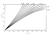
図8は、観察光学系(単焦点レンズ)の歪みを除去する画像処理に用いられる光線追跡結果の一例をレンズの球面屈折力S(単位:ディオプター)の変化とともに角度αとβの関係で示したグラフである。横軸は角度αを横軸は角度βを表す。またグラフ中、最も左側が、球面屈折力S=+8.00の角度αとβの関係を示す曲線の束で、以降順に、最も右側の曲線束(球面屈折力S=−12.00)まで、4.00ディオプターずつ球面屈折力Sを変化させたときの角度αとβの関係を示す。同じ屈折力のレンズでもベースカーブの選択によってαとβの関係は若干変化する。曲線の束は、実線が比較的ベースカーブが深い形状のレンズ、破線が比較的ベースカーブが浅い形状のレンズ、一点鎖線が前二者の略中間のベースカーブを持つレンズを意味する。 FIG. 8 shows an example of the result of ray tracing used for image processing for removing distortion of the observation optical system (single focus lens) in relation to the angles α and β along with the change of the spherical refractive power S (unit: diopter) of the lens. It is a graph. The horizontal axis represents the angle α, and the horizontal axis represents the angle β. In the graph, the leftmost curve is a bundle of curves indicating the relationship between the angles α and β of the spherical power S = + 8.00, and the rightmost curve bundle (spherical power S = −12.00) in order. The relationship between the angles α and β when the spherical refractive power S is changed by 4.00 diopters is shown. Even with lenses having the same refractive power, the relationship between α and β changes slightly depending on the selection of the base curve. The bundle of curves means a lens having a solid line having a relatively deep base curve, a broken line having a relatively shallow base curve, and a dot-and-dash line having a substantially intermediate base curve.
図8に示すグラフから分かるように、球面屈折力Sが+方向に大きくなればなるほど、α<βという傾向にある。該傾向は、レンズ周辺になればなるほど顕著に表れる。つまり、レンズ周辺では、物体がより拡大されて見える、換言すれば糸巻き型の歪曲収差が発生している。また、球面屈折力Sが−方向に大きくなればなるほど、α>βという傾向にある。該傾向もレンズ周辺になればなるほど顕著に表れる。つまり、レンズ周辺では、物体はより縮小されて見える、換言すれば樽型の歪曲収差が発生している。なお、球面屈折力S=0.00のときは、ベースカーブの如何を問わず、αとβは等しい。つまり、歪曲収差は発生していない。 As can be seen from the graph shown in FIG. 8, the larger the spherical refractive power S in the + direction, the more α <β. This tendency becomes more prominent as the lens becomes closer to the periphery. That is, around the lens, the object appears to be magnified, in other words, a pincushion type distortion aberration occurs. Further, as the spherical refractive power S increases in the-direction, there is a tendency that α> β. This tendency becomes more prominent as the lens becomes closer to the periphery. That is, around the lens, the object appears to be further reduced, in other words, barrel distortion occurs. Note that when the spherical refractive power S = 0.00, α and β are equal regardless of the base curve. That is, no distortion is generated.
ここで、上記のように、単焦点レンズは、球面屈折力が定まると歪曲収差の発生量もおよそ一義的に定まるという特徴がある。つまり、図8に示すグラフは単焦点レンズである限り、略不変である。以上よりシミュレーション画像生成時は、図8に示すグラフを、テーブルとしてあるいは球面屈折力S毎の各曲線(の束)を規定する関数として、予め画像処理部12に与えておく。そして、被験者が装用中の単焦点レンズに関する、少なくとも球面屈折力、より好ましくはベースカーブを入力することにより、該単焦点レンズの歪曲収差が算出される。次いで、該歪曲収差を打ち消すように原画像O(より厳密には、仮想レンズ画像P)を補正することにより、第一光線追跡処理を一切行わずに、シミュレーション画像Qを生成することができる。
Here, as described above, the single focus lens has a feature that the amount of distortion aberration is determined uniquely when the spherical refractive power is determined. That is, the graph shown in FIG. 8 is substantially unchanged as long as it is a single focus lens. As described above, when generating a simulation image, the graph shown in FIG. 8 is given to the
12 画像処理部
21 コントローラ
22 RAM
50 画像処理システム
L 眼鏡レンズ
100 眼鏡装用シミュレーションシステム
12
50 Image Processing System
Claims (18)
前記仮想レンズに関する複数のパラメータを入力する第一の入力手段と、
前記仮想レンズに関する複数のパラメータに基づいて、前記仮想レンズの光学データを生成する第一の光学データ生成手段と、
前記観察光学系に関する複数のパラメータを入力する第二の入力手段と、
前記観察光学系に関する複数のパラメータに基づいて、前記像に対応するシミュレーション画像を観察するために用いられる観察光学系の光学データを生成する第二の光学データ生成手段と、
前記仮想レンズの光学データおよび前記観察光学系の光学データに基づいて、原画像に、前記仮想レンズの持つ歪みを付与し、前記観察光学系の持つ歪みを打ち消すような画像処理を施して前記シミュレーション画像を生成する画像生成手段と、
を有することを特徴とする眼鏡装用シミュレーションシステム。 In an eyeglass wearing simulation system that allows a subject to experience a simulated experience through an image display device, an image that can be observed when wearing a virtual eyeglass lens,
First input means for inputting a plurality of parameters relating to the virtual lens;
First optical data generating means for generating optical data of the virtual lens based on a plurality of parameters relating to the virtual lens;
Second input means for inputting a plurality of parameters relating to the observation optical system;
Second optical data generating means for generating optical data of an observation optical system used for observing a simulation image corresponding to the image based on a plurality of parameters relating to the observation optical system;
Based on the optical data of the virtual lens and the optical data of the observation optical system, the simulation is performed by applying image processing to impart distortion to the virtual image to the original image and cancel the distortion of the observation optical system. Image generating means for generating an image ;
An eyeglass wearing simulation system characterized by comprising:
前記画像生成手段は、前記シミュレーション画像を形成する全ての画素について、前記観察光学系に関する光線追跡と前記仮想レンズに関する光線追跡を行うことにより、各画素の位置に対応する原画像の位置を検出する検出手段を有し、
前記原画像の位置における輝度値を各画素の輝度値として設定することにより、前記シミュレーション画像を生成することを特徴とする眼鏡装用シミュレーションシステム。 The spectacle wearing simulation system according to claim 1,
The image generation means detects the position of the original image corresponding to the position of each pixel by performing ray tracing for the observation optical system and ray tracing for the virtual lens for all the pixels forming the simulation image. Having detection means;
An eyeglass-wearing simulation system that generates the simulation image by setting a luminance value at a position of the original image as a luminance value of each pixel.
前記画像生成手段は、前記シミュレーション画像を形成する画素のうち、基準となる複数の画素について、前記観察光学系に関する光線追跡と前記仮想レンズに関する光線追跡を行い、該光線追跡の結果から得られた、前記シミュレーション画像内の像と前記原画像内の像との位置関係を表す所定の関数を用いて、各画素に対応する前記原画像の位置を算出し、被験者が各画素の位置で見ることになる原画像の輝度値を各画素の輝度値として設定することにより、前記シミュレーション画像を生成することを特徴とする眼鏡装用シミュレーションシステム。 The spectacle wearing simulation system according to claim 1,
The image generating means performs ray tracing for the observation optical system and ray tracing for the virtual lens for a plurality of reference pixels among the pixels forming the simulation image, and is obtained from the result of the ray tracing. The position of the original image corresponding to each pixel is calculated using a predetermined function representing the positional relationship between the image in the simulation image and the image in the original image, and the subject sees at the position of each pixel. The simulation image is generated by setting the luminance value of the original image to be the luminance value of each pixel.
前記観察光学系は、単焦点レンズであり、
前記画像生成手段は、前記仮想レンズに起因する歪みを持つ画像に、眼の回旋角、前記観察光学系により屈折すると視線と一致する光線と光軸がなす角、および前記仮想レンズの屈折力によって規定される前記観察光学系の歪曲収差を打ち消すような画像処理を施すことにより、前記シミュレーション画像を生成することを特徴とする眼鏡装用シミュレーションシステム。 The spectacle wearing simulation system according to claim 1,
The observation optical system is a single focus lens,
The image generation unit is configured to change an image having distortion caused by the virtual lens by an eye rotation angle, an angle formed by a light beam that matches a line of sight when refracted by the observation optical system, and a refractive power of the virtual lens. An eyeglass-wearing simulation system that generates the simulation image by performing image processing that cancels distortion aberration of the observation optical system that is defined.
前記観察光学系は、前記画像表示装置内に設けられた光学系を含むことを特徴とする眼鏡装用シミュレーションシステム。 In the glasses wearing simulation system according to any one of claims 1 to 4 ,
The eyeglass wearing simulation system, wherein the observation optical system includes an optical system provided in the image display device.
前記観察光学系に関する形状を測定する形状測定手段をさらに有し、
前記第二の光学データ生成手段は、測定された前記観察光学系に関する形状に基づいて、前記観察光学系の光学データを生成することを特徴とする眼鏡装用シミュレーションシステム。 In the glasses wearing simulation system according to any one of claims 1 to 7 ,
It further has shape measuring means for measuring the shape related to the observation optical system ,
The second optical data generation unit generates optical data of the observation optical system based on the measured shape related to the observation optical system.
前記仮想の眼鏡レンズは、累進屈折力レンズであることを特徴とする眼鏡装用シミュレーションシステム。 In the spectacles wearing simulation system according to any one of claims 1 to 8 ,
The virtual spectacle lens is a progressive-power lens.
前記仮想レンズに関する複数のパラメータを入力する第一の入力工程と、
前記仮想レンズに関する複数のパラメータに基づいて、前記仮想レンズの光学データを生成する第一の光学データ生成工程と、
前記観察光学系に関する複数のパラメータを入力する第二の入力工程と、
前記観察光学系に関する複数のパラメータに基づいて、前記像に対応するシミュレーション画像を観察するために用いられる観察光学系の光学データを生成する第二の光学データ生成工程と、
前記第一、前記第二の各光学データ生成工程で生成された前記第一、前記第二の各光学データに基づいて、原画像に、前記仮想レンズの持つ歪みを付与するとともに、前記観察光学系の持つ歪みを打ち消すような画像処理を施して画像を生成する画像生成工程と、
を有することを特徴とする画像生成方法。 An image generation method in a spectacle wearing simulation system that allows a subject to experience a pseudo experience through an image display device when observing when wearing a virtual spectacle lens,
A first input step of inputting a plurality of parameters relating to the virtual lens;
A first optical data generation step of generating optical data of the virtual lens based on a plurality of parameters relating to the virtual lens;
A second input step for inputting a plurality of parameters relating to the observation optical system;
A second optical data generation step for generating optical data of an observation optical system used for observing a simulation image corresponding to the image based on a plurality of parameters relating to the observation optical system;
Based on the first and second optical data generated in the first and second optical data generation steps, the distortion of the virtual lens is imparted to the original image, and the observation optics An image generation process for generating an image by performing image processing that cancels the distortion of the system;
An image generation method characterized by comprising:
前記画像生成工程は、
前記シミュレーション画像における画素について、前記観察光学系に関する光線追跡と前記仮想レンズに関する光線追跡を行うことにより、該画素の位置に対応する原画像の位置を検出する検出工程と、
前記検出工程により検出された前記原画像の位置における輝度値を前記画素の輝度値として設定する設定工程と、を有し、
前記シミュレーション画像における全ての画素について、前記検出工程と前記設定工程を行うことにより、前記シミュレーション画像を生成する画像生成方法。 The image generation method according to claim 10 .
The image generation step includes
A detection step of detecting the position of the original image corresponding to the position of the pixel by performing ray tracing relating to the observation optical system and ray tracing relating to the virtual lens for the pixel in the simulation image;
Setting a luminance value at the position of the original image detected by the detection step as a luminance value of the pixel,
An image generation method for generating the simulation image by performing the detection step and the setting step for all pixels in the simulation image.
前記画像生成工程は、
前記シミュレーション画像を形成する画素のうち、基準となる複数の画素について、前記観察光学系に関する光線追跡と前記仮想レンズに関する光線追跡を行うことにより、該画素の位置に対応する原画像の位置を検出する検出工程と、
前記検出工程の検出結果に基づき、前記シミュレーション画像内の像と前記原画像内の像との位置関係を表す所定の関数を生成する関数生成工程と、
前記関数生成工程により生成された前記所定の関数を用いて、各画素に対応する前記原画像の位置を算出する位置算出工程と、を含み、
各画素の位置に対応する原画像の位置での輝度値を各画素の輝度値として設定することにより、前記シミュレーション画像を生成する画像生成方法。 The image generation method according to claim 10 .
The image generation step includes
Among a plurality of pixels forming the simulation image, the position of the original image corresponding to the position of the pixel is detected by performing ray tracing for the observation optical system and ray tracing for the virtual lens for a plurality of reference pixels. Detecting step to
Based on the detection result of the detection step, a function generation step for generating a predetermined function representing a positional relationship between the image in the simulation image and the image in the original image;
A position calculating step of calculating the position of the original image corresponding to each pixel using the predetermined function generated by the function generating step,
An image generation method for generating the simulation image by setting a luminance value at a position of an original image corresponding to a position of each pixel as a luminance value of each pixel.
前記画像生成工程は、前記仮想レンズに起因する歪みを持つ画像に、眼の回旋角、前記観察光学系により屈折すると視線と一致する光線と光軸がなす角、および前記仮想レンズの屈折力によって規定される前記観察光学系の歪曲収差を打ち消すような画像処理を施すことにより、前記シミュレーション画像を生成する画像生成方法。 The image generation method according to claim 10 .
In the image generation step, an image having distortion caused by the virtual lens is determined based on the rotation angle of the eye, the angle formed by the optical axis and the ray that matches the line of sight when refracted by the observation optical system, and the refractive power of the virtual lens. An image generation method for generating the simulation image by performing image processing that cancels the distortion aberration of the prescribed observation optical system.
前記観察光学系は、前記画像表示装置内に設けられた光学系を含む画像生成方法。 The image generation method according to any one of claims 10 to 13 ,
The image generation method, wherein the observation optical system includes an optical system provided in the image display device.
前記観察光学系に関する複数のパラメータの一つに、前記画像表示装置において、前記被験者に対応して実行された視度調整に関する設定値を含む画像生成方法。 The image generation method according to any one of claims 10 to 14 ,
An image generation method including, as one of a plurality of parameters related to the observation optical system, a setting value related to diopter adjustment performed for the subject in the image display device.
前記観察光学系は、被験者が現在装用中の眼鏡光学系を含む画像生成方法。 The image generation method according to any one of claims 10 to 15 ,
The observation optical system is an image generation method including a spectacle optical system currently worn by a subject.
前記観察光学系に関する形状を測定する形状測定工程をさらに有し、
前記第二の光学データ生成工程において、測定された前記観察光学系に関する形状に基づいて、前記観察光学系の光学データを生成する画像生成方法。 The image generation method according to any one of claims 10 to 16 ,
A shape measuring step of measuring a shape related to the observation optical system ;
An image generation method for generating optical data of the observation optical system based on the measured shape related to the observation optical system in the second optical data generation step .
前記仮想の眼鏡レンズは、累進屈折力レンズである画像生成方法。 The image generation method according to any one of claims 10 to 17 ,
The virtual spectacle lens is a progressive power lens.
Priority Applications (1)
| Application Number | Priority Date | Filing Date | Title |
|---|---|---|---|
| JP2004079399A JP4477909B2 (en) | 2004-03-19 | 2004-03-19 | Glasses wearing simulation system and image generation method |
Applications Claiming Priority (1)
| Application Number | Priority Date | Filing Date | Title |
|---|---|---|---|
| JP2004079399A JP4477909B2 (en) | 2004-03-19 | 2004-03-19 | Glasses wearing simulation system and image generation method |
Publications (2)
| Publication Number | Publication Date |
|---|---|
| JP2005261690A JP2005261690A (en) | 2005-09-29 |
| JP4477909B2 true JP4477909B2 (en) | 2010-06-09 |
Family
ID=35086827
Family Applications (1)
| Application Number | Title | Priority Date | Filing Date |
|---|---|---|---|
| JP2004079399A Expired - Lifetime JP4477909B2 (en) | 2004-03-19 | 2004-03-19 | Glasses wearing simulation system and image generation method |
Country Status (1)
| Country | Link |
|---|---|
| JP (1) | JP4477909B2 (en) |
Cited By (1)
| Publication number | Priority date | Publication date | Assignee | Title |
|---|---|---|---|---|
| WO2014030403A1 (en) | 2012-08-20 | 2014-02-27 | Hoya株式会社 | Simulation device, simulation system, simulation method and simulation program |
Families Citing this family (8)
| Publication number | Priority date | Publication date | Assignee | Title |
|---|---|---|---|---|
| EP1862110A1 (en) | 2006-05-29 | 2007-12-05 | Essilor International (Compagnie Generale D'optique) | Method for optimizing eyeglass lenses |
| JP5341462B2 (en) * | 2008-10-14 | 2013-11-13 | キヤノン株式会社 | Aberration correction method, image processing apparatus, and image processing system |
| WO2010044383A1 (en) * | 2008-10-17 | 2010-04-22 | Hoya株式会社 | Visual field image display device for eyeglasses and method for displaying visual field image for eyeglasses |
| JP5632245B2 (en) * | 2010-09-27 | 2014-11-26 | Hoya株式会社 | Eyeglass field image display device |
| CN105452834A (en) * | 2013-07-18 | 2016-03-30 | 埃西勒国际通用光学公司 | A method for determining a visual effect of an ophthalmic lens |
| JP6220627B2 (en) * | 2013-10-17 | 2017-10-25 | 株式会社ニコン・エシロール | Measurement method, spectacle lens selection method, spectacle lens design method, spectacle lens manufacturing method, and measurement apparatus |
| JP2022073094A (en) * | 2020-10-30 | 2022-05-17 | セイコーエプソン株式会社 | Optical module and virtual image display device |
| CN116300094B (en) * | 2023-03-17 | 2025-07-29 | 浙江炽云科技有限公司 | Visual analysis method for head-up display device and related equipment |
-
2004
- 2004-03-19 JP JP2004079399A patent/JP4477909B2/en not_active Expired - Lifetime
Cited By (2)
| Publication number | Priority date | Publication date | Assignee | Title |
|---|---|---|---|---|
| WO2014030403A1 (en) | 2012-08-20 | 2014-02-27 | Hoya株式会社 | Simulation device, simulation system, simulation method and simulation program |
| US9364142B2 (en) | 2012-08-20 | 2016-06-14 | Hoya Corporation | Simulation device, simulation system, simulation method and simulation program |
Also Published As
| Publication number | Publication date |
|---|---|
| JP2005261690A (en) | 2005-09-29 |
Similar Documents
| Publication | Publication Date | Title |
|---|---|---|
| JP6230591B2 (en) | Eyeglass lens design system, supply system, design method and manufacturing method | |
| JP6276691B2 (en) | Simulation device, simulation system, simulation method, and simulation program | |
| JP5967597B2 (en) | Image display device and image display method | |
| JP6332392B2 (en) | Spectacle lens design method, spectacle lens manufacturing method, spectacle lens selection device, and spectacle lens selection method | |
| CN105705982B (en) | Method for determining at least one optical design parameter of a progressive ophthalmic lens | |
| JP5589060B2 (en) | Manufacturing method of eyeglass lenses customized to blur perception | |
| KR20200006621A (en) | Methods, apparatus, and computer programs for determining near vision points | |
| JP2012508895A (en) | Optimizing and forming spectacle lenses to correct astigmatism refraction | |
| JP4477909B2 (en) | Glasses wearing simulation system and image generation method | |
| JP4846985B2 (en) | Optical characteristic interpolation method, spectacle wearing simulation image processing method, spectacle wearing simulation image processing apparatus, spectacle lens evaluation method, spectacle lens evaluation apparatus | |
| CN113613546B (en) | Apparatus and method for evaluating the performance of a visual device for a visual task | |
| CN113474719A (en) | Data record for use in a method for producing spectacle lenses | |
| US20230243717A1 (en) | Method and system for determining at least one optical parameter of an optical lens | |
| US20230152607A1 (en) | Computer-implemented method for generating data in order to produce at least one spectacle lens, and method for producing a pair of spectacles | |
| CN111587397B (en) | Image generation device, spectacle lens selection system, image generation method, and program | |
| JP2013226397A (en) | Apparatus for measuring objective near field distance and method and system for manufacturing spectacle lens using the apparatus for measuring objective near field distance | |
| JP3347514B2 (en) | Eye optical system simulation device | |
| JP2012203189A (en) | Method for designing progressive refractive power lens | |
| JP6364517B2 (en) | Spectacle lens design method and spectacle lens manufacturing method | |
| JP7710708B2 (en) | Method for designing and evaluating eyeglass lenses | |
| JP6030425B2 (en) | Parameter measuring apparatus, parameter measuring method, spectacle lens design method, and spectacle lens manufacturing method | |
| JP5996206B2 (en) | Spectacle wearing simulation system, spectacle wearing simulation information providing method, and spectacle wearing simulation program | |
| JP6533925B2 (en) | Method of calculating lens mounting information, electronic system for executing the same calculation method, and program used for the same electronic system | |
| JP2014112154A (en) | Spectacle lens design method, spectacle lens manufacturing method and spectacle lens |
Legal Events
| Date | Code | Title | Description |
|---|---|---|---|
| A621 | Written request for application examination |
Free format text: JAPANESE INTERMEDIATE CODE: A621 Effective date: 20070216 |
|
| A711 | Notification of change in applicant |
Free format text: JAPANESE INTERMEDIATE CODE: A711 Effective date: 20080611 |
|
| RD02 | Notification of acceptance of power of attorney |
Free format text: JAPANESE INTERMEDIATE CODE: A7422 Effective date: 20080917 |
|
| A977 | Report on retrieval |
Free format text: JAPANESE INTERMEDIATE CODE: A971007 Effective date: 20091118 |
|
| A131 | Notification of reasons for refusal |
Free format text: JAPANESE INTERMEDIATE CODE: A131 Effective date: 20091124 |
|
| A521 | Request for written amendment filed |
Free format text: JAPANESE INTERMEDIATE CODE: A523 Effective date: 20100114 |
|
| TRDD | Decision of grant or rejection written | ||
| A01 | Written decision to grant a patent or to grant a registration (utility model) |
Free format text: JAPANESE INTERMEDIATE CODE: A01 Effective date: 20100309 |
|
| A01 | Written decision to grant a patent or to grant a registration (utility model) |
Free format text: JAPANESE INTERMEDIATE CODE: A01 |
|
| A61 | First payment of annual fees (during grant procedure) |
Free format text: JAPANESE INTERMEDIATE CODE: A61 Effective date: 20100312 |
|
| R150 | Certificate of patent or registration of utility model |
Ref document number: 4477909 Country of ref document: JP Free format text: JAPANESE INTERMEDIATE CODE: R150 Free format text: JAPANESE INTERMEDIATE CODE: R150 |
|
| FPAY | Renewal fee payment (event date is renewal date of database) |
Free format text: PAYMENT UNTIL: 20130319 Year of fee payment: 3 |
|
| FPAY | Renewal fee payment (event date is renewal date of database) |
Free format text: PAYMENT UNTIL: 20140319 Year of fee payment: 4 |
|
| R250 | Receipt of annual fees |
Free format text: JAPANESE INTERMEDIATE CODE: R250 |
|
| R250 | Receipt of annual fees |
Free format text: JAPANESE INTERMEDIATE CODE: R250 |
|
| R250 | Receipt of annual fees |
Free format text: JAPANESE INTERMEDIATE CODE: R250 |
|
| R250 | Receipt of annual fees |
Free format text: JAPANESE INTERMEDIATE CODE: R250 |
|
| S111 | Request for change of ownership or part of ownership |
Free format text: JAPANESE INTERMEDIATE CODE: R313113 |
|
| S531 | Written request for registration of change of domicile |
Free format text: JAPANESE INTERMEDIATE CODE: R313531 |
|
| R371 | Transfer withdrawn |
Free format text: JAPANESE INTERMEDIATE CODE: R371 |
|
| R350 | Written notification of registration of transfer |
Free format text: JAPANESE INTERMEDIATE CODE: R350 |
|
| S111 | Request for change of ownership or part of ownership |
Free format text: JAPANESE INTERMEDIATE CODE: R313113 |
|
| R350 | Written notification of registration of transfer |
Free format text: JAPANESE INTERMEDIATE CODE: R350 |
|
| R250 | Receipt of annual fees |
Free format text: JAPANESE INTERMEDIATE CODE: R250 |
|
| R250 | Receipt of annual fees |
Free format text: JAPANESE INTERMEDIATE CODE: R250 |
|
| R250 | Receipt of annual fees |
Free format text: JAPANESE INTERMEDIATE CODE: R250 |
|
| R250 | Receipt of annual fees |
Free format text: JAPANESE INTERMEDIATE CODE: R250 |
|
| R250 | Receipt of annual fees |
Free format text: JAPANESE INTERMEDIATE CODE: R250 |
|
| R250 | Receipt of annual fees |
Free format text: JAPANESE INTERMEDIATE CODE: R250 |
|
| R250 | Receipt of annual fees |
Free format text: JAPANESE INTERMEDIATE CODE: R250 |
|
| EXPY | Cancellation because of completion of term |