JP4476495B2 - Control of actuator in liquid injection device of micro-electromechanical machine - Google Patents
Control of actuator in liquid injection device of micro-electromechanical machine Download PDFInfo
- Publication number
- JP4476495B2 JP4476495B2 JP2000613652A JP2000613652A JP4476495B2 JP 4476495 B2 JP4476495 B2 JP 4476495B2 JP 2000613652 A JP2000613652 A JP 2000613652A JP 2000613652 A JP2000613652 A JP 2000613652A JP 4476495 B2 JP4476495 B2 JP 4476495B2
- Authority
- JP
- Japan
- Prior art keywords
- paddle
- liquid
- actuator
- voltage pulse
- average speed
- Prior art date
- Legal status (The legal status is an assumption and is not a legal conclusion. Google has not performed a legal analysis and makes no representation as to the accuracy of the status listed.)
- Expired - Fee Related
Links
Images


Classifications
-
- B—PERFORMING OPERATIONS; TRANSPORTING
- B81—MICROSTRUCTURAL TECHNOLOGY
- B81B—MICROSTRUCTURAL DEVICES OR SYSTEMS, e.g. MICROMECHANICAL DEVICES
- B81B3/00—Devices comprising flexible or deformable elements, e.g. comprising elastic tongues or membranes
-
- B—PERFORMING OPERATIONS; TRANSPORTING
- B41—PRINTING; LINING MACHINES; TYPEWRITERS; STAMPS
- B41J—TYPEWRITERS; SELECTIVE PRINTING MECHANISMS, i.e. MECHANISMS PRINTING OTHERWISE THAN FROM A FORME; CORRECTION OF TYPOGRAPHICAL ERRORS
- B41J2/00—Typewriters or selective printing mechanisms characterised by the printing or marking process for which they are designed
- B41J2/005—Typewriters or selective printing mechanisms characterised by the printing or marking process for which they are designed characterised by bringing liquid or particles selectively into contact with a printing material
- B41J2/01—Ink jet
- B41J2/135—Nozzles
- B41J2/14—Structure thereof only for on-demand ink jet heads
- B41J2/14427—Structure of ink jet print heads with thermal bend detached actuators
-
- B—PERFORMING OPERATIONS; TRANSPORTING
- B41—PRINTING; LINING MACHINES; TYPEWRITERS; STAMPS
- B41J—TYPEWRITERS; SELECTIVE PRINTING MECHANISMS, i.e. MECHANISMS PRINTING OTHERWISE THAN FROM A FORME; CORRECTION OF TYPOGRAPHICAL ERRORS
- B41J2/00—Typewriters or selective printing mechanisms characterised by the printing or marking process for which they are designed
- B41J2/005—Typewriters or selective printing mechanisms characterised by the printing or marking process for which they are designed characterised by bringing liquid or particles selectively into contact with a printing material
- B41J2/01—Ink jet
- B41J2/015—Ink jet characterised by the jet generation process
- B41J2/04—Ink jet characterised by the jet generation process generating single droplets or particles on demand
- B41J2/045—Ink jet characterised by the jet generation process generating single droplets or particles on demand by pressure, e.g. electromechanical transducers
- B41J2/04501—Control methods or devices therefor, e.g. driver circuits, control circuits
- B41J2/04573—Timing; Delays
-
- B—PERFORMING OPERATIONS; TRANSPORTING
- B41—PRINTING; LINING MACHINES; TYPEWRITERS; STAMPS
- B41J—TYPEWRITERS; SELECTIVE PRINTING MECHANISMS, i.e. MECHANISMS PRINTING OTHERWISE THAN FROM A FORME; CORRECTION OF TYPOGRAPHICAL ERRORS
- B41J2/00—Typewriters or selective printing mechanisms characterised by the printing or marking process for which they are designed
- B41J2/005—Typewriters or selective printing mechanisms characterised by the printing or marking process for which they are designed characterised by bringing liquid or particles selectively into contact with a printing material
- B41J2/01—Ink jet
- B41J2/015—Ink jet characterised by the jet generation process
- B41J2/04—Ink jet characterised by the jet generation process generating single droplets or particles on demand
- B41J2/045—Ink jet characterised by the jet generation process generating single droplets or particles on demand by pressure, e.g. electromechanical transducers
- B41J2/04501—Control methods or devices therefor, e.g. driver circuits, control circuits
- B41J2/04585—Control methods or devices therefor, e.g. driver circuits, control circuits controlling heads based on thermal bent actuators
-
- B—PERFORMING OPERATIONS; TRANSPORTING
- B41—PRINTING; LINING MACHINES; TYPEWRITERS; STAMPS
- B41J—TYPEWRITERS; SELECTIVE PRINTING MECHANISMS, i.e. MECHANISMS PRINTING OTHERWISE THAN FROM A FORME; CORRECTION OF TYPOGRAPHICAL ERRORS
- B41J2/00—Typewriters or selective printing mechanisms characterised by the printing or marking process for which they are designed
- B41J2/005—Typewriters or selective printing mechanisms characterised by the printing or marking process for which they are designed characterised by bringing liquid or particles selectively into contact with a printing material
- B41J2/01—Ink jet
- B41J2/015—Ink jet characterised by the jet generation process
- B41J2/04—Ink jet characterised by the jet generation process generating single droplets or particles on demand
- B41J2/045—Ink jet characterised by the jet generation process generating single droplets or particles on demand by pressure, e.g. electromechanical transducers
- B41J2/04501—Control methods or devices therefor, e.g. driver circuits, control circuits
- B41J2/04588—Control methods or devices therefor, e.g. driver circuits, control circuits using a specific waveform
Abstract
Description
【0001】
発明の分野
本発明はマイクロ電子機械装置において作動装置を制御する方法に関する。ここではインクジェットプリンタについて発明を説明するが、本発明はマイクロ電子機械ポンプ等の他のマイクロ電子機械装置にも適用できる。
【0002】
発明の背景
マイクロ電子機械装置は、最近ますます良く知られるようになっており、通常、半導体の組立技術を使用して構成される。
【0003】
マイクロ電子機械装置の再検討として、1998年12月発行の「電気電子技術者協会スペクトル」(IEEE Spectrum)24〜33ページに発表された、エス.トム ピクロウ(S.Tom Picraux)とポール ジェイ.マクワーター(Paul J.McWhorter)の「集積マイクロシステムの幅広い展望」(The Broad Sweep of Integrated Micro Systems)という記事を考察することができる。
【0004】
マイクロ電子機械装置の一型式として、インクジェット印刷装置があり、インク射出ノズルチャンバによってこの印刷装置からインクが射出される。多くの形態のインクジェット印刷装置が公知である。この分野の調査として、「出力ハードコピー装置」(Output Hard Copy Devices)、アール.デューベック(R. Dubeck)及びエス.セル(S. Sherr)編集、207〜220ページ(1988年)における、ジェイ.モーア(J. Moore)の「ノン−インパクトプリンティング:導入と歴史的展望」(Non-Impact Printing: Introduction and Historical Perspective)と題された記事を参照する。
【0005】
最近本出願人はインクジェット印刷の新規の形態を開発したが、これはマイクロ電子機械インクジェット(MEMJET)技術と称する。MEMJET技術の1つの実施形態では、インク射出ノズルチャンバから微量のインクを射出するために、電子機械作動装置によりチャンバの射出ノズルに向けて移動されるパドルまたはプランジャによって、インク射出ノズルチャンバからインクが射出される。
【0006】
本発明は、MEMJET技術においてまた他のマイクロ電子機械装置において使用される熱作動装置に関する。
【0007】
発明の要約
本発明は、ノズルチャンバと、ノズルチャンバの液体射出口と、射出口を介して液体を射出するためにチャンバ内に位置する可動部材とを有する液体射出装置に対する液流、及び同装置からの液流を制御する方法を提供するものとして広範囲に定義することができる。該方法は、可動部材が、該可動部材が静止する第1の位置から液体を射出する第2の位置へ第1の平均速度で移動し、且つ、前記第1の平均速度より遅い第2の平均速度で、第2の位置から第1の位置へ可動部材が復帰すように、可動部材を作動させることを特徴する。
【0008】
可動部材は好ましくは一次的励磁パルスの印加によって第1の位置から第2の位置へと変位され、第1の励磁パルスのものより短い持続期間を有する少なくとも1つの二次的励磁パルスの印加によって第2の位置から第1の位置への変位が遅滞される。
【0009】
更に本発明は、ノズルチャンバと、ノズルチャンバの液体射出口と、射出口を通して液体を移動するために、チャンバ内に位置する可動部材と、チャンバ内で静止した第1の位置から液体を射出する第2の位置へ可動部材が変位される作動装置とを備えた液体射出装置を提供するものとして広範囲に定義することができる。さらに、第1の平均速度で第1の位置から第2の位置へ可動部材を動かした後、第1の平均速度より遅い第2の平均速度で第2の位置から第1の位置へ可動部材の復帰させるように、作動装置の作動を制御する手段も提供する。
【0010】
液体射出装置内の可動部材は、好ましくはパドルを備え、第1の位置から第2の位置へ移動した時、射出口から次の射出をするために液体が通過する穴を開ける。また好ましくは、第2の位置から第1の位置へパドルが動いている間、穴を通る液体の逆流を抑制するために、液体射出装置は穴に隣接した一連のバッフルを含む。
【0011】
好適実施例の説明
本発明は、他の形態もその範囲に属するが、ここでは添付図面を参照して、本発明の好適形態を例にとって説明する。
【0012】
図1はインク射出装置1を示す。装置1は、ノズルチャンバ2と、射出口4を通してチャンバ2からインクを射出するためにノズルチャンバ2内に位置するパドル60とを備えている。パドル60は、熱作動装置10に接続され、それはインク射出のために射出口4に向けてパドル60を動かした後、それが静止する第1位置へパドル60を復帰させるために使用される。
【0013】
図1Aは、図1に示した装置の詳細を示す。ノズルチャンバ2は、その壁構造物11に形成されたノズルチャンバリム3と第2のリム4とを備えている。パドル60は第1の位置に示されている。
【0014】
作動装置10の作動と同時に、パドル60は図2に示すように上方に動かされる。これは、矢印6で示すように、パドル60の背後においてインク供給チャネル52からのインクの急速な上向きの流れを生じさせる。インクの小滴がインク射出ノズルから射出されるにつれて、矢印7で示すように、相応量のインクがノズルチャンバへ流れ込む。流れ込んだインクが再びノズルチャンバ2を満たす。
【0015】
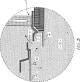
その後、作動装置が非作動化され、パドル60が図3の矢印50で示すように、その静止位置へ復帰し始める。
【0016】
ノズルチャンバの壁構造物11が一連のリム3と4を備えているので、インク供給チャネル52へのインクの逆流が妨げられる。これは、矢印9で示すように、ノズルチャンバへのインクの前方への流れを容易にし、射出後のインクを補充する。また、矢印9の方向にインクの前方への流れを更に助けるために、後述する制御方法でパドル60が復帰される。
【0017】
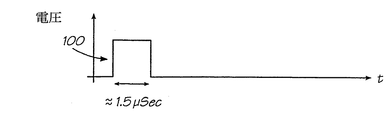
図4は、作動装置10を通して電流を駆動するために使用される電圧パルスの波形を示している。本出願人が2000年2月11日に出願した国際特許出願番号PCT/AU00/00095に記載されているように、電流が作動装置10の加熱と、その結果として作動装置10の曲げ変形を誘発して、パドル60を第1の位置から第2の位置へ移動させる。電圧と、その結果として、作動装置10を駆動するための図4に示すような電流パルス100とは、通常1.5μsecの期間印加される。作動装置の変位と、パドル移動とが、図5において参照符号12で示される最大レベルまで急激に上昇した後、電圧パルス期間終了に続いて、図5において参照符号13で示されるように、略同速度で降下する。第2の位置から第1の位置へ移動の際、パドル60の変位の平均速度は、第1の位置から第の2位置へのパドルの変位の平均速度に略等しい。
【0018】
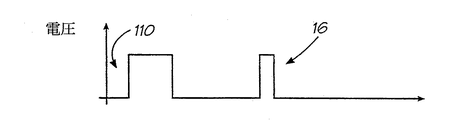
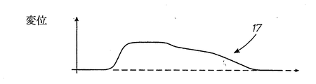
本発明の好適実施例では、作動装置10の変位の復帰速度、従ってパドルの移動も遅くなるが、これは作動装置10に一層短い持続期間の駆動電圧(及び電流)パルス16を印加することにより達成される。これは、パドル60に対する変位時間を延ばす、換言すれば、図7において参照符号17で示すように、第2位置から第1位置へのパドル60の復帰の平均速度を減少させる効果がある。
【0019】
図7に示す変位プロットは、比較的長いパルス110の発生に続いて、短い持続期間のパルス16を発生させることにより、特別な要求に応じるために更に延長することができる。
【0020】
パドルが静止する第1位置へのパドル60の緩やかな復帰は(第2位置に向かうパドル60の急速な動きに比較して)、ノズルチャンバへの増大したインクの流れを許容するが、これは入口チャネル52からチャンバ内へ流れるインクに対して、減少した背圧が加えられることから生じる。
【0021】
以上熱作動化される作動装置10を利用するインク射出システムについて本発明の実施例を説明したが、他のタイプの作動装置にも適用できる。例えば、熱作動装置の代替として、圧電式作動装置または形状記憶合金作動装置を使用してもよい。
【0022】
したがって、閉運動の間に変位時間を増大させ、その結果各々の方向への運動速度を変化させる目的で、上述したものとは異なる方法で作動装置を制御してもよい。
【0023】
特許請求の範囲において限定される発明の範囲から逸脱しなければ上述の例に変形及び変更を加えてもよい。
【図面の簡単な説明】
図1は、インクジェットプリンタのインク射出ノズルチャンバの一部を示す断面図である。
図1Aは、図1のノズルチャンバの一部を示す図であって、ノズルチャンバのパドルが静止した第1位置にある状態を示す。
図2は、図1のノズルチャンバの一部を示す図であって、ノズルチャンバのパドルが静止した第1位置に復帰した状態を示す。
図4は、ノズルチャンバのパドル作動装置に印加される駆動電圧の特性図である。
図5は、図4に示した駆動電圧の印加時間とパドル作動装置の変位の関係を示すグラフである。
図6は、本発明の好適形態によるパドル作動装置に印加される駆動電圧の特性図である。
図7は、図6に示した駆動電圧の印加時間とパドル作動装置の変位の関係を示すグラフである。[0001]
The present invention relates to a method for controlling an actuator in a microelectromechanical device. Although the invention will be described here with respect to an ink jet printer, the present invention can also be applied to other microelectromechanical devices such as microelectromechanical pumps.
[0002]
BACKGROUND OF THE INVENTION Microelectromechanical devices have become increasingly well known recently and are usually constructed using semiconductor assembly techniques.
[0003]
As a re-examination of micro-electromechanical devices, S. Announced on pages 24 to 33 of the IEEE Spectrum, published in December 1998. Tom Picraux and Paul Jay. You can consider the article “The Broad Sweep of Integrated Micro Systems” by Paul J. McWhorter.
[0004]
One type of micro electromechanical device is an ink jet printing device, and ink is ejected from the printing device by an ink ejection nozzle chamber. Many forms of ink jet printing apparatus are known. Research in this area includes "Output Hard Copy Devices", R.C. Dubeck and S.C. Edited by S. Sherr, 207-220 (1988), Jay. See J. Moore's article entitled “Non-Impact Printing: Introduction and Historical Perspective”.
[0005]
Recently, the Applicant has developed a new form of ink jet printing, referred to as Micro Electro Mechanical Inkjet (MEMJET) technology. In one embodiment of MEMJET technology, ink is ejected from the ink ejection nozzle chamber by a paddle or plunger that is moved by an electromechanical actuator toward the chamber ejection nozzle to eject a small amount of ink from the ink ejection nozzle chamber. It is injected.
[0006]
The present invention relates to thermal actuators used in MEMJET technology and in other microelectromechanical devices.
[0007]
SUMMARY OF THE INVENTION The present invention relates to a liquid flow for a liquid ejection device having a nozzle chamber, a liquid ejection port of the nozzle chamber, and a movable member located in the chamber for ejecting liquid through the ejection port, and the same Can be broadly defined as providing a method for controlling the liquid flow from In the method, the movable member moves at a first average speed from a first position where the movable member is stationary to a second position where the movable member is ejected, and is slower than the first average speed. The movable member is operated so that the movable member returns from the second position to the first position at an average speed.
[0008]
The movable member is preferably displaced from the first position to the second position by application of a primary excitation pulse and by application of at least one secondary excitation pulse having a shorter duration than that of the first excitation pulse. The displacement from the second position to the first position is delayed.
[0009]
Furthermore, the present invention ejects liquid from a nozzle chamber, a liquid ejection port of the nozzle chamber, a movable member located in the chamber for moving the liquid through the ejection port, and a first position stationary in the chamber. It can be broadly defined as providing a liquid ejection device with an actuating device in which the movable member is displaced to the second position. Further, after moving the movable member from the first position to the second position at the first average speed, the movable member from the second position to the first position at a second average speed that is slower than the first average speed. Means are also provided for controlling the actuation of the actuating device so as to be restored.
[0010]
The movable member in the liquid ejecting apparatus preferably includes a paddle, and when moved from the first position to the second position, opens a hole through which the liquid passes in order to perform the next ejection from the ejection port. Also preferably, the liquid ejection device includes a series of baffles adjacent to the holes to inhibit back flow of liquid through the holes while the paddle is moving from the second position to the first position.
[0011]
DESCRIPTION OF PREFERRED EMBODIMENTS Although the present invention belongs to the scope of other forms, the preferred embodiments of the present invention will now be described by way of example with reference to the accompanying drawings.
[0012]
FIG. 1 shows an ink ejection device 1. The apparatus 1 includes a
[0013]
FIG. 1A shows details of the apparatus shown in FIG. The
[0014]
Simultaneously with the actuation of the
[0015]
Thereafter, the actuator is deactivated and the
[0016]
Since the nozzle chamber wall structure 11 includes a series of rims 3 and 4, back flow of ink to the
[0017]
FIG. 4 shows the waveform of the voltage pulse used to drive current through the
[0018]
In the preferred embodiment of the present invention, the return speed of the displacement of the
[0019]
The displacement plot shown in FIG. 7 can be further extended to meet special requirements by generating a
[0020]
The slow return of the
[0021]
Although the embodiment of the present invention has been described with respect to the ink ejection system using the
[0022]
Therefore, the actuating device may be controlled in a different way than described above for the purpose of increasing the displacement time during the closing movement and consequently changing the speed of movement in each direction.
[0023]
Modifications and changes may be made to the above examples without departing from the scope of the invention as defined in the claims.
[Brief description of the drawings]
FIG. 1 is a cross-sectional view showing a part of an ink ejection nozzle chamber of an ink jet printer.
FIG. 1A is a view showing a part of the nozzle chamber of FIG. 1 and shows a state where the paddle of the nozzle chamber is in a stationary first position.
FIG. 2 is a view showing a part of the nozzle chamber of FIG. 1 and showing a state in which the paddle of the nozzle chamber is returned to the stationary first position.
FIG. 4 is a characteristic diagram of the drive voltage applied to the paddle actuator of the nozzle chamber.
FIG. 5 is a graph showing the relationship between the application time of the drive voltage shown in FIG. 4 and the displacement of the paddle actuator.
FIG. 6 is a characteristic diagram of the drive voltage applied to the paddle actuator according to the preferred embodiment of the present invention.
FIG. 7 is a graph showing the relationship between the application time of the drive voltage shown in FIG. 6 and the displacement of the paddle actuator.
Claims (6)
第1の平均速度で、前記パドルが静止する第1の位置から液体を射出する第2の位置へ前記パドルを動かすため、前記作動装置に対して第1の電圧パルスを供給するステップと、
前記第1の平均速度より遅い第2の平均速度で、前記第2の位置から前記第1の位置へ前記パドルを復帰させるため、前記作動装置に対して第2の電圧パルスを供給するステップと
を備えることを特徴とする方法。 A method of ejecting ink from a nozzle chamber by an ink ejecting apparatus, wherein the ink ejecting apparatus is connected to the paddle for moving the paddle, and can be bent and deformed by heat. In a method comprising
Supplying a first voltage pulse to the actuator to move the paddle from a first position where the paddle rests at a first average speed to a second position where liquid is ejected ;
In the first average speed slower second average speed, since from the second position attempting to bring the paddle to the first position, supplying a second voltage pulse to the actuator When
Method characterized in that comprises a.
ノズルチャンバと、
前記ノズルチャンバの表面により形成される液体射出口と、
前記液体射出口を通して液体を射出するため、前記チャンバ内に位置するパドルと、
前記チャンバ内に設けられ、前記パドルが静止する第1の位置から液体を射出する第2の位置へ前記パドルを動かすため前記パドルに接続され、かつ熱により曲げ変形可能な作動装置であって、自身に供給される電圧パルスに応じて曲げ変形する作動装置と、
前記作動装置の作動を制御する手段であって、第1の平均速度で前記第1の位置から前記第2の位置へ前記パドルを動かすため、前記作動装置に対して第1の電圧パルスを供給すると共に、前記第1の平均速度より遅い第2の平均速度で前記第2の位置から前記第1の位置へ前記パドルを復帰させるため、前記作動装置に対して第2の電圧パルスを供給する手段と
を備えることを特徴とする液体射出装置。 A liquid injection device,
A nozzle chamber;
A liquid injection port formed by the surface of the nozzle chamber;
A paddle located in the chamber for injecting liquid through the liquid outlet;
An actuator provided in the chamber , connected to the paddle for moving the paddle from a first position where the paddle rests to a second position for ejecting liquid , and bendable by heat ; An actuator that bends and deforms in response to voltage pulses supplied to it;
And means for controlling the operation of the actuating device, a first average speed dynamic said the paddle from the first position to the second position in Kasutame, a first voltage pulse to the actuator And supplying a second voltage pulse to the actuator for returning the paddle from the second position to the first position at a second average speed that is slower than the first average speed. A liquid ejecting apparatus.
Applications Claiming Priority (3)
| Application Number | Priority Date | Filing Date | Title |
|---|---|---|---|
| AU9930 | 1996-05-20 | ||
| AUPP9930A AUPP993099A0 (en) | 1999-04-22 | 1999-04-22 | A micromechancial device and method(ij46p2b) |
| PCT/AU2000/000339 WO2000064678A1 (en) | 1999-04-22 | 2000-04-20 | Actuator control in a micro electro-mechanical liquid ejection device |
Publications (2)
| Publication Number | Publication Date |
|---|---|
| JP2002542088A JP2002542088A (en) | 2002-12-10 |
| JP4476495B2 true JP4476495B2 (en) | 2010-06-09 |
Family
ID=3814129
Family Applications (2)
| Application Number | Title | Priority Date | Filing Date |
|---|---|---|---|
| JP2000613763A Pending JP2002542949A (en) | 1999-04-22 | 2000-04-20 | Actuator components |
| JP2000613652A Expired - Fee Related JP4476495B2 (en) | 1999-04-22 | 2000-04-20 | Control of actuator in liquid injection device of micro-electromechanical machine |
Family Applications Before (1)
| Application Number | Title | Priority Date | Filing Date |
|---|---|---|---|
| JP2000613763A Pending JP2002542949A (en) | 1999-04-22 | 2000-04-20 | Actuator components |
Country Status (12)
| Country | Link |
|---|---|
| US (1) | US6457795B1 (en) |
| EP (2) | EP1175371A4 (en) |
| JP (2) | JP2002542949A (en) |
| KR (2) | KR100597470B1 (en) |
| CN (3) | CN1242912C (en) |
| AT (1) | ATE369250T1 (en) |
| AU (1) | AUPP993099A0 (en) |
| CA (2) | CA2370773C (en) |
| DE (1) | DE60035869T2 (en) |
| IL (3) | IL145975A0 (en) |
| SG (1) | SG129258A1 (en) |
| WO (2) | WO2000064805A1 (en) |
Families Citing this family (20)
| Publication number | Priority date | Publication date | Assignee | Title |
|---|---|---|---|---|
| AU2004202250B2 (en) * | 1999-04-22 | 2006-08-10 | Silverbrook Research Pty Ltd | Long life actuator element |
| US6457812B1 (en) * | 2000-10-20 | 2002-10-01 | Silverbrook Research Pty Ltd | Bend actuator in an ink jet printhead |
| US7095309B1 (en) | 2000-10-20 | 2006-08-22 | Silverbrook Research Pty Ltd | Thermoelastic actuator design |
| AU2004233538B2 (en) * | 2000-10-20 | 2006-03-09 | Memjet Technology Limited | An inkjet nozzle structure having a structure for correcting the direction of ink ejection |
| AU2004202942B2 (en) * | 2000-10-20 | 2004-09-16 | Zamtec Limited | Method for operating nozzles in an ink jet printhead |
| US6561627B2 (en) * | 2000-11-30 | 2003-05-13 | Eastman Kodak Company | Thermal actuator |
| US6435666B1 (en) * | 2001-10-12 | 2002-08-20 | Eastman Kodak Company | Thermal actuator drop-on-demand apparatus and method with reduced energy |
| US6460972B1 (en) * | 2001-11-06 | 2002-10-08 | Eastman Kodak Company | Thermal actuator drop-on-demand apparatus and method for high frequency |
| US7052117B2 (en) | 2002-07-03 | 2006-05-30 | Dimatix, Inc. | Printhead having a thin pre-fired piezoelectric layer |
| US6896346B2 (en) * | 2002-12-26 | 2005-05-24 | Eastman Kodak Company | Thermo-mechanical actuator drop-on-demand apparatus and method with multiple drop volumes |
| US6848771B2 (en) * | 2003-06-30 | 2005-02-01 | Eastman Kodak Company | Method of operating a thermal actuator and liquid drop emitter with multiple pulses |
| US7281778B2 (en) | 2004-03-15 | 2007-10-16 | Fujifilm Dimatix, Inc. | High frequency droplet ejection device and method |
| US8491076B2 (en) | 2004-03-15 | 2013-07-23 | Fujifilm Dimatix, Inc. | Fluid droplet ejection devices and methods |
| KR20070087223A (en) | 2004-12-30 | 2007-08-27 | 후지필름 디마틱스, 인크. | Ink jet printing |
| JP4933629B2 (en) * | 2006-12-04 | 2012-05-16 | シルバーブルック リサーチ ピーティワイ リミテッド | Inkjet nozzle assembly having a thermal bending actuator that defines the main part of the nozzle chamber roof with an active beam |
| US7988247B2 (en) | 2007-01-11 | 2011-08-02 | Fujifilm Dimatix, Inc. | Ejection of drops having variable drop size from an ink jet printer |
| US8025367B2 (en) | 2008-10-17 | 2011-09-27 | Silverbrook Research Pty Ltd | Inkjet printhead with titanium aluminium alloy heater |
| EP2346693B1 (en) * | 2008-10-17 | 2014-05-07 | Zamtec Limited | Inkjet printhead with titanium aluminium alloy heater |
| CN107188113B (en) * | 2017-06-05 | 2019-03-12 | 东南大学 | A kind of nanometer displacement actuator |
| JP6999317B2 (en) * | 2017-07-21 | 2022-01-18 | 東芝テック株式会社 | Inkjet heads and inkjet printers |
Family Cites Families (15)
| Publication number | Priority date | Publication date | Assignee | Title |
|---|---|---|---|---|
| US3683212A (en) * | 1970-09-09 | 1972-08-08 | Clevite Corp | Pulsed droplet ejecting system |
| US3857049A (en) * | 1972-06-05 | 1974-12-24 | Gould Inc | Pulsed droplet ejecting system |
| US5231306A (en) * | 1992-01-31 | 1993-07-27 | Micron Technology, Inc. | Titanium/aluminum/nitrogen material for semiconductor devices |
| JPH063369A (en) * | 1992-04-20 | 1994-01-11 | Fujitsu Ltd | Accelerometer |
| JPH07310170A (en) * | 1994-05-13 | 1995-11-28 | Kobe Steel Ltd | Hard film excellent in oxidation resistance and wear resistance |
| US5652671A (en) * | 1994-06-30 | 1997-07-29 | Texas Instruments Incorporated | Hinge for micro-mechanical device |
| JPH08169110A (en) * | 1994-12-20 | 1996-07-02 | Sharp Corp | Ink jet head |
| US6000785A (en) * | 1995-04-20 | 1999-12-14 | Seiko Epson Corporation | Ink jet head, a printing apparatus using the ink jet head, and a control method therefor |
| SG79917A1 (en) * | 1995-04-26 | 2001-04-17 | Canon Kk | Liquid ejecting method with movable member |
| CA2184529A1 (en) * | 1995-09-01 | 1997-03-02 | John H. Tregilgas | Elastic member for micromechanical device |
| US5942054A (en) * | 1995-12-22 | 1999-08-24 | Texas Instruments Incorporated | Micromechanical device with reduced load relaxation |
| JP3045117B2 (en) * | 1996-10-14 | 2000-05-29 | ソニー株式会社 | Printer device |
| WO1999003681A1 (en) * | 1997-07-15 | 1999-01-28 | Silverbrook Research Pty. Limited | A thermally actuated ink jet |
| JP4170582B2 (en) * | 1997-07-15 | 2008-10-22 | シルバーブルック リサーチ プロプライエタリイ、リミテッド | Inkjet printing nozzle device |
| JP3857805B2 (en) * | 1997-12-10 | 2006-12-13 | ブラザー工業株式会社 | Ink droplet ejection method and apparatus |
-
1999
- 1999-04-22 AU AUPP9930A patent/AUPP993099A0/en not_active Abandoned
-
2000
- 2000-04-20 EP EP00920259A patent/EP1175371A4/en not_active Withdrawn
- 2000-04-20 CA CA002370773A patent/CA2370773C/en not_active Expired - Fee Related
- 2000-04-20 WO PCT/AU2000/000341 patent/WO2000064805A1/en active IP Right Grant
- 2000-04-20 SG SG200305581A patent/SG129258A1/en unknown
- 2000-04-20 CN CNB008063664A patent/CN1242912C/en not_active Expired - Fee Related
- 2000-04-20 JP JP2000613763A patent/JP2002542949A/en active Pending
- 2000-04-20 CN CNB2004100737993A patent/CN1318215C/en not_active Expired - Fee Related
- 2000-04-20 EP EP00920257A patent/EP1178888B1/en not_active Expired - Lifetime
- 2000-04-20 AT AT00920257T patent/ATE369250T1/en not_active IP Right Cessation
- 2000-04-20 JP JP2000613652A patent/JP4476495B2/en not_active Expired - Fee Related
- 2000-04-20 DE DE60035869T patent/DE60035869T2/en not_active Expired - Lifetime
- 2000-04-20 CA CA002370950A patent/CA2370950C/en not_active Expired - Fee Related
- 2000-04-20 IL IL14597500A patent/IL145975A0/en not_active IP Right Cessation
- 2000-04-20 KR KR1020017013425A patent/KR100597470B1/en not_active IP Right Cessation
- 2000-04-20 CN CNB008064040A patent/CN1172799C/en not_active Expired - Fee Related
- 2000-04-20 WO PCT/AU2000/000339 patent/WO2000064678A1/en active IP Right Grant
- 2000-04-20 KR KR1020017013427A patent/KR100639316B1/en not_active IP Right Cessation
- 2000-04-20 IL IL14597300A patent/IL145973A/en not_active IP Right Cessation
- 2000-04-24 US US09/556,217 patent/US6457795B1/en not_active Expired - Fee Related
-
2005
- 2005-04-26 IL IL168247A patent/IL168247A/en not_active IP Right Cessation
Also Published As
| Publication number | Publication date |
|---|---|
| CN1347369A (en) | 2002-05-01 |
| DE60035869D1 (en) | 2007-09-20 |
| SG129258A1 (en) | 2007-02-26 |
| CA2370950C (en) | 2008-11-18 |
| CA2370773C (en) | 2008-09-02 |
| IL145975A0 (en) | 2002-07-25 |
| EP1175371A4 (en) | 2004-06-16 |
| IL168247A (en) | 2011-11-30 |
| JP2002542949A (en) | 2002-12-17 |
| JP2002542088A (en) | 2002-12-10 |
| EP1175371A1 (en) | 2002-01-30 |
| IL145973A (en) | 2005-09-25 |
| EP1178888B1 (en) | 2007-08-08 |
| AUPP993099A0 (en) | 1999-05-20 |
| DE60035869T2 (en) | 2008-04-24 |
| WO2000064678A1 (en) | 2000-11-02 |
| CN1618612A (en) | 2005-05-25 |
| CN1242912C (en) | 2006-02-22 |
| EP1178888A1 (en) | 2002-02-13 |
| WO2000064805A1 (en) | 2000-11-02 |
| KR100639316B1 (en) | 2006-10-26 |
| IL145973A0 (en) | 2002-07-25 |
| US6457795B1 (en) | 2002-10-01 |
| EP1178888A4 (en) | 2002-07-17 |
| CN1172799C (en) | 2004-10-27 |
| KR100597470B1 (en) | 2006-07-05 |
| CA2370950A1 (en) | 2000-11-02 |
| KR20020012179A (en) | 2002-02-15 |
| CA2370773A1 (en) | 2000-11-02 |
| CN1347386A (en) | 2002-05-01 |
| CN1318215C (en) | 2007-05-30 |
| ATE369250T1 (en) | 2007-08-15 |
| KR20020012177A (en) | 2002-02-15 |
Similar Documents
| Publication | Publication Date | Title |
|---|---|---|
| JP4476495B2 (en) | Control of actuator in liquid injection device of micro-electromechanical machine | |
| JP3418185B2 (en) | Operation method of droplet deposit device | |
| US6276782B1 (en) | Assisted drop-on-demand inkjet printer | |
| JP4664092B2 (en) | Inkjet printhead driving method | |
| JP3920596B2 (en) | Inkjet recording apparatus and inkjet recording method | |
| JP5700989B2 (en) | Method for driving liquid discharge head and liquid discharge apparatus | |
| US20030063160A1 (en) | Variable size inlets in inkjet printhead | |
| EP1274584B1 (en) | Ink jet ejector | |
| US6488361B2 (en) | Inkjet printhead that incorporates closure mechanisms | |
| AU2004202252B2 (en) | Liquid ejection using a micro-electromechanical device | |
| AU770756B2 (en) | Actuator control in a micro electro-mechanical liquid ejection device | |
| JPS63139749A (en) | Ink jet recording head | |
| US6425654B1 (en) | Ink jet print head with tapered nozzle chambers | |
| JP2624772B2 (en) | Inkjet recording method | |
| EP1177900B1 (en) | Liquid discharging head, method for manufacturing liquid discharging head, and liquid discharging apparatus | |
| JP5362832B2 (en) | High efficiency inkjet nozzle assembly | |
| JP3529226B2 (en) | Inkjet printer | |
| US6447100B2 (en) | Nozzle arrangement for an ink jet printhead which includes a refill actuator | |
| JPH06179262A (en) | Printing head of ink-jet printer | |
| JP2000094670A (en) | Method for driving ink-jet head | |
| JP2001253071A (en) | Ink jet printer head and method of controlling the same | |
| JP2001315331A (en) | Ink jet recording method | |
| JPH10202895A (en) | Ink jet recorder |
Legal Events
| Date | Code | Title | Description |
|---|---|---|---|
| A621 | Written request for application examination |
Free format text: JAPANESE INTERMEDIATE CODE: A621 Effective date: 20070306 |
|
| RD03 | Notification of appointment of power of attorney |
Free format text: JAPANESE INTERMEDIATE CODE: A7423 Effective date: 20090430 |
|
| RD04 | Notification of resignation of power of attorney |
Free format text: JAPANESE INTERMEDIATE CODE: A7424 Effective date: 20090513 |
|
| A131 | Notification of reasons for refusal |
Free format text: JAPANESE INTERMEDIATE CODE: A131 Effective date: 20090901 |
|
| A601 | Written request for extension of time |
Free format text: JAPANESE INTERMEDIATE CODE: A601 Effective date: 20091201 |
|
| A602 | Written permission of extension of time |
Free format text: JAPANESE INTERMEDIATE CODE: A602 Effective date: 20091208 |
|
| A521 | Request for written amendment filed |
Free format text: JAPANESE INTERMEDIATE CODE: A523 Effective date: 20091224 |
|
| TRDD | Decision of grant or rejection written | ||
| A01 | Written decision to grant a patent or to grant a registration (utility model) |
Free format text: JAPANESE INTERMEDIATE CODE: A01 Effective date: 20100302 |
|
| A01 | Written decision to grant a patent or to grant a registration (utility model) |
Free format text: JAPANESE INTERMEDIATE CODE: A01 |
|
| A61 | First payment of annual fees (during grant procedure) |
Free format text: JAPANESE INTERMEDIATE CODE: A61 Effective date: 20100310 |
|
| R150 | Certificate of patent or registration of utility model |
Ref document number: 4476495 Country of ref document: JP Free format text: JAPANESE INTERMEDIATE CODE: R150 Free format text: JAPANESE INTERMEDIATE CODE: R150 |
|
| FPAY | Renewal fee payment (event date is renewal date of database) |
Free format text: PAYMENT UNTIL: 20130319 Year of fee payment: 3 |
|
| FPAY | Renewal fee payment (event date is renewal date of database) |
Free format text: PAYMENT UNTIL: 20130319 Year of fee payment: 3 |
|
| FPAY | Renewal fee payment (event date is renewal date of database) |
Free format text: PAYMENT UNTIL: 20140319 Year of fee payment: 4 |
|
| R250 | Receipt of annual fees |
Free format text: JAPANESE INTERMEDIATE CODE: R250 |
|
| R350 | Written notification of registration of transfer |
Free format text: JAPANESE INTERMEDIATE CODE: R350 |
|
| R250 | Receipt of annual fees |
Free format text: JAPANESE INTERMEDIATE CODE: R250 |
|
| R350 | Written notification of registration of transfer |
Free format text: JAPANESE INTERMEDIATE CODE: R350 |
|
| R250 | Receipt of annual fees |
Free format text: JAPANESE INTERMEDIATE CODE: R250 |
|
| R250 | Receipt of annual fees |
Free format text: JAPANESE INTERMEDIATE CODE: R250 |
|
| R250 | Receipt of annual fees |
Free format text: JAPANESE INTERMEDIATE CODE: R250 |
|
| R250 | Receipt of annual fees |
Free format text: JAPANESE INTERMEDIATE CODE: R250 |
|
| LAPS | Cancellation because of no payment of annual fees |