JP4476049B2 - Brushless motor control device - Google Patents
Brushless motor control device Download PDFInfo
- Publication number
- JP4476049B2 JP4476049B2 JP2004194390A JP2004194390A JP4476049B2 JP 4476049 B2 JP4476049 B2 JP 4476049B2 JP 2004194390 A JP2004194390 A JP 2004194390A JP 2004194390 A JP2004194390 A JP 2004194390A JP 4476049 B2 JP4476049 B2 JP 4476049B2
- Authority
- JP
- Japan
- Prior art keywords
- value
- boost
- control
- motor
- magnetic flux
- Prior art date
- Legal status (The legal status is an assumption and is not a legal conclusion. Google has not performed a legal analysis and makes no representation as to the accuracy of the status listed.)
- Expired - Fee Related
Links
Images
Landscapes
- Control Of Ac Motors In General (AREA)
- Control Of Motors That Do Not Use Commutators (AREA)
Description
本発明は、昇圧回路と、該昇圧回路の出力電圧を交流に変換してブラシレスモータに供給するインバータとを具えたブラシレスモータの制御装置に関するものである。 The present invention relates to a brushless motor control device including a booster circuit and an inverter that converts an output voltage of the booster circuit into an alternating current and supplies the same to a brushless motor.
従来、ブラシレスモータの最大回転数を増大させるべく、昇圧回路を具えて昇圧制御を行なうと共にモータに発生する磁束を減少させる弱め界磁制御を行なうモータ制御装置が知られている(例えば、特許文献1参照)。
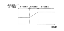
この種のモータ制御装置は、図12に示す如く、先ず、昇圧制御及び弱め界磁制御を行なうことなくPWM制御を行なう第1制御動作を実行し、その後、モータの回転数が所定の回転数に達した時点で、昇圧制御を行なう第2制御動作を開始する。更に、昇圧回路の昇圧比が上限値に達した時点で、昇圧制御及び弱め界磁制御を行なう第3制御動作を開始する。
この様に、昇圧制御及び弱め界磁制御を行なうことによって、モータの最大回転数を増大させることが出来る。
As shown in FIG. 12, this type of motor control device first executes a first control operation in which PWM control is performed without performing step-up control and field weakening control, and then the rotational speed of the motor reaches a predetermined rotational speed. At this point, the second control operation for performing boost control is started. Furthermore, when the boost ratio of the booster circuit reaches the upper limit value, a third control operation for performing boost control and field weakening control is started.
In this way, the maximum number of revolutions of the motor can be increased by performing boost control and field weakening control.
しかしながら、出願人の研究によれば、上記従来のモータ制御装置においては、昇圧回路の温度上昇が大きくなる場合があることが判明した。
そこで本発明の目的は、昇圧回路の温度上昇が大きくなることを防止することが出来るブラシレスモータの制御装置を提供することである。
However, according to the applicant's research, it has been found that in the conventional motor control device, the temperature rise of the booster circuit may be large.
Accordingly, an object of the present invention is to provide a brushless motor control device capable of preventing an increase in temperature of a booster circuit.
出願人は、昇圧回路の温度上昇が大きくなる原因を次のように究明した。
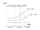
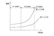
図13は、モータの駆動時に生じる損失の大きさの変化を表わしている。図示の如く、モータに発生するトルクが大きい高トルク時及び該トルクが小さい低トルク時の何れにおいても、損失は、モータの回転数が小さいときには緩やかに増大し、モータの回転数が増大すると急激に増大しているが、高トルク時には、低トルク時に比べて小さな回転数で損失が急激に増大している。
従来のモータ制御装置においては、昇圧比の上限値は、低トルク時に損失が急激に増大することとなる時点での大きな値に設定されているため、低トルク時には、損失が急激に増大する時点で弱め磁束制御が開始されて昇圧回路の温度上昇が小さな値に抑えられるものの、高トルク時には、損失が急激に増大した後に弱め磁束制御が開始されることとなって昇圧回路の温度上昇が大きくなる。
The applicant has investigated the cause of the increase in the temperature of the booster circuit as follows.
FIG. 13 shows a change in the magnitude of loss that occurs when the motor is driven. As shown in the figure, the loss increases slowly when the motor rotation speed is small, and increases rapidly when the motor rotation speed increases. However, when the torque is high, the loss rapidly increases at a smaller rotational speed than when the torque is low.
In the conventional motor control device, the upper limit value of the step-up ratio is set to a large value at the time when the loss suddenly increases at low torque, so the point at which the loss increases rapidly at low torque Although the magnetic flux weakening control is started and the temperature rise of the booster circuit is suppressed to a small value, at high torque, the magnetic flux weakening control is started after the loss increases rapidly, and the temperature rise of the booster circuit is large. Become.
本発明に係るブラシレスモータの制御装置は、直流の入力電圧を昇圧する昇圧回路と、昇圧回路の出力電圧を交流に変換してブラシレスモータに供給するインバータと、昇圧回路の昇圧比及びインバータの動作を制御する制御回路とを具え、該制御回路は、昇圧回路の昇圧比を1よりも大きな値に設定する昇圧制御動作を開始した後、ブラシレスモータから発生する磁束を減少させるための動作をインバータに実行させる磁束制御動作を開始するものである。そして、その特徴的構成において、該制御回路は、ブラシレスモータに発生するトルクの大きさに応じて、磁束制御動作を開始する時点を変化させる。 A brushless motor control device according to the present invention includes a booster circuit that boosts a DC input voltage, an inverter that converts an output voltage of the booster circuit into AC and supplies the brushless motor, a boost ratio of the booster circuit, and an operation of the inverter And a control circuit that controls the operation of the booster circuit after the boost control operation for setting the boost ratio of the booster circuit to a value larger than 1 is started, and an operation for reducing the magnetic flux generated from the brushless motor The magnetic flux control operation to be executed is started. In the characteristic configuration, the control circuit changes the time point at which the magnetic flux control operation is started in accordance with the magnitude of the torque generated in the brushless motor.
上記本発明に係るブラシレスモータの制御装置においては、ブラシレスモータに発生するトルクが大きい程、モータの回転数が小さい時点で磁束制御動作が開始される。これによって、高トルク時に、昇圧回路での損失の増大を抑えて、昇圧回路の温度上昇が大きくなることを防止することが出来る。 In the brushless motor control apparatus according to the present invention described above, the magnetic flux control operation is started when the motor rotation speed is smaller as the torque generated in the brushless motor is larger. As a result, at the time of high torque, it is possible to suppress an increase in loss in the booster circuit and to prevent an increase in temperature of the booster circuit.
第1の具体的構成において、前記制御回路は、ブラシレスモータを流れるモータ電流の大きさ或いは該モータ電流の大きさに応じた値から昇圧比或いは昇圧回路の出力電圧の上限値を導出し、昇圧比或いは昇圧回路の出力電圧がその上限値を超えた時点で磁束制御動作を開始する。該制御回路は、
外部から供給される昇圧指令値に基づいて昇圧制御動作を実行する昇圧制御手段と、
ブラシレスモータに対する印加電圧の大きさと、外部から供給されるモータ印加電圧制限値とを比較し、その比較結果に基づいて磁束制御動作を開始する磁束制御手段と、
昇圧指令値を前記昇圧制御手段に供給すると共に、モータ印加電圧制限値を前記磁束制御手段に供給する値供給手段
とを具え、該値供給手段は、
モータ電流の大きさ或いは該モータ電流の大きさに応じた値と昇圧比或いは昇圧回路の出力電圧の上限値との関係が規定されている第1関係規定手段と、
第1関係規定手段に規定されている関係に従って、モータ電流の大きさ或いは該モータ電流の大きさに応じた値から昇圧比或いは昇圧回路の出力電圧の上限値を導出する手段と、
昇圧比或いは昇圧回路の出力電圧の目標値が導出された上限値以下である場合には、該目標値を昇圧指令値として昇圧制御手段に供給する一方、該目標値が導出された上限値を上回る場合には、該上限値を昇圧指令値として昇圧制御手段に供給する手段と、
昇圧指令値とモータ印加電圧制限値の関係が規定されている第2関係規定手段と、
第2関係規定手段に規定されている関係に従って、昇圧制御手段に供給する昇圧指令値からモータ印加電圧制限値を導出して、磁束制御手段に供給する手段
とを具えている。
In the first specific configuration, the control circuit derives the boost ratio or the upper limit value of the output voltage of the booster circuit from the magnitude of the motor current flowing through the brushless motor or a value corresponding to the magnitude of the motor current, The magnetic flux control operation is started when the ratio or the output voltage of the booster circuit exceeds the upper limit. The control circuit
A boost control means for executing a boost control operation based on a boost command value supplied from the outside;
Magnetic flux control means for comparing the magnitude of the applied voltage to the brushless motor and the motor applied voltage limit value supplied from the outside, and starting the magnetic flux control operation based on the comparison result;
A value supply means for supplying a boost command value to the boost control means and supplying a motor applied voltage limit value to the magnetic flux control means, the value supply means,
A first relationship defining means for defining a relationship between the magnitude of the motor current or a value corresponding to the magnitude of the motor current and the boost ratio or the upper limit value of the output voltage of the booster circuit;
Means for deriving the step-up ratio or the upper limit value of the output voltage of the step-up circuit from the magnitude of the motor current or a value corresponding to the magnitude of the motor current in accordance with the relation prescribed in the first relation defining means;
When the target value of the boost ratio or the output voltage of the booster circuit is less than or equal to the derived upper limit value, the target value is supplied as a boost command value to the boost control means, while the upper limit value from which the target value is derived is When exceeding, means for supplying the upper limit value to the boost control means as a boost command value;
A second relationship defining means for defining a relationship between the boost command value and the motor applied voltage limit value;
Means for deriving a motor applied voltage limit value from the boost command value supplied to the boost control means in accordance with the relationship defined in the second relationship defining means, and supplying it to the magnetic flux control means.
ブラシレスモータを流れるモータ電流は、該モータに発生するトルクが増大するにつれて増大し、モータ電流とトルクとの間には比例関係が成立する。又、昇圧回路の温度は、モータ電流が増大するにつれて増大し、昇圧回路の温度とモータ電流との間には相関関係があるため、昇圧回路の温度とトルクとの間には相関関係がある。
そこで、上記具体的構成においては、ブラシレスモータを流れるモータ電流の大きさ或いはモータ電流の大きさに応じた値、例えば昇圧回路の温度から、トルクの大きさに応じた、昇圧比或いは昇圧回路の出力電圧の上限値が導出される。
そして、昇圧比或いは昇圧回路の出力電圧の目標値が該上限値以下である場合には、該目標値が昇圧指令値として昇圧制御手段に供給されると共に、該指令値に応じたモータ印加電圧制限値が導出されて磁束制御手段に供給される。これに対し、昇圧比或いは昇圧回路の出力電圧の目標値が前記上限値を上回っている場合には、該上限値が昇圧指令値として昇圧制御手段に供給されると共に、該指令値に応じたモータ印加電圧制限値が導出されて磁束制御手段に供給される。
昇圧制御手段では、上述の如く供給される昇圧指令値に基づいて昇圧制御動作が実行される。ここで、昇圧指令値は、昇圧比或いは昇圧回路の出力電圧の目標値が増大するにつれて増大し、該目標値が前記上限値に達した後、一定となる。従って、昇圧回路の出力電圧は、昇圧比或いは昇圧回路の出力電圧が前記上限値に達するまで徐々に増大し、その後、一定となる。
一方、磁束制御手段では、モータ印加電圧の大きさと上述の如く供給されるモータ印加電圧制限値とが比較され、その比較結果に基づいて磁束制御動作が開始される。ここで、上述の如く、昇圧比或いは昇圧回路の出力電圧の上限値はトルクの大きさに応じた値であり、昇圧比或いは昇圧回路の目標値が該上限値を上回っている場合には、該上限値に応じたモータ印加電圧制限値が磁束制御手段に供給されるので、磁束制御動作が開始される時点はトルクの大きさによって異なることになる。
The motor current flowing through the brushless motor increases as the torque generated in the motor increases, and a proportional relationship is established between the motor current and the torque. Further, the temperature of the booster circuit increases as the motor current increases, and there is a correlation between the temperature of the booster circuit and the motor current, so there is a correlation between the temperature of the booster circuit and the torque. .
Therefore, in the above specific configuration, the magnitude of the motor current flowing through the brushless motor or a value corresponding to the magnitude of the motor current, for example, the temperature of the booster circuit, the boost ratio or the booster circuit according to the magnitude of the torque. An upper limit value of the output voltage is derived.
When the target value of the boost ratio or the output voltage of the booster circuit is less than or equal to the upper limit value, the target value is supplied as a boost command value to the boost control means, and the motor applied voltage according to the command value A limit value is derived and supplied to the magnetic flux control means. On the other hand, when the boost ratio or the target value of the output voltage of the booster circuit exceeds the upper limit value, the upper limit value is supplied to the boost control means as a boost command value, and in accordance with the command value. A motor applied voltage limit value is derived and supplied to the magnetic flux control means.
In the boost control means, the boost control operation is executed based on the boost command value supplied as described above. Here, the boost command value increases as the target value of the boost ratio or the output voltage of the booster circuit increases, and becomes constant after the target value reaches the upper limit value. Accordingly, the output voltage of the booster circuit gradually increases until the boost ratio or the output voltage of the booster circuit reaches the upper limit value, and then becomes constant.
On the other hand, in the magnetic flux control means, the magnitude of the motor applied voltage is compared with the motor applied voltage limit value supplied as described above, and the magnetic flux control operation is started based on the comparison result. Here, as described above, the upper limit value of the boost ratio or the output voltage of the booster circuit is a value corresponding to the magnitude of the torque, and when the boost ratio or the target value of the booster circuit exceeds the upper limit value, Since the motor applied voltage limit value corresponding to the upper limit value is supplied to the magnetic flux control means, the time point at which the magnetic flux control operation is started varies depending on the magnitude of the torque.
第2の具体的構成において、前記制御回路は、昇圧制御と磁束制御の割合を変えることが可能であって、ブラシレスモータを流れるモータ電流の大きさ或いは該モータ電流の大きさに応じた値から、昇圧制御と磁束制御の割合を決めることとなる係数を導出し、導出された係数に応じて昇圧制御動作及び磁束制御動作を実行する。該制御回路は、
外部から供給される昇圧指令値に基づいて昇圧制御動作を実行する昇圧制御手段と、
ブラシレスモータに対する印加電圧の大きさと、外部から供給されるモータ印加電圧制限値とを比較し、その比較結果に基づいて磁束制御動作を開始すると共に、該モータ印加電圧制限値に基づいて磁束制御動作を実行する磁束制御手段と、
昇圧指令値を前記昇圧制御手段に供給すると共に、モータ印加電圧制限値を前記磁束制御手段に供給する値供給手段
とを具え、該値供給手段は、
モータ電流の大きさ或いは該モータ電流の大きさに応じた値と前記係数との関係が規定されている第1関係規定手段と、
第1関係規定手段に規定されている関係に従って、モータ電流の大きさ或いは該モータ電流の大きさに応じた値から前記係数を導出する手段と、
昇圧比或いは昇圧回路の出力電圧の目標値に対し導出された係数を用いた演算処理を施して昇圧指令値を算出する手段と、
算出された昇圧指令値を昇圧制御手段に供給する手段と、
昇圧指令値とモータ印加電圧制限値の関係が規定されている第2関係規定手段と、
第2関係規定手段に規定されている関係に従って、前記算出された昇圧指令値からモータ印加電圧制限値を導出して、磁束制御手段に供給する手段
とを具えている。
In the second specific configuration, the control circuit can change the ratio between the step-up control and the magnetic flux control, from the magnitude of the motor current flowing through the brushless motor or a value corresponding to the magnitude of the motor current. Then, a coefficient that determines the ratio between the boost control and the magnetic flux control is derived, and the boost control operation and the magnetic flux control operation are executed according to the derived coefficient. The control circuit
A boost control means for executing a boost control operation based on a boost command value supplied from the outside;
The magnitude of the voltage applied to the brushless motor is compared with the motor applied voltage limit value supplied from the outside, and the magnetic flux control operation is started based on the comparison result, and the magnetic flux control operation is performed based on the motor applied voltage limit value. Magnetic flux control means for executing
A value supply means for supplying a boost command value to the boost control means and supplying a motor applied voltage limit value to the magnetic flux control means, the value supply means,
A first relationship defining means in which a relationship between the magnitude of the motor current or a value corresponding to the magnitude of the motor current and the coefficient is defined;
Means for deriving the coefficient from the magnitude of the motor current or a value corresponding to the magnitude of the motor current according to the relation prescribed in the first relation defining means;
Means for calculating a boost command value by performing arithmetic processing using a coefficient derived for a boost ratio or a target value of the output voltage of the booster circuit;
Means for supplying the calculated boost command value to the boost control means;
A second relationship defining means for defining a relationship between the boost command value and the motor applied voltage limit value;
Means for deriving a motor applied voltage limit value from the calculated boost command value in accordance with the relationship defined in the second relationship defining means and supplying it to the magnetic flux control means.
上記具体的構成においては、ブラシレスモータを流れるモータ電流の大きさ、或いはモータ電流の大きさに応じた値、例えば昇圧回路の温度から、トルクの大きさに応じた係数が導出される。
そして、昇圧比或いは昇圧回路の出力電圧の目標値に対し前記導出された係数を用いた演算処理が施されて昇圧指令値が算出され、該指令値が昇圧制御手段に供給されると共に、該指令値に応じたモータ印加電圧制限値が導出されて磁束制御手段に供給される。
昇圧制御手段では、上述の如く供給される昇圧指令値に基づいて昇圧制御動作が実行される。ここで、昇圧指令値は、昇圧比或いは昇圧回路の出力電圧の目標値が増大するにつれて増大する。従って、昇圧回路の出力電圧は徐々に増大することになる。
一方、磁束制御手段では、モータ印加電圧の大きさと上述の如く供給されるモータ印加電圧制限値とが比較され、その比較結果に基づいて磁束制御動作が開始される。ここで、昇圧指令値は、上述の如く、トルクの大きさに応じた係数を用いた演算処理の実行によって得られる値であり、該昇圧指令値に応じたモータ印加電圧制限値が磁束制御手段に供給されるので、磁束制御動作が開始される時点はトルクの大きさによって異なることになる。その後、モータ印加電圧制限値に基づいて磁束制御動作が実行される。
上述の如く、トルクの大きさに応じた係数を用いた演算処理の実行によって得られる昇圧指令値に基づいて昇圧制御動作が実行されると共に、該昇圧指令値に応じたモータ印加電圧制限値に基づいて磁束制御動作が実行される。これによって、昇圧制御と磁束制御の割合がトルクの大きさに応じて変化することになる。
In the above specific configuration, a coefficient corresponding to the magnitude of the torque is derived from the magnitude of the motor current flowing through the brushless motor or a value corresponding to the magnitude of the motor current, for example, the temperature of the booster circuit.
Then, a calculation process using the derived coefficient is performed on the target value of the boost ratio or the output voltage of the booster circuit to calculate a boost command value, which is supplied to the boost control means, A motor application voltage limit value corresponding to the command value is derived and supplied to the magnetic flux control means.
In the boost control means, the boost control operation is executed based on the boost command value supplied as described above. Here, the boost command value increases as the boost ratio or the target value of the output voltage of the booster circuit increases. Accordingly, the output voltage of the booster circuit gradually increases.
On the other hand, in the magnetic flux control means, the magnitude of the motor applied voltage is compared with the motor applied voltage limit value supplied as described above, and the magnetic flux control operation is started based on the comparison result. Here, as described above, the boost command value is a value obtained by executing a calculation process using a coefficient corresponding to the magnitude of the torque, and the motor applied voltage limit value corresponding to the boost command value is the magnetic flux control means. Therefore, the point at which the magnetic flux control operation is started varies depending on the magnitude of the torque. Thereafter, the magnetic flux control operation is executed based on the motor applied voltage limit value.
As described above, the boost control operation is executed based on the boost command value obtained by executing the arithmetic processing using the coefficient corresponding to the magnitude of the torque, and the motor applied voltage limit value corresponding to the boost command value is set. Based on this, the magnetic flux control operation is executed. As a result, the ratio between the boost control and the magnetic flux control changes according to the magnitude of the torque.
具体的には、前記制御回路は、モータ電流の磁束方向成分の大きさを検出する電流検出手段を具え、前記磁束制御手段は、
値供給手段から供給されるモータ印加電圧制限値からモータ電流の磁束方向成分の大きさの目標値を表わす目標電流値を導出する手段と、
電流検出手段によって検出された電流値と導出された目標電流値とに基づき制御信号を作成してインバータに供給する手段
とを具えている。
Specifically, the control circuit includes current detection means for detecting the magnitude of the magnetic flux direction component of the motor current, and the magnetic flux control means includes:
Means for deriving a target current value representing a target value of the magnitude of the magnetic flux direction component of the motor current from the motor applied voltage limit value supplied from the value supply means;
Means for generating a control signal based on the current value detected by the current detection means and the derived target current value and supplying the control signal to the inverter.
上記具体的構成を有するモータ制御装置は、ブラシレスモータに発生する磁束の方向とは逆方向に電流を流すことによって該磁束を減少させる弱め磁束制御を行なうものであって、磁束制御手段は、電流検出手段によって検出された電流値とモータ印加電圧制限値から導出された目標電流値とに基づいて制御信号を作成する。これによって、モータ電流の磁束方向成分を目標電流値に追従させるための制御信号が作成されて、モータ電流の磁束方向成分の大きさが制御される。 The motor control device having the above specific configuration performs weak flux control by decreasing the magnetic flux by flowing a current in a direction opposite to the direction of the magnetic flux generated in the brushless motor. A control signal is created based on the current value detected by the detection means and the target current value derived from the motor applied voltage limit value. As a result, a control signal for causing the magnetic flux direction component of the motor current to follow the target current value is created, and the magnitude of the magnetic flux direction component of the motor current is controlled.
本発明に係るブラシレスモータの制御装置によれば、昇圧回路の温度上昇が大きくなることを防止することが出来る。 According to the brushless motor control device of the present invention, it is possible to prevent an increase in the temperature of the booster circuit.
以下、本発明の実施の形態につき、4つの実施例に基づいて具体的に説明する。
第1実施例
本実施例のブラシレスモータの制御装置は、昇圧制御を行なうことが可能であると共に、モータに発生する磁束の方向とは逆の方向に電流を流すことによって該磁束を減少させる弱め磁束制御を行なうことが可能である。そして、該制御装置は、モータの駆動時には、先ず、昇圧制御及び弱め磁束制御を行なうことなくPWM制御を行なう第1制御動作を実行し、その後、昇圧制御を行なう第2制御動作を実行し、更に、昇圧制御及び弱め磁束制御を行なう第3制御動作を実行する。
Hereinafter, embodiments of the present invention will be described in detail based on four examples.
First Embodiment The brushless motor control apparatus of the present embodiment is capable of performing step-up control, and is a weakening that reduces the magnetic flux by flowing a current in a direction opposite to the direction of the magnetic flux generated in the motor. Magnetic flux control can be performed. When the motor is driven, the control device first executes a first control operation for performing PWM control without performing boost control and flux-weakening control, and then executes a second control operation for performing boost control. Further, a third control operation for performing boost control and flux-weakening control is executed.
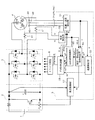
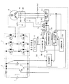
本実施例のブラシレスモータの制御装置は、図1に示す如く、直流電源(1)からの電圧を昇圧する昇圧回路(2)と、昇圧回路(2)の出力電圧を交流電圧に変換してブラシレスモータ(4)に供給するインバータ(3)と、昇圧回路(2)及びインバータ(3)の動作を制御する制御回路(5)と、該制御回路(5)からのPWM信号に基づいてインバータ(3)を駆動するドライブ回路(6)とを具えている。昇圧回路(2)は、スイッチング素子、コンデンサ、抵抗及びダイオードから構成されており、前記制御回路(5)によってスイッチング素子がオン/オフ制御される。又、インバータ(3)は、6つのスイッチング素子と、これらのスイッチング素子にそれぞれ接続された6つのダイオードとから構成されており、前記制御回路(5)によって、これら6つのスイッチング素子がオン/オフ制御される。 As shown in FIG. 1, the brushless motor control apparatus of this embodiment converts a voltage from a DC power source (1) to a booster circuit (2) and converts the output voltage of the booster circuit (2) into an AC voltage. An inverter (3) supplied to the brushless motor (4), a control circuit (5) for controlling the operation of the booster circuit (2) and the inverter (3), and an inverter based on the PWM signal from the control circuit (5) And a drive circuit (6) for driving (3). The booster circuit (2) is composed of a switching element, a capacitor, a resistor, and a diode, and the switching element is on / off controlled by the control circuit (5). The inverter (3) is composed of six switching elements and six diodes respectively connected to these switching elements, and these six switching elements are turned on / off by the control circuit (5). Be controlled.
ブラシレスモータ(4)には、その回転軸を中心とする円周上に、ホール素子からなる位置センサ(40)が120度の位相差で3箇所に配備されており、これら3つの位置センサ(40)(40)(40)から得られる3つの位置信号(Hu,Hv,Hw)は、前記制御回路(5)の位置・速度検出部(51)に供給される。各位置信号は、図3(a)に示す如く、360度を1周期としてハイとローに切り替わる矩形波であって、3つの位置信号は互いに120度の位相差を有している。
又、ブラシレスモータ(4)は、固定子にu相巻線、v相巻線及びw相巻線を巻き付けて構成されており、該モータ(4)には、u相巻線及びv相巻線をそれぞれ流れる電流を検出する電流センサ(41)(41)が設けられている。これら2つの電流センサ(41)(41)から得られる2つの電流値iu、ivは、前記制御回路(5)の電流検出部(52)に供給される。
位置・速度検出部(51)では、3つの位置信号(Hu,Hv,Hw)に基づいてモータの回転数ωが検出され、その検出結果が、速度制御部(53)、昇圧・弱め磁束指令生成部(54)及びPWM制御部(56)に供給される。又、位置・速度検出部(51)では、3つの位置信号(Hu,Hv,Hw)と前記回転数ωとに基づいてモータの回転角度θが検出され、その検出結果が、電流検出部(52)及びPWM制御部(56)に供給される。
電流検出部(52)では、2つの電流値iu、ivと前記回転角度θとに基づいてモータに流れるモータ電流の磁束方向成分、即ちd軸方向成分idと、該磁束方向に直交する方向の成分、即ちq軸方向成分iqとが算出され、それらの算出結果が、昇圧・弱め磁束指令生成部(54)及びPWM制御部(56)に供給される。
In the brushless motor (4), position sensors (40) made up of Hall elements are arranged at three locations with a phase difference of 120 degrees on the circumference around the rotation axis, and these three position sensors ( The three position signals (Hu, Hv, Hw) obtained from (40), (40), and (40) are supplied to the position / velocity detecting section (51) of the control circuit (5). As shown in FIG. 3A, each position signal is a rectangular wave that switches between high and low with 360 degrees as one cycle, and the three position signals have a phase difference of 120 degrees.
The brushless motor (4) is constituted by winding a u-phase winding, a v-phase winding and a w-phase winding around a stator. The motor (4) includes a u-phase winding and a v-phase winding. Current sensors (41) and (41) for detecting currents flowing through the lines are provided. The two current values iu and iv obtained from these two current sensors (41) and (41) are supplied to the current detector (52) of the control circuit (5).
In the position / speed detection unit (51), the rotational speed ω of the motor is detected based on the three position signals (Hu, Hv, Hw), and the detection result is obtained as a result of the speed control unit (53), the step-up / weakening magnetic flux command. This is supplied to the generation unit (54) and the PWM control unit (56). The position / speed detector (51) detects the rotation angle θ of the motor based on the three position signals (Hu, Hv, Hw) and the rotational speed ω, and the detection result is obtained as a current detector ( 52) and the PWM control unit (56).
In the current detection unit (52), the magnetic flux direction component of the motor current flowing in the motor based on the two current values iu and iv and the rotation angle θ, that is, the d-axis direction component id and the direction perpendicular to the magnetic flux direction. The component, that is, the q-axis direction component iq is calculated, and the calculation result is supplied to the step-up / weakening magnetic flux command generation unit (54) and the PWM control unit (56).
速度制御部(53)では、前記回転数ωと目標回転数ω*とに基づいて、下記数1から、モータ電流のq軸方向成分の目標値iq*が算出され、回転数ωが目標回転数ω*に一致するようにPI制御される。
(数1)
iq*=(ksp+ksi/s)(ω*−ω)
ksp、ksi:定数
s:ラプラス演算子
上述の如く算出された目標q軸方向電流iq*は、昇圧・弱め磁束指令生成部(54)及びPWM制御部(56)に供給される。
In the speed control unit (53), the target value iq * of the q-axis direction component of the motor current is calculated from the following
(Equation 1)
iq * = ( ksp + ksi / s) (ω * −ω)
k sp , k si : Constant s: Laplace operator The target q-axis direction current iq * calculated as described above is supplied to the boosting / weakening magnetic flux command generation unit (54) and the PWM control unit (56).
昇圧・弱め磁束指令生成部(54)は、位置・速度検出部(51)から供給されるモータ回転数ωが所定の閾値以下である場合には、昇圧比の指令値αとして“1”の値を昇圧制御部(57)に供給すると共に、モータに対する印加電圧の制限値Vomとして所定値Vom0を弱め磁束制御部(55)に供給する。 The step-up / weakening magnetic flux command generation unit (54) sets “1” as the step-up ratio command value α when the motor rotational speed ω supplied from the position / velocity detection unit (51) is equal to or less than a predetermined threshold. It supplies the value to the boost control unit (57) to the magnetic flux controller (55) to weaken the predetermined value Vom 0 as the limit value Vom of voltage applied to the motor.
その後、位置・速度検出部(51)から供給されるモータ回転数ωが所定の閾値を超えると、昇圧・弱め磁束指令生成部(54)は、該モータ回転数ωに基づいて下記数2から昇圧比の目標値α*を算出する動作を開始する。尚、モータ回転数ωと昇圧比の目標値α*の関係を表わすテーブルを格納しておき、該テーブルを参照して、モータ回転数ωから昇圧比の目標値α*を導出する構成を採用することも可能である。
(数2)
α*=k・ω/ω0
k:定数
ω0:昇圧比が1であるときのモータ回転数の最大値
Thereafter, when the motor rotation speed ω supplied from the position / velocity detection section (51) exceeds a predetermined threshold value, the boosting / weakening magnetic flux command generation section (54) calculates the following expression 2 based on the motor rotation speed ω. The operation for calculating the target value α * of the boost ratio is started. A table representing the relationship between the motor rotational speed ω and the target value α * of the boost ratio is stored, and a configuration in which the target value α * of the boost ratio is derived from the motor rotational speed ω by referring to the table is adopted. It is also possible to do.
(Equation 2)
α * = k · ω / ω 0
k: Constant ω 0 : Maximum value of motor rotation speed when the step-up ratio is 1
そして、昇圧・弱め磁束指令生成部(54)は、昇圧比の目標値α*が後述の如く導出される上限値αmを超えているか否かを判断し、昇圧比の目標値α*が上限値αm以下である場合には、該目標値α*を昇圧指令値αとして昇圧制御部(57)に供給する。又、該昇圧指令値αに基づいて、下記数3からモータ印加電圧の制限値Vomを算出し、該制限値Vomを弱め磁束制御部(55)に供給する。
(数3)
Vom=α・Vom0
Vom0:昇圧比が1であるときのモータ印加電圧の制限値
Then, the boost-flux-weakening command generation unit (54) determines whether the target value of the boost ratio alpha * exceeds the upper limit value αm derived as described later, the target value alpha * is the upper limit of the step-up ratio When the value αm is equal to or less than the value αm, the target value α * is supplied to the boost control unit (57) as the boost command value α. Further, based on the boost command value α, the limit value Vom of the motor applied voltage is calculated from the following
(Equation 3)
Vom = α ・ Vom 0
Vom 0 : Limit value of motor applied voltage when the step-up ratio is 1
これに対し、昇圧比の目標値α*が上限値αmを超えている場合には、昇圧指令値として該上限値αmを昇圧制御部(57)に供給する。又、該上限値αmを昇圧指令値αとして、上記数3からモータ印加電圧の制限値Vomを算出し、該制限値Vomを弱め磁束制御部(55)に供給する。
On the other hand, when the target value α * of the boost ratio exceeds the upper limit value αm, the upper limit value αm is supplied to the boost control unit (57) as the boost command value. Further, the limit value Vom of the motor applied voltage is calculated from the
上述の上限値αmは、後述の如く導出される。
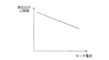
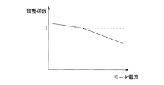
モータ電流のq軸方向成分iqは、モータに発生するトルクの大きさが増大するにつれて増大し、q軸方向電流iqとトルクとの間には比例関係が成立する。そこで、昇圧・弱め磁束指令生成部(54)には、q軸方向電流と昇圧比の上限値の図4に示す関係を表わすテーブルが格納されており、該テーブルを参照して、電流検出部(52)から供給されるq軸方向電流iqから昇圧比の上限値αmが導出される。q軸方向電流と昇圧比の上限値は、図示の如くq軸方向電流iqが増大するにつれて昇圧比の上限値αmは減小する関係を有しており、モータに発生するトルクが大きい程、小さな上限値αmが導出されることになる。
尚、モータ電流のq軸方向成分iqと昇圧比の上限値αmの比例関係を表わす関数式を格納しておき、該関数式を用いて昇圧比の上限値αmを算出する構成を採用することも可能である。
The above upper limit value αm is derived as described later.
The q-axis direction component iq of the motor current increases as the magnitude of torque generated in the motor increases, and a proportional relationship is established between the q-axis direction current iq and the torque. Therefore, a table representing the relationship shown in FIG. 4 between the current in the q-axis direction and the upper limit value of the step-up ratio is stored in the step-up / weakening magnetic flux command generation unit (54). The upper limit value αm of the step-up ratio is derived from the q-axis direction current iq supplied from (52). The upper limit value of the q-axis direction current and the step-up ratio have a relationship such that the upper limit value αm of the step-up ratio decreases as the q-axis direction current iq increases as shown in the figure. As the torque generated in the motor increases, A small upper limit value αm will be derived.
It is to be noted that a function formula representing a proportional relationship between the q-axis direction component iq of the motor current and the upper limit value αm of the boost ratio is stored, and a configuration for calculating the upper limit value αm of the boost ratio using the function formula is adopted. Is also possible.
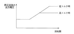
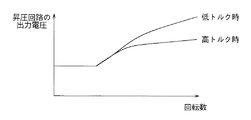
図1の昇圧制御部(57)では、昇圧・弱め磁束指令生成部(54)から供給される昇圧指令値αに基づき昇圧回路(2)のスイッチング素子に対するスイッチング信号が作成されて昇圧回路(2)に供給される。これによって、昇圧回路(2)の出力電圧は、図5に示す如く、モータの回転数ωが前記所定の閾値を超えるまでは、昇圧比が“1”に設定されて一定となり、モータの回転数ωが前記所定の閾値を超えると、該回転数ωが増大するにつれて昇圧比が徐々に大きな値に設定されて徐々に増大する。その後、昇圧比が上限値に達すると、昇圧回路(2)の出力電圧は一定となる。ここで、昇圧比の上限値は、上述の如くモータに発生するトルクが大きい程、小さな値に設定されるので、図示の如く、高トルク時における昇圧回路(2)の出力電圧は、低トルク時に比べて小さな回転数で一定値となる。 In the step-up control unit (57) in FIG. 1, a switching signal for the switching element of the step-up circuit (2) is created based on the step-up command value α supplied from the step-up / weakening magnetic flux command generation unit (54), and the step-up circuit (2 ). As a result, as shown in FIG. 5, the output voltage of the booster circuit (2) is kept constant by setting the boost ratio to “1” until the rotational speed ω of the motor exceeds the predetermined threshold value. When the number ω exceeds the predetermined threshold value, the step-up ratio is gradually set to a large value and gradually increases as the rotational speed ω increases. Thereafter, when the boost ratio reaches the upper limit value, the output voltage of the booster circuit (2) becomes constant. Here, since the upper limit value of the boost ratio is set to a smaller value as the torque generated in the motor is larger as described above, the output voltage of the booster circuit (2) at the time of high torque is low torque as shown in the figure. It becomes a constant value at a smaller rotational speed than sometimes.
図1の弱め磁束制御部(55)では、モータ印加電圧の振幅値Va(=√(Vd*2+Vq*2))が昇圧・弱め磁束指令生成部(54)から供給される制限値Vomを下回るか否かが判断され、モータ印加電圧の振幅値Vaが該制限値Vomを下回る場合には、モータ電流のd軸方向成分の目標値id*として、モータに発生するトルクが最大となる後述の値がPWM制御部(56)に供給される。
即ち、巻線のインダクタンスのd軸方向成分Ldとq軸方向成分Lqが同じ値である場合には、目標d軸方向電流id*として“0”の値がPWM制御部(56)に供給される。
一方、巻線のインダクタンスのd軸方向成分Ldとq軸方向成分Lqが異なる値である場合には、下記数4から、目標d軸方向電流id*が算出されてPWM制御部(56)に供給される。
(数4)
id*={φa/2・(Lq−Ld)}−√{φa2/4・(Lq−Ld)2+iq2}
φa:巻線の鎖交磁束数
In the magnetic flux weakening control unit (55) of FIG. 1, the amplitude value Va (= √ (Vd * 2 + Vq * 2 )) of the motor applied voltage is set to the limit value Vom supplied from the boosting / weakening magnetic flux command generation unit (54). If the motor applied voltage amplitude value Va falls below the limit value Vom, the torque generated in the motor is maximized as a target value id * of the d-axis direction component of the motor current, which will be described later. Is supplied to the PWM controller (56).
That is, when the d-axis direction component Ld and the q-axis direction component Lq of the winding inductance are the same value, a value of “0” is supplied to the PWM controller (56) as the target d-axis direction current id *. The
On the other hand, when the d-axis direction component Ld and the q-axis direction component Lq of the winding inductance are different from each other, the target d-axis direction current id * is calculated from the
(Equation 4)
id * = {φa / 2 · (Lq-Ld)} - √ {φa 2/4 · (Lq-Ld) 2 + iq 2}
φa: Number of flux linkages in winding
これに対し、前記振幅値Vaが前記制限値Vom以上である場合には、下記数5から、目標d軸方向電流id*が算出されてPWM制御部(56)に供給される。
(数5)
id*=[−φa+√{(Vom/ω)2−(Lq・iq)2}]/Ld
φa:巻線の鎖交磁束数
On the other hand, when the amplitude value Va is equal to or greater than the limit value Vom, the target d-axis direction current id * is calculated from the following
(Equation 5)
id * = [− φa + √ {(Vom / ω) 2 − (Lq · iq) 2 }] / Ld
φa: Number of flux linkages in winding
図2に示すPWM制御部(56)の電流制御部(561)では、電流検出部(52)から供給されるd軸方向電流idと弱め磁束制御部(55)から供給される目標d軸方向電流id*と位置・速度検出部(51)から供給されるモータ回転速度ωとに基づいて、下記数6から、モータ印加電圧のd軸方向成分の目標値Vd*が算出されると共に、電流検出部(52)から供給されるq軸方向電流iqと速度制御部(53)から供給される目標q軸方向電流iq*と位置・速度検出部(51)から供給されるモータ回転速度ωとに基づいて、下記数7から、モータ印加電圧のq軸方向成分の目標値Vq*が算出される。
In the current control unit (561) of the PWM control unit (56) shown in FIG. 2, the d-axis direction current id supplied from the current detection unit (52) and the target d-axis direction supplied from the flux weakening control unit (55). Based on the current id * and the motor rotation speed ω supplied from the position / speed detection unit (51), the target value Vd * of the d-axis direction component of the motor applied voltage is calculated from the
(数6)
Vd*=(kp+ki/s)・(id*−id)−ω・Lq・iq
kp、ki:定数
s:ラプラス演算子
(数7)
Vq*=(kp+ki/s)・(iq*−iq)+ω・(Ld・id+φa)
φa:巻線の鎖交磁束数
kp、ki:定数
s:ラプラス演算子
(Equation 6)
Vd * = (k p + k i / s) · (id * -id) -ω · Lq · iq
k p , k i : constant s: Laplace operator
(Equation 7)
Vq * = (k p + k i / s) · (iq * -iq) + ω · (Ld · id + φa)
φa: number of flux linkages k p , k i : constant s: Laplace operator
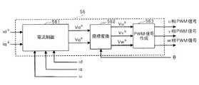
上述の如く算出された目標d軸方向電圧Vd*、及び目標q軸方向電圧Vq*は、座標変換部(562)に供給され、座標変換部(562)では、これらの電圧のそれぞれに対し、位置・速度検出部(51)から供給されるモータ回転角度θを用いた座標変換処理を施すことによって、ブラシレスモータのu相についての電圧指令信号Vu*、v相についての電圧指令信号Vv*、及びw相についての電圧指令信号Vw*が作成され、これら3相の電圧指令信号は、PWM信号作成部(563)に供給される。
PWM信号作成部(563)では、図3(b)に示す如く、u相の電圧指令信号Vu*と所定の搬送波(三角波)とが比較され、該比較結果に基づいて、同図(c)に示すu相の駆動信号(PWM信号)が作成される。同様にして、v相の電圧指令信号Vv*と所定の搬送波とが比較されてv相の駆動信号が作成され、w相の電圧指令信号Vw*と所定の搬送波とが比較されてw相の駆動信号が作成される。
The target d-axis direction voltage Vd * and the target q-axis direction voltage Vq * calculated as described above are supplied to the coordinate conversion unit (562), and the coordinate conversion unit (562) By performing a coordinate conversion process using the motor rotation angle θ supplied from the position / speed detector (51), the voltage command signal Vu * for the u phase of the brushless motor, the voltage command signal Vv * for the v phase, And the voltage command signal Vw * for the w-phase is generated, and these three-phase voltage command signals are supplied to the PWM signal generating unit (563).
In the PWM signal generator (563), as shown in FIG. 3 (b), the u-phase voltage command signal Vu * is compared with a predetermined carrier wave (triangular wave), and based on the comparison result, FIG. The u-phase drive signal (PWM signal) shown in FIG. Similarly, the v-phase voltage command signal Vv * and a predetermined carrier wave are compared to create a v-phase drive signal, and the w-phase voltage command signal Vw * and the predetermined carrier wave are compared to determine the w-phase drive signal. A drive signal is created.
この様にして作成されたu相、v相、w相のPWM信号は、図1に示すドライブ回路(6)に供給され、該ドライブ回路(6)では、これらのPWM信号に基づきインバータ(3)に対するドライブ信号が作成されてインバータ(3)に供給され、インバータ(3)が制御される。この結果、ブラシレスモータ(4)が駆動されることになる。 The u-phase, v-phase, and w-phase PWM signals created in this way are supplied to the drive circuit (6) shown in FIG. 1, and in the drive circuit (6), the inverter (3 ) Is generated and supplied to the inverter (3) to control the inverter (3). As a result, the brushless motor (4) is driven.
本実施例のモータ制御装置においては、上述の如く、モータに発生するトルクの大きさに応じた昇圧上限値αmが導出され、昇圧比の目標値α*が該上限値αmを超えている場合には、該上限値αmから上記数3を用いてモータ印加電圧の制限値Vomが算出される。従って、該制限値Vomは、トルクの大きさに応じた値となり、弱め磁束制御部(55)にてモータ印加電圧の振幅値Vaがモータ印加電圧の制限値Vom以上であると判断されて弱め磁束制御が開始される時点が、トルクの大きさに応じて変化することになる。即ち、高トルク時には、低トルク時に比べて小さな昇圧上限値αmが算出されて、小さな制限値Vomが算出される。従って、弱め磁束制御部(55)にてモータ印加電圧の振幅値Vaがモータ印加電圧の制限値Vom以上であると判断される時点が早くなり、低トルク時よりも低い回転数で弱め磁束制御が開始されることになる。 In the motor control device of the present embodiment, as described above, when the boost upper limit value αm corresponding to the magnitude of the torque generated in the motor is derived and the target value α * of the boost ratio exceeds the upper limit value αm In this case, the limit value Vom of the motor applied voltage is calculated from the upper limit value αm using the above equation (3). Therefore, the limit value Vom becomes a value according to the magnitude of the torque, and the weakening magnetic flux control unit (55) determines that the amplitude value Va of the motor applied voltage is greater than or equal to the limit value Vom of the motor applied voltage. The time point at which the magnetic flux control is started changes depending on the magnitude of the torque. That is, at the time of high torque, a smaller boost upper limit value αm is calculated than at the time of low torque, and a smaller limit value Vom is calculated. Therefore, the time point at which the amplitude value Va of the motor applied voltage is determined to be greater than or equal to the limit value Vom of the motor applied voltage by the field weakening magnetic flux control unit (55) is earlier, and the field weakening magnetic flux control is performed at a lower rotational speed than during low torque. Will be started.
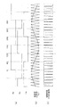
図6は、本実施例のモータ制御装置において制御動作が第1制御動作と第2制御動作と第3制御動作との間で切り替わるタイミングを表わしている。尚、図中の破線は、仮に制御動作を第2制御動作から第3制御動作に切り換えなかった場合の損失の変化を表わしている。
高トルク時には、昇圧比の上限値αmが低トルク時に比べて小さな値に設定されるので、図示の如く、低トルク時よりも小さな回転数で第2制御動作から第3制御動作に制御動作が切り替わることになる。
FIG. 6 shows the timing at which the control operation is switched among the first control operation, the second control operation, and the third control operation in the motor control device of this embodiment. The broken line in the figure represents a change in loss when the control operation is not switched from the second control operation to the third control operation.
At the time of high torque, the upper limit value αm of the step-up ratio is set to a smaller value than at the time of low torque, so that the control operation is changed from the second control operation to the third control operation at a lower rotational speed than at the time of low torque as shown in the figure. It will be switched.
本実施例のモータ制御装置においては、上述の如く、高トルク時には、低トルク時よりも小さな回転数で第3制御動作を開始することによって、昇圧回路での損失の増大を抑えて昇圧回路の温度上昇を抑制することが出来る。一方、低トルク時には、弱め磁束制御による損失の増大を抑えてモータの温度上昇を抑制することが出来る。 In the motor control device of the present embodiment, as described above, at the time of high torque, the third control operation is started at a lower rotation speed than at the time of low torque, thereby suppressing an increase in loss in the booster circuit. Temperature rise can be suppressed. On the other hand, at the time of low torque, it is possible to suppress an increase in loss due to the magnetic flux weakening control and suppress an increase in the temperature of the motor.
尚、上記実施例においては、モータ回転数ωから昇圧比の指令値αを算出しているが、モータ回転数ωが高くなるにつれてモータ印加電圧は高くなり、モータ回転数ωとモータ印加電圧との間には相関関係があるため、モータ印加電圧から昇圧比の指令値αを算出することも可能である。 In the above embodiment, the command value α for the step-up ratio is calculated from the motor rotational speed ω. However, as the motor rotational speed ω increases, the motor applied voltage increases, and the motor rotational speed ω, the motor applied voltage, Since there is a correlation, the step-up ratio command value α can be calculated from the motor applied voltage.
又、モータ電流のq軸方向成分iqは、下記数8によって表わされる。
(数8)
iq=η・Vdc・Idc/ω・Kt
η:モータ効率
Vdc:電源電圧
Idc:電源電流
Kt:トルク定数
電源電圧Vdc及びトルク定数Ktは既知であるので、モータ効率ηとして代表値、或いはテーブルを参照して導出した値を採用すれば、電源電流Idc及びモータ回転数ωから昇圧比の上限値αmを導出することが可能である。又、電源電圧Vdc及び電源電流Idcに代えて、昇圧回路の出力電圧及び出力電流を採用することも可能である。
The q-axis direction component iq of the motor current is expressed by the following formula 8.
(Equation 8)
iq = η · Vdc · Idc / ω · Kt
η: motor efficiency Vdc: power supply voltage Idc: power supply current Kt: torque constant Since the power supply voltage Vdc and the torque constant Kt are known, if a representative value or a value derived by referring to a table is adopted as the motor efficiency η, It is possible to derive the upper limit value αm of the step-up ratio from the power supply current Idc and the motor rotational speed ω. Further, instead of the power supply voltage Vdc and the power supply current Idc, the output voltage and output current of the booster circuit can be employed.
第2実施例
第1実施例のモータ制御装置は、モータ電流のq軸方向成分iqから昇圧比の上限値αmを導出するものであるのに対し、本実施例のモータ制御装置は、図7に示す如く昇圧回路(2)に温度センサ(21)を設けて、該温度センサ(21)から得られる昇圧回路温度tから昇圧比の上限値αmを導出するものである。
本実施例の制御回路(50)の構成及び動作は、昇圧・弱め磁束指令生成部(58)を除いて、図1に示す第1実施例の制御回路(5)と同一であるので、それらの説明は省略する。
Second Embodiment The motor control device of the first embodiment derives the upper limit value αm of the step-up ratio from the q-axis direction component iq of the motor current, whereas the motor control device of this embodiment is shown in FIG. As shown in FIG. 2, a temperature sensor (21) is provided in the booster circuit (2), and the upper limit value αm of the boost ratio is derived from the booster circuit temperature t obtained from the temperature sensor (21).
The configuration and operation of the control circuit (50) of this embodiment are the same as those of the control circuit (5) of the first embodiment shown in FIG. 1 except for the step-up / weakening magnetic flux command generator (58). Description of is omitted.
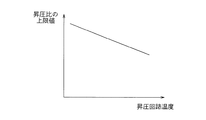
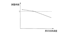
昇圧回路の温度は、モータ電流が増大するにつれて増大する。又、上述の如く、モータ電流は、モータに発生するトルクの大きさが増大するにつれて増大する。従って、昇圧回路の温度はトルクの大きさが増大するにつれて増大し、昇圧回路の温度とトルクとの間には相関関係がある。そこで、上記昇圧・弱め磁束指令生成部(58)には、昇圧回路の温度と昇圧比の上限値の図8に示す関係を表わすテーブルが格納されており、該テーブルを参照して、温度センサ(21)から得られる温度tから昇圧比の上限値αmが導出される。図示の如く昇圧回路の温度tが上昇するにつれて昇圧比の上限値αmは減小しており、モータに発生するトルクが大きい程、小さな上限値αmが導出されることになる。 The temperature of the booster circuit increases as the motor current increases. Further, as described above, the motor current increases as the magnitude of torque generated in the motor increases. Therefore, the temperature of the booster circuit increases as the magnitude of the torque increases, and there is a correlation between the temperature of the booster circuit and the torque. Therefore, a table representing the relationship shown in FIG. 8 between the temperature of the booster circuit and the upper limit value of the boost ratio is stored in the booster / weakening magnetic flux command generator (58). With reference to the table, the temperature sensor The upper limit value αm of the step-up ratio is derived from the temperature t obtained from (21). As shown in the figure, the upper limit value αm of the boost ratio decreases as the temperature t of the booster circuit increases, and the smaller the torque generated in the motor, the smaller the upper limit value αm is derived.
第3実施例
第1実施例のモータ制御装置は、昇圧比の上限値αmを可変とすることによって弱め磁束制御の開始時点を変化させるものであるのに対し、本実施例のモータ制御装置は、昇圧制御と弱め磁束制御の割合を変化させるものであって、その構成及び動作は、制御回路の昇圧・弱め磁束指令生成部を除いて、図1に示す第1実施例と同一である。
Third Embodiment The motor control device of the first embodiment changes the starting point of the flux-weakening control by making the upper limit value αm of the step-up ratio variable, whereas the motor control device of this embodiment The ratio between the boost control and the weak flux control is changed, and the configuration and operation thereof are the same as those of the first embodiment shown in FIG. 1 except for the boost / weak flux command generator of the control circuit.
本実施例の昇圧・弱め磁束指令生成部は、第1実施例と同様に、位置・速度検出部(51)から供給されるモータ回転数ωが所定の閾値以下である場合には、昇圧比の指令値αとして“1”の値を昇圧制御部(57)に供給すると共に、モータ印加電圧の制限値Vomとして所定値Vom0を弱め磁束制御部(55)に供給する。 The step-up / weakening magnetic flux command generation unit according to the present embodiment is similar to the first embodiment when the motor rotation speed ω supplied from the position / speed detection unit (51) is equal to or lower than a predetermined threshold value. A value “1” as the command value α is supplied to the boost control unit (57), and a predetermined value Vom 0 is supplied to the magnetic flux control unit (55) as the motor applied voltage limit value Vom.
その後、位置・速度検出部(51)から供給されるモータ回転数ωが所定の閾値を超えると、該モータ回転数ωに基づいて上記数2から昇圧比の目標値α*を算出する動作を開始する。
そして、上述の如く算出した目標値α*と後述の如く導出される調整係数Kとに基づいて、下記数9から昇圧比の指令値αを算出する。
(数9)
α=K・α*
Thereafter, when the motor rotational speed ω supplied from the position / speed detector (51) exceeds a predetermined threshold value, an operation for calculating the target value α * of the boost ratio from the above formula 2 based on the motor rotational speed ω is performed. Start.
Based on the target value α * calculated as described above and the adjustment coefficient K derived as described later, the command value α for the boost ratio is calculated from the following equation (9).
(Equation 9)
α = K ・ α *
更に、前記指令値αに基づいて上記数3からモータ印加電圧の制限値Vomを算出し、前記指令値αを昇圧制御部(57)に供給すると共に、該制限値Vomを弱め磁束制御部(55)に供給する。
Further, the limit value Vom of the motor applied voltage is calculated from the
上述の調整係数Kは、後述の如く導出される。
昇圧・弱め磁束指令生成部には、モータ電流のq軸方向成分と調整係数の図9に示す関係を表わすテーブルが格納されており、該テーブルを参照して、電流検出部(52)から供給されるq軸方向電流iqから調整係数Kが導出される。図示の如くq軸方向電流iqが増大するにつれて調整係数Kは減小しており、モータに発生するトルクが大きい程、小さな調整係数Kが導出されることになる。
The adjustment coefficient K described above is derived as described later.
The step-up / weakening magnetic flux command generation unit stores a table showing the relationship between the q-axis direction component of the motor current and the adjustment coefficient shown in FIG. 9, and is supplied from the current detection unit (52) with reference to the table. The adjustment coefficient K is derived from the q-axis direction current iq. As shown in the figure, the adjustment coefficient K decreases as the q-axis direction current iq increases. As the torque generated in the motor increases, the smaller adjustment coefficient K is derived.
昇圧制御部(57)では、昇圧・弱め磁束指令生成部から供給される昇圧指令値αに基づき昇圧回路(2)のスイッチング素子に対するスイッチング信号が作成されて昇圧回路(2)に供給される。これによって、昇圧回路(2)の出力電圧は、図10に示す如く、モータの回転数ωが前記所定の閾値を超えるまでは、昇圧比が“1”に設定されて一定値となり、モータ回転数ωが前記所定の閾値を超えると、該回転数ωが増大するにつれて昇圧比が徐々に大きな値に設定されて徐々に増大する。ここで、調整係数Kは、上述の如くモータに発生するトルクが大きい程、小さな値に設定されるので、該トルクが大きい程、小さな昇圧指令値αが算出されることとなり、図示の如く、高トルク時における昇圧回路(2)の出力電圧は、低トルク時に比べて低くなる。 In the boosting control unit (57), a switching signal for the switching element of the boosting circuit (2) is created based on the boosting command value α supplied from the boosting / weakening magnetic flux command generating unit and supplied to the boosting circuit (2). As a result, as shown in FIG. 10, the output voltage of the booster circuit (2) becomes a constant value with the boost ratio set to “1” until the rotational speed ω of the motor exceeds the predetermined threshold value. When the number ω exceeds the predetermined threshold value, the step-up ratio is gradually set to a larger value and gradually increases as the rotational speed ω increases. Here, the adjustment coefficient K is set to a smaller value as the torque generated in the motor is larger as described above. Therefore, the smaller the torque is, the smaller the boost command value α is calculated. The output voltage of the booster circuit (2) at high torque is lower than that at low torque.
図1の弱め磁束制御部(55)では、モータ印加電圧の振幅値Vaが昇圧・弱め磁束指令生成部(54)から供給される制限値Vomを下回る場合には、モータ電流のd軸方向成分の目標値id*として、モータに発生するトルクが最大となる値がPWM制御部(56)に供給される。
これに対し、前記振幅値Vaが前記制限値Vom以上である場合には、上記数5から、目標d軸方向電流id*が算出されてPWM制御部(56)に供給される。
In the weak flux control unit (55) of FIG. 1, when the amplitude value Va of the motor applied voltage is lower than the limit value Vom supplied from the boost / weak flux command generation unit (54), the d-axis direction component of the motor current As the target value id * , a value that maximizes the torque generated in the motor is supplied to the PWM controller (56).
On the other hand, when the amplitude value Va is equal to or greater than the limit value Vom, the target d-axis direction current id * is calculated from the
PWM制御部(56)では、第1実施例と同様にして、u相、v相、w相のPWM信号が作成されてドライブ回路(6)に供給され、該ドライブ回路(6)では、これらのPWM信号に基づきインバータ(3)に対するドライブ信号が作成されてインバータ(3)に供給され、インバータ(3)が制御される。この結果、ブラシレスモータ(4)が駆動されることになる。 In the PWM controller (56), the u-phase, v-phase, and w-phase PWM signals are generated and supplied to the drive circuit (6) in the same manner as in the first embodiment, and the drive circuit (6) Based on the PWM signal, a drive signal for the inverter (3) is created and supplied to the inverter (3) to control the inverter (3). As a result, the brushless motor (4) is driven.
本実施例のモータ制御装置においては、上述の如く、モータに発生するトルクの大きさに応じた調整係数Kが算出されて、昇圧比の目標値に該調整係数Kを乗算することによって昇圧指令値αが算出され、該昇圧指令値αから上記数3を用いてモータ印加電圧の制限値Vomが算出される。従って、該制限値Vomは、トルクの大きさに応じた値となり、弱め磁束制御部(55)にてモータ印加電圧の振幅値Vaがモータ印加電圧の制限値Vom以上であると判断されて弱め磁束制御が開始される時点がトルクの大きさに応じて変化することになる。又、昇圧制御の割合と弱め磁束制御の割合がトルクの大きさに応じて変化することになる。即ち、高トルク時には、低トルク時に比べて小さな昇圧指令値αが算出されて、小さな制限値Vomが算出される。従って、弱め磁束制御部(55)にてモータ印加電圧の振幅値Vaがモータ印加電圧の制限値Vom以上であると判断される時点が早くなって、低トルク時よりも小さな回転数で弱め磁束制御が開始されることになる。又、昇圧制御の割合が低トルク時よりも小さくなる。
In the motor control apparatus of the present embodiment, as described above, the adjustment coefficient K corresponding to the magnitude of the torque generated in the motor is calculated, and the target value of the boost ratio is multiplied by the adjustment coefficient K to increase the boost command. The value α is calculated, and the limit value Vom of the motor applied voltage is calculated from the boost command value α using the
本実施例のモータ制御装置においては、高トルク時には、低トルク時よりも小さな回転数で第3制御動作を開始すると共に昇圧制御の割合を小さくすることによって、昇圧回路での損失の増大を抑えて昇圧回路の温度上昇を抑制することが出来る。一方、低トルク時には、弱め磁束制御による損失の増大を抑えてモータの温度上昇を抑制することが出来る。 In the motor control device of this embodiment, at the time of high torque, the third control operation is started at a smaller number of rotations than at the time of low torque, and the increase in loss in the booster circuit is suppressed by reducing the boost control ratio. Thus, the temperature rise of the booster circuit can be suppressed. On the other hand, at the time of low torque, it is possible to suppress an increase in loss due to the magnetic flux weakening control and suppress an increase in the temperature of the motor.
第4実施例
第3実施例のモータ制御装置は、モータ電流のq軸方向成分iqから調整係数Kを導出しているが、本実施例のモータ制御装置は、昇圧回路の温度から調整係数を導出するものである。
本実施例の制御回路の構成及び動作は、昇圧・弱め磁束指令生成部を除いて、図7に示す第2実施例の制御回路(50)と同一であるので、それらの説明は省略する。
Fourth Embodiment Although the motor control device of the third embodiment derives the adjustment coefficient K from the q-axis direction component iq of the motor current, the motor control device of this embodiment calculates the adjustment coefficient from the temperature of the booster circuit. To derive.
Since the configuration and operation of the control circuit of the present embodiment are the same as those of the control circuit (50) of the second embodiment shown in FIG. 7 except for the step-up / weakening magnetic flux command generation unit, description thereof will be omitted.
昇圧回路の温度は、モータ電流が増大するにつれて増大する。又、上述の如く、モータ電流は、モータに発生するトルクの大きさが増大するにつれて増大する。従って、昇圧回路の温度はトルクの大きさが増大するにつれて増大し、昇圧回路の温度とトルクとの間には相関関係がある。そこで、上記昇圧・弱め磁束指令生成部には、昇圧回路の温度と調整係数の図11に示す関係を表わすテーブルが格納されており、該テーブルを参照して、温度センサ(21)から得られる温度tから調整係数Kが導出される。図示の如く昇圧回路の温度tが上昇するにつれて調整係数Kは減小しており、モータに発生するトルクが大きい程、小さな調整係数Kが導出されることになる。 The temperature of the booster circuit increases as the motor current increases. Further, as described above, the motor current increases as the magnitude of torque generated in the motor increases. Therefore, the temperature of the booster circuit increases as the magnitude of the torque increases, and there is a correlation between the temperature of the booster circuit and the torque. Therefore, a table representing the relationship between the temperature of the booster circuit and the adjustment coefficient shown in FIG. 11 is stored in the booster / weakening magnetic flux command generator, and is obtained from the temperature sensor (21) with reference to the table. An adjustment factor K is derived from the temperature t. As shown in the figure, the adjustment coefficient K decreases as the temperature t of the booster circuit increases, and the smaller the torque generated in the motor, the smaller the adjustment coefficient K is derived.
(1) 直流電源
(2) 昇圧回路
(3) インバータ
(4) ブラシレスモータ
(40) 位置センサ
(41) 電流センサ
(5) 制御回路
(51) 位置・速度検出部
(52) 電流検出部
(53) 速度制御部
(54) 昇圧・弱め磁束指令生成部
(55) 弱め磁束制御部
(56) PWM制御部
(57) 昇圧制御部
(6) ドライブ回路
(1) DC power supply
(2) Booster circuit
(3) Inverter
(4) Brushless motor
(40) Position sensor
(41) Current sensor
(5) Control circuit
(51) Position / speed detector
(52) Current detector
(53) Speed controller
(54) Step-up / weakening magnetic flux command generator
(55) Weak magnetic flux controller
(56) PWM controller
(57) Boost controller
(6) Drive circuit
Claims (7)
該制御回路は、ブラシレスモータに発生するトルクの大きさに応じて、前記第3制御動作の弱め磁束制御動作を開始する時点を変化させ、前記第2制御動作から前記第3制御動作に制御動作が切り替わるタイミングを制御することを特徴とするブラシレスモータの制御装置。 A boost circuit that boosts a DC input voltage; an inverter that converts the output voltage of the boost circuit into AC and supplies the brushless motor; and a control circuit that controls the boost ratio of the boost circuit and the operation of the inverter. The circuit executes, as a second control operation, a boost control operation for setting the boost ratio of the booster circuit to a value larger than 1 , and further performs an operation for reducing the magnetic flux generated from the boost control operation and the brushless motor. In the brushless motor control device that executes the weak flux control operation to be executed as the third control operation ,
The control circuit changes the time point at which the magnetic flux weakening control operation of the third control operation starts according to the magnitude of the torque generated in the brushless motor, and performs the control operation from the second control operation to the third control operation. A control device for a brushless motor, characterized by controlling the timing at which the motor is switched .
外部から供給される昇圧指令値に基づいて昇圧制御動作を実行する昇圧制御手段と、
ブラシレスモータに対する印加電圧の大きさと、外部から供給されるモータ印加電圧制限値とを比較し、その比較結果に基づいて弱め磁束制御動作を開始する磁束制御手段と、
昇圧指令値を前記昇圧制御手段に供給すると共に、モータ印加電圧制限値を前記磁束制御手段に供給する値供給手段
とを具え、該値供給手段は、
モータ電流の大きさ或いは該モータ電流の大きさに応じた値と昇圧比或いは昇圧回路の出力電圧の上限値との関係が規定されている第1関係規定手段と、
第1関係規定手段に規定されている関係に従って、モータ電流の大きさ或いは該モータ電流の大きさに応じた値から昇圧比或いは昇圧回路の出力電圧の上限値を導出する手段と、
昇圧比或いは昇圧回路の出力電圧の目標値が導出された上限値以下である場合には、該目標値を昇圧指令値として昇圧制御手段に供給する一方、該目標値が導出された上限値を上回る場合には、該上限値を昇圧指令値として昇圧制御手段に供給する手段と、
昇圧指令値とモータ印加電圧制限値の関係が規定されている第2関係規定手段と、
第2関係規定手段に規定されている関係に従って、昇圧制御手段に供給する昇圧指令値からモータ印加電圧制限値を導出して、磁束制御手段に供給する手段
とを具えている請求項2に記載の制御装置。 The control circuit includes:
A boost control means for executing a boost control operation based on a boost command value supplied from the outside;
A magnetic flux control means for comparing the magnitude of the applied voltage to the brushless motor with a motor applied voltage limit value supplied from the outside, and starting a weakening magnetic flux control operation based on the comparison result;
A value supply means for supplying a boost command value to the boost control means and supplying a motor applied voltage limit value to the magnetic flux control means, the value supply means,
A first relationship defining means for defining a relationship between the magnitude of the motor current or a value corresponding to the magnitude of the motor current and the boost ratio or the upper limit value of the output voltage of the booster circuit;
Means for deriving the step-up ratio or the upper limit value of the output voltage of the step-up circuit from the magnitude of the motor current or a value corresponding to the magnitude of the motor current in accordance with the relation prescribed in the first relation defining means;
When the target value of the boost ratio or the output voltage of the booster circuit is less than or equal to the derived upper limit value, the target value is supplied as a boost command value to the boost control means, while the upper limit value from which the target value is derived is When exceeding, means for supplying the upper limit value to the boost control means as a boost command value;
A second relationship defining means for defining a relationship between the boost command value and the motor applied voltage limit value;
3. A means for deriving a motor applied voltage limit value from a boost command value supplied to the boost control means in accordance with a relationship prescribed in the second relation defining means and supplying the limit value to the magnetic flux control means. Control device.
値供給手段から供給されるモータ印加電圧制限値からモータ電流の磁束方向成分の大きさの目標値を表わす目標電流値を導出する手段と、
電流検出手段によって検出された電流値と導出された目標電流値とに基づき制御信号を作成してインバータに供給する手段
とを具えている請求項3に記載の制御装置。 The control circuit comprises current detection means for detecting the magnitude of the magnetic flux direction component of the motor current, and the magnetic flux control means comprises:
Means for deriving a target current value representing a target value of the magnitude of the magnetic flux direction component of the motor current from the motor applied voltage limit value supplied from the value supply means;
4. The control apparatus according to claim 3, further comprising means for generating a control signal based on the current value detected by the current detection means and the derived target current value and supplying the control signal to the inverter.
外部から供給される昇圧指令値に基づいて昇圧制御動作を実行する昇圧制御手段と、
ブラシレスモータに対する印加電圧の大きさと、外部から供給されるモータ印加電圧制限値とを比較し、その比較結果に基づいて弱め磁束制御動作を開始すると共に、該モータ印加電圧制限値に基づいて弱め磁束制御動作を実行する磁束制御手段と、
昇圧指令値を前記昇圧制御手段に供給すると共に、モータ印加電圧制限値を前記磁束制御手段に供給する値供給手段
とを具え、該値供給手段は、
モータ電流の大きさ或いは該モータ電流の大きさに応じた値と前記係数との関係が規定されている第1関係規定手段と、
第1関係規定手段に規定されている関係に従って、モータ電流の大きさ或いは該モータ電流の大きさに応じた値から前記係数を導出する手段と、
昇圧比或いは昇圧回路の出力電圧の目標値に対し導出された係数を用いた演算処理を施して昇圧指令値を算出する手段と、
算出された昇圧指令値を昇圧制御手段に供給する手段と、
昇圧指令値とモータ印加電圧制限値の関係が規定されている第2関係規定手段と、
第2関係規定手段に規定されている関係に従って、前記算出された昇圧指令値からモータ印加電圧制限値を導出して、磁束制御手段に供給する手段
とを具えている請求項5に記載の制御装置。 The control circuit includes:
A boost control means for executing a boost control operation based on a boost command value supplied from the outside;
And the magnitude of the voltage applied to the brushless motor, compares a motor applied voltage limit value supplied from the outside, and starts the flux control operation weakening based on the comparison result, the magnetic flux weakening on the basis of the motor applied voltage limit value Magnetic flux control means for executing a control operation;
A value supply means for supplying a boost command value to the boost control means and supplying a motor applied voltage limit value to the magnetic flux control means, the value supply means,
A first relationship defining means in which a relationship between the magnitude of the motor current or a value corresponding to the magnitude of the motor current and the coefficient is defined;
Means for deriving the coefficient from the magnitude of the motor current or a value corresponding to the magnitude of the motor current according to the relation prescribed in the first relation defining means;
Means for calculating a boost command value by performing arithmetic processing using a coefficient derived for a boost ratio or a target value of the output voltage of the booster circuit;
Means for supplying the calculated boost command value to the boost control means;
A second relationship defining means for defining a relationship between the boost command value and the motor applied voltage limit value;
6. The control according to claim 5, further comprising means for deriving a motor applied voltage limit value from the calculated boost command value in accordance with a relation prescribed in the second relation defining means and supplying the motor applied voltage limit value to the magnetic flux control means. apparatus.
値供給手段から供給されるモータ印加電圧制限値からモータ電流の磁束方向成分の大きさの目標値を表わす目標電流値を導出する手段と、
電流検出手段によって検出された電流値と導出された目標電流値とに基づき制御信号を作成してインバータに供給する手段
とを具えている請求項6に記載の制御装置。
The control circuit comprises current detection means for detecting the magnitude of the magnetic flux direction component of the motor current, and the magnetic flux control means comprises:
Means for deriving a target current value representing a target value of the magnitude of the magnetic flux direction component of the motor current from the motor applied voltage limit value supplied from the value supply means;
7. The control apparatus according to claim 6, further comprising means for generating a control signal based on the current value detected by the current detection means and the derived target current value and supplying the control signal to the inverter.
Priority Applications (1)
| Application Number | Priority Date | Filing Date | Title |
|---|---|---|---|
| JP2004194390A JP4476049B2 (en) | 2004-06-30 | 2004-06-30 | Brushless motor control device |
Applications Claiming Priority (1)
| Application Number | Priority Date | Filing Date | Title |
|---|---|---|---|
| JP2004194390A JP4476049B2 (en) | 2004-06-30 | 2004-06-30 | Brushless motor control device |
Publications (2)
| Publication Number | Publication Date |
|---|---|
| JP2006020399A JP2006020399A (en) | 2006-01-19 |
| JP4476049B2 true JP4476049B2 (en) | 2010-06-09 |
Family
ID=35794127
Family Applications (1)
| Application Number | Title | Priority Date | Filing Date |
|---|---|---|---|
| JP2004194390A Expired - Fee Related JP4476049B2 (en) | 2004-06-30 | 2004-06-30 | Brushless motor control device |
Country Status (1)
| Country | Link |
|---|---|
| JP (1) | JP4476049B2 (en) |
Families Citing this family (6)
| Publication number | Priority date | Publication date | Assignee | Title |
|---|---|---|---|---|
| JP4712585B2 (en) * | 2006-03-22 | 2011-06-29 | 本田技研工業株式会社 | Electric motor control device |
| JP2008035688A (en) * | 2006-06-26 | 2008-02-14 | Sanyo Electric Co Ltd | Drive unit of motor |
| JP5104723B2 (en) * | 2007-11-01 | 2012-12-19 | アイシン・エィ・ダブリュ株式会社 | Electric motor control device, drive device and hybrid drive device |
| JP5246508B2 (en) * | 2009-05-28 | 2013-07-24 | アイシン・エィ・ダブリュ株式会社 | Control device for motor drive device |
| CN111238099A (en) * | 2018-11-28 | 2020-06-05 | 青岛海尔空调电子有限公司 | Compressor flux weakening control device, air conditioner, method and storage medium |
| CN112524853B (en) * | 2020-12-09 | 2023-06-23 | 青岛海尔空调器有限总公司 | Control method of compressor in variable frequency air conditioner and variable frequency air conditioner |
-
2004
- 2004-06-30 JP JP2004194390A patent/JP4476049B2/en not_active Expired - Fee Related
Also Published As
| Publication number | Publication date |
|---|---|
| JP2006020399A (en) | 2006-01-19 |
Similar Documents
| Publication | Publication Date | Title |
|---|---|---|
| JP5321614B2 (en) | Rotating machine control device | |
| US10008970B2 (en) | Control apparatus for AC motor | |
| JP5133834B2 (en) | AC motor control device | |
| JP6593242B2 (en) | AC motor control device | |
| JP6275214B2 (en) | Control device and control method for rotating electrical machine for vehicle | |
| JP2006129632A (en) | Motor drive unit | |
| US10910974B2 (en) | Control device for AC motor | |
| JP4008930B2 (en) | Motor control device | |
| JP2006304441A (en) | Synchronous motor control device | |
| JP4476049B2 (en) | Brushless motor control device | |
| JP4811290B2 (en) | Motor control drive device | |
| JP2009124799A (en) | Motor controller | |
| JP4611216B2 (en) | AC motor control device and control method | |
| JP4007309B2 (en) | Motor control device and motor control method | |
| JP6384355B2 (en) | SR motor control device | |
| JP5862690B2 (en) | Control device for motor drive device and motor drive system | |
| JP7073799B2 (en) | Motor control method and motor control device | |
| JP2005269722A (en) | Motor drive controller | |
| JP2007312462A (en) | Motor control device | |
| JP2020089203A (en) | Motor drive device | |
| JP5862691B2 (en) | Control device for motor drive device and motor drive system | |
| JP6249923B2 (en) | Motor control device | |
| JP2008193790A (en) | Electric motor driver for turbocharger with electric motor | |
| JP2012076694A (en) | Electric power steering device | |
| WO2023281794A1 (en) | Motor control device, motor control method, steering system, and vehicle drive system |
Legal Events
| Date | Code | Title | Description |
|---|---|---|---|
| A621 | Written request for application examination |
Free format text: JAPANESE INTERMEDIATE CODE: A621 Effective date: 20060405 |
|
| A977 | Report on retrieval |
Free format text: JAPANESE INTERMEDIATE CODE: A971007 Effective date: 20090325 |
|
| A131 | Notification of reasons for refusal |
Free format text: JAPANESE INTERMEDIATE CODE: A131 Effective date: 20090406 |
|
| A521 | Written amendment |
Free format text: JAPANESE INTERMEDIATE CODE: A523 Effective date: 20090608 |
|
| A072 | Dismissal of procedure |
Free format text: JAPANESE INTERMEDIATE CODE: A072 Effective date: 20090728 |
|
| A131 | Notification of reasons for refusal |
Free format text: JAPANESE INTERMEDIATE CODE: A131 Effective date: 20090812 |
|
| A521 | Written amendment |
Free format text: JAPANESE INTERMEDIATE CODE: A523 Effective date: 20090908 |
|
| TRDD | Decision of grant or rejection written | ||
| A01 | Written decision to grant a patent or to grant a registration (utility model) |
Free format text: JAPANESE INTERMEDIATE CODE: A01 Effective date: 20100212 |
|
| A01 | Written decision to grant a patent or to grant a registration (utility model) |
Free format text: JAPANESE INTERMEDIATE CODE: A01 |
|
| A61 | First payment of annual fees (during grant procedure) |
Free format text: JAPANESE INTERMEDIATE CODE: A61 Effective date: 20100309 |
|
| FPAY | Renewal fee payment (event date is renewal date of database) |
Free format text: PAYMENT UNTIL: 20130319 Year of fee payment: 3 |
|
| FPAY | Renewal fee payment (event date is renewal date of database) |
Free format text: PAYMENT UNTIL: 20140319 Year of fee payment: 4 |
|
| LAPS | Cancellation because of no payment of annual fees |