JP4476016B2 - Manufacturing method of steel / aluminum joint structure - Google Patents
Manufacturing method of steel / aluminum joint structure Download PDFInfo
- Publication number
- JP4476016B2 JP4476016B2 JP2004139286A JP2004139286A JP4476016B2 JP 4476016 B2 JP4476016 B2 JP 4476016B2 JP 2004139286 A JP2004139286 A JP 2004139286A JP 2004139286 A JP2004139286 A JP 2004139286A JP 4476016 B2 JP4476016 B2 JP 4476016B2
- Authority
- JP
- Japan
- Prior art keywords
- aluminum
- mass
- alloy layer
- steel
- layer
- Prior art date
- Legal status (The legal status is an assumption and is not a legal conclusion. Google has not performed a legal analysis and makes no representation as to the accuracy of the status listed.)
- Active
Links
Images


Description
本発明は、アルミニウム材料の優れた軽量性,耐食性と鋼材の優れた機械強度を兼ね備えた鋼/アルミニウムの接合構造体を製造する方法に関する。 The present invention relates to a method for producing a steel / aluminum bonded structure that combines the excellent lightness and corrosion resistance of an aluminum material with the excellent mechanical strength of a steel material.
アルミニウム,アルミニウム合金等のアルミニウム材料は、軽量で耐食性に優れていることを活用し種々の分野で使用されているが、強度が要求される用途では厚肉化によって要求強度を満足させている。しかし、厚肉化はアルミニウム材料の長所である軽量性が損ない、コンパクトな設計に対応する構造部材としても適当でない。機械強度の良好な鋼材をアルミニウム材料と積層するとき、厚肉化の要なく必要強度が得られる。 Aluminum materials such as aluminum and aluminum alloys are used in various fields by utilizing their light weight and excellent corrosion resistance. However, in applications where strength is required, the required strength is satisfied by increasing the thickness. However, thickening impairs the lightness that is an advantage of the aluminum material, and is not suitable as a structural member corresponding to a compact design. When a steel material with good mechanical strength is laminated with an aluminum material, the required strength can be obtained without the need for thickening.
アルミニウム材料と鋼材との積層には、ボルトナット,リベット,嵌め合せ等の機械的結合法が採用されてきたが、機械的結合法では優れた継手が得られがたく、生産性も低い。アルミニウム材料/鋼材の溶接接合が可能になると、機械的結合法に比較して生産性が格段に高く、良好な特性をもつ鋼/アルミニウムの接合構造体が得られる。ところが、通常の溶融接合法で鋼材,アルミニウム材料を接合すると、非常に脆弱な金属間化合物が接合界面に多量生成し継手強度が著しく低下する。 For the lamination of the aluminum material and the steel material, mechanical coupling methods such as bolts, nuts, rivets, and fitting have been adopted, but it is difficult to obtain excellent joints by the mechanical coupling method, and the productivity is low. When the aluminum material / steel material can be welded, a steel / aluminum bonded structure having significantly higher productivity and good characteristics can be obtained as compared with the mechanical bonding method. However, when steel materials and aluminum materials are joined by a normal melt joining method, a large amount of very fragile intermetallic compounds are generated at the joining interface, and the joint strength is significantly reduced.
金属間化合物は、鋼材,アルミニウム材料の原子が界面で相互拡散反応することにより生成する。特許文献1では、拡散反応を律則する反応温度,時間等を摩擦溶接時に適正管理することにより金属間化合物の生成を抑えている。しかし、摩擦溶接による接合であることから、継手設計に工夫を要し、接合工程を簡略化する上では改善の余地がある。スポット溶接の適用も検討されており、特許文献2では溶融アルミニウムめっき鋼板をアルミニウム材料に抵抗溶接する方法を紹介している。
An intermetallic compound is produced by an interdiffusion reaction of atoms of steel and aluminum materials at the interface. In
溶融アルミニウムめっき鋼板は、表層に溶融アルミニウムめっき層があることから接合時にアルミニウム材料と同様な挙動を示すと考えられがちである。しかし、接合界面は、スポット溶接時にAlの融点(660℃)を超える高温に加熱される。高温加熱で生成した溶融Alに下地鋼/めっき層界面のAl−Fe−Si三元合金層からFe,Si等が拡散するが、溶接時の冷却過程でFeが再析出し、拡散係数の大きなSiは溶融Alに分散される。その結果、冷却後の接合界面を観察すると接合界面全域に脆弱なAl−Fe二元合金層が生成したナゲットが検出され、継手強度も著しく低い。 A hot-dip aluminum-plated steel sheet tends to be considered to exhibit a behavior similar to that of an aluminum material at the time of joining since a hot-dip aluminum plating layer is present on the surface layer. However, the joint interface is heated to a high temperature exceeding the melting point of Al (660 ° C.) during spot welding. Fe, Si, etc. diffuse from the Al—Fe—Si ternary alloy layer at the base steel / plating layer interface into the molten Al produced by high-temperature heating, but Fe reprecipitates during the cooling process during welding, resulting in a large diffusion coefficient. Si is dispersed in molten Al. As a result, when the bonded interface after cooling is observed, a nugget in which a fragile Al—Fe binary alloy layer is formed in the entire bonded interface is detected, and the joint strength is extremely low.
継手強度に及ぼすAl−Fe二元合金層の悪影響を抑制するため、特許文献3では接合界面に占める金属間化合物の割合を規制している。金属間化合物の生成抑制には、溶融アルミニウムめっき鋼板を正極側,アルミニウム材料を負極側にしてスポット溶接時の発熱を溶融アルミニウムめっき鋼板に偏らせる方法を採用しているが、依然として金属間化合物の多量生成が避けられない。
本発明は、このような問題を解消すべく案出されたものであり、スポット溶接時の高温加熱で溶融したAlに拡散し再析出するFe,Siの挙動を調査・検討した結果、ナゲット中心部から半径方向に沿った入熱分布を調整することにより、継手強度に有害なAl-Fe二元合金層の生成・成長を抑え、継手強度の高い鋼/アルミニウムの接合構造体を提供することを目的とする。 The present invention has been devised to solve such problems, and as a result of investigating and examining the behavior of Fe and Si that diffuses and reprecipitates in molten Al by high-temperature heating during spot welding, the nugget center The steel / aluminum joint structure with high joint strength by controlling the heat input distribution along the radial direction from the joint to suppress the formation and growth of Al-Fe binary alloy layers harmful to joint strength With the goal.
本発明の製造方法は、Si:3〜12質量%,Fe:0.5〜5質量%,残部:実質的にAlのめっき層が形成されるとともに、めっき層/下地鋼の界面に0.1μm以上の厚さを有するAl‐Fe‐Si三元合金層が形成されている溶融アルミニウムめっき鋼板にアルミニウム又はアルミニウム合金を重ね合わせ、アールを先端につけた電極で溶融アルミニウムめっき鋼板及びアルミニウム又はアルミニウム合金を加圧し、スポット溶接することを特徴とする。 In the production method of the present invention, Si: 3 to 12% by mass, Fe: 0.5 to 5% by mass, and the balance: a substantially Al plating layer is formed, and at the plating layer / underlying steel interface, 0.5% is formed . Aluminum or aluminum alloy is superimposed on a hot-dip aluminum-plated steel sheet on which an Al-Fe-Si ternary alloy layer having a thickness of 1 μm or more is formed. And spot welding.
溶融アルミニウムめっき鋼板としては、N:0.002〜0.020質量%を含む鋼材を下地鋼とし、下地鋼と溶融アルミニウムめっき層の界面にN:3.0原子%以上のN濃縮層が形成されているめっき鋼板も好適な被接合材である。相手材のアルミニウム材料は好ましくはFe含有量が0.1質量%以下に規制され、必要に応じてMg:0.1〜.6.0質量%,Si:3.0質量%以下を含むアルミニウム合金が使用される。 As a hot-dip aluminum-plated steel sheet, a steel material containing 0.002 to 0.020 mass% of N is used as a base steel, and an N-concentrated layer of N: 3.0 atomic% or more is formed at the interface between the base steel and the hot-dip aluminum plating layer. A plated steel sheet is also a suitable material to be joined. The aluminum material of the counterpart material is preferably aluminum whose Fe content is regulated to 0.1% by mass or less and includes Mg: 0.1 to 6.0% by mass, Si: 3.0% by mass or less as required. An alloy is used.
先端にアールをつけた電極を用いて溶融アルミニウムめっき鋼板,アルミニウム材料を通電加熱するとき、電極中心部が最も高い温度に加熱され、電極周辺に向かうほど温度が低くなる。この温度勾配に応じ、電極中心部に相当する部分ではAl-Fe二元合金層が生成するが、電極中心部から遠ざかるほどAl-Fe二元合金層の生成が少なくなり、合金層消失域をもつナゲットが形成される。好適な温度勾配を与える電極としては、たとえばアール:5〜300mmを先端につけた電極が使用される。 When a hot-dip aluminized steel sheet or aluminum material is energized and heated using an electrode with a rounded tip, the center of the electrode is heated to the highest temperature, and the temperature decreases toward the periphery of the electrode. According to this temperature gradient, an Al-Fe binary alloy layer is formed in the part corresponding to the center of the electrode, but as the distance from the center of the electrode increases, the generation of the Al-Fe binary alloy layer decreases, and the alloy layer disappearing region is reduced. A nugget is formed. As an electrode that provides a suitable temperature gradient, for example, an electrode having a round tip of 5 to 300 mm is used.
溶融アルミニウムめっき鋼板/アルミニウム板のスポット溶接に際しては、溶融アルミニウムめっき鋼板1,アルミニウム材料2を重ね合わせて電極3で押さえ込み、たとえば3kN程度の加圧条件下、溶接電流:15〜25kA,通電時間:3〜40サイクルで通電する。通電による発熱で接合部のアルミニウム材料2,溶融アルミニウムめっき層4が溶融し、相互拡散反応によって融合する。
In spot welding of a hot-dip aluminum plated steel plate / aluminum plate, the hot-dip aluminum plated
下地鋼5/めっき層4の界面に生成しているAl-Fe-Si三元合金層6から溶融AlにFe,Siが溶け込み、接合界面ではAl-Fe-Si三元合金層6が消失する。下地鋼5から溶融Alに溶け込むFeもある。溶け込んだFeは溶接時の冷却過程で再析出し、脆弱なAl-Fe二元合金層7が接合界面に生成されがちである。このとき、鋼板/アルミニウム材料2の接合にみられるように、接合界面全域にAl-Fe二元合金層7が生成すると、継手強度が極端に低下したナゲット8が形成される(図1a)。他方、Al-Fe二元合金層7がナゲット8の全域まで成長しておらず、めっき層4が下地鋼5に直接密着した合金層消失域9が存在すると、この部分で接合状態が保たれる(図1b)。合金層消失域9が広がるほど、継手強度が高くなる。
Fe and Si dissolve into the molten Al from the Al—Fe—Si
本発明者等は、図1bの接合界面が得られる条件を種々調査・検討した結果、被接合材である溶融アルミニウムめっき鋼板のめっき層組成及び溶接時の通電条件が接合界面のAl-Fe二元合金層生成に大きな影響を及ぼしていることを見出した。
Si:3〜12質量%,Fe:0.5〜5質量%を含む溶融アルミニウムめっき層が形成されている溶融アルミニウムめっき鋼板をアルミニウム材料とスポット溶接で接合する場合、合金層消失域9のある接合界面が形成される。溶融アルミニウムめっき層のSi,Fe濃度がAl-Fe二元合金層の生成に及ぼす影響は、次のように推察される。
As a result of various investigations and examinations on the conditions for obtaining the joint interface shown in FIG. 1b, the present inventors have found that the composition of the plated layer of the hot-dip galvanized steel sheet as the material to be joined and the current-carrying conditions during welding are Al—Fe It has been found that it has a great influence on the formation of the original alloy layer.
When a hot-dip aluminum-plated steel sheet on which a hot-dip aluminum plating layer containing Si: 3 to 12 mass% and Fe: 0.5 to 5 mass% is formed is joined with an aluminum material by spot welding, there is an alloy layer disappearance zone 9 A bonding interface is formed. The influence of the Si and Fe concentration of the molten aluminum plating layer on the formation of the Al—Fe binary alloy layer is presumed as follows.
Al-Fe二元合金層7は、スポット溶接時の高温加熱で生成した溶融Alに溶け込んだFeが冷却過程で再析出した結果である。溶融Alに対するFeの溶込み量は、下地鋼/めっき層のFeの濃度勾配に影響され、濃度勾配が大きいほど(換言すれば、めっき層のFe濃度が低いほど)多くなる。溶出したFeは、拡散係数が比較的小さいことから下地鋼の近傍に存在し、冷却過程で多量のAl−Fe二元合金層7となって接合界面に再析出する。そこで、めっき層4のFe濃度を予め高くしておくと、下地鋼5からめっき層4に溶け込むFeが少なくなり、結果としてAl-Fe二元合金層7の生成が抑えられる。
The Al—Fe
めっき層4に含まれるSiは、Feに比較して拡散係数が大きく、スポット溶接時の高温加熱でAl-Fe-Si三元合金層6から溶融Alに容易に移行し、ナゲット8に分散される。そこで、めっき層4のSi濃度を3〜12質量%と高めに設定することにより、Al-Fe-Si三元合金層6から溶融AlへのSi拡散を遅延させる。
溶融AlへのFe,Siの拡散は、一般的に高温になるほど活発に進行する。実際、過剰電力を投入した溶接部では接合界面全域にAl-Fe二元合金層7が厚く生成・成長するが、投入電力の低減に伴ってAl-Fe二元合金層7が薄くなる。したがって、溶接時の最高到達温度が電極中心部で高く、電極周辺に向けて低くなる温度勾配をつけることができれば、接合界面の中心ではAl-Fe二元合金層7が生成するものの、周辺ではAl-Fe二元合金層7が薄く、更には合金層消失域9のある接合界面となることが予想される。
Si contained in the
In general, diffusion of Fe and Si into molten Al progresses more actively as the temperature becomes higher. Actually, the Al—Fe
本発明では、先端にアールをつけた電極を使用することにより、Al-Fe二元合金層7の生成抑制に有効な温度勾配を実現している。アールを付けた電極3をアルミニウム材料2に押し付けると、電極3の中心部はアルミニウム材料2に密着するが、周辺に向かうほどアルミニウム材料2/電極3の接触圧が低下する(図2)。アルミニウム材料2に対する電極3の接触状態に応じて、スポット溶接時の電流も電極3の中央部で多く、周辺部で少なく流れる。その結果、電極3の中心に当る部分でアルミニウム材料2が最も高温になり、周辺に向かって最高到達温度が低い温度分布が得られる。
In the present invention, a temperature gradient effective for suppressing the formation of the Al—Fe
電極3の周辺に当る接合部の最高到達温度が低下しているので、Al−Fe二元合金層7の生成・成長が抑制され、合金層消失域9が生成する。最高到達温度が低い周辺部では、めっき層/下地鋼の界面にあるAl−Fe−Si三元合金層6から溶融AlへのFe,Si拡散が少なくなるので、溶接後にもAl−Fe−Si三元合金層6の一部が接合界面に残存する。これによっても、継手強度の向上が図られる。
Since the maximum temperature reached at the joint that hits the periphery of the
下地鋼5から溶融AlへのFe拡散は、下地鋼/めっき層界面にFe拡散防止層を形成することによっても抑えられる。Fe拡散防止層としては、本出願人が開発したブレージング用アルミニウムめっき鋼板(特許文献4)として本出願人が開発したN濃縮層が有効である。N濃縮層によって下地鋼5から溶融Alに溶け込むFeが少なくなるので、接合界面に生成する脆弱なAl-Fe二元合金層7が一層減少し、継手強度の高い接合構造体が得られる。
めっき原板には、低炭素鋼,中炭素鋼,低合金鋼,ステンレス鋼等があり、用途に応じてSi,Mn,Cr,Ni等を添加した鋼種が使用される。なかでも、Al-Feの相互拡散を抑制するNを0.002〜0.020質量%添加しためっき原板が好ましい。
めっき原板を溶融アルミニウムめっき浴に浸漬して引き上げると、めっき原板に随伴して溶融めっき浴から持ち上げられた溶融めっき金属が凝固して溶融アルミニウムめっき層を形成する。溶融アルミニウムめっき層の厚みは、引上げ直後の鋼帯に対するワイピングガス吹付け等の付着量制御によって調整されるが、厚膜にするほどAl-Fe二元合金層の成長が遅延するので5μm以上にすることが好ましい。
There are low carbon steel, medium carbon steel, low alloy steel, stainless steel and the like as the plating original plate, and steel types to which Si, Mn, Cr, Ni or the like is added are used depending on the application. Of these, a plating original plate to which 0.002 to 0.020 mass% of N that suppresses Al—Fe interdiffusion is added is preferable.
When the plating original plate is dipped in the molten aluminum plating bath and pulled up, the molten plated metal lifted from the molten plating bath accompanying the plating original plate is solidified to form a molten aluminum plating layer. The thickness of the molten aluminum plating layer is adjusted by controlling the amount of adhesion such as wiping gas spraying on the steel strip immediately after pulling, but the thickness of the Al—Fe binary alloy layer is delayed as the thickness increases, so that the thickness of the molten aluminum plating layer exceeds 5 μm. It is preferable to do.
接合強度の高い鋼/アルミニウムの接合構造体を得るため、溶融アルミニウムめっき層に含まれるSi,Fe濃度を、下地鋼/溶融アルミニウムめっき層の界面に形成される合金層を含まない値としてそれぞれSi:3〜12質量%,Fe:0.5〜5質量%に規制する。過剰量のSiを含むめっき層では溶融アルミニウムめっき鋼板の加工性が損なわれるので、Si濃度の上限を12質量%に規制している。溶接以外の特性向上が必要な場合、Al-Feの相互拡散反応に大きな影響を及ぼさないTi,Sr,B,Cr,Mn,Zn等の元素を溶融アルミニウムめっき層に適宜含ませることができる。 In order to obtain a steel / aluminum bonded structure with high bonding strength, the Si and Fe concentrations contained in the hot-dip aluminum plating layer were set to values not including the alloy layer formed at the interface of the base steel / hot-dip aluminum plating layer, respectively. : 3 to 12% by mass, Fe: 0.5 to 5% by mass. The plating layer containing an excessive amount of Si impairs the workability of the hot-dip aluminized steel sheet, so the upper limit of the Si concentration is restricted to 12% by mass. When it is necessary to improve properties other than welding, elements such as Ti, Sr, B, Cr, Mn, and Zn that do not greatly affect the Al—Fe interdiffusion reaction can be appropriately included in the molten aluminum plating layer.
N:0.002〜0.020質量%を含む鋼板をめっき原板として溶融アルミニウムめっきした後、特定条件下で加熱処理すると溶融めっき時に生成した合金層と下地鋼の界面にN濃縮層が生成する。濃縮層のN含有量が3.0原子%以上になるとAl-Feの相互拡散が著しく抑制され、鋼/アルミニウム接合構造体として好適な溶融アルミニウムめっき鋼板が得られる。N濃縮層によるAl-Feの相互拡散抑制作用は、溶融めっき後の加熱処理条件を一定にすると下地鋼のN含有量が多くなるほど向上する。しかし、0.02質量%を超える過剰量のNを含む場合、めっき原板自体の製造性が低下する。 N: When a steel sheet containing 0.002 to 0.020 mass% is subjected to hot-dip aluminum plating as a plating base plate and then heat-treated under specific conditions, an N-concentrated layer is formed at the interface between the alloy layer and the base steel produced during hot-dip plating. . When the N content in the concentrated layer is 3.0 atomic% or more, Al—Fe interdiffusion is remarkably suppressed, and a hot-dip aluminized steel sheet suitable as a steel / aluminum joint structure is obtained. The effect of suppressing the interdiffusion of Al—Fe by the N-enriched layer improves as the N content of the base steel increases when the heat treatment conditions after hot dipping are made constant. However, when an excessive amount of N exceeding 0.02 mass% is included, the manufacturability of the plating original plate itself is lowered.
相手材のアルミニウム材料は、材質に特段の制約が加わるものではないが、展伸材である限り大半のアルミニウム又はアルミニウム合金を使用できる。アルミニウム材料に含まれるFeも、溶融アルミニウムめっき層と同様にAl-Fe二元合金層の生成・成長を抑制する作用を呈するが、下地鋼/溶融アルミニウムめっき層の界面反応であるAl-Fe二元合金層の生成・成長に関しては溶融アルミニウムめっき層中のFeに比較して遥かに影響が小さい。したがって、アルミニウム材料自体の耐食性,加工性等を考慮してアルミニウム材料のFe濃度を1.0質量%以下に規制することが好ましい。
The aluminum material of the mating member does not impose any particular restrictions on the material, but most aluminum or aluminum alloy can be used as long as it is a wrought material. Fe contained in the aluminum material also has the effect of suppressing the formation and growth of the Al—Fe binary alloy layer as in the case of the molten aluminum plating layer, but Al—
アルミニウム合金は、3.0質量%以下,特に1質量%前後のSi及び0.1〜1.5質量%のMgを添加し、時効処理等の熱処理で微細なMg2Siを析出させると必要強度が付与される。Mg2Si析出による強度向上を図る上では、Si含有量の下限を0.1質量%に設定することが好ましい。1.5〜6.0質量%のMgを添加すると、固溶強化によっても高い強度が得られる。このような効果は0.1〜6.0質量%のMg,3.0質量%以下のSiでみられ、要求強度に応じてMg,Si含有量が定められる。しかし、6.0質量%を超える過剰量のMgが含まれるとスポット溶接時に欠陥が発生しやすくなり、3.0質量%を超える過剰量のSiが含まれるとアルミニウムマトリックスに粗大な析出物又は晶出物が生成して接合強度が低下する場合がある。 Aluminum alloy is required to add 3.0% by mass or less, especially about 1% by mass of Si and 0.1 to 1.5% by mass of Mg and to precipitate fine Mg 2 Si by heat treatment such as aging treatment. Strength is given. In order to improve the strength by Mg 2 Si precipitation, it is preferable to set the lower limit of the Si content to 0.1% by mass. When 1.5 to 6.0% by mass of Mg is added, high strength can be obtained even by solid solution strengthening. Such an effect is seen in 0.1 to 6.0 mass% of Mg and 3.0 mass% or less of Si, and the contents of Mg and Si are determined according to the required strength. However, if an excessive amount of Mg exceeding 6.0% by mass is included, defects are likely to occur during spot welding, and if an excessive amount of Si exceeding 3.0% by mass is included, coarse precipitates in the aluminum matrix or Crystallized matter may be generated and bonding strength may be reduced.
接合構造体は、所定サイズに裁断された溶融アルミニウムめっき鋼板,アルミニウム材料を重ね合わせ、所定ピッチでスポット溶接することにより製造される。溶接電流,通電時間の組合せにより溶接条件が定められるが、適正な溶融アルミニウムめっき層組成の場合、溶接電流の増加に応じて接合強度が高くなる傾向を示す。電極先端Rが75mmの銅合金チップを用いて溶接電流:25kA,通電時間:12サイクルの条件でスポット溶接すると、4kNを超える良好な引張剪断強度が得られる。 The joint structure is manufactured by superposing a molten aluminum plated steel sheet and an aluminum material cut into a predetermined size and spot welding at a predetermined pitch. The welding conditions are determined by the combination of the welding current and the energizing time. However, in the case of an appropriate molten aluminum plating layer composition, the bonding strength tends to increase with an increase in the welding current. When spot welding is performed using a copper alloy tip having an electrode tip R of 75 mm under the conditions of welding current: 25 kA and energization time: 12 cycles, a good tensile shear strength exceeding 4 kN is obtained.
スポット溶接時に接合界面の温度を直接測定することは困難であるが、アルミニウム合金板側に形成されるナゲット(アルミニウム合金の溶融部)と溶融アルミニウムめっき鋼板母材の熱影響部を観察することで接合界面の溶接中温度を推定できる。ナゲットの断面を観察すると、溶融部はナゲットの中心部で最も大きく外周になるほど小さくなっている。溶融アルミニウムめっき鋼板側でも、熱影響を受けた領域はナゲットの中心で最も大きく、外周になるほど小さくなっている。 It is difficult to directly measure the temperature at the joint interface during spot welding, but by observing the nugget (a molten part of the aluminum alloy) formed on the aluminum alloy sheet side and the heat-affected area of the molten aluminum-plated steel sheet base material The temperature during welding at the joint interface can be estimated. When the cross section of the nugget is observed, the melted portion is the largest at the center of the nugget and becomes smaller toward the outer periphery. Even on the side of the hot-dip aluminized steel sheet, the region affected by heat is the largest at the center of the nugget and becomes smaller toward the outer periphery.
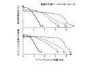
アルミニウム合金板の溶融部,溶融アルミニウムめっき鋼板の熱影響部のナゲットの半径方向に沿った量的変化は、ナゲットの中心部ほど高温に長時間保持されていることを意味する。ナゲット中心部の加熱状態は、スポット溶接に用いる電極の先端アールによって大きな影響を受ける。そこで、先端アールが種々異なる電極を用いたスポット溶接で形成されたナゲットについて、ナゲット中心からの距離と最高到達温度との関係を調査した。 The quantitative change along the radial direction of the nugget in the molten part of the aluminum alloy plate and the heat-affected part of the hot-dip aluminum-plated steel sheet means that the center part of the nugget is held at a higher temperature for a longer time. The heating state of the nugget center is greatly affected by the tip radius of the electrode used for spot welding. Therefore, the relationship between the distance from the center of the nugget and the maximum temperature was investigated for nuggets formed by spot welding using electrodes with different tip radiuses.
調査結果は、先端アールの小さな電極を使用するほどナゲット中心から離れるに従って最高到達温度が急激に低下することを示している(図3上)。Al-Fe二元合金層の生成量も、ナゲットの半径方向に関する温度分布に対応し、先端アールの小さな電極を使用するほどAl-Fe二元合金層の生成量がナゲットの半径方向に沿って急激に減少する傾向が示された(図3下)。Al-Fe二元合金層の生成量に及ぼすナゲットの先端アールの影響から、適正な先端アールをもつ電極を用いてスポット溶接することにより、ナゲット中心部からナゲット外周部にかけて合金層消失域が形成されることが判る。 The results of the investigation show that the maximum temperature reached abruptly decreases with increasing distance from the center of the nugget as the electrode with a smaller tip radius is used (upper part of FIG. 3). The generation amount of the Al—Fe binary alloy layer also corresponds to the temperature distribution in the radial direction of the nugget, and the generation amount of the Al—Fe binary alloy layer increases along the radial direction of the nugget as an electrode with a smaller tip radius is used. A tendency to decrease rapidly was shown (bottom of FIG. 3). From the influence of the nugget tip radius on the amount of Al-Fe binary alloy layer produced, spot welding using an electrode with an appropriate tip radius forms an alloy layer disappearance zone from the nugget center to the nugget outer periphery. It can be seen that
C:0.04質量%,Si:0.01質量%,Mn:0.20質量%,P:0.01質量%,S:0.007質量%,Al:0.010質量%,N:120ppmを含む板厚1.0mmの冷延鋼板にSi:9.2質量%,Fe:1.8質量%を含む膜厚:20μmの溶融アルミニウムめっき層を形成した後、450℃×15時間のポスト加熱で下地鋼/めっき層界面にNを5原子%濃化させた溶融アルミニウムめっき鋼板を一方の被接合材に使用した。該溶融アルミニウムめっき鋼板では、Al−10.9質量%Si−35.8質量%FeのAl−Fe−Si三元合金層が下地鋼/めっき層界面に生成していた。 C: 0.04 mass%, Si: 0.01 mass%, Mn: 0.20 mass%, P: 0.01 mass%, S: 0.007 mass%, Al: 0.010 mass%, N: After forming a hot-dip aluminum plating layer of Si: 9.2 mass% and Fe: 1.8 mass% on a cold rolled steel sheet with a thickness of 1.0 mm containing 120 ppm: 20 μm, 450 ° C. × 15 hours A hot-dip aluminized steel sheet in which 5 atomic% of N was concentrated at the base steel / plated layer interface by post heating was used as one material to be joined. In the hot dip galvanized steel sheet, an Al—Fe—Si ternary alloy layer of Al-10.9% by mass Si-35.8% by mass Fe was formed at the base steel / plated layer interface.
相手材には、Si:0.11質量%,Fe:0.25質量%,Mg:5.52質量%,Cu:0.35質量%,Cr:0.02質量%,Zn:0.01質量%,残部Alで板厚1.0mmのアルミニウム合金板を使用した。
溶融アルミニウムめっき鋼板,アルミニウム合金板から切り出した試験片を脱脂・洗浄した後、重ね合わせてスポット溶接用の電極間に挟み込み、3kNの圧力を加えた。先端アールが4,10,75,200mmと異なる4種類の銅合金チップ(径:16mm)を電極3に使用し、最大溶接電流25kA,周波数60Hz,サイクル数12でスポット溶接した。
The counterpart materials were Si: 0.11 mass%, Fe: 0.25 mass%, Mg: 5.52 mass%, Cu: 0.35 mass%, Cr: 0.02 mass%, Zn: 0.01 An aluminum alloy plate having a thickness of 1.0 mm with a mass% and the balance Al was used.
A test piece cut out from a hot-dip aluminum-plated steel plate or aluminum alloy plate was degreased and washed, and then overlapped and sandwiched between electrodes for spot welding, and a pressure of 3 kN was applied. Four types of copper alloy chips (diameter: 16 mm) having different tip radiuses of 4, 10, 75, and 200 mm were used for the
スポット溶接で形成された接合界面を観察し、Al-Fe二元合金層,Al-Fe-Si三元合金層の生成状況を調査した。接合界面の観察結果を画像処理し、ナゲット中心から1mmごとの同心円を横切るAl-Fe二元合金層からAl-Fe二元合金層の線分比を算出した。算出した線分比でAl-Fe二元合金層の生成量を評価した。
図3に示すように、電極先端のアールが小さくなるほど最高到達温度の低いナゲット外周部が幅広くなり、それに伴ってAl-Fe二元合金層の生成域がナゲット中心部に限られた。先端アールが4mmと小さな電極を用いてスポット溶接した場合、ナゲット中心から2mm以上のナゲット外周側にAl-Fe二元合金層がほとんど生成しておらず、一部にAl-Fe-Si三元合金層が検出される合金層消失域となっていた。
The bonding interface formed by spot welding was observed, and the formation state of the Al—Fe binary alloy layer and the Al—Fe—Si ternary alloy layer was investigated. The observation result of the joint interface was image-processed, and the line segment ratio of the Al—Fe binary alloy layer was calculated from the Al—Fe binary alloy layer crossing a concentric circle every 1 mm from the nugget center. The production amount of the Al—Fe binary alloy layer was evaluated based on the calculated line segment ratio.
As shown in FIG. 3, the outer periphery of the nugget with the lowest maximum temperature becomes wider as the radius of the electrode tip becomes smaller, and accordingly, the generation region of the Al—Fe binary alloy layer is limited to the center of the nugget. When spot welding is performed using an electrode with a tip radius as small as 4 mm, almost no Al—Fe binary alloy layer is formed on the outer side of the
他方、先端アールが200mmと大きな電極を使用した場合、溶接電流の電極中心への集中が少ないため、Al-Fe二元合金層の線分比が98%と高い値を示した。
次いで、各接合構造体から試験片を切り出し、剪断試験によって継手強度を測定した。先端アール:200mmの電極を用いたスポット溶接で得られた接合構造体では、2.2kNの剪断力で溶融アルミニウムめっき鋼板からアルミニウム材料に分離し、溶融アルミニウムめっき鋼板の接合部にアルミニウム材料の痕跡が検出されなかった。他方、先端アールが小さい電極を用いたスポット溶接で得られた接合構造体では、2.6kN以上の高い剪断強度を呈し、母材破断するものもあった。(表1)
On the other hand, when an electrode having a large tip radius of 200 mm was used, the concentration of the welding current at the electrode center was small, and the line segment ratio of the Al—Fe binary alloy layer was as high as 98%.
Subsequently, a test piece was cut out from each joint structure, and joint strength was measured by a shear test. Tip R: In a joint structure obtained by spot welding using an electrode of 200 mm, the aluminum material is separated from the molten aluminum plated steel plate with a shearing force of 2.2 kN, and the trace of the aluminum material is present at the joint of the molten aluminum plated steel plate. Was not detected. On the other hand, some joint structures obtained by spot welding using an electrode having a small tip radius exhibit a high shear strength of 2.6 kN or more and break the base material. (Table 1)

C:0.05質量%,Si:0.1質量%,Mn:0.25質量%,P:0.012質量%,S:0.006質量%,Al:0.006質量%を含む冷延鋼板を溶融アルミニウムめっきした。溶融アルミニウムめっきでは、溶融アルミニウムめっき層のSi含有量が1.8質量%,5.5質量%,9.5質量%の三水準、Fe含有量が0.2〜0.3質量%,0.8〜0.9質量%,1.8〜2.2質量%,4.2〜4.6質量%,5.7〜6.1質量%の五水準、厚みが25〜30μmとなるように溶融アルミニウム浴の組成,溶融めっき条件を調整した。 C: 0.05% by mass, Si: 0.1% by mass, Mn: 0.25% by mass, P: 0.012% by mass, S: 0.006% by mass, Al: 0.006% by mass The rolled steel sheet was hot dip aluminum plated. In hot dip aluminum plating, the Si content of the hot dip aluminum plating layer is three levels of 1.8 mass%, 5.5 mass%, and 9.5 mass%, and the Fe content is 0.2 to 0.3 mass%, 0. Five levels of 0.8-0.9% by mass, 1.8-2.2% by mass, 4.2-4.6% by mass, 5.7-6.1% by mass, and a thickness of 25-30 μm. The composition of the molten aluminum bath and the conditions of the hot dipping were adjusted.
相手材には、Si:1.21質量%,Fe:0.37質量%,Mg:0.7質量%,Cu:0.02質量%,Zn:0.01質量%,Al:残部で板厚1.0mmのアルミニウム合金板を使用した。
溶融アルミニウムめっき鋼板,アルミニウム合金板から切り出した試験片を脱脂・洗浄した後、交流スポット溶接機(60Hz)でスポット溶接した。溶接条件としては、先端アール:75mmの銅合金チップを電極に用い、溶接電流を21kA,通電時間を12サイクルに設定した。
The other material is Si: 1.21% by mass, Fe: 0.37% by mass, Mg: 0.7% by mass, Cu: 0.02% by mass, Zn: 0.01% by mass, Al: remaining plate An aluminum alloy plate having a thickness of 1.0 mm was used.
A test piece cut out from a hot-dip aluminum-plated steel plate or aluminum alloy plate was degreased and washed, and then spot welded with an AC spot welder (60 Hz). As welding conditions, a tip end radius: a 75 mm copper alloy tip was used as an electrode, the welding current was set to 21 kA, and the energization time was set to 12 cycles.
作製された接合構造体の接合強度を引張り剪断試験及び十字引張試験で測定した。
表2の試験結果にみられるように、溶融アルミニウムめっき層のSi,Fe濃度が適正範囲(Si:3〜12質量%,Fe:0.5〜5質量%)に維持されると、引張り剪断強度:2.4kN以上,十字引張り強度:1.3kN以上と高い接合強度をもつ接合構造体が得られた。
The joint strength of the produced joint structure was measured by a tensile shear test and a cross tension test.
As can be seen from the test results in Table 2, when the Si and Fe concentrations in the molten aluminum plating layer are maintained within the appropriate ranges (Si: 3 to 12% by mass, Fe: 0.5 to 5% by mass), tensile shear A bonded structure having a high bonding strength of strength: 2.4 kN or more and cross tensile strength: 1.3 kN or more was obtained.
他方、溶融アルミニウムめっき層のSi,Fe濃度が低いとAl-Fe二元合金層の線分率が高くなり、引張り剪断強度:2.4kN以下,十字引張り強度:0.9kNと接合強度が低下した。引張試験で破断した接合界面を観察すると、連続的な割れが中心部まで合金層間に発生しており、接合界面全域にあるAl-Fe二元合金層によって接合強度が低下することが確認された。 On the other hand, when the Si and Fe concentrations in the hot-dip aluminum plating layer are low, the line segment ratio of the Al—Fe binary alloy layer is high, and the tensile shear strength is 2.4 kN or less, and the cross tensile strength is 0.9 kN. did. When observing the fractured interface in the tensile test, it was confirmed that continuous cracking occurred between the alloy layers up to the center, and the bonding strength was reduced by the Al-Fe binary alloy layer in the entire area of the interface. .
また、溶融アルミニウムめっき層と下地鋼との界面にあるAl‐Fe‐Si三元合金層の厚さの影響を調査するため、Si:9.5質量%,Fe:2.2質量%の溶融アルミニウムめっき浴を用いて製造された溶融アルミニウムめっき鋼板について、溶融めっき後の冷却速度を-40℃/秒以上と大きくすることによりAl‐Fe‐Si三元合金層の厚みを0.08μmに調整した。この場合、Al‐Fe‐Si三元合金層の厚みが目標値0.1μmに達していないので、スポット溶接時にAl‐Fe二元合金層が生成しやすく、結果として引張り剪断強度:2.6kN,十字引張り強度:1.1kNと接合強度が低下する傾向にあった。 Also, in order to investigate the effect of the thickness of the Al-Fe-Si ternary alloy layer at the interface between the molten aluminum plating layer and the base steel, the melting of Si: 9.5 mass%, Fe: 2.2 mass% Adjusting the thickness of Al-Fe-Si ternary alloy layer to 0.08μm by increasing the cooling rate after hot dipping to -40 ℃ / sec or more for hot dipped aluminum plated steel sheet manufactured using aluminum plating bath did. In this case, since the thickness of the Al—Fe—Si ternary alloy layer does not reach the target value of 0.1 μm, an Al—Fe binary alloy layer is likely to be formed during spot welding, resulting in a tensile shear strength of 2.6 kN. The cross tensile strength was 1.1 kN, and the joint strength tended to decrease.
以上に説明したように、先端にアールをつけた電極を用いて溶融アルミニウムめっき鋼板,アルミニウム材料をスポット溶接するとき、電極中心から周辺に向けた接合部の温度分布がAl-Fe二元合金層の生成抑制に効果的な温度勾配をもち、Al−Fe二元合金層のない合金層消失域をもつ接合界面が形成される。合金層消失域の一部に、継手強度の向上に有効なAl-Fe-Si三元合金層が残存・生成することもある。そのため、鋼材,アルミニウム材料が強固に接合され、アルミニウム材料,鋼材の長所を活かした接合構造体として、車輌構造体,熱交換器等、種々の構造部材に使用される。 As described above, when spot welding a hot-dip aluminized steel sheet and aluminum material using an electrode with a rounded tip, the temperature distribution of the joint from the center of the electrode toward the periphery is an Al-Fe binary alloy layer. A bonding interface having a temperature gradient effective for suppressing the formation of the alloy layer and having an alloy layer disappearing region without the Al—Fe binary alloy layer is formed. An Al—Fe—Si ternary alloy layer that is effective in improving joint strength may remain and be generated in a part of the alloy layer disappearance region. For this reason, steel materials and aluminum materials are firmly joined and used as various structural members such as vehicle structures and heat exchangers as joint structures utilizing the advantages of aluminum materials and steel materials.
1:溶融アルミニウムめっき鋼板 2:アルミニウム材料 3:電極 4:溶融アルミニウムめっき層 5:下地鋼 6:Al-Fe-Si三元合金層 7:Al-Fe二元合金層 8:ナゲット 9:合金層消失域 1: Hot dip galvanized steel sheet 2: Aluminum material 3: Electrode 4: Hot dip aluminum plating layer 5: Base steel 6: Al—Fe—Si ternary alloy layer 7: Al—Fe binary alloy layer 8: Nugget 9: Alloy layer Vanishing zone
Claims (1)
Priority Applications (1)
| Application Number | Priority Date | Filing Date | Title |
|---|---|---|---|
| JP2004139286A JP4476016B2 (en) | 2004-05-10 | 2004-05-10 | Manufacturing method of steel / aluminum joint structure |
Applications Claiming Priority (1)
| Application Number | Priority Date | Filing Date | Title |
|---|---|---|---|
| JP2004139286A JP4476016B2 (en) | 2004-05-10 | 2004-05-10 | Manufacturing method of steel / aluminum joint structure |
Publications (2)
| Publication Number | Publication Date |
|---|---|
| JP2005319481A JP2005319481A (en) | 2005-11-17 |
| JP4476016B2 true JP4476016B2 (en) | 2010-06-09 |
Family
ID=35467144
Family Applications (1)
| Application Number | Title | Priority Date | Filing Date |
|---|---|---|---|
| JP2004139286A Active JP4476016B2 (en) | 2004-05-10 | 2004-05-10 | Manufacturing method of steel / aluminum joint structure |
Country Status (1)
| Country | Link |
|---|---|
| JP (1) | JP4476016B2 (en) |
Families Citing this family (9)
| Publication number | Priority date | Publication date | Assignee | Title |
|---|---|---|---|---|
| EP1987904B1 (en) * | 2006-02-23 | 2015-08-12 | Kabushiki Kaisha Kobe Seiko Sho | Joint product between steel product and aluminum material |
| JP4860537B2 (en) * | 2007-04-10 | 2012-01-25 | 新日本製鐵株式会社 | Automotive parts with excellent corrosion resistance at joints |
| JP5231371B2 (en) * | 2009-10-13 | 2013-07-10 | 本田技研工業株式会社 | Resistance welding method |
| JP5572046B2 (en) * | 2010-09-13 | 2014-08-13 | 株式会社神戸製鋼所 | Dissimilar material joining method |
| KR101253893B1 (en) * | 2010-12-27 | 2013-04-16 | 포스코강판 주식회사 | Aluminium coated steel sheet having excellent in oxidization resistence and heat resistence |
| JP5873465B2 (en) * | 2013-08-14 | 2016-03-01 | 日新製鋼株式会社 | Al-coated steel sheet excellent in total reflection characteristics and corrosion resistance and its manufacturing method |
| KR101575473B1 (en) | 2014-05-16 | 2015-12-10 | 우양에이치씨(주) | Aluminum Coating Device And Method Thereof |
| US10625367B2 (en) * | 2016-04-08 | 2020-04-21 | GM Global Technology Operations LLC | Method of resistance spot welding aluminum to steel |
| WO2020208399A1 (en) * | 2019-04-09 | 2020-10-15 | Arcelormittal | Assembly of an aluminium component and of a press hardened steel part having an alloyed coating comprising silicon, iron, zinc, optionally magnesium, the balance being aluminum |
-
2004
- 2004-05-10 JP JP2004139286A patent/JP4476016B2/en active Active
Also Published As
| Publication number | Publication date |
|---|---|
| JP2005319481A (en) | 2005-11-17 |
Similar Documents
| Publication | Publication Date | Title |
|---|---|---|
| Su et al. | Influence of alloy elements on microstructure and mechanical property of aluminum–steel lap joint made by gas metal arc welding | |
| US20170304958A1 (en) | Aluminum welding filler metal, casting and wrought metal alloy | |
| JP4911977B2 (en) | Steel / aluminum joint structure | |
| JPWO2014126246A1 (en) | Solid wire for gas shielded arc welding, gas shielded arc welding metal, welded joint, welded member, welding method, and method of manufacturing welded joint | |
| JP7124991B1 (en) | Welded joints and auto parts | |
| JP7124992B1 (en) | Welded joints and auto parts | |
| JP4476016B2 (en) | Manufacturing method of steel / aluminum joint structure | |
| JP5098792B2 (en) | Dissimilar metal joining method of magnesium alloy and steel | |
| JP2011036918A (en) | Method for joining different materials and filler metal therefor | |
| JPWO2020130079A1 (en) | Spot welded member | |
| JP2006224127A (en) | Method for manufacturing steel/aluminum joined structure | |
| EP3137253A1 (en) | A ductile boron bearing nickel based welding material | |
| JP7003806B2 (en) | Joined structure and its manufacturing method | |
| Venukumar et al. | TIG arc welding-brazing of dissimilar metals-an overview | |
| JP4640995B2 (en) | Steel plate for brazing joint with aluminum material, joining method and joint using the steel plate | |
| JP4280670B2 (en) | Steel / aluminum joint structure | |
| JP5059455B2 (en) | Steel plate for brazing joint with aluminum material, joining method and joint using the steel plate | |
| KR102061470B1 (en) | MIG brazing method, manufacturing method of overlap joint member, and overlap joint member | |
| JP2014172053A (en) | Manufacturing method of weld joint | |
| JP4280671B2 (en) | Steel / aluminum joint structure | |
| JP4857013B2 (en) | Bonding structure | |
| JP7021591B2 (en) | Joined structure and its manufacturing method | |
| JP7047543B2 (en) | Joined structure and its manufacturing method | |
| JP7003805B2 (en) | Joined structure and its manufacturing method | |
| JP4452205B2 (en) | Steel plate for brazing joint with aluminum material, joining method and joint using the steel plate |
Legal Events
| Date | Code | Title | Description |
|---|---|---|---|
| RD04 | Notification of resignation of power of attorney |
Free format text: JAPANESE INTERMEDIATE CODE: A7424 Effective date: 20070308 |
|
| A621 | Written request for application examination |
Free format text: JAPANESE INTERMEDIATE CODE: A621 Effective date: 20070425 |
|
| A977 | Report on retrieval |
Free format text: JAPANESE INTERMEDIATE CODE: A971007 Effective date: 20090805 |
|
| A131 | Notification of reasons for refusal |
Free format text: JAPANESE INTERMEDIATE CODE: A131 Effective date: 20090818 |
|
| A521 | Request for written amendment filed |
Free format text: JAPANESE INTERMEDIATE CODE: A523 Effective date: 20091019 |
|
| A131 | Notification of reasons for refusal |
Free format text: JAPANESE INTERMEDIATE CODE: A131 Effective date: 20100105 |
|
| A521 | Request for written amendment filed |
Free format text: JAPANESE INTERMEDIATE CODE: A523 Effective date: 20100105 |
|
| TRDD | Decision of grant or rejection written | ||
| A01 | Written decision to grant a patent or to grant a registration (utility model) |
Free format text: JAPANESE INTERMEDIATE CODE: A01 Effective date: 20100309 |
|
| A01 | Written decision to grant a patent or to grant a registration (utility model) |
Free format text: JAPANESE INTERMEDIATE CODE: A01 |
|
| A61 | First payment of annual fees (during grant procedure) |
Free format text: JAPANESE INTERMEDIATE CODE: A61 Effective date: 20100309 |
|
| R150 | Certificate of patent or registration of utility model |
Ref document number: 4476016 Country of ref document: JP Free format text: JAPANESE INTERMEDIATE CODE: R150 Free format text: JAPANESE INTERMEDIATE CODE: R150 |
|
| FPAY | Renewal fee payment (event date is renewal date of database) |
Free format text: PAYMENT UNTIL: 20130319 Year of fee payment: 3 |
|
| FPAY | Renewal fee payment (event date is renewal date of database) |
Free format text: PAYMENT UNTIL: 20160319 Year of fee payment: 6 |
|
| R250 | Receipt of annual fees |
Free format text: JAPANESE INTERMEDIATE CODE: R250 |
|
| R250 | Receipt of annual fees |
Free format text: JAPANESE INTERMEDIATE CODE: R250 |
|
| R250 | Receipt of annual fees |
Free format text: JAPANESE INTERMEDIATE CODE: R250 |
|
| R250 | Receipt of annual fees |
Free format text: JAPANESE INTERMEDIATE CODE: R250 |
|
| R250 | Receipt of annual fees |
Free format text: JAPANESE INTERMEDIATE CODE: R250 |
|
| R250 | Receipt of annual fees |
Free format text: JAPANESE INTERMEDIATE CODE: R250 |
|
| R250 | Receipt of annual fees |
Free format text: JAPANESE INTERMEDIATE CODE: R250 |
|
| S111 | Request for change of ownership or part of ownership |
Free format text: JAPANESE INTERMEDIATE CODE: R313115 |
|
| R350 | Written notification of registration of transfer |
Free format text: JAPANESE INTERMEDIATE CODE: R350 |
|
| R250 | Receipt of annual fees |
Free format text: JAPANESE INTERMEDIATE CODE: R250 |
|
| R250 | Receipt of annual fees |
Free format text: JAPANESE INTERMEDIATE CODE: R250 |