JP4474190B2 - Method and apparatus for mounting rotating member - Google Patents
Method and apparatus for mounting rotating member Download PDFInfo
- Publication number
- JP4474190B2 JP4474190B2 JP2004120950A JP2004120950A JP4474190B2 JP 4474190 B2 JP4474190 B2 JP 4474190B2 JP 2004120950 A JP2004120950 A JP 2004120950A JP 2004120950 A JP2004120950 A JP 2004120950A JP 4474190 B2 JP4474190 B2 JP 4474190B2
- Authority
- JP
- Japan
- Prior art keywords
- shaft
- ring
- hyperboloid
- curvature
- hourglass
- Prior art date
- Legal status (The legal status is an assumption and is not a legal conclusion. Google has not performed a legal analysis and makes no representation as to the accuracy of the status listed.)
- Expired - Fee Related
Links
Images


Classifications
-
- H—ELECTRICITY
- H01—ELECTRIC ELEMENTS
- H01J—ELECTRIC DISCHARGE TUBES OR DISCHARGE LAMPS
- H01J35/00—X-ray tubes
- H01J35/02—Details
- H01J35/04—Electrodes ; Mutual position thereof; Constructional adaptations therefor
- H01J35/08—Anodes; Anti cathodes
- H01J35/10—Rotary anodes; Arrangements for rotating anodes; Cooling rotary anodes
- H01J35/101—Arrangements for rotating anodes, e.g. supporting means, means for greasing, means for sealing the axle or means for shielding or protecting the driving
-
- F—MECHANICAL ENGINEERING; LIGHTING; HEATING; WEAPONS; BLASTING
- F16—ENGINEERING ELEMENTS AND UNITS; GENERAL MEASURES FOR PRODUCING AND MAINTAINING EFFECTIVE FUNCTIONING OF MACHINES OR INSTALLATIONS; THERMAL INSULATION IN GENERAL
- F16C—SHAFTS; FLEXIBLE SHAFTS; ELEMENTS OR CRANKSHAFT MECHANISMS; ROTARY BODIES OTHER THAN GEARING ELEMENTS; BEARINGS
- F16C17/00—Sliding-contact bearings for exclusively rotary movement
- F16C17/02—Sliding-contact bearings for exclusively rotary movement for radial load only
-
- F—MECHANICAL ENGINEERING; LIGHTING; HEATING; WEAPONS; BLASTING
- F16—ENGINEERING ELEMENTS AND UNITS; GENERAL MEASURES FOR PRODUCING AND MAINTAINING EFFECTIVE FUNCTIONING OF MACHINES OR INSTALLATIONS; THERMAL INSULATION IN GENERAL
- F16C—SHAFTS; FLEXIBLE SHAFTS; ELEMENTS OR CRANKSHAFT MECHANISMS; ROTARY BODIES OTHER THAN GEARING ELEMENTS; BEARINGS
- F16C27/00—Elastic or yielding bearings or bearing supports, for exclusively rotary movement
- F16C27/02—Sliding-contact bearings
-
- H—ELECTRICITY
- H01—ELECTRIC ELEMENTS
- H01J—ELECTRIC DISCHARGE TUBES OR DISCHARGE LAMPS
- H01J9/00—Apparatus or processes specially adapted for the manufacture, installation, removal, maintenance of electric discharge tubes, discharge lamps, or parts thereof; Recovery of material from discharge tubes or lamps
- H01J9/02—Manufacture of electrodes or electrode systems
- H01J9/18—Assembling together the component parts of electrode systems
-
- H—ELECTRICITY
- H01—ELECTRIC ELEMENTS
- H01J—ELECTRIC DISCHARGE TUBES OR DISCHARGE LAMPS
- H01J2235/00—X-ray tubes
- H01J2235/10—Drive means for anode (target) substrate
- H01J2235/1046—Bearings and bearing contact surfaces
-
- H—ELECTRICITY
- H01—ELECTRIC ELEMENTS
- H01J—ELECTRIC DISCHARGE TUBES OR DISCHARGE LAMPS
- H01J2235/00—X-ray tubes
- H01J2235/10—Drive means for anode (target) substrate
- H01J2235/1046—Bearings and bearing contact surfaces
- H01J2235/1053—Retainers or races
-
- Y—GENERAL TAGGING OF NEW TECHNOLOGICAL DEVELOPMENTS; GENERAL TAGGING OF CROSS-SECTIONAL TECHNOLOGIES SPANNING OVER SEVERAL SECTIONS OF THE IPC; TECHNICAL SUBJECTS COVERED BY FORMER USPC CROSS-REFERENCE ART COLLECTIONS [XRACs] AND DIGESTS
- Y10—TECHNICAL SUBJECTS COVERED BY FORMER USPC
- Y10T—TECHNICAL SUBJECTS COVERED BY FORMER US CLASSIFICATION
- Y10T403/00—Joints and connections
- Y10T403/70—Interfitted members
- Y10T403/7047—Radially interposed shim or bushing
- Y10T403/7061—Resilient
Landscapes
- Engineering & Computer Science (AREA)
- General Engineering & Computer Science (AREA)
- Mechanical Engineering (AREA)
- Manufacturing & Machinery (AREA)
- Rolls And Other Rotary Bodies (AREA)
- Sliding-Contact Bearings (AREA)
- Vibration Prevention Devices (AREA)
- Manufacture Of Motors, Generators (AREA)
- Apparatus For Radiation Diagnosis (AREA)
- X-Ray Techniques (AREA)
Description
本発明は、回転部材を装着する方法及び装置に関する。具体的には、本発明は、放射線源に関し、さらに具体的には、X線管での回転式アノードの装着、及び上記装置の部品の製法に関する。回転式アノード管は、主としてマンモグラフィに用いられるX線放出管であるが、他の放射線分野、特に断層像密度測定法(tomodensitometry)での利用も想到され得る。 The present invention relates to a method and apparatus for mounting a rotating member. In particular, the present invention relates to radiation sources, and more specifically to the mounting of a rotating anode in an X-ray tube and a method for manufacturing the components of the apparatus. The rotary anode tube is an X-ray emission tube mainly used for mammography, but can be conceived for use in other radiation fields, particularly in tomographic density measurement.
マンモグラフィでは、検査条件として、患者が自分の乳房を乳房載置台に配置する必要がある。X線放出装置は一般的には、乳房載置台を支持している垂直支柱に設けられており、患者の頭部の近くに配置される。このように近接していると、電気系統の設置に特に厳しい制約が加わるのみならず、ただでさえ負担の大きい検査時に患者を煩らわせないように、X線管が振動しないことが要求される。これらの振動は音がうるさい。一般的には、振動は特に、管の被覆が金属製であり被覆自体が振動に敏感であるため生じる。 In mammography, as an examination condition, a patient needs to place his / her breast on a breast mount. The X-ray emission device is generally provided on a vertical column supporting a breast mounting table and is arranged near the patient's head. Such close proximity not only places particularly severe restrictions on the installation of the electrical system, but also requires that the X-ray tube does not vibrate so as not to bother the patient during examinations that are burdensome. The These vibrations are noisy. In general, vibrations occur particularly because the tube coating is metallic and the coating itself is sensitive to vibration.
実際には、回転式アノードを備えたX線管は、高速回転するアノードを有している。アノードは、一方の面ではカソードに対面し、他方の面では、真空密閉されているが放出されたX線の通過は可能な窓に対面するように配置されている。アノードの回転は、軸受で動作するロータによって駆動される。ロータは、ロータが固定接合されている回転式アノードを駆動する。しかしながら、この回転部材を均衡させようとするあらゆる試みにも拘わらず、不均衡が生じて管全体を振動させる一因となる。シャフトは両端で固定されることにより管に固定されている。従って、シャフトは片側では第一の構造すなわち管の被覆の第一の部分に固定され、他の側では第二の構造すなわち被覆の第二の部分に固定される。次いで、これら二つの構造を互いに結合する。これらの構造の結合が堅固であると、かかるアセンブリはシャフトの把持に不静定(hyperstatic)状態を招き、機械的なレベルで破壊を伴うため許容できない。この欠点を克服するために、ある程度の自由度を許容する環を用いて、シャフトの一端を原則として最も軽量で且つ/又は最も剛性の低い構造形式である構造に装着する。用いられる環は一般的には、回転かご(squirrel-cage)形状を有しており、弾力性を有するが、再利用できないのが欠点である。実際に、シャフト端部の挿入の前に環を構造に装着するときに環を圧入しなければならないため、環が変形する。さらに、環の挿入自体が、組立時にかなりの力を加えることを必要とする。
これらの環の有用性は、不静定状態に関連する問題を解決すること、またさらにアノードの発熱に起因する膨脹を許容することにある。しかしながら、環は振動の問題を解決しておらず、振動は依然として患者にとっての様々な問題の原因となっており、また取得される放射線画像の精度を損なう可能性もある。 The usefulness of these rings is to solve the problems associated with the unsteady state and also to allow expansion due to the exotherm of the anode. However, the ring does not solve the problem of vibration, which still causes various problems for the patient and can also impair the accuracy of the acquired radiographic image.
本発明の一実施形態は、振動の問題及び環の再利用に関わる。本発明の一実施形態では、環は鼓(ツヅミ、原語:diabolo)形の環である。鼓形環は、端部の頭冠によって構造の収容部内に支持される。環は、鼓形部材の中央部が狭まっていることにより鼓形部材の内部でシャフトを把持する。開いた形状の鼓形部材を製造することによる一実施形態では、シャフトの端部を受ける凹部の製造時公差の値に合わせて環を構成することができる。従って、環の挿入には最早過大な力での圧入は必要とされない。結果として、環を再利用することができる。本発明の一実施形態では、鼓形部材は双曲面形状である。 One embodiment of the present invention involves vibration problems and ring reuse. In one embodiment of the present invention, the ring is a drum-shaped ring. The hourglass ring is supported in the housing of the structure by an end crown. The ring grips the shaft inside the hourglass member by narrowing the central part of the hourglass member. In one embodiment by manufacturing an open hourglass, the ring can be configured to match the manufacturing tolerance of the recess that receives the end of the shaft. Therefore, press-fitting with an excessive force is no longer required for inserting the ring. As a result, the ring can be reused. In one embodiment of the present invention, the hourglass-shaped member has a hyperboloid shape.
また、本発明の一実施形態は、製造経費を最低限まで抑えるような鼓形環の製法に関する。本方法の一実施形態では、鼓形形状は双曲面形状である。 In addition, an embodiment of the present invention relates to a method for making a hourglass ring that minimizes manufacturing costs. In one embodiment of the method, the hourglass shape is a hyperboloid shape.
また、本発明の一実施形態は、X線管に回転式アノードを装着する装置であって、該装置は、第一の構造において、凹部と、凹部に収容されている環とを備えており、回転式アノードのシャフトの一端がこの環に挿入され、環は、シャフト軸の周りでの回転によって得られる鼓形形状を含んでいる。 One embodiment of the present invention is an apparatus for mounting a rotary anode on an X-ray tube, and the apparatus includes a recess and a ring accommodated in the recess in the first structure. One end of the shaft of the rotary anode is inserted into this ring, which contains the hourglass shape obtained by rotation around the shaft axis.
また、本発明の一実施形態は、鼓形部材の製法であって、円筒から鼓形部材を形成する工程と、鼓形部材の一面に縦桟(beam)を形成する工程とを備えており、縦桟は傾斜させることができる。 Moreover, one embodiment of the present invention is a method of manufacturing a hourglass-shaped member, and includes a step of forming a hourglass-shaped member from a cylinder and a step of forming a vertical beam (beam) on one surface of the hourglass-shaped member. The vertical beam can be tilted.
本発明の実施形態は、以下の説明及び添付図面からさらに明確に理解されよう。図面は単に例を掲げるものであって、本発明の範囲を制限するものではない。 Embodiments of the present invention will be more clearly understood from the following description and the accompanying drawings. The drawings are merely examples and do not limit the scope of the invention.
図1は、X線管内でアノード1のような回転部材を装着する装置を示す。X線管自体は図示されていない。図示のように、回転式アノード1は、シャフト3の周りに設けられているモータ式ロータ(好ましくはブラシレス電動モータ)に堅固に装着されている。シャフト3は、固定された第一の構造4においては例えば堅固に装着されており、第二の構造6においては環5によって装着されている。ロータ2及び回転式アノード1は、シャフト3に一致整列した回転軸7を中心として回転する。本例では、シャフト3は公知の手段で構造4に堅固に固定されている。例えば、シャフト3はねじで構造にねじ留めされる。構造4及び6はさらに、互いに対して固定されるようにX線管の被覆に連結されている。実際には、これら二つの構造の一方、本例では構造4は質量が大きい。他方の構造すなわち構造6は相対的に軽量である。いずれにせよ、構造4は、音響源を生成する振動力に対して構造6ほど敏感でない。この形式のアセンブリは、シャフト3を介して構造6に伝達される振動を生じ、次いでこの振動は環5の存在にも拘わらずうるさい騒音を発生する。
FIG. 1 shows an apparatus for mounting a rotating member such as an anode 1 in an X-ray tube. The X-ray tube itself is not shown. As shown in the figure, the rotary anode 1 is firmly attached to a motor type rotor (preferably a brushless electric motor) provided around the
本発明の一実施形態では、環5は、シャフト3の軸7である軸を中心とした回転によって得られる鼓形形状を有している。この形状を図5及び図6に示す。かかる軸は、第一の頭冠8と第二の頭冠9とを含んでおり、両方とも円筒形であって、母線はシャフト3の軸7に平行である。これらの頭冠8及び9は、一組の縦桟によって互いに連結されており、縦桟は本実施形態では参照番号10に示すように傾斜している。但し、傾斜していない縦桟を設けることも可能であるが、後述するように、縦桟が傾斜している方が、環が用いられているときの環の健全性をより十分に保証する。次いで、回転要素を支持しているシャフト3と、管の被覆の構造6との間に鼓形部材を装着すると、所望の騒音低減が得られる。
In one embodiment of the present invention, the
本発明の鼓形環を製造するために幾つかの方法が可能である。例として、環の寸法及び形状を10(A) 〜図10(C)を参照しながら後に詳述する。図2は、例えば金属若しくは合金製、又は場合によっては複合材料製の薄板のようなプレート11を示しており、プレート11には真直な縦穴12が形成されて、縦桟13が縦穴の各々の間で個別形成されることを可能にしている。縦穴12及び縦桟13は直線状であって、本例では、縦桟13を互いに連結している2本の横桟(lintel)14及び15の方向に対して直角を成して配向している。縦穴12は、レーザ、マトリクス型押抜加工、エッチング又は他の類似の方法によって図示の態様で切断することができる。
Several methods are possible to produce the hourglass ring of the present invention. As an example, the dimensions and shape of the ring will be described in detail later with reference to 10 (A) to FIG. 10 (C). FIG. 2 shows a
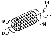
一旦、切断作業が行なわれたら、図3に示すように、縦穴12及び縦桟13の方向に平行な軸16に沿って配向した円筒形チャックの周りで丸めることによりプレート11を成形する。成形の後に、環を閉じるように横桟14及び15の両端を合わせてはんだ付けすることができる。以下では、環を開いたままにし得る実施形態を説明する。一旦、この円筒が形成されたら、図4(A)に示すように、縦穴12及び縦桟13の方向に平行な軸19を中心として、現時点で円形になっている横桟14及び15を互いに反対方向17及び18にそれぞれ回転させることにより、上述のようにして形成された環を捻転させる。得られる構造を図5及び図6に示す。同図では、横桟14及び15がそれぞれ頭冠8及び9の位置を占めている。捻転による方法は一解法であって他の等価な手法も可能である。
Once the cutting operation is performed, as shown in FIG. 3, the
開いた環を製造するためには、一方の横桟例えば横桟15に開口20(図2)を形成する。この開口は、中央縦穴21の延長線として形成することができる。軸16の周りで成形した後に、横桟15の両端22及び23を合わせて例えばはんだ付け等によって接合する一方で、横桟14の対応する両端は接合しない。
In order to manufacture an open ring, an opening 20 (FIG. 2) is formed in one side rail, for example, the
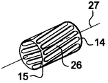
もう一つの手順は、矩形プレート11の利用ではなく平行四辺形プレート24の利用を含み得る。このプレート24では、横桟14及び15の法線に対して縦穴25が傾斜しており、縦桟26も傾斜している(図2の破線で示す)。次いで、横桟14及び15に垂直な軸16でのチャックの周りでの成形と同じ成形作業をプレート24に施す。これにより図4(B)に示す円筒環が形成され、ここでは縦桟26は円筒の母線と同じ配向にはなっておらず、円筒の辺縁に沿って螺旋状に成形されている。一旦、この円筒環が得られたら、成形用金型で応力を加えることができる。金型は全体的に、製造したい鼓形部材の雌形状を有するので、縦桟26は力を加えられて環の軸27の方向において環の内部に向かって屈曲する。
Another procedure may involve the use of a
一例では、横桟14及び15に対する縦桟26の傾斜は約50°±10°であってよい。図4(B)の環を収容する金型は、横桟14及び15の方向に直交する回転軸での回転によって得られる形状を有するものである。
In one example, the inclination of the
鼓形部材を製造するもう一つの実施形態では、図6に示すように例えば厚み28を有する肉厚の円筒から開始することも可能である。次いで、旋盤加工によって、鼓形部材から部分29を除去すると共に、鼓形部材の内部で頭冠8及び頭冠9から超過分の厚みを除去することにより、この肉厚円筒においてくびれを得ることが可能になる。一旦、鼓形部材がこのようにして形成されたら、特にレーザ切断によって頭冠8と頭冠9との間で縦桟10を個別形成することが可能である。
In another embodiment of manufacturing the hourglass, it is also possible to start with a thick cylinder, for example having a
但し、上述の金型成形法及び中抜き法は必ずしも双曲面形状の鼓形部材を形成するとは限らない。捻転法であれば無理なく形成することができる。 However, the above-described mold forming method and hollowing method do not necessarily form a hyperbolic hourglass-shaped member. A twisting method can be formed without difficulty.
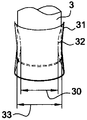
いずれの製法を用いるにせよ、鼓形部材の内部に縦桟10を配置することになる。これらの縦桟は、鼓形部材の内部の利用可能な空間を狭めると同時に、鼓形部材の両側に設けられて、径のより大きい円周を有する要素に取り付けられる。この意味で、図7及び図8は、シャフト3の挿入の前30及び後33のそれぞれについて対向面の内径を示している。図8で特に、実線は縦桟10の被覆の曲線31を示しており、破線32は挿入前の同じ被覆を示している。同図から分かるように、初期径30が拡大して、シャフト3を収容する直径33になる。曲率31と曲率32との差が、構造6(図1)においてシャフト3の端部を把持するときの弾性に相当する。
Whichever manufacturing method is used, the
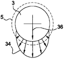
図9は、シャフト3が半径方向の力を受けたときに生ずる力のシヌソイド状振幅による図を示す。応力の分布34及び応力の評価から、環5の厚み、典型的にはプレート11又はプレート24の厚みを選択することが可能になる。また、軸7、19又は27に対する縦桟10の傾斜角を設定することも可能になる。さらに、縦桟13の数を設定することも可能になる。最後に、材料の性質、特にヤング率を設定することも可能になる。これらの要素はさらに、所望の彎曲差、すなわち曲率31と曲率32との間の差又は直径30と直径33との間の差の関数として決定される。
FIG. 9 shows a diagram with a sinusoidal amplitude of the force produced when the
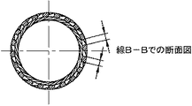
図10(A) 〜図10(E)は、双曲面形状を有する環の具体的な実施形態を示している。図10(B)は図10(A)の方向AAから見た断面図であり、図10(C)は方向BBから見た断面図である。図10(D)及び図10(E)は遠近図である。これらの図はすべて、環が20本の縦穴従って20本の縦桟を有している場合を示している。この環は一例では、上述の第三の方法によって得られており、図10(E)に示すように捻り角を50°±5°とした双曲面形状の縦桟を有している。角度は双曲面の回転軸に対して測定されている。一例では、環の内径は7.6mmであり公差は5/100であり、環の外径は9.5mmに等しく公差は10/100である。図10(E)は、シャフト軸に垂直な平面に対して捻り角が50°±5°であり得ることを示す。図10(C)は、縦穴の幅が0.79mm±5/100mmであり、縦桟の幅は0.7mm±5/100で厚みが0.5mm±2/100であることを示す。一例では、環の高さは約12mm±5/100であり、横桟14及び15から形成される環8及び9の高さは1.5mm±10/100の範囲である。プレートの厚みは例えば、0.3mm〜1.0mmであってよい。さらに、例として述べると、双曲面形状の環を形成する捻り角は、所望の径縮小分に応じて50°よりも小さくても大きくてもよい。例えば、捻り角は約60°であってもよいし(径縮小分が小さい)、約90°であってもよい(径縮小分が大きい)。
FIG. 10A to FIG. 10E show specific embodiments of a ring having a hyperboloid shape. FIG. 10B is a cross-sectional view seen from the direction AA in FIG. 10A, and FIG. 10C is a cross-sectional view seen from the direction BB. 10D and 10E are perspective views. All these figures show the case where the ring has 20 vertical holes and therefore 20 vertical bars. As an example, this ring is obtained by the third method described above, and has a hyperboloidal vertical beam having a twist angle of 50 ° ± 5 ° as shown in FIG. 10 (E). The angle is measured with respect to the axis of rotation of the hyperboloid. In one example, the inner diameter of the ring is 7.6 mm and the tolerance is 5/100, and the outer diameter of the ring is equal to 9.5 mm and the tolerance is 10/100. FIG. 10 (E) shows that the twist angle can be 50 ° ± 5 ° with respect to the plane perpendicular to the shaft axis. FIG. 10C shows that the width of the vertical hole is 0.79 mm ± 5/100 mm, the width of the vertical rail is 0.7 mm ± 5/100, and the thickness is 0.5 mm ± 2/100. In one example, the height of the ring is about 12 mm ± 5/100, and the height of the
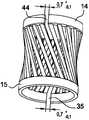
図10(D)に示す実施形態では、環は特に縦穴の位置で開いており、横桟14に形成されている第一の開口44を有する。開口44は、横桟15に形成されている開口35と対角で対向している。この対角対向は、双曲面構造の回転軸(図示されていない)に関して値を決定される。結果的に、図9に示すようなシャフト3に加わる力が如何なる方向36にあれ、環の応答は同一になる。開いた環では生じがちであるような顧慮されない方向は存在しない。
In the embodiment shown in FIG. 10 (D), the ring is open at the position of the vertical hole, and has a
環の開口は、構造6に形成されている凹部37への環5の挿入を可能にする。開口4
4及び/又は開口35が狭まって、挿入、さらには締め付けが可能になる。さらに、狭まることから、構造6においてシャフト3の端部を受け入れる凹部の形成時に、より大きい公差を許容することが可能になる。
The opening of the ring makes it possible to insert the
4 and / or
これらの実施形態は、シャフト3において、環5を収容すべき位置に回転によって得られるくぼみ38を設けることにより、特に単純なシャフト3の長手方向把持を達成することを可能にする。このくぼみ38は例えば、曲率31と曲率32との間の中間の曲率を有する。必要があれば、他方の側に位置する堅固な構造4において、同じ環39を備えたもう一つの軸受を形成してシャフト3の他端を把持することも可能であり、この場合にもシャフト3の他端に回転によって得られるくぼみをやはり設ける。この場合には、特にくぼみによって、シャフト3の制御された配置が得られ、長手方向のずれに対する耐久性は不要である。
These embodiments make it possible to achieve a particularly simple longitudinal grip of the
上述のように、本方法の実施形態は、薄いプレートにおいて平行な縦桟を挟んで介設される切断縦穴を形成する工程を含んでいてよく、これらの平行な縦桟は、両端を横桟によってまとめて把持されており、横桟及び縦桟は、横桟に垂直な軸を有する円形チャックの周りで成形され、円形に成形された横桟は、チャックの軸と同一線上に並ぶ軸の周りで互いに対して捻転される。 As described above, an embodiment of the method may include a step of forming a cut vertical hole interposed between parallel vertical bars in a thin plate, and these parallel vertical bars are arranged at both ends. The horizontal beam and the vertical beam are formed around a circular chuck having an axis perpendicular to the horizontal beam, and the horizontal beam formed in a circular shape is aligned with the axis of the chuck. Twisted around each other.
また、上述のように、本方法の実施形態は、薄いプレートにおいて平行な縦桟を挟んで介設される切断縦穴を形成する工程を含んでいてよく、これらの平行な縦桟は、両端を横桟によってまとめて把持されており、縦桟は、横桟に垂直な方向に対して傾斜しており、上述のようにして切断された薄いプレートは、横桟の方向に直交する回転軸での回転によって得られる形状を有する金型に圧入されることにより変形され、金型は、両端の間の中央部に横桟を収容する隆起部を有している。 Further, as described above, the embodiment of the present method may include a step of forming a cut vertical hole interposed between the parallel vertical bars in the thin plate, and these parallel vertical bars are connected to both ends. The vertical beam is inclined with respect to the direction perpendicular to the horizontal beam, and the thin plate cut as described above has a rotation axis orthogonal to the direction of the horizontal beam. The mold is deformed by being press-fitted into a mold having a shape obtained by the rotation, and the mold has a raised portion that accommodates the horizontal rail at the center between both ends.
当業者は、開示された実施形態及びこれらの均等構成の構造/方法及び/又は作用及び/又は結果及び/又は工程に対して本発明の範囲から逸脱することなく様々な改変を施し又は提案することができる。 Those skilled in the art will make or suggest various modifications to the disclosed embodiments and their equivalent structures / methods and / or actions and / or results and / or steps without departing from the scope of the present invention. be able to.
1 アノード
2 ロータ
3 シャフト
4 第一の固定構造
5 環
6 第二の構造
7 回転軸
8、9 頭冠
10 傾斜した縦桟
11 矩形プレート
12、25 縦穴
13、26 縦桟
14、15 横桟
16、19、27 軸
17、18 横桟の捻転方向
20 開口
21 中央縦穴
22、23 横桟15の両端
24 平行四辺形プレート
28 肉厚円筒の厚み
29 肉厚円筒の除去部分
30 シャフト挿入前の内径
31 シャフト挿入後の被覆の曲線
32 シャフト挿入前の被覆の曲線
33 シャフト挿入後の内径
34 応力の分布
35 開口
36 シャフトに加わる力の方向
37 凹部
38 くぼみ
39 環
44 開口
DESCRIPTION OF SYMBOLS 1
Claims (11)
第一の構造(6)と、
該第一の構造に形成されている凹部(37)と、
該凹部に収容されている環(5)と、
一端が前記環に挿入される回転するシャフト(3)と、
とを備えており、
前記シャフト(3)は、動作中発熱に起因して膨脹し、
前記環(5)が再度シャフトが挿入できるように再利用可能であり、
前記環は、一組の傾斜した縦桟(10)で構成されている鼓形形状(8〜10)を含んでおり、
前記一組の傾斜した縦桟(10)は、前記環の第一の頭冠(8)に連結されていると共に前記環の第二の頭冠(9)に連結されている、装置。 An apparatus for mounting a rotating member,
The first structure (6);
A recess (37) formed in the first structure;
A ring (5) housed in the recess;
A shaft (3) rotating one end is inserted into the ring,
And
The shaft (3) expands due to heat generation during operation,
The ring (5) is reusable so that the shaft can be inserted again;
The ring includes a hourglass shape (8-10) composed of a set of slanted vertical bars (10);
The set of slanted vertical bars (10) connected to the first crown (8) of the ring and to the second crown (9) of the ring.
前記双曲面形状は前記シャフトの前記環(5)への挿入以前に第1の曲率(32)を有し、The hyperboloid shape has a first curvature (32) prior to insertion of the shaft into the ring (5);
前記シャフトの前記環(5)への挿入後に第2の曲率(31)を有し、Having a second curvature (31) after insertion of the shaft into the ring (5);
前記シャフト(3)は、前記一端において、前記環(5)を収容すべき位置にくぼみ(38)を有しており、該くぼみ(38)は前記第1の曲率(32)と前記第2の曲率(31)との間の中間の曲率を有している、請求項3に記載の装置。The shaft (3) has a recess (38) at a position to accommodate the ring (5) at the one end, and the recess (38) has the first curvature (32) and the second curvature. The device according to claim 3, having an intermediate curvature between
The other end of the shaft is disposed in the other structure (4), and the other end has a drum shape (8 to 10) obtained by rotation about the shaft (7) of the shaft. 11. A device according to any of claims 1 to 10 , supported by two rings.
Applications Claiming Priority (1)
| Application Number | Priority Date | Filing Date | Title |
|---|---|---|---|
| FR0350113A FR2853990B1 (en) | 2003-04-17 | 2003-04-17 | DEVICE FOR MOUNTING A ROTATING ANODE OF AN X-RAY TUBE AND METHOD FOR MANUFACTURING THE SAME |
Publications (3)
| Publication Number | Publication Date |
|---|---|
| JP2004316919A JP2004316919A (en) | 2004-11-11 |
| JP2004316919A5 JP2004316919A5 (en) | 2009-07-02 |
| JP4474190B2 true JP4474190B2 (en) | 2010-06-02 |
Family
ID=33042059
Family Applications (1)
| Application Number | Title | Priority Date | Filing Date |
|---|---|---|---|
| JP2004120950A Expired - Fee Related JP4474190B2 (en) | 2003-04-17 | 2004-04-16 | Method and apparatus for mounting rotating member |
Country Status (3)
| Country | Link |
|---|---|
| US (2) | US7149281B2 (en) |
| JP (1) | JP4474190B2 (en) |
| FR (1) | FR2853990B1 (en) |
Families Citing this family (9)
| Publication number | Priority date | Publication date | Assignee | Title |
|---|---|---|---|---|
| GB0308957D0 (en) | 2003-04-17 | 2003-05-28 | Lillishall Plastics And Engine | Tolerance ring assembly |
| DE102005018369A1 (en) * | 2005-03-30 | 2006-10-05 | Hofmann Mess- Und Auswuchttechnik Gmbh & Co. Kg | Rotating anode X-ray tube |
| DE102006017305A1 (en) * | 2006-04-12 | 2007-10-18 | Gerd Eisenblätter Gmbh | Mounting system, mounting adapter and mounting method |
| US7850389B2 (en) * | 2006-08-15 | 2010-12-14 | Intriplex Technologies, Inc. | Tolerance ring having various end tab designs to prevent interlocking |
| US8233242B2 (en) * | 2007-04-24 | 2012-07-31 | Saint-Gobain Performance Plastics Rencol Limited | Tolerance ring with overlapping layers |
| DE202007012052U1 (en) * | 2007-08-29 | 2009-01-08 | Oerlikon Leybold Vacuum Gmbh | Turbo molecular pump |
| US8414348B2 (en) * | 2009-02-13 | 2013-04-09 | Flambeau, Inc. | Reconfigurable rotatable performance device |
| US8968049B2 (en) | 2011-03-31 | 2015-03-03 | Flambeau, Inc. | Spacer for an adjustable width rotatable performance device |
| WO2016010692A1 (en) * | 2014-07-15 | 2016-01-21 | Zachary Aaron Coon | Hyperboloid device with sliding elements |
Family Cites Families (26)
| Publication number | Priority date | Publication date | Assignee | Title |
|---|---|---|---|---|
| US246846A (en) * | 1881-09-06 | wilde | ||
| USRE24783E (en) * | 1960-02-16 | Apparatus and method for making spirally corrugated metal tubes | ||
| US1013769A (en) * | 1909-12-01 | 1912-01-02 | Broderick Haskell | Machine for making spiral latticed poles or the like. |
| US1554781A (en) * | 1923-10-10 | 1925-09-22 | Blecker Lipman | Diabolo |
| US1833145A (en) * | 1925-07-07 | 1931-11-24 | Wilhelm Harold Frederick | Connecter |
| US2569850A (en) * | 1947-03-08 | 1951-10-02 | Atf Inc | Crimping device |
| US2640168A (en) * | 1950-11-09 | 1953-05-26 | Machlett Lab Inc | Electron tube |
| US2785453A (en) * | 1952-06-11 | 1957-03-19 | Alan W Wentz | Separable fastener structure |
| US3270697A (en) * | 1962-10-02 | 1966-09-06 | B & W Inc | Method for forming a pipe centering device |
| US3271053A (en) * | 1964-07-02 | 1966-09-06 | Kurachi Hisaharu | Means for coupling a hose to a pipe |
| US3394972A (en) * | 1965-05-21 | 1968-07-30 | Kaman Corp | Journal bearing |
| FR1470088A (en) * | 1967-04-21 | 1967-02-17 | Torrington Mfg Co | Manufacturing process for bearing cages |
| US3902772A (en) * | 1973-06-14 | 1975-09-02 | Schaeffler Ohg Industriewerk | Bearing cage |
| US4130926A (en) * | 1977-02-17 | 1978-12-26 | Ceraver S.A. | Method of producing a rod anchoring structure |
| US4203312A (en) * | 1977-09-29 | 1980-05-20 | Spiral Tubing Corporation | Corrugated tubing with variable depth corrugations and method of making the same |
| NL7713634A (en) * | 1977-12-09 | 1979-06-12 | Philips Nv | ROSE TUBE WITH TWIST CODE. |
| US4286894A (en) * | 1979-03-21 | 1981-09-01 | Roller Bearing Company Of America | Tolerance rings |
| FR2506873B1 (en) * | 1981-06-01 | 1986-08-22 | Glaenzer Spicer Sa | AXIAL RETAINING TRIPOD JOINT |
| DE3151229A1 (en) * | 1981-12-23 | 1983-06-30 | Siemens AG, 1000 Berlin und 8000 München | Method and device for optimising the emission of an X-ray tube |
| US4474493A (en) * | 1982-09-09 | 1984-10-02 | Modular Systems, Inc. | Dowel fastener and joints including same |
| CS232586B1 (en) * | 1983-03-31 | 1985-02-14 | Frantisek Starek | Seating of rotating parts of a x-ray tube's anode |
| DE9017291U1 (en) * | 1990-01-11 | 1991-03-14 | Siemens Ag, 8000 Muenchen, De | |
| FR2668359B1 (en) * | 1990-10-24 | 1998-02-20 | Gen Electric Cgr | MAMMOGRAPH PROVIDED WITH A PERFECTED NEEDLE HOLDER. |
| FR2717619B1 (en) * | 1994-03-18 | 1996-04-26 | Ge Medical Syst Sa | X-ray tube with spectrum of lines of varying relative intensity. |
| JP3399513B2 (en) * | 1999-08-10 | 2003-04-21 | 日本電気株式会社 | Helical antenna and manufacturing method thereof |
| FR2846784B1 (en) * | 2002-10-30 | 2005-02-11 | Ge Med Sys Global Tech Co Llc | BEARING ASSEMBLY FOR ROTATING MOUNTING OF ROTARY ANODE OF X-RAY TRANSMITTING DEVICE AND X-RAY TRANSMITTING DEVICE EQUIPPED WITH SUCH AN ASSEMBLY |
-
2003
- 2003-04-17 FR FR0350113A patent/FR2853990B1/en not_active Expired - Fee Related
-
2004
- 2004-04-15 US US10/825,512 patent/US7149281B2/en not_active Expired - Fee Related
- 2004-04-16 JP JP2004120950A patent/JP4474190B2/en not_active Expired - Fee Related
-
2006
- 2006-10-30 US US11/589,467 patent/US20070101794A1/en not_active Abandoned
Also Published As
| Publication number | Publication date |
|---|---|
| FR2853990B1 (en) | 2006-12-29 |
| US20070101794A1 (en) | 2007-05-10 |
| US20040240615A1 (en) | 2004-12-02 |
| US7149281B2 (en) | 2006-12-12 |
| FR2853990A1 (en) | 2004-10-22 |
| JP2004316919A (en) | 2004-11-11 |
Similar Documents
| Publication | Publication Date | Title |
|---|---|---|
| US20070101794A1 (en) | Method and device for mounting a rotating member | |
| JPH0787082B2 (en) | Rotating anode target for X-ray tube | |
| BR112014018852B1 (en) | ENGINE AND VIBRATION REDUCTION METHOD FOR ONE ENGINE | |
| US20180252237A1 (en) | Impeller | |
| JP2006258286A (en) | Oscillating reduction bracket | |
| US11233445B2 (en) | Acoustic noise mitigation system for an electric machine | |
| US20070188027A1 (en) | Motor | |
| JP6895200B2 (en) | Piezoelectric motors, sliding materials for piezoelectric motors, and injection equipment | |
| US6762540B2 (en) | One-piece tab assembly for a cathode cup of an X-ray imaging machine | |
| WO2013175329A1 (en) | Balancing in an x-ray tube | |
| WO2015079883A1 (en) | X-ray diagnostic device, method for detecting sign of failure of x-ray tube, and rotating-positive-electrode x-ray tube | |
| JP2004316919A5 (en) | ||
| EP1744179B1 (en) | Device for guiding the movement of a transducer of an ultrasonic probe | |
| JPH07336940A (en) | Structure for preventing deformation of motor for generating vibration | |
| JP2018510745A (en) | Dental and / or surgical instrument with cartridge and corresponding cartridge | |
| JPH11319711A (en) | Vibration generating apparatus and installation of weight therein | |
| JP5639483B2 (en) | X-ray CT system | |
| JP5646876B2 (en) | Rotating anode X-ray tube and X-ray tube apparatus having the same | |
| JPH1080080A (en) | Brushless motor | |
| JP4805212B2 (en) | Vibration reduction member | |
| JPH0965604A (en) | Rotary electric machine | |
| JP6318245B2 (en) | Installation of rotating anode suitable for thermal expansion | |
| JPS6019619B2 (en) | Rotating anode for X-ray tube | |
| EP2789003B1 (en) | Balancing of a rotating anode | |
| US20200378468A1 (en) | Damping means of an electric motor of an airflow generating apparatus and said apparatus comprising the damping means |
Legal Events
| Date | Code | Title | Description |
|---|---|---|---|
| A521 | Request for written amendment filed |
Free format text: JAPANESE INTERMEDIATE CODE: A523 Effective date: 20070323 |
|
| A621 | Written request for application examination |
Free format text: JAPANESE INTERMEDIATE CODE: A621 Effective date: 20070323 |
|
| A521 | Request for written amendment filed |
Free format text: JAPANESE INTERMEDIATE CODE: A523 Effective date: 20090518 |
|
| A131 | Notification of reasons for refusal |
Free format text: JAPANESE INTERMEDIATE CODE: A131 Effective date: 20091027 |
|
| A521 | Request for written amendment filed |
Free format text: JAPANESE INTERMEDIATE CODE: A523 Effective date: 20100120 |
|
| RD02 | Notification of acceptance of power of attorney |
Free format text: JAPANESE INTERMEDIATE CODE: A7422 Effective date: 20100120 |
|
| RD04 | Notification of resignation of power of attorney |
Free format text: JAPANESE INTERMEDIATE CODE: A7424 Effective date: 20100120 |
|
| TRDD | Decision of grant or rejection written | ||
| A01 | Written decision to grant a patent or to grant a registration (utility model) |
Free format text: JAPANESE INTERMEDIATE CODE: A01 Effective date: 20100216 |
|
| A01 | Written decision to grant a patent or to grant a registration (utility model) |
Free format text: JAPANESE INTERMEDIATE CODE: A01 |
|
| A61 | First payment of annual fees (during grant procedure) |
Free format text: JAPANESE INTERMEDIATE CODE: A61 Effective date: 20100308 |
|
| FPAY | Renewal fee payment (event date is renewal date of database) |
Free format text: PAYMENT UNTIL: 20130312 Year of fee payment: 3 |
|
| R150 | Certificate of patent or registration of utility model |
Ref document number: 4474190 Country of ref document: JP Free format text: JAPANESE INTERMEDIATE CODE: R150 Free format text: JAPANESE INTERMEDIATE CODE: R150 |
|
| FPAY | Renewal fee payment (event date is renewal date of database) |
Free format text: PAYMENT UNTIL: 20130312 Year of fee payment: 3 |
|
| FPAY | Renewal fee payment (event date is renewal date of database) |
Free format text: PAYMENT UNTIL: 20140312 Year of fee payment: 4 |
|
| R250 | Receipt of annual fees |
Free format text: JAPANESE INTERMEDIATE CODE: R250 |
|
| R250 | Receipt of annual fees |
Free format text: JAPANESE INTERMEDIATE CODE: R250 |
|
| R250 | Receipt of annual fees |
Free format text: JAPANESE INTERMEDIATE CODE: R250 |
|
| R250 | Receipt of annual fees |
Free format text: JAPANESE INTERMEDIATE CODE: R250 |
|
| R250 | Receipt of annual fees |
Free format text: JAPANESE INTERMEDIATE CODE: R250 |
|
| R250 | Receipt of annual fees |
Free format text: JAPANESE INTERMEDIATE CODE: R250 |
|
| R250 | Receipt of annual fees |
Free format text: JAPANESE INTERMEDIATE CODE: R250 |
|
| LAPS | Cancellation because of no payment of annual fees |