JP4473322B2 - Holding control valve - Google Patents
Holding control valve Download PDFInfo
- Publication number
- JP4473322B2 JP4473322B2 JP2008094358A JP2008094358A JP4473322B2 JP 4473322 B2 JP4473322 B2 JP 4473322B2 JP 2008094358 A JP2008094358 A JP 2008094358A JP 2008094358 A JP2008094358 A JP 2008094358A JP 4473322 B2 JP4473322 B2 JP 4473322B2
- Authority
- JP
- Japan
- Prior art keywords
- pilot
- pressure
- piston
- valve
- relief
- Prior art date
- Legal status (The legal status is an assumption and is not a legal conclusion. Google has not performed a legal analysis and makes no representation as to the accuracy of the status listed.)
- Active
Links
- 239000003921 oil Substances 0.000 claims description 75
- 239000010720 hydraulic oil Substances 0.000 claims description 30
- 238000011144 upstream manufacturing Methods 0.000 description 8
- 230000002093 peripheral effect Effects 0.000 description 6
- 230000002195 synergetic effect Effects 0.000 description 6
- 238000010586 diagram Methods 0.000 description 5
- 230000003247 decreasing effect Effects 0.000 description 4
- 230000007935 neutral effect Effects 0.000 description 3
- 238000007599 discharging Methods 0.000 description 2
- 238000005259 measurement Methods 0.000 description 2
- 239000007787 solid Substances 0.000 description 2
- 230000008485 antagonism Effects 0.000 description 1
- 230000001174 ascending effect Effects 0.000 description 1
- 230000000903 blocking effect Effects 0.000 description 1
- 239000012530 fluid Substances 0.000 description 1
- 230000014759 maintenance of location Effects 0.000 description 1
- 230000004044 response Effects 0.000 description 1
Images


Classifications
-
- F—MECHANICAL ENGINEERING; LIGHTING; HEATING; WEAPONS; BLASTING
- F15—FLUID-PRESSURE ACTUATORS; HYDRAULICS OR PNEUMATICS IN GENERAL
- F15B—SYSTEMS ACTING BY MEANS OF FLUIDS IN GENERAL; FLUID-PRESSURE ACTUATORS, e.g. SERVOMOTORS; DETAILS OF FLUID-PRESSURE SYSTEMS, NOT OTHERWISE PROVIDED FOR
- F15B13/00—Details of servomotor systems ; Valves for servomotor systems
- F15B13/01—Locking-valves or other detent i.e. load-holding devices
-
- F—MECHANICAL ENGINEERING; LIGHTING; HEATING; WEAPONS; BLASTING
- F15—FLUID-PRESSURE ACTUATORS; HYDRAULICS OR PNEUMATICS IN GENERAL
- F15B—SYSTEMS ACTING BY MEANS OF FLUIDS IN GENERAL; FLUID-PRESSURE ACTUATORS, e.g. SERVOMOTORS; DETAILS OF FLUID-PRESSURE SYSTEMS, NOT OTHERWISE PROVIDED FOR
- F15B11/00—Servomotor systems without provision for follow-up action; Circuits therefor
- F15B11/02—Systems essentially incorporating special features for controlling the speed or actuating force of an output member
- F15B11/04—Systems essentially incorporating special features for controlling the speed or actuating force of an output member for controlling the speed
- F15B11/044—Systems essentially incorporating special features for controlling the speed or actuating force of an output member for controlling the speed by means in the return line, i.e. "meter out"
-
- F—MECHANICAL ENGINEERING; LIGHTING; HEATING; WEAPONS; BLASTING
- F15—FLUID-PRESSURE ACTUATORS; HYDRAULICS OR PNEUMATICS IN GENERAL
- F15B—SYSTEMS ACTING BY MEANS OF FLUIDS IN GENERAL; FLUID-PRESSURE ACTUATORS, e.g. SERVOMOTORS; DETAILS OF FLUID-PRESSURE SYSTEMS, NOT OTHERWISE PROVIDED FOR
- F15B2211/00—Circuits for servomotor systems
- F15B2211/20—Fluid pressure source, e.g. accumulator or variable axial piston pump
- F15B2211/205—Systems with pumps
- F15B2211/2053—Type of pump
- F15B2211/20538—Type of pump constant capacity
-
- F—MECHANICAL ENGINEERING; LIGHTING; HEATING; WEAPONS; BLASTING
- F15—FLUID-PRESSURE ACTUATORS; HYDRAULICS OR PNEUMATICS IN GENERAL
- F15B—SYSTEMS ACTING BY MEANS OF FLUIDS IN GENERAL; FLUID-PRESSURE ACTUATORS, e.g. SERVOMOTORS; DETAILS OF FLUID-PRESSURE SYSTEMS, NOT OTHERWISE PROVIDED FOR
- F15B2211/00—Circuits for servomotor systems
- F15B2211/30—Directional control
- F15B2211/305—Directional control characterised by the type of valves
- F15B2211/30505—Non-return valves, i.e. check valves
- F15B2211/30515—Load holding valves
-
- F—MECHANICAL ENGINEERING; LIGHTING; HEATING; WEAPONS; BLASTING
- F15—FLUID-PRESSURE ACTUATORS; HYDRAULICS OR PNEUMATICS IN GENERAL
- F15B—SYSTEMS ACTING BY MEANS OF FLUIDS IN GENERAL; FLUID-PRESSURE ACTUATORS, e.g. SERVOMOTORS; DETAILS OF FLUID-PRESSURE SYSTEMS, NOT OTHERWISE PROVIDED FOR
- F15B2211/00—Circuits for servomotor systems
- F15B2211/30—Directional control
- F15B2211/305—Directional control characterised by the type of valves
- F15B2211/30525—Directional control valves, e.g. 4/3-directional control valve
-
- F—MECHANICAL ENGINEERING; LIGHTING; HEATING; WEAPONS; BLASTING
- F15—FLUID-PRESSURE ACTUATORS; HYDRAULICS OR PNEUMATICS IN GENERAL
- F15B—SYSTEMS ACTING BY MEANS OF FLUIDS IN GENERAL; FLUID-PRESSURE ACTUATORS, e.g. SERVOMOTORS; DETAILS OF FLUID-PRESSURE SYSTEMS, NOT OTHERWISE PROVIDED FOR
- F15B2211/00—Circuits for servomotor systems
- F15B2211/30—Directional control
- F15B2211/31—Directional control characterised by the positions of the valve element
- F15B2211/3105—Neutral or centre positions
- F15B2211/3111—Neutral or centre positions the pump port being closed in the centre position, e.g. so-called closed centre
-
- F—MECHANICAL ENGINEERING; LIGHTING; HEATING; WEAPONS; BLASTING
- F15—FLUID-PRESSURE ACTUATORS; HYDRAULICS OR PNEUMATICS IN GENERAL
- F15B—SYSTEMS ACTING BY MEANS OF FLUIDS IN GENERAL; FLUID-PRESSURE ACTUATORS, e.g. SERVOMOTORS; DETAILS OF FLUID-PRESSURE SYSTEMS, NOT OTHERWISE PROVIDED FOR
- F15B2211/00—Circuits for servomotor systems
- F15B2211/30—Directional control
- F15B2211/32—Directional control characterised by the type of actuation
- F15B2211/329—Directional control characterised by the type of actuation actuated by fluid pressure
-
- F—MECHANICAL ENGINEERING; LIGHTING; HEATING; WEAPONS; BLASTING
- F15—FLUID-PRESSURE ACTUATORS; HYDRAULICS OR PNEUMATICS IN GENERAL
- F15B—SYSTEMS ACTING BY MEANS OF FLUIDS IN GENERAL; FLUID-PRESSURE ACTUATORS, e.g. SERVOMOTORS; DETAILS OF FLUID-PRESSURE SYSTEMS, NOT OTHERWISE PROVIDED FOR
- F15B2211/00—Circuits for servomotor systems
- F15B2211/60—Circuit components or control therefor
- F15B2211/635—Circuits providing pilot pressure to pilot pressure-controlled fluid circuit elements
-
- F—MECHANICAL ENGINEERING; LIGHTING; HEATING; WEAPONS; BLASTING
- F15—FLUID-PRESSURE ACTUATORS; HYDRAULICS OR PNEUMATICS IN GENERAL
- F15B—SYSTEMS ACTING BY MEANS OF FLUIDS IN GENERAL; FLUID-PRESSURE ACTUATORS, e.g. SERVOMOTORS; DETAILS OF FLUID-PRESSURE SYSTEMS, NOT OTHERWISE PROVIDED FOR
- F15B2211/00—Circuits for servomotor systems
- F15B2211/70—Output members, e.g. hydraulic motors or cylinders or control therefor
- F15B2211/705—Output members, e.g. hydraulic motors or cylinders or control therefor characterised by the type of output members or actuators
- F15B2211/7051—Linear output members
- F15B2211/7053—Double-acting output members
-
- Y—GENERAL TAGGING OF NEW TECHNOLOGICAL DEVELOPMENTS; GENERAL TAGGING OF CROSS-SECTIONAL TECHNOLOGIES SPANNING OVER SEVERAL SECTIONS OF THE IPC; TECHNICAL SUBJECTS COVERED BY FORMER USPC CROSS-REFERENCE ART COLLECTIONS [XRACs] AND DIGESTS
- Y10—TECHNICAL SUBJECTS COVERED BY FORMER USPC
- Y10T—TECHNICAL SUBJECTS COVERED BY FORMER US CLASSIFICATION
- Y10T137/00—Fluid handling
- Y10T137/7722—Line condition change responsive valves
- Y10T137/7758—Pilot or servo controlled
- Y10T137/7762—Fluid pressure type
- Y10T137/7764—Choked or throttled pressure type
- Y10T137/7766—Choked passage through main valve head
Landscapes
- Engineering & Computer Science (AREA)
- Physics & Mathematics (AREA)
- Fluid Mechanics (AREA)
- Mechanical Engineering (AREA)
- General Engineering & Computer Science (AREA)
- Fluid-Pressure Circuits (AREA)
- Fluid-Driven Valves (AREA)
- Gear-Shifting Mechanisms (AREA)
Description
本発明は、たとえば、油圧ショベル等の油圧作業機器における被作動体(シリンダ装置)を作動させるための油圧制御回路に用いられるホールディングコントロール弁に関する。 The present invention relates to a holding control valve used in a hydraulic control circuit for operating an actuated body (cylinder device) in a hydraulic working device such as a hydraulic excavator.
典型的な先行技術は、たとえば特許文献1に示されている。この特許文献1には、前記ホールディングコントロール弁を備えた油圧ショベル等の油圧作業機器を制御するための油圧制御回路が開示されている。この油圧制御回路は、ポンプと、ポンプに連通したコントロールバルブと、このコントロールバルブに負荷保持管路を介して接続されるパイロットチェック弁と、圧力室がパイロットチェック弁に接続されるシリンダ装置とを備える。
A typical prior art is disclosed in
上記パイロットチェック弁には、シリンダ装置の上記圧力室に連通する背圧室が設けられる。また、上記コントロールバルブは、中立位置にあるとき、シリンダ装置をポンプから遮断し、上昇位置に切換わったとき、シリンダ装置の圧力室にポンプの吐出油を導いて負荷を上昇させ、また、下降位置に切換わったとき、シリンダ装置の圧力室の作動油を排出して負荷を下降させる構成とされている。さらに、上記コントロールバルブを上昇位置あるいは下降位置に切換えるためのパイロット圧を制御するパイロット圧制御手段(操作レバー)を設け、パイロットチェック弁の背圧室の圧力がシリンダ装置の圧力室の負荷圧となっているとき、このパイロットチェック弁によってシリンダ装置の圧力室側からの作動油の流れを阻止し、パイロットチェック弁の背圧室の作動油を排出したとき、このパイロットチェック弁が開いてシリンダ装置の圧力室側からの作動油の流れを許容し得るようになされている。 The pilot check valve is provided with a back pressure chamber communicating with the pressure chamber of the cylinder device. When the control valve is in the neutral position, the cylinder device is shut off from the pump, and when the control valve is switched to the raised position, the pump discharge oil is guided to the pressure chamber of the cylinder device to increase the load and to lower. When the position is switched, the hydraulic oil in the pressure chamber of the cylinder device is discharged and the load is lowered. Further, a pilot pressure control means (control lever) for controlling the pilot pressure for switching the control valve to the raised position or the lowered position is provided, and the pressure of the back pressure chamber of the pilot check valve is equal to the load pressure of the pressure chamber of the cylinder device. This pilot check valve prevents the flow of hydraulic oil from the pressure chamber side of the cylinder device, and when the hydraulic oil in the back pressure chamber of the pilot check valve is discharged, the pilot check valve opens and the cylinder device The hydraulic oil can be allowed to flow from the pressure chamber side.
そして、シリンダ装置の圧力室とパイロットチェック弁との間に接続した連結路と、ノーマル状態で連結路を遮断し、切換わった状態で連結路を開くとともに絞りを介してシリンダ装置の圧力室を負荷保持管路とを連通する第1切換手段と、ノーマル状態で、パイロットチェック弁の背圧室の圧力をシリンダ装置の圧力室の負荷圧に維持し、切換わった状態で背圧室の作動油を排出する第2切換手段とを備え、これら第1、2切換手段を、コントロールバルブを下降位置に切換えるためのパイロット圧によって切換える構成とし、しかも、そのパイロット圧が所定圧以下であれば、第1切換手段だけが切換わり、このパイロット圧が所定圧を超えれば、第1切換手段とともに第2切換手段も切換わるよう構成されている。 Then, the connection path connected between the pressure chamber of the cylinder device and the pilot check valve, and the connection path is shut off in the normal state, the connection path is opened in the switched state, and the pressure chamber of the cylinder device is opened via the throttle. The first switching means that communicates with the load holding conduit and the pressure of the back pressure chamber of the pilot check valve are maintained at the load pressure of the pressure chamber of the cylinder device in the normal state, and the back pressure chamber operates in the switched state. A second switching means for discharging oil, and the first and second switching means are configured to be switched by a pilot pressure for switching the control valve to the lowered position, and if the pilot pressure is not more than a predetermined pressure, Only the first switching means is switched, and when the pilot pressure exceeds a predetermined pressure, the second switching means is switched together with the first switching means.
前記第1,2切換手段は、コントロールバルブからのパイロット圧の導入によって、スプールをスプリング力(圧)に抗して動作させるようにした切換弁によって構成されている。また、シリンダ装置の圧力室とパイロットチェック弁との連結路から分岐する分岐路にリリーフ弁が配設され、このリリーフ弁は、そのリリーフ油の出口側が絞り部材を介してドレーンタンクに連結されるとともに、絞り部材の上流側において分岐して前記切換弁のパイロット圧の導入部側スプール孔に連通されている。 The first and second switching means are constituted by a switching valve that operates the spool against the spring force (pressure) by introducing pilot pressure from the control valve. In addition, a relief valve is disposed in a branch path that branches from a connection path between the pressure chamber of the cylinder device and the pilot check valve, and the relief valve outlet side is connected to the drain tank via a throttle member. At the same time, it branches on the upstream side of the throttle member and communicates with the pilot pressure introducing portion side spool hole of the switching valve.
このような構成において、シリンダ装置の負荷を一定状態に保持しているとき、すなわちコントロールバルブをノーマル状態に維持しているときに、シリンダ装置に外力が加わると、シリンダ装置の圧力室の負荷圧が上昇し、リリーフ弁が作動してリリーフ油がリリーフ弁より流出する。この流出側(出口側)は絞り部材の存在によって、絞り部材の上流側に圧力が発生する。絞り部材の上流側で発生した圧力は、前記スプール孔に導かれる。リリーフ弁からこのスプール孔への導入口は、スプールと、スプールに近接配置されたピストンとの隣接部分に位置しており、スプール孔に導かれた前記リリーフ弁からのリリーフ油による圧力は、この隣接部分においてスプールとピストンとに作用することになる。したがって、スプールとピストンとは互いに離れる方向に移動し、切換弁の第2切換手段が切換って、シリンダ装置の圧力室からの油をコントロールバルブに流すように構成されている。 In such a configuration, when an external force is applied to the cylinder device when the load of the cylinder device is kept constant, that is, when the control valve is maintained in a normal state, the load pressure of the pressure chamber of the cylinder device is increased. Rises, the relief valve is activated, and the relief oil flows out of the relief valve. On the outflow side (outlet side), the presence of the throttle member generates pressure on the upstream side of the throttle member. The pressure generated on the upstream side of the throttle member is guided to the spool hole. The inlet from the relief valve to the spool hole is located in an adjacent portion between the spool and the piston disposed in the vicinity of the spool, and the pressure by the relief oil from the relief valve guided to the spool hole is It acts on the spool and the piston in the adjacent portion. Therefore, the spool and the piston move in a direction away from each other, and the second switching means of the switching valve is switched to flow oil from the pressure chamber of the cylinder device to the control valve.
図7は、上記油圧制御回路に組み込まれた切換弁におけるパイロット圧およびリリーフ油の導入部を含む部分の構造を概念的に示す図である。図7において、切換弁Aのスプール孔Bにはその軸線に沿ってスライド可能にスプールCが嵌挿保持されている。スプール孔Bの一端側はプラグDが螺合されて封止されている。このプラグDとスプールCとの間には、スプールCよりも大径のピストンEが介在され、ピストンEとプラグDとの間がコントロールバルブ(図示せず)から導入されるパイロット圧Pの受圧部とされている。また、ピストンEとスプールCとの間の空域に、シリンダ装置Fに連結されたリリーフ弁Gからのリリーフ油G1が導入され、この空域部がリリーフ作動時の受圧部とされている。ピストンEには、パイロット圧Pの受圧部からリリーフ作動時の受圧部に至る連通路E1が形成され、該連通路E1は途中にオリフィスE2を備えている。 FIG. 7 is a diagram conceptually showing the structure of a portion including the pilot pressure and relief oil introducing portion in the switching valve incorporated in the hydraulic control circuit. In FIG. 7, a spool C is fitted and held in the spool hole B of the switching valve A so as to be slidable along its axis. One end of the spool hole B is sealed with a plug D screwed thereto. Between the plug D and the spool C, a piston E having a diameter larger than that of the spool C is interposed, and the pressure between the piston E and the plug D is received by a pilot pressure P introduced from a control valve (not shown). It is considered to be a part. Relief oil G1 from the relief valve G connected to the cylinder device F is introduced into the air space between the piston E and the spool C, and this air space portion is used as a pressure receiving portion during the relief operation. The piston E is formed with a communication path E1 from the pressure receiving part of the pilot pressure P to the pressure receiving part during the relief operation, and the communication path E1 is provided with an orifice E2 in the middle.
なお、図7における前記導入部を含む部分以外の切換弁の構造および油圧制御回路の構成は特許文献1の図2および図1に示される構成と略同様であるので、その説明は省略する。
Since the structure of the switching valve and the structure of the hydraulic control circuit other than the part including the introduction part in FIG. 7 are substantially the same as the structure shown in FIGS. 2 and 1 of
上記のような構造の切換弁において、導入されたパイロット圧PによってピストンEが押し上げられ、スプールCは大径のピストンEによって押圧されて第1切換手段に切換る。さらにパイロット圧力Pが上昇して所定圧力を超えれば、第1切換手段とともに第2切換手段も切換わる。また、リリーフ油G1が導入されても、リリーフ油G1の油圧が付加されてスプールCは第2切換手段に切換わる。そして、シリンダ装置Fが高負荷(高圧)状態となると、リリーフ弁Gが前漏れ(設定圧力以下の圧力で通過流量が増加する現象)を生じ、前記絞り部材による圧力損失が発生する。このような圧力損失の発生によって、パイロット圧と対抗する油圧力が発生することで、パイロット圧に追従せず前記第1および第2切換手段の開口開始ポイントがずれてしまう問題点があった。 In the switching valve having the above-described structure, the piston E is pushed up by the introduced pilot pressure P, and the spool C is pressed by the large-diameter piston E to switch to the first switching means. When the pilot pressure P further increases and exceeds a predetermined pressure, the second switching means is switched together with the first switching means. Further, even when the relief oil G1 is introduced, the oil pressure of the relief oil G1 is applied and the spool C is switched to the second switching means. When the cylinder device F enters a high load (high pressure) state, the relief valve G causes a pre-leak (a phenomenon in which the passage flow rate increases at a pressure equal to or lower than the set pressure), and pressure loss due to the throttle member occurs. Due to the occurrence of such a pressure loss, an oil pressure that opposes the pilot pressure is generated, so that there is a problem that the opening start points of the first and second switching means are shifted without following the pilot pressure.
図8は、シリンダ装置のボトム側に30MPaが発生している状態を模擬した状態で、パイロット圧Pを負荷した場合のパイロット圧Pと、シリンダポート圧と、切換弁およびパイロットチェック弁を通過する流量の関係について実測した結果をグラフにしたものである。図8において実線は切換弁およびパイロットチェック弁を通過する流量の変化を、破線はシリンダポート圧の変化を示している。図8から理解されるとおり、流量増加側は、開口ポイントの設定値1MPaを過ぎても流量変化が少なく、1.6MPa付近から増加を始め、流量減少側は、1MPaを超えて低下しても0L/minにならない。このことはパイロット圧Pに対する追従性が悪く、上記開口開始ポイントがずれることを意味している。 FIG. 8 shows a state in which 30 MPa is generated on the bottom side of the cylinder device, and passes through the pilot pressure P, the cylinder port pressure, the switching valve, and the pilot check valve when the pilot pressure P is applied. The graph shows the results of actual measurement of the flow rate relationship. In FIG. 8, a solid line indicates a change in the flow rate passing through the switching valve and the pilot check valve, and a broken line indicates a change in the cylinder port pressure. As understood from FIG. 8, the flow rate increasing side has a small flow rate change even when the opening point set value of 1 MPa is exceeded, starts increasing from around 1.6 MPa, and the flow rate decreasing side is decreased beyond 1 MPa. Does not reach 0 L / min. This means that the followability to the pilot pressure P is poor and the opening start point is shifted.
本発明の目的は、開口開始ポイントがずれることのない、パイロットチェック弁、切換弁およびリリーフ弁を備える、ホールディングコントロール弁を提供することである。 An object of the present invention is to provide a holding control valve including a pilot check valve, a switching valve, and a relief valve in which the opening start point does not deviate.
本発明に係るホールディングコントロール弁は、被作動体を作動させるための油圧制御回路に用いられるホールディングコントロール弁であって、
前記被作動体の圧力室に連結されるパイロットチェック弁と、
前記パイロットチェック弁の背圧室の圧力が前記被作動体の圧力室の負荷圧となっているとき、パイロットチェック弁によって被作動体の圧力室側からの作動油の流れを阻止し、パイロットチェック弁の背圧室の作動油を排出したとき、このパイロットチェック弁が開いて被作動体の圧力室側からの作動油の流れを許容するために、パイロット圧の導入によってスプールをスプリング圧に抗して動作させるよう構成された切換弁と、
前記被作動体の圧力室とパイロットチェック弁との連結路から分岐する分岐路に配設され、リリーフ油の出口側が前記切換弁のパイロット圧の導入部側に連結されるリリーフ弁とを含み、
前記スプールは、パイロット圧の導入に伴い動作するスプール径よりも大径のピストンによってストロークするように構成され、
前記ピストンは、パイロット圧を受圧するパイロットピストンと、リリーフ弁が作動したときに排出されるリリーフ油の圧力を受圧するようスプールに近接して配置されたリリーフ作動ピストンとに分割され、前記リリーフ油はパイロットピストンとリリーフ作動ピストンとの間に導入されることを特徴とするホールディングコントロール弁である。
A holding control valve according to the present invention is a holding control valve used in a hydraulic control circuit for operating an actuated body,
A pilot check valve coupled to the pressure chamber of the actuated body;
When the pressure of the back pressure chamber of the pilot check valve is the load pressure of the pressure chamber of the actuated body, the pilot check valve prevents the flow of hydraulic oil from the pressure chamber side of the actuated body, and the pilot check When the hydraulic oil in the back pressure chamber of the valve is discharged, the pilot check valve opens to allow the hydraulic oil to flow from the pressure chamber side of the operated body. A switching valve configured to operate
A relief valve disposed on a branch path branched from a connection path between the pressure chamber of the actuated body and a pilot check valve, and having a relief oil outlet side connected to a pilot pressure introduction side of the switching valve;
The spool is configured to be stroked by a piston having a diameter larger than a spool diameter that operates in accordance with introduction of pilot pressure,
The piston is divided into a pilot piston that receives a pilot pressure, and a relief operating piston that is disposed in the vicinity of the spool so as to receive the pressure of the relief oil that is discharged when the relief valve is operated. Is a holding control valve that is introduced between the pilot piston and the relief operating piston.
また本発明は、前記リリーフ作動ピストンは、前記スプールと同径とされ、該スプールよりも大径のパイロットピストンに形成された筒部に収容されていることを特徴とする。 Further, the present invention is characterized in that the relief operating piston has the same diameter as the spool and is accommodated in a cylindrical portion formed in a pilot piston having a larger diameter than the spool.
また本発明は、前記パイロットピストンの筒部を構成する筒壁に横孔が設けられ、前記リリーフ油はこの横孔を介してパイロットピストンとリリーフ作動ピストンとの間に導入されることを特徴とする。 Further, the present invention is characterized in that a horizontal hole is provided in a cylindrical wall constituting the cylindrical portion of the pilot piston, and the relief oil is introduced between the pilot piston and the relief operating piston through the horizontal hole. To do.
また本発明は、前記パイロットピストンと、リリーフ作動ピストンとは同径とされ、両者が連なるように配置されていることを特徴とする。 In the invention, it is preferable that the pilot piston and the relief operation piston have the same diameter and are arranged so as to be continuous with each other.
また本発明は、パイロットピストンのパイロット圧を受圧する面から、リリーフ作動ピストンのスプールに対面する側の面にかけて、オリフィスを備えた一連の連通路が形成されていることを特徴とする。 Further, the present invention is characterized in that a series of communication passages having an orifice are formed from a surface receiving the pilot pressure of the pilot piston to a surface facing the spool of the relief operation piston.
本発明のホールディングコントロール弁によれば、被作動体の圧力室に連結されるパイロットチェック弁において、その背圧室の圧力が前記被作動体の圧力室の負荷圧となっているとき、被作動体の圧力室側からの作動油の流れが阻止される。また、パイロットチェック弁の背圧室の作動油を排出したとき、パイロットチェック弁が開いて被作動体の圧力室側からの流れが許容される。このようなパイロットチェック弁の動作は、コントロールバルブからのパイロット圧によって切換制御される切換弁によってなされる。この切換制御は、パイロット圧の圧力を受けたピストンの押圧作用によってスプールをストローク動作させることによってなされ、しかも、ピストン径がスプール径より大とされているから、この押圧作用がスプールに効果的に付与される。 According to the holding control valve of the present invention, in the pilot check valve connected to the pressure chamber of the operated body, when the pressure of the back pressure chamber is the load pressure of the pressure chamber of the operated body, The flow of hydraulic oil from the pressure chamber side of the body is blocked. Further, when the hydraulic oil in the back pressure chamber of the pilot check valve is discharged, the pilot check valve is opened and the flow from the pressure chamber side of the operated body is allowed. Such an operation of the pilot check valve is performed by a switching valve that is switch-controlled by the pilot pressure from the control valve. This switching control is performed by causing the spool to stroke by the pressing action of the piston that has received the pressure of the pilot pressure, and since the piston diameter is larger than the spool diameter, this pressing action is effective for the spool. Is granted.
そして、前記被作動体の圧力室とパイロットチェック弁との連結路から分岐する分岐路に配設されたリリーフ弁が作動したときに排出されるリリーフ油が、切換弁におけるパイロット圧の導入部側に導入されてから、スプールはパイロット圧を受けた動作と、リリーフ油の油圧が付加された動作を行う。この場合、前記ピストンは、パイロット圧を受圧するパイロットピストンと、リリーフ弁が作動したときに排出されるリリーフ油の圧力を受圧するようスプールに近接配置されたリリーフ作動ピストンとに分割され、前記リリーフ油は、パイロットピストンとリリーフ作動ピストンとの間に導入されるように構成される。したがって、リリーフ作動前の前漏れで発生する油圧力は、パイロット圧によってパイロットピストンに作用する油圧力と、スプールを介して対抗するスプリング力とが釣り合っている状態の内力となるので、パイロットチェック弁での開口開始ポイントはずれなくなり、パイロットチェック弁の開動作が円滑になされる。 Then, the relief oil discharged when the relief valve disposed in the branch path branched from the connection path between the pressure chamber of the actuated body and the pilot check valve is operated, the pilot pressure introduction side of the switching valve After being introduced into the spool, the spool performs an operation receiving a pilot pressure and an operation to which a hydraulic pressure of relief oil is added. In this case, the piston is divided into a pilot piston that receives the pilot pressure, and a relief operating piston that is disposed close to the spool so as to receive the pressure of the relief oil that is discharged when the relief valve is operated. The oil is configured to be introduced between the pilot piston and the relief actuating piston. Therefore, the oil pressure generated by the pre-leakage before the relief operation is an internal force in a state where the oil pressure acting on the pilot piston by the pilot pressure is balanced with the spring force opposed through the spool. The opening start point at is no longer deviated, and the pilot check valve is opened smoothly.
前記リリーフ作動ピストンを前記スプールと同径とし、該スプールよりも大径のパイロットピストンに形成された筒部に収容されているものとすれば、ピストンを軸線方向にコンパクトな構造とすることができる。この場合、前記パイロットピストンの筒部を構成する筒壁に横孔を設け、前記リリーフ油をこの横孔からパイロットピストンとリリーフ作動ピストンとの間に導入するように構成すれば、リリーフ油の導入も無理なくなされる。 If the relief operating piston has the same diameter as the spool and is accommodated in a cylindrical portion formed in a pilot piston having a larger diameter than the spool, the piston can have a compact structure in the axial direction. . In this case, if a lateral hole is provided in the cylindrical wall constituting the cylindrical portion of the pilot piston and the relief oil is introduced between the pilot piston and the relief operating piston through the lateral hole, the introduction of the relief oil is achieved. Will be made without difficulty.
また、パイロットピストンと、リリーフ作動ピストンとを同径とし、両者を連なるような配置構造とした場合、両ピストンの構造がシンプルであり、加工コストを低減することができる。 In addition, when the pilot piston and the relief operating piston have the same diameter and are arranged in a continuous manner, the structure of both pistons is simple, and the processing cost can be reduced.
さらに、パイロットピストンのパイロット圧を受圧する受圧面から、リリーフ作動ピストンのスプールに対向する側の受圧面にわたって、オリフィスを備えた一連の連通路が形成されることによって、スプールに対する、パイロット圧を受けたパイロットピストンの押圧作用と、リリーフ油の油圧を受けたリリーフ作動ピストンの押圧作用とがバランスするとともに、これらの押圧作用に対する応答性が良くなり、スプールのストローク動作制御がより的確になされる。 Furthermore, a series of communication passages with orifices are formed from the pressure receiving surface for receiving the pilot pressure of the pilot piston to the pressure receiving surface on the side facing the spool of the relief operating piston, thereby receiving the pilot pressure on the spool. Further, the pressing action of the pilot piston and the pressing action of the relief actuating piston receiving the oil pressure of the relief oil are balanced, and the response to these pressing actions is improved, so that the stroke operation control of the spool is more accurately performed.
図1は本発明の実施の一形態のホールディングコントロール弁3の一部の断面図であり、図2は図1に示すホールディングコントロール弁3の全体の構成を示す断面図であり、図3はホールディングコントロール弁3に備えられるリリーフ弁8の拡大断面図であり、図4はホールディングコントロール弁3を備える駆動制御装置の油圧回路図である。
FIG. 1 is a sectional view of a part of a holding
本発明のホールディングコントロール弁の一実施形態を図1〜図4を参照して説明する。図4は本ホールディングコントロール弁を含み、被作動体を駆動させるために構成された駆動制御装置の油圧回路図を示す。まず、この駆動制御装置について説明する。この駆動制御装置は、油圧ショベル等の油圧作業機器を制御するために構成されたものである。被作動体としてのシリンダ装置1に対し、コントロールバルブ2およびホールディングコントロール弁3を介して油圧ポンプ4が接続されている。油圧ポンプ4は、油タンク4aに貯留された作動油を、シリンダ装置1のボトム側圧力室1aおよびロッド側圧力室1bのいずれかに吐出供給する。
An embodiment of the holding control valve of the present invention will be described with reference to FIGS. FIG. 4 shows a hydraulic circuit diagram of a drive control apparatus that includes the holding control valve and is configured to drive an actuated body. First, the drive control device will be described. This drive control device is configured to control a hydraulic working device such as a hydraulic excavator. A
コントロールバルブ2は、パイロット室2a,2bに導入されるパイロット油の油圧(以下、パイロット圧と言う)によって切換るよう構成されている。操作レバー(パイロットバルブ)5は、油圧ショベル等の場合、操作者によって操作されるものであり、この操作レバー5の操作によって、パイロット室2a,2bに導入されるパイロット圧5a,5bの制御がなされる。たとえば、コントロールバルブ2は、パイロット室2aにパイロット圧5aを導入すると、パイロット圧5aの大きさに比例してシリンダ装置1を上昇させるための上昇位置2Aに切換わる。逆に、パイロット室2bにパイロット圧5bを導入すると、パイロット圧5bの大きさに比例してシリンダ装置1を下降させるための下降位置2Bに切換わる。
The
上記コントロールバルブ2と、シリンダ装置1のボトム側圧力室1aとの間には、ホールディングコントロール弁3が設けられている。このホールディングコントロール弁3は、パイロットチェック弁6と、切換弁7と、リリーフ弁8とを含む。パイロットチェック弁6は、弁部材6aを備え、該弁部材6aの先端が第1受圧面6b、側面が第2受圧面6cとされている。この弁部材6aの背面には背圧室6dが設けられるとともに、該背圧室6d内にスプリング6eが収納されており、該スプリング6eのばね力によって弁部材6aが弁座6gに着座される。背圧室6dと第2受圧面6c側の受圧室6caとは絞り通路6fを介して連通している。
A holding
ホールディングコントロール弁3における第1受圧面6b側の受圧室6baとコントロールバルブ2とは、負荷保持管路9によって接続されている。負荷保持管路9は分岐負荷保持管路9aを介して切換弁7にも通じている。
The pressure receiving chamber 6ba on the first
また、シリンダ装置1のボトム側圧力室1aとホールディングコントロール弁3における第2受圧面6c側の受圧室6caとは、連結路10によって接続され、この連結路10は、第2受圧面6c側の受圧室6caと切換弁7とを接続する延長路10aに連通し、該延長路10aを介して切換弁7に通じている。さらに、背圧室6dと切換弁7とはパイロット通路12によって接続されている。
Further, the bottom side pressure chamber 1a of the
分岐路11の途中にリリーフ弁8が配設され、該リリーフ弁8のリリーフ油の出口側分岐路11aが切換弁7におけるパイロット圧の導入部(パイロット室)7a側に連結されている。切換弁7は、遮断位置7A、第1連通位置7B、第2連通位置7Cの3つの切換位置を備えている。遮断位置7Aでは、上記連結路10の延長路10aおよびパイロット通路12の両方が閉じられる。第1連通位置7Bでは、パイロット通路12は閉じられたままであるが、延長路10aと上記負荷保持管路9の分岐負荷保持管路9aとが可変絞り部7bを介して連通する。また、第2連通位置7Cでは、パイロット通路12および延長路10aの両方が分岐負荷保持管路9aに連通する。
切換弁7のパイロット室7aには、操作レバー5の操作によって発生するパイロット圧5bが導入可能とされている。切換弁7は、ノーマル状態では遮断位置7Aにあり、パイロット室7aに所定圧以下のパイロット圧5bが導入されると、第1連通位置7Bに切換わる。さらに、パイロット室7aに所定圧を超えるパイロット圧5bが導入され、あるいはこのパイロット圧5bに加えて、後記するリリーフ弁8からのリリーフ油による圧力が加わって所定圧を超えると第2連通位置7Cに切換わる。図示では、パイロット室7aへのパイロット圧5bの導入は、2箇所よりなされるよう構成されている。前記リリーフ弁8のリリーフ油出口側分岐路11aは、さらに2経路11aa,11abに分岐され、一方の分岐経路11aaは切換弁7のパイロット室7aに導入され、他方の分岐経路11abはオリフィス流路72bを介してドレーンタンク11cに通じている。また、前記パイロット室7aとオリフィス流路72bの上流側分岐経路11abとが連結経路7cによって連結され、パイロット室7aもオリフィス流路72bを介してドレーンタンク11cに通じるよう構成されている。
A
図4に示すような油圧制御回路において、コントロールバルブ2が中立位置にあるときは、シリンダ装置1のボトム側圧力室1aおよびロッド側圧力室1bのいずれにも、油タンク4aの作動油がポンプ4から吐出供給がされない。また、切換弁7のパイロット室7aにパイロット圧5bは導入されず、切換弁7は遮断位置7Aにあるので、パイロットチェック弁6の背圧室6dの圧力は、シリンダ装置1のボトム側圧力室1aの負荷圧と拮抗し、この状態に維持される。したがって、背圧室6dの負荷圧と、背圧室6d内のスプリング6eの弾性力との相乗圧によってパイロットチェック弁6の弁部材6aが弁座6gに着座し、シリンダ装置1のボトム側圧力室1aからの作動油の流出を阻止し、シリンダ装置1に加重される負荷、すなわちシリンダ装置1のロッド1cにかかる負荷を確実に保持する。
In the hydraulic control circuit as shown in FIG. 4, when the
シリンダ装置1に加重されている負荷を上昇させようとする場合、操作レバー5を操作して、コントロールバルブ2のパイロット室2aにパイロット圧5aを導入する。このパイロット圧5aの導入によって、コントロールバルブ2は、上昇位置2Aに切換わる。コントロールバルブ2が上昇位置2Aに切換わると、ポンプ4によって油タンク4a内の作動油が負荷保持管路9を経て、パイロットチェック弁6の受圧室6baに吐出供給され、この作動油の吐出圧がパイロットチェック弁6における弁部材6aの第1受圧面6bに作用する。このとき、切換弁7はなお遮断位置7Aにあるので、パイロットチェック弁6の背圧室6d内の前記相乗圧は、シリンダ装置1のボトム側圧力室1aの負荷圧に拮抗し、パイロットチェック弁6の弁部材6aが弁座6gに着座した状態にある。しかし、第1受圧面6bに作用するポンプ4による吐出油の圧力が、背圧室6d内の前記相乗圧より大きくなると、弁部材6aが弁座6gから離れ、作動油がパイロットチェック弁6および連結路10を経てシリンダ装置1のボトム側圧力室1aに供給され、シリンダ装置1が前記負荷に抗して上昇し、これに伴いロッド側圧力室1b内の作動油が油タンク4aに排出される。
In order to increase the load applied to the
シリンダ装置1に加重されている負荷を下降させようとする場合、操作レバー5を操作して、コントロールバルブ2のパイロット室2bにパイロット圧5bを導入する。このパイロット圧5bの導入によって、コントロールバルブ2は、下降位置2Bに切換わる。コントロールバルブ2が下降位置2Bに切換わると、ポンプ4によってシリンダ装置1のロッド側圧力室1bに作動油が吐出供給される。ロッド側圧力室1bに作動油が供給されることによって、ボトム側圧力室1aの負荷圧が高められる。このとき、パイロット圧5bは、切換弁7のパイロット室7aにも導入されるので、切換弁7が第1連通位置7Bないしは第2連通位置7Cに切換わる。すなわち、パイロット室7aに導入されるパイロット圧5bが所定圧に満たない状態では、切換弁7は第1連通位置7Bに切換わる。この第1連通位置7Bでは、パイロット通路12は閉じられたままであるので、パイロットチェック弁6の背圧室6dの前記相乗圧は、シリンダ装置1のボトム側圧力室1aの負荷圧と拮抗した状態に維持される。したがって、パイロットチェック弁6の弁部材6aは、弁座6gに着座した状態を保ち、シリンダ装置1のボトム側圧力室1aからの作動油の流出が阻止される。
When the load applied to the
しかし、切換弁7が第1連通位置7Bにあるときは、パイロットチェック弁6における第2受圧面6c側の受圧室6caと切換弁7とを接続する延長路10aが、可変絞り部7bを介して分岐負荷保持管路9aに連通する。これによって、シリンダ装置1のボトム側圧力室1a内から、パイロットチェック弁6、分岐負荷保持管路9aおよび負荷保持管路9を介してコントロールバルブ2、さらには油タンク4aへ通じる経路が確立される。したがって、可変絞り部7bの開度およびコントロールバルブ2の開度を適宜調整することによって、弁部材6aが弁座6gに着座した状態を保ったまま、シリンダ装置1のボトム側圧力室1a内の負荷圧が高められた作動油が分岐負荷保持管路9aおよび負荷保持管路9を介し油タンク4aに排出され、シリンダ装置1の下降制御がなされる。この場合の下降は、可変絞り部7bによって作動油の排出が制御された状態でなされるから、ゆっくりとした下降が可能とされる。
However, the switching valve 7 when in the
コントロールバルブ2の開度を大きくすることによって、切換弁7のパイロット室7aに導入されるパイロット圧5bが所定圧を超えると(後記するリリーフ油の圧力が付加される場合もあり)、切換弁7は第2連通位置7Cに切換わる。この第2連通位置7Cでは、パイロット通路12および連結路10の延長路10aの両方が分岐負荷保持管路9aおよび負荷保持管路9に連通することになるから、パイロットチェック弁6における絞り通路6fの前後で差圧が生じ、背圧室6d内の前記相乗圧がこの差圧分だけ小さくなる。この背圧室6d内の相乗圧を、シリンダ装置1のボトム側圧力室1aの負荷圧によって第2受圧面6cに作用する力が上回ると、弁部材6aが弁座6gから離れる。弁部材6aが弁座6gから離れると、シリンダ装置1のボトム側圧力室1a内の作動油は、パイロットチェック弁6、負荷保持管路9およびコントロールバルブ2を経て油タンク4aに排出される。
If the
ここで、上述のようなシリンダ装置1の下降制御において、切換弁7の第1連通位置7Bおよび第2連通位置7Cへの切換態様と、実際のシリンダ装置1を用いた作業形態との関係について略述する。たとえば、油圧ショベルで目的物を下降させるような作業の場合、ゆっくりと目的物を下降させる必要がある。すなわち、操作レバー5を操作してコントロールバルブ2のパイロット室2bおよび切換弁7のパイロット室7aに導入されるパイロット圧5bは、所定圧以下とされる。この操作レバー5の操作によって、コントロールバルブ2は下降位置2Bに切換わるが、パイロット圧5bの油圧が小さいので下降位置2Bの開度は小さく、切換弁7は第1連通位置7Bに切換わる。このとき、シリンダ装置1のロッド側圧力室1bに吐出供給される作動油の圧力は小さく、また、切換弁7が第1連通位置7Bにあるとき、パイロットチェック弁6の弁部材6aが弁座6gに着座した状態を保ったまま、シリンダ装置1のボトム側圧力室1a内の作動油が分岐負荷保持管路9aおよび負荷保持管路9を介し油タンク4aに少しずつ排出されるから、この排出による下降制御はゆっくりとなされる。
Here, in the downward control of the
これに対して、油圧ショベルで地面の掘削作業や地均し作業を行う場合、シリンダ装置1に急激な動きが求められ、これに伴い作動油の吐出流量も大とされる必要がある。そのため、操作レバー5の操作によって、コントロールバルブ2のパイロット室2bに導入されるパイロット圧5bが所定圧を超え、これによってコントロールバルブ2を下降位置2Bに切換える際の開度が大とされる。また、切換弁7のパイロット室7aに導入されるパイロット圧5bも所定圧を超えるから、切換弁7は第2連通位置7Cに切換わる。切換弁7が第2連通位置7Cに切換わる結果、パイロットチェック弁6の弁部材6aが弁座6gから離れ、シリンダ装置1のボトム側圧力室1a内の作動油は、パイロットチェック弁6、負荷保持管路9およびコントロールバルブ2を経て油タンク4aに排出される。シリンダ装置1のボトム側圧力室1aからの作動油の流出・排出は、パイロットチェック弁6の弁部材6aが弁座6gから離れることによってなされるから大流量であり、ロッド側圧力室1bに吐出供給される大流量の作動油およびボトム側圧力室1aにかかる高負荷に対応し得ることとなる。
On the other hand, when excavating or leveling the ground with a hydraulic excavator, the
また、シリンダ装置1のロッド1cに負荷かかった状態で保持している場合、すなわち、コントロールバルブ2が中立位置にあるときに、この負荷に外力が加わると、シリンダ装置1のボトム側圧力室1aの負荷圧が上昇する。ボトム側圧力室1aの負荷圧の上昇によって、連結路10および分岐路11を介してボトム側圧力室1aに通じるリリーフ弁8が開く。リリーフ弁8からリリーフ油がリリーフ油出口側分岐路11aに流出するが、このリリーフ油出口側分岐路11aの下流側には、オリフィス流路72bが存在するから、該オリフィス流路72bの上流側で圧力損失が発生し、この圧力損失による圧力を有するリリーフ油が経路11aaより切換弁7のパイロット室7aに導入される。この場合、リリーフ油による圧力がパイロット圧5bに付加されると、前記所定圧を超えるよう設定されており、切換弁7は第2連通位置7Cに切換わる。切換弁7が第2連通位置7Cに切換わると、上述のように、パイロットチェック弁6の弁部材6aが弁座6gから離れ、シリンダ装置1のボトム側圧力室1a内の作動油は、パイロットチェック弁6、負荷保持管路9およびコントロールバルブ2を経て油タンク4aに排出される。
Further, when an external force is applied to the load when the
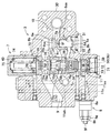
図2および図3は、上記油圧制御回路に組み込まれるホールディングコントロール弁3およびリリーフ弁8の具体的な構造を示す。図2に示すホールディングコントロール弁3は、上述のようにパイロットチェック弁6と、切換弁7と、リリーフ弁8とを主たる構成要素とし、これら構成要素は、その周辺の管路等を含んで1個のボデイ30に組み付けられている。ボデイ30に形成されたパイロットチェック弁用の第1孔31内に弁部材6aがスライド自在に収容されている。この弁部材6aの背面には背圧室6dが設けられるとともに、該背圧室6d内にスプリング6eを装着するためのスプリング受け部材6hがボデイ30における第1孔31の開口部に螺合されている。弁部材6aは、スプリング6eの弾力によって先側(上側)に押圧され、第1孔31の孔壁に形成された弁座6gに着座される。弁部材6aの先端面は第1受圧面6bとされ、受圧室6baを介してボデイ30に形成された負荷保持管路9に連通している。弁部材6aの側周面は第2受圧面6cとされ、受圧室6caを介して連結路10に連通している。そして、背圧室6dと第2受圧面6c側の受圧室6caとは絞り通路6fを介して連通している。これらによって、パイロットチェック弁6が構成されている。
2 and 3 show specific structures of the holding
ボデイ30には、前記第1孔31に平行に切換弁用の貫通孔32が形成されている。この貫通孔32には、スプール孔33を形成するとともに3個のポート36,37,38を備える2個のブッシュ34,35が、軸方向に沿って連なり気密的に嵌挿されている。貫通孔32の下端は、プラグ39が螺合されて封止され、また、上端はスプリング受け部材40が螺合されて封止されている。スプール孔33には1本のスプール70が摺動可能に嵌挿され、スプール70の下端とプラグ39との間の空間がパイロット室7aとされ、このパイロット室7aには、スプール70をストロークさせるためのピストン71が内蔵されている。このピストン71は、スプール70と同径のリリーフ作動ピストン72と、スプール70よりも大径のパイロットピストン73とよりなる分割ピストンによって構成されている。図例では、リリーフ作動ピストン72がパイロットピストン73に形成された筒部73aに収容されている(図1も参照)。
A through
ボデイ30には、パイロット圧5bの導入口50が形成され、該導入口50から導入されるパイロット圧5bは、パイロットピストン73とプラグ39との間に作用するよう構成されている。また、パイロットピストン73の外周部には、周溝73bが形成され、前記筒部73aの筒壁73aaには、周溝73bと筒部73aとを連通させるための横孔73cが形成されている(図1も参照)。この周溝73bには、リリーフ弁8のリリーフ油出口側分岐路11aから延びる経路11aaが連通し、該経路11aaから導入されるリリーフ油の圧力が、パイロットピストン73とリリーフ作動ピストン72との間に作用するよう構成されている。さらに、パイロット室7aにおけるスプール70の下端とピストン71の上端との間の空域は、オリフィス流路72bの上流側分岐経路11abに連結される連結経路7cに連通し、これらを介してドレーンタンク11c(図1および図4参照)に通じている。パイロット室7aおよびピストン71の構成および機能の詳細については後記する。
The
前記スプリング受け部材40内には、2本のスプリング74,75がスプール70との間に座金部材76を介して装着され、スプール70をピストン71側に弾発的に押圧している。スプール70は、中実円柱状部材からなり、図に示すように下端側から、パイロット室7aに臨むパイロット圧被作用部70aと、環状溝部70bと、該環状溝部70bに連なって形成され、可変絞り部7bを構成するノッチ部70cと、ブッシュ34の内壁と間で流通空間を構成する小径部70dと、前記ポート38を介しパイロットチェック弁6の受圧室6baに通じる負荷保持管路9を確保するための中継部70eと、スプリング74,75の弾力を受けるスプリング圧受部70fと、前記パイロット圧被作用部70aの上方部周面から前記小径部70dの上辺周面にかけて連繋するようスプール70の中実部内に形成された連繋流路70gとを備えている。中継部70eの存在によって実質的に分岐負荷保持管路9aが形成されることになる。
In the
図示のスプール70は切換弁7が遮断位置7Aにあることを示し、この状態では、パイロットチェック弁6の背圧室6dに通じるパイロット通路12と、受圧室6caに通じる延長路10aとは、ポート36、環状溝部70bおよびポート37を介して連通しているが、パイロット通路12および延長路10aと分岐負荷保持管路9aとは遮断されている。切換弁7が第1連通位置7Bに切換わる際には、スプール70が少許上昇し、これによってポート36がパイロット圧被作用部70aによって遮断されるとともにポート37が可変絞り部7bを構成するノッチ部70cを介してポート38に連通する。遮断位置7Aおよび第1連通位置7Bでは前記連繋流路70gの一端はブッシュ34によって封止されているのでその機能を奏していないが、スプール70がさらに上昇して切換弁7が第2連通位置7Cに切換わると、ポート36とポート38とが連繋流路70gを介して連通するとともにポート37が可変絞り部7bを構成するノッチ部70cを介してポート38に連通する。ポート36,37,38とスプール70の上記各部との位置関係は、このような切換弁7の切換態様に対応するよう形成されている。なお、スプリング受け部材40の内部は、スプール70のスクロール動作を許容し得るよう排出路7dを介してドレーンタンク11cに通じている。
The illustrated
次に図3も参照してリリーフ弁8について述べる。ボデイ30の側部には、リリーフ弁の取付用雌ねじ穴41が形成され、該雌ねじ穴41はボデイ30に形成された分岐路11に連通している。この雌ねじ穴41にバルブ本体8aが螺合固定されている。このバルブ本体8a内にはポペット8bが組み込まれ、ポペット8bはスプリング8cの弾力によって弁座8dに着座され、分岐路11からのリリーフ油の圧力がスプリング8cの弾力を上回るとポペット8bが弁座8dから離れるように構成されている。
Next, the
スプリング8cはバルブ本体8aの中空部に摺動自在に内設されたスプリング受け部材8eとポペット8bとの間に装着されている。スプリング受け部材8eの背面には雄ねじ部材からなる押当部材8fが配置され、この押当部材8fは、ロックナット8g、8hの螺合によってバルブ本体8aに対して位置決め固定されている。押当部材8fのロックナット8g、8hによる固定位置の調整によってスプリング8cのばね力の調整が可能とされている。バルブ本体8aには排出口8iが形成され、ポペット8bが弁座8dから離れると、リリーフ油は、この排出口8iを通じ、ボデイ30に形成されたリリーフ油出口側分岐路11aに流出する。
The
リリーフ油出口側分岐路11aは、さらに2経路11aa,11abに分岐され、一方の分岐経路11aaは切換弁7のパイロット室7aに導入され、他方の分岐経路11abはオリフィス流路72bを介してドレーンタンク11cに通じている(図4参照)。したがって、リリーフ弁8から流出したリリーフ油は、オリフィス流路72bの上流側で圧力損失が発生し、この圧力損失による圧力を有するリリーフ油が経路11aaより切換弁7のパイロット室7aに導入される。
The relief oil outlet
図1は、前記切換弁7におけるパイロット室7aとその周辺部分を概念的に示している。ボデイ30に形成された貫通孔32の下端はプラグ39によって封止され、プラグ39の上部のパイロット室7aには、上面が開口した有底筒形のパイロットピストン73が上下動可能に嵌着されている。パイロットピストン73の下面はパイロット圧を受圧する面とされ、該下面には、プラグ39の上面との間にパイロット油の溜空間となる凹部73dが形成されている。この凹部73dにパイロット圧5bが導入されるようになされている。パイロットピストン73の筒部73aの内径は、リリーフ作動ピストン72の外径と略同じないしは若干大きく形成され、この筒部73a内にスプール70と略同径のリリーフ作動ピストン72を上下動可能に収容している。パイロットピストン73の外周部には、周溝73bが形成され、筒部73aの筒壁73aaには周溝73bと筒部73aとを連通させるための横孔73cが形成されている。この周溝73bには、リリーフ弁8のリリーフ油出口側分岐路11aから延びる経路11aaが連通している。
FIG. 1 conceptually shows a pilot chamber 7a and its peripheral portion in the switching valve 7. The lower end of the through-
リリーフ作動ピストン72の下面はリリーフ油の油圧を受圧する面とされ、該下面には、パイロットピストン73の内底面との間にリリーフ油の溜空間となる凹部72aが形成されている。この凹部72aにリリーフ弁8から経路11aa、周溝73bおよび横孔73cを介してリリーフ油が導入されるようになされている。さらに、パイロットピストン73の凹部73dと筒部73aとの間にオリフィスを備えた流路(オリフィス流路)73eが形成され、リリーフ作動ピストン72の凹部72aと上面との間にもオリフィスを備えた流路(オリフィス流路)72bが形成され、これら2個のオリフィス流路73e,72bによって、パイロットピストン73のパイロット圧5bを受圧する面から、リリーフ作動ピストン72のスプール70に対面する側の面にかけての一連の連通路が構成されている。さらに、パイロット室7aにおけるスプール70の下端とリリーフ作動ピストン72の上面との間の空域は、上流側分岐経路11abに連結される連結経路7cに連通し、これらを介してドレーンタンク11cに通じている。
The lower surface of the
このような構成において、パイロットピストン73にパイロット圧5bが作用すると、パイロットピストン73がリリーフ作動ピストン72とともに押し上げられ、スプール70をストローク動作させる。パイロット圧5bが所定圧以下である場合は、スプール70のストローク量が小さく、切換弁7は第1連通位置7Bに切換わり、上述の各ポートの連通がなされる。また、パイロット圧5bが所定圧を超えると、スプール70のストローク量が大きくなり、切換弁7は第2連通位置7Cに切換わる。さらに、リリーフ弁8からのリリーフ油の油圧がリリーフ作動ピストン72に作用してパイロット圧5bとの合計圧力が所定圧を超えると、スプール70のストローク量が大きくなり、切換弁7は第2連通位置7Cに切換わる。このような動作は、ピストン71の径がスプール70の径より大であることによって、効果的になされる。
In such a configuration, when the
上記のようにピストン71を、パイロット圧5bを受圧するパイロットピストン73と、リリーフ作動時のリリーフ油の油圧を受圧するリリーフ作動ピストン72とに分割した結果、リリーフ弁8が作動すると、リリーフ弁8から流出するリリーフ油は、パイロットピストン73の横孔73cを通過し、凹部72aおよびオリフィス流路72bからリリーフ作動ピストン72の上面に達し、連結経路7cよりドレーンタンク11cに排出される。リリーフ弁8に前漏れが生じ、オリフィス流路72bの圧力損失によってリリーフ作動ピストン72に油圧力が作用した状態で、パイロットピストン73にパイロット圧5bによる油圧力が作用すると、リリーフ油による油圧力(両ピストン72,73間に作用する油圧力)は、パイロットピストン73に作用する油圧力と、スプール70を介して対抗するスプリング74,75の弾力とがつり合っている状態の内力となるので、パイロット圧5bに対抗する力とならない。したがって、リリーフ弁8に前漏れが発生する程度の高圧状態でも、パイロットチェック弁6の開口開始ポイントはパイロット圧5bに追従させることができ、シリンダ装置1の負荷状態によらず安定した操作性を得ることができる。そして、この実施形態のように、リリーフ作動ピストン72をパイロットピストン73の筒部73aに収容するようにすれば、軸方向にコンパクトな構造とすることができる。
As described above, when the
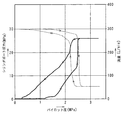
図5は、シリンダ装置のボトム側に38MPaが発生している状態を模擬した状態で、パイロット圧Pを負荷した場合のパイロット圧Pと、シリンダポート圧と、切換弁およびパイロットチェック弁を通過する流量との関係について実測した結果をグラフにしたものである。図5において実線は切換弁およびパイロットチェック弁を通過する流量の変化を、破線はシリンダポート圧の変化を示している。図5から理解されるとおり、流量増加側は、開口ポイントの設定値1MPaから流量が増加を始め、流量減少側は、1MPaで0L/minとなっている。このことはパイロット圧Pに対する追従性が良く、上記開口開始ポイントがずれていないことを意味している。
FIG. 5 shows a state where 38 MPa is generated on the bottom side of the cylinder device, and passes through the pilot pressure P, the cylinder port pressure, the switching valve, and the pilot check valve when the pilot pressure P is applied. The graph shows the results of actual measurement of the relationship with the flow rate. In FIG. 5, a solid line indicates a change in the flow rate passing through the switching valve and the pilot check valve, and a broken line indicates a change in the cylinder port pressure. As understood from FIG. 5, on the flow rate increasing side, the flow rate starts to increase from the
図6は、本発明の他の実施形態のホールディングコントロール弁の一部の断面図である。本実施の形態は、図1に示す前述の実施形態とはピストン71の構造が異なる。すなわち、パイロットピストン73と、リリーフ作動ピストン72とは同径でかつともにスプール70の径より大とされ、両者が貫通孔32の軸方向(スプール70の軸方向)に連なるように配置されている。パイロットピストン73の下面には、上記と同様、プラグ39の上面との間にパイロット油の溜空間となる凹部73dが形成され、この凹部73dにパイロット圧5bが導入されるようになされている。リリーフ作動ピストン72は、パイロットピストン73の上に置かれ、両ピストン72,73間に、リリーフ弁8からのリリーフ油が経路11aaを経て導入されるようになされている。また、両ピストン72,73には、オリフィス流路72b,73eが形成され、これらオリフィス流路72b,73eによって、パイロットピストン73のパイロット圧5bを受圧する面から、リリーフ作動ピストン72のスプール70に対面する側の面にかけての一連の連通路が構成されている。
FIG. 6 is a cross-sectional view of a part of a holding control valve according to another embodiment of the present invention. This embodiment differs from the above-described embodiment shown in FIG. 1 in the structure of the
この実施形態の場合も、ピストン71がリリーフ作動ピストン72およびパイロットピストン73によって構成されるから、リリーフ弁8に前漏れが発生する程度の高圧状態でも、パイロットチェック弁6の開口開始ポイントはパイロット圧5bに追従させることができ、シリンダ装置1の負荷状態によらず安定した操作性を得ることができる。また、リリーフ作動ピストン72およびパイロットピストン73の構造がともにシンプルであり、加工コストが嵩む懸念がない。その他の構成は上記の実施形態と同様であるから、共通部分に同一の符号を付し、その説明を省略する。
Also in this embodiment, since the
なお、上記の実施形態では、被作動体が油圧ショベル等のような油圧作業機器におけるシリンダ装置である場合について述べたが、その他の油圧作業機器に組み込まれる被作動体であっても良い。また、図2に示すホールディングコントロール弁の構造は図示のものに限定されず、図4に示す制御回路図の構成が反映されるものであれば、他の構造のものであっても良い。 In the above embodiment, the case where the actuated body is a cylinder device in a hydraulic work device such as a hydraulic excavator has been described. However, the actuated body may be incorporated in another hydraulic work device. Further, the structure of the holding control valve shown in FIG. 2 is not limited to that shown in the figure, and may be of another structure as long as the configuration of the control circuit diagram shown in FIG. 4 is reflected.
1 シリンダ装置
1a ボトム側圧力室
1b ロッド側圧力室
3 ホールディングコントロール弁
6 パイロットチェック弁
5a,5b パイロット圧
6d 背圧室
7 切換弁
7a パイロット室
8 リリーフ弁
10 連結路
11 分岐路
70 スプール
71 ピストン
72 リリーフ作動ピストン
72b,73e オリフィス流路
73 パイロットピストン
73a 筒部
73aa 筒壁
74,75 スプリング
DESCRIPTION OF
Claims (5)
前記被作動体の圧力室に連結されるパイロットチェック弁と、
前記パイロットチェック弁の背圧室の圧力が前記被作動体の圧力室の負荷圧となっているとき、パイロットチェック弁によって被作動体の圧力室側からの作動油の流れを阻止し、パイロットチェック弁の背圧室の作動油を排出したとき、このパイロットチェック弁が開いて被作動体の圧力室側からの作動油の流れを許容するために、パイロット圧の導入によってスプールをスプリング圧に抗して動作させるよう構成された切換弁と、
前記被作動体の圧力室とパイロットチェック弁との連結路から分岐する分岐路に配設され、リリーフ油の出口側が前記切換弁のパイロット圧の導入部側に連結されるリリーフ弁とを含み、
前記スプールは、パイロット圧の導入に伴い動作するスプール径よりも大径のピストンによってストロークするように構成され、
前記ピストンは、パイロット圧を受圧するパイロットピストンと、リリーフ弁が作動したときに排出されるリリーフ油の圧力を受圧するようスプールに近接して配置されたリリーフ作動ピストンとに分割され、前記リリーフ油はパイロットピストンとリリーフ作動ピストンとの間に導入されることを特徴とするホールディングコントロール弁。 A holding control valve used in a hydraulic control circuit for operating an actuated body,
A pilot check valve coupled to the pressure chamber of the actuated body;
When the pressure of the back pressure chamber of the pilot check valve is the load pressure of the pressure chamber of the actuated body, the pilot check valve prevents the flow of hydraulic oil from the pressure chamber side of the actuated body, and the pilot check When the hydraulic oil in the back pressure chamber of the valve is discharged, the pilot check valve opens to allow the hydraulic oil to flow from the pressure chamber side of the operated body. A switching valve configured to operate
A relief valve disposed on a branch path branched from a connection path between the pressure chamber of the actuated body and a pilot check valve, and having a relief oil outlet side connected to a pilot pressure introduction side of the switching valve;
The spool is configured to be stroked by a piston having a diameter larger than a spool diameter that operates in accordance with introduction of pilot pressure,
The piston is divided into a pilot piston that receives a pilot pressure, and a relief operating piston that is disposed in the vicinity of the spool so as to receive the pressure of the relief oil that is discharged when the relief valve is operated. Is a holding control valve that is introduced between the pilot piston and the relief operating piston.
Priority Applications (3)
| Application Number | Priority Date | Filing Date | Title |
|---|---|---|---|
| JP2008094358A JP4473322B2 (en) | 2008-03-31 | 2008-03-31 | Holding control valve |
| EP20090003972 EP2107253B1 (en) | 2008-03-31 | 2009-03-19 | Holding control valve |
| US12/410,259 US8356546B2 (en) | 2008-03-31 | 2009-03-24 | Holding control valve |
Applications Claiming Priority (1)
| Application Number | Priority Date | Filing Date | Title |
|---|---|---|---|
| JP2008094358A JP4473322B2 (en) | 2008-03-31 | 2008-03-31 | Holding control valve |
Publications (2)
| Publication Number | Publication Date |
|---|---|
| JP2009243669A JP2009243669A (en) | 2009-10-22 |
| JP4473322B2 true JP4473322B2 (en) | 2010-06-02 |
Family
ID=40875051
Family Applications (1)
| Application Number | Title | Priority Date | Filing Date |
|---|---|---|---|
| JP2008094358A Active JP4473322B2 (en) | 2008-03-31 | 2008-03-31 | Holding control valve |
Country Status (3)
| Country | Link |
|---|---|
| US (1) | US8356546B2 (en) |
| EP (1) | EP2107253B1 (en) |
| JP (1) | JP4473322B2 (en) |
Families Citing this family (8)
| Publication number | Priority date | Publication date | Assignee | Title |
|---|---|---|---|---|
| WO2012091194A1 (en) * | 2010-12-28 | 2012-07-05 | 볼보 컨스트럭션 이큅먼트 에이비 | Holding valve for construction equipment |
| JP5822233B2 (en) * | 2012-03-27 | 2015-11-24 | Kyb株式会社 | Fluid pressure control device |
| JP2014173616A (en) * | 2013-03-06 | 2014-09-22 | Caterpillar Sarl | Pressure loss reducing circuit for work machine |
| GB2514112C (en) * | 2013-05-13 | 2016-11-30 | Caterpillar Inc | Valve Arrangement |
| JP6397715B2 (en) * | 2014-10-06 | 2018-09-26 | Kyb−Ys株式会社 | Fluid pressure control device |
| WO2016116840A1 (en) * | 2015-01-19 | 2016-07-28 | Interpump Hydraulics S.P.A. | A directional control valve group installable on a truck for commanding a double-acting hydraulic user, and a hydraulic plant comprising the directional control valve group. |
| JP6502813B2 (en) * | 2015-09-25 | 2019-04-17 | Kyb株式会社 | Fluid pressure control device |
| JP7116584B2 (en) | 2018-05-07 | 2022-08-10 | 川崎重工業株式会社 | valve device |
Family Cites Families (4)
| Publication number | Priority date | Publication date | Assignee | Title |
|---|---|---|---|---|
| FR2479358A1 (en) * | 1980-03-25 | 1981-10-02 | Richier Sa Nle Indle | Mechanical digger lifting jack with safety device - monitors pressure after flexible pipeline section to control automatic non-return valve which can be selectively inhibited |
| DE19701114A1 (en) | 1997-01-15 | 1998-07-16 | Rexroth Mannesmann Gmbh | Hydraulic pilot-controlled check valve |
| JP3919399B2 (en) | 1998-11-25 | 2007-05-23 | カヤバ工業株式会社 | Hydraulic control circuit |
| EP1143151B1 (en) * | 1999-10-20 | 2007-01-03 | Hitachi Construction Machinery Co., Ltd. | Pipe breakage control valve device |
-
2008
- 2008-03-31 JP JP2008094358A patent/JP4473322B2/en active Active
-
2009
- 2009-03-19 EP EP20090003972 patent/EP2107253B1/en active Active
- 2009-03-24 US US12/410,259 patent/US8356546B2/en active Active
Also Published As
| Publication number | Publication date |
|---|---|
| EP2107253A3 (en) | 2010-03-24 |
| US20090241765A1 (en) | 2009-10-01 |
| JP2009243669A (en) | 2009-10-22 |
| EP2107253B1 (en) | 2012-06-27 |
| US8356546B2 (en) | 2013-01-22 |
| EP2107253A2 (en) | 2009-10-07 |
Similar Documents
| Publication | Publication Date | Title |
|---|---|---|
| JP4473322B2 (en) | Holding control valve | |
| KR100764119B1 (en) | Pilot poppet type relief valve | |
| KR20150110517A (en) | Fluid pressure control device | |
| JP2006038213A (en) | Variable regeneration valve for heavy equipment | |
| US20110132476A1 (en) | Hydraulic valve device | |
| CN113544390A (en) | Flow control valve | |
| JP6822930B2 (en) | Flow control valve | |
| KR100240092B1 (en) | A locking device of operating apparatus for construction heavy equipment | |
| KR20050081058A (en) | Relief valve | |
| US7913612B2 (en) | Actuator control device | |
| KR20180085784A (en) | Pilot type switching valve | |
| JP6909164B2 (en) | Fluid pressure controller | |
| JP4918001B2 (en) | Fluid pressure control device | |
| WO1996000351A1 (en) | Directional control valve device provided with a pressure compensating valve | |
| GB2383381A (en) | Actuator retraction controller | |
| US11293560B2 (en) | Solenoid flow control valve | |
| JPH0875020A (en) | Pressure control valve | |
| JP2018021605A (en) | Fluid pressure control device | |
| JP2017062010A (en) | Fluid pressure control device | |
| JP4791823B2 (en) | Hydraulic control valve used in load sensing type hydraulic control device | |
| KR102088562B1 (en) | Pilot poppet type relief valve | |
| KR20050081056A (en) | Pilot poppet type relief valve | |
| WO2023176686A1 (en) | Fluid pressure control device | |
| US20240271640A1 (en) | Fluid pressure control device | |
| WO2023176685A1 (en) | Fluid pressure control device |
Legal Events
| Date | Code | Title | Description |
|---|---|---|---|
| A131 | Notification of reasons for refusal |
Free format text: JAPANESE INTERMEDIATE CODE: A131 Effective date: 20091110 |
|
| A521 | Request for written amendment filed |
Free format text: JAPANESE INTERMEDIATE CODE: A523 Effective date: 20100112 |
|
| TRDD | Decision of grant or rejection written | ||
| A01 | Written decision to grant a patent or to grant a registration (utility model) |
Free format text: JAPANESE INTERMEDIATE CODE: A01 Effective date: 20100302 |
|
| A01 | Written decision to grant a patent or to grant a registration (utility model) |
Free format text: JAPANESE INTERMEDIATE CODE: A01 |
|
| A61 | First payment of annual fees (during grant procedure) |
Free format text: JAPANESE INTERMEDIATE CODE: A61 Effective date: 20100304 |
|
| FPAY | Renewal fee payment (event date is renewal date of database) |
Free format text: PAYMENT UNTIL: 20130312 Year of fee payment: 3 |
|
| R150 | Certificate of patent or registration of utility model |
Ref document number: 4473322 Country of ref document: JP Free format text: JAPANESE INTERMEDIATE CODE: R150 Free format text: JAPANESE INTERMEDIATE CODE: R150 |
|
| S111 | Request for change of ownership or part of ownership |
Free format text: JAPANESE INTERMEDIATE CODE: R313111 |
|
| FPAY | Renewal fee payment (event date is renewal date of database) |
Free format text: PAYMENT UNTIL: 20130312 Year of fee payment: 3 |
|
| R350 | Written notification of registration of transfer |
Free format text: JAPANESE INTERMEDIATE CODE: R350 |
|
| FPAY | Renewal fee payment (event date is renewal date of database) |
Free format text: PAYMENT UNTIL: 20130312 Year of fee payment: 3 |
|
| FPAY | Renewal fee payment (event date is renewal date of database) |
Free format text: PAYMENT UNTIL: 20140312 Year of fee payment: 4 |
|
| FPAY | Renewal fee payment (event date is renewal date of database) |
Free format text: PAYMENT UNTIL: 20150312 Year of fee payment: 5 |
|
| R250 | Receipt of annual fees |
Free format text: JAPANESE INTERMEDIATE CODE: R250 |